
Dynamic Tensile Properties of CFRP Manufactured by PCM and WCM: Effect of Strain Rate and Configurations

Department of Transportation Engineering, Nanjing Vocational University of Industry Technology, Nanjing 210023, China
Crystals 2021, 11(12), 1491; https://0-doi-org.brum.beds.ac.uk/10.3390/cryst11121491
Submission received: 23 October 2021
/
Revised: 15 November 2021
/
Accepted: 29 November 2021
/
Published: 1 December 2021
(This article belongs to the Special Issue Feature Papers on "Hybrid and Composite Crystalline Materials" 2021-2022)
Abstract
:Carbon fiber-reinforced plastic (CFRP) is a promising material to achieve lightweight automotive components. The effects of the strain rate and configurations of CFRP on dynamic tensile properties have not yet been fully explored; thus, its lightweight benefits cannot be maximized. In this paper, the dynamic tensile properties of CFRPs, tested using two different processes with two different resins and four different configurations, were studied with a strain rate from 0.001 to 500 s−1. The tensile strength, modulus, failure strain, and fracture mechanism were analyzed. It was found that the dynamic performance enhances the strength and modulus, whereas it decreases the failure strain. The two processes demonstrated the same level of tensile strength but via different fracture mechanisms. Fiber orientation also significantly affects the fracture mode of CFRP. Resins and configurations both have an influence on strain rate sensitivity. An analytic model was proposed to examine the strain rate sensitivity of CFRPs with different processes and configurations. The proposed model agreed well with the experimental data, and it can be used in simulations to maximize the lightweight properties of CFRP.
1. Introduction
Lightweight materials are important to achieve vehicle energy conservation and a reduction in carbon dioxide emissions. This makes it possible to improve vehicle acceleration, braking, handling, and many other parameters. Carbon fiber-reinforced plastic (CFRP) is an outstanding lightweight material due to its high specific strength, high specific modulus, good fatigue strength, corrosion resistance, and creep resistance [1]. Mass production applications (e.g., B-pillar by BMW) and studies on vehicle parts such as battery boxes [2] and fenders [3] have demonstrated the lightweight properties of CFRP.
Many studies have been conducted on the dynamic tensile properties of CFRP. Jacob et al. [4] reviewed whether strain rate affects the mechanical properties of a polymer composite; although conflicting opinions were found, most studies stated that the tensile properties of polymer composite have strain rate sensitivity. Ma et al. [5] studied the strain rate-dependent deformation of multilayer CFRP using an in situ tensile test, and they found a “low–high–low” variation tendency of the modulus and tensile strength as a function of strain rate from 2.6 × 10⁻⁶ to 2.6 × 10⁻³ s−1. Zhang et al. [6] found that the tensile strength, modulus and failure strain of CFRP are related to strain rate in the range 7 × 10⁻⁵ to 240 s−1. However, in terms of the strain rate sensitivity of tensile strength, modulus, and failure strain, studies have presented different results. Okoli [7] and Duan et al. [8] found that the tensile strength, modulus, and failure strain of glass fiber-reinforced plastics increase with increasing strain rate. Kimura et al. [9] found that strain rate sensitivity of the tensile strength and modulus is higher than that of failure strain. Naresh et al. [10] studied the tensile strength of (0/90)s CFRP in the range of strain rate from 0.0016 to 542 s−1, and they found that the failure strain decreases with the increase in strain rate, whereas the tensile strength and modulus remain approximately constant. In automotive industrial applications, CFRP is normally manufactured into components layer by layer in a configuration with different orientations, in order to improve the mechanical properties in different directions. Configurations have a significant effect on the strain rate sensitivity of the tensile properties of CFRP. Gilat et al. [11] compared the tensile properties of CFRP in different configurations in a strain rate range of 10−5 to 600 s−1; a higher modulus was observed for all configurations with increasing strain rate, whereas the tensile strength of (90)s and [10]s barely increased. Wang et al. [12] studied the dynamic properties of CFRP in the range of 10−5 to 104 s−1 for (45/−45)s and (0/45/90/−45)s configurations, and they found that the (45/−45)s configuration has a stronger strain rate sensitivity. Kwon et al. [13] and Taniguchi et al. [14] evaluated the effect of stain rate on the tensile properties of CFRP, and they found that the influence of strain rate is barely observed in the (0) direction, whereas that in the (90) direction is remarkable. Therefore, the effect of stain rate on tensile properties, including strength, modulus, and failure strain, has not been completely established, in addition to the effect of CFRP configuration; quantitative studies are lacking.
Meanwhile, the fracture modes of CFRP are a complex phenomenon that depends highly on processes and configurations. Oya et al. [15] studied the tensile fracture of (0)s CFRP and concluded that the fracture modes can be categorized as brush or straight fracture modes. Azadi et al. [16] studied the tensile failure mechanism in an open-hole (02/903/02)s CFRP, and three modes (matrix cracking, fiber breakage, and debonding of fibers from the matrix) were found. Among them, debonding was the dominant failure mechanism. Maekawa et al. [17] compared the fracture behavior of (0/45/−45/90)s between T300 and T800 CFRP composites; intralaminar delamination was found in different layers (90) in the T300 composite and (90/−45) and (45/−45) interlaminate in the T800 composite. Naresh et al. [18] investigated the fracture modes of CFRP, and they found a failure mechanism switch from matrix microcracking and fiber–matrix interface microcracking to fiber pullout, matrix damage, as well as fiber–matrix interface cracking from a quasi-static to a high strain rate. However, thorough studies of the fracture mechanism of CFRP are lacking, and the effect of configurations on the fracture mode is not clear.
Accordingly, automotive companies have struggled to accurately simulate CFRP parts and, thus, cannot maximize the lightweight effects of CFRP. This study focused on the dynamic tensile properties to reveal the effect of strain rate and fracture mechanism. The CFRP composites in this study were provided by two automotive commercial CFRP suppliers, and the selected manufacturing processes were prepreg molding (PCM) and resin film melting molding (WCM), since molding is the most suitable preparation method for lightweight automotive parts [19]. In this study, CFRP composites in four configurations, namely, (0)s, (90)s, (0/45/−45/90)s, and (90/−45/45/0)s, were tested at different strain rates from 0.001 to 500 s−1; (0/45/−45/90)s and (90/−45/45/0)s are two typical configurations used in automotive components, such as BMW and Volvo Polestar. The effects of strain rate and configurations on the tensile properties are discussed, as well as the fracture mechanism of different configurations. An analytical model is proposed to predict the effect of strain rate and different configurations on CFRP tensile properties.
2. Materials and Methods
The CFRP materials in this paper were prepared using commercial PCM and WCM processes HRC (Suzhou, China) and KOLLER (Nanjing, China), respectively. The PCM CFRP was made using Toray T700 carbon fiber and Hengshen EM817 resin. The WCM CFRP was made using SIGRI SGL400k large silk carbon fiber and Henkel H5 resin. The carbon volume fraction of both processes was 60%.
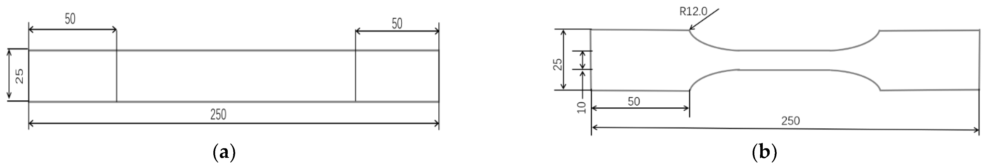
The tensile test was carried out under quasi-static and dynamic conditions according to the ASTM D 3039 standard, and all the specimens were 2 mm thick. The tensile specimens used in the quasi-static test were plate samples with a length of 250 mm and width of 25 mm. The two ends of the specimen constituted 50 mm stiffeners, with a width of 25 mm and thickness of 2 mm, as shown in Figure 1a. The tests used in the dynamic test were dumbbell-shaped, with a total length of 250 mm and thickness of 2 mm, as shown in Figure 1b. The tensile specimens were wire-cut from a 300 mm × 400 mm × 2 mm plate, and the plates were prepared by HRC and KOLLER commercial suppliers in one batch.
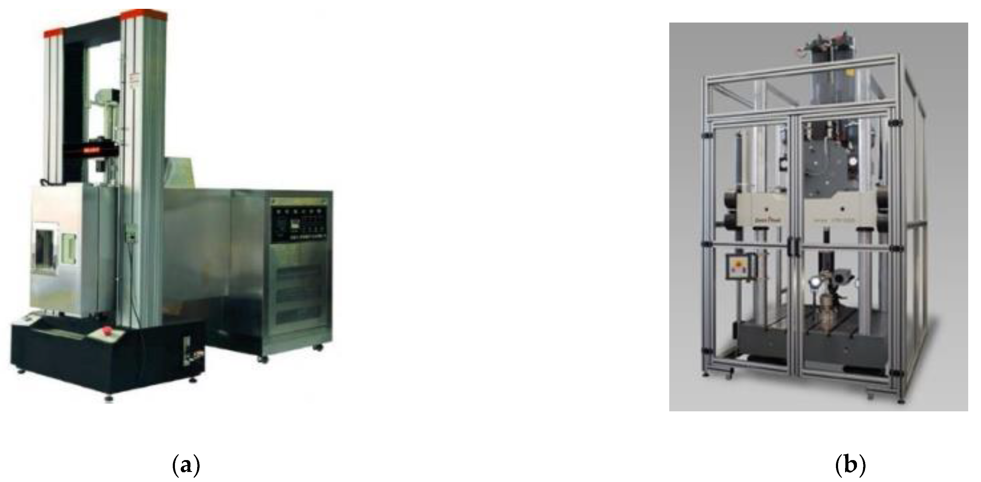
An electronic universal testing machine (Figure 2a) was used for the quasi-static test, and the equipment model was CMT5205 (MTS, Tianjing, China) The measuring range of the equipment is up to 200 kN, and the test speed range is 0.1–500 mm/min. A large dynamic testing machine (Figure 2b) was used for the dynamic tensile test, and the equipment model was HTM16020 (Zwick, Tianjing, China), with a measuring range up to 100 kN and a test speed range of 0.001–20 m/s. During the dynamic and static experiments, the FASTCAM SA-Z high-speed camera (Photron, Yianjin, China) was used for image and video recording. The static strain rate was 0.001 s−1, and the four dynamic strain rates were 1 s−1, 10 s−1, 100 s−1, and 500 s−1. The strain rate was calculated as a function of the test speed divided by gauge length; thus, to achieve a test strain rate of 500 s−1, the gauge length was chosen to be 40 mm. The specific test matrix is shown in Table 1; for each condition, three specimens were tested.
3. Results
3.1. (0)s Configuration
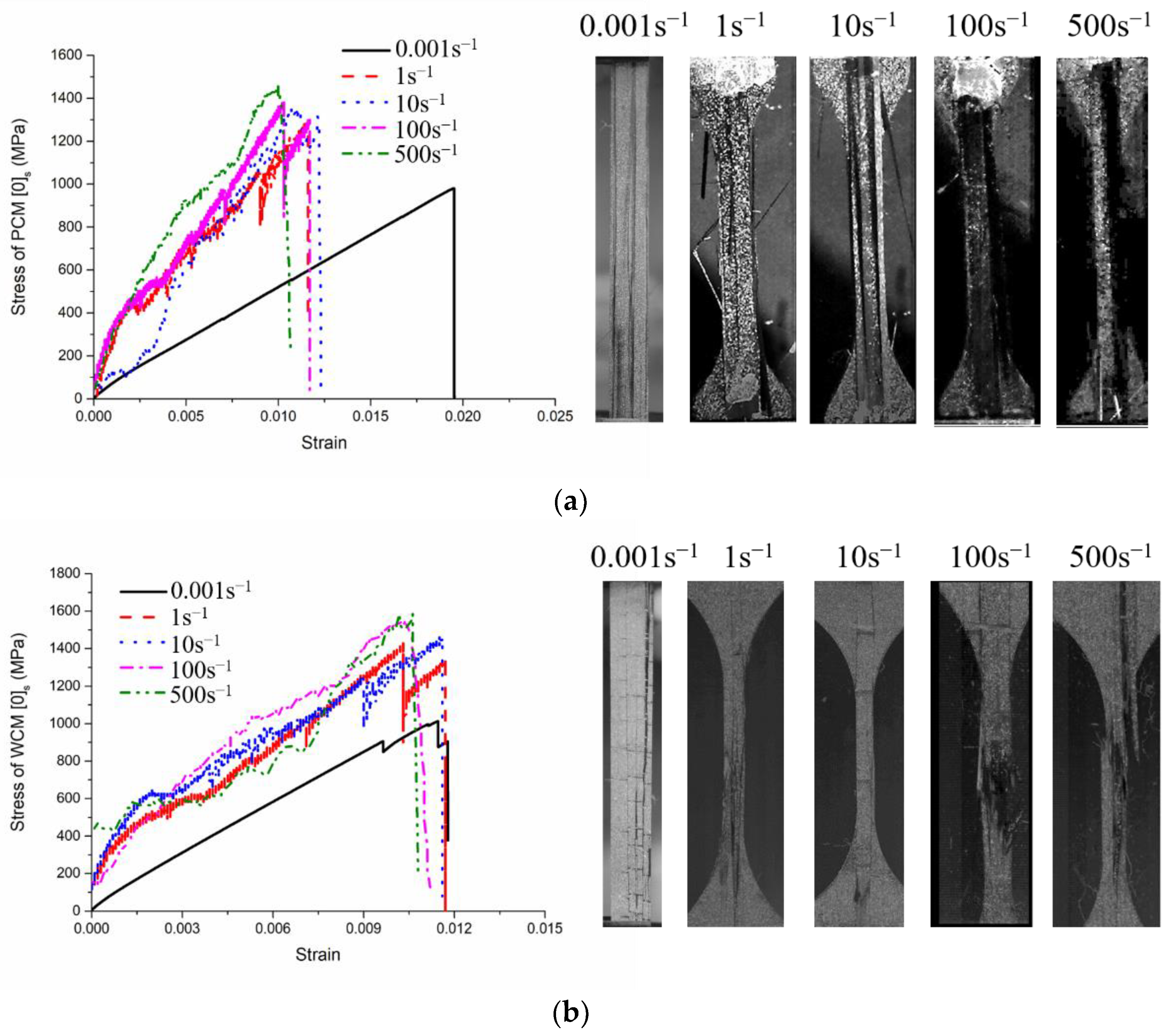
Figure 3a,b illustrate the tensile stress–strain curves and fracture photos of the (0)s configuration made using PCM and WCM processes, respectively. As seen from Figure 3a,b, the dynamic tensile strength and modulus of the (0)s configuration made using two different processes showed different rates of increment as the strain rate changed from 0.001 to 500 s−1. In terms of the tensile strength and modulus, the failure strain of the (0)s configuration showed the opposite trend. The failure strain in the dynamic condition was lower than that in the static condition, illustrating a decreasing trend as the strain rate changed from 0.001 to 500 s−1. The fracture mode of the (0)s configuration made using both processes was a brush fracture mode with many splitting cracks along the fiber direction [15]; as the strain rate increased, the brush area increased. However, comparing Figure 3a,b, it can be observed that the brush fracture of PCM was different from that of WCM, and this was more observable at a high strain rate. The detailed mechanism is discussed in Section 4.1.
3.2. (90)s Configuration
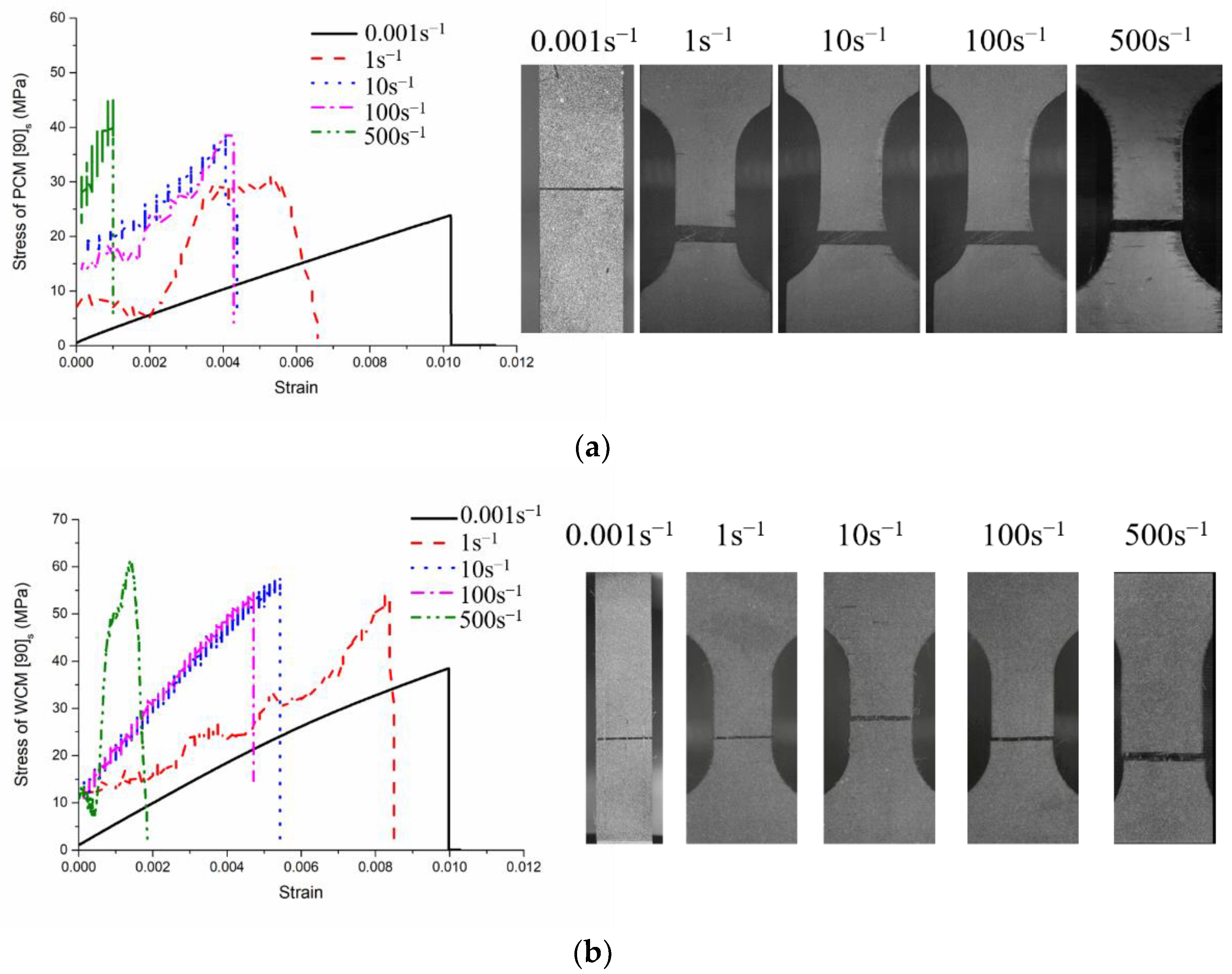
Figure 4a,b illustrate the tensile stress–strain curves and fracture photos of the (90)s configuration made using the PCM and WCM processes, respectively. As seen from Figure 4a,b, the dynamic tensile strength and modulus of the (90)s configuration made using both processes were higher than in the static condition, and they showed a general increasing trend as the strain rate changed from 0.001 to 500 s−1. In terms of the failure strain, the (90)s configuration of both processes illustrated a decreasing trend as the strain rate changed from 0.001 to 500 s−1. The fracture mode of the (90)s configuration made using both processes was a straight fracture mode with a flat fracture surface, in which cracks propagated transversely to the fiber direction [15]; however, as the strain rate increased, the straight fracture did not show much difference.
3.3. Typical Configurations
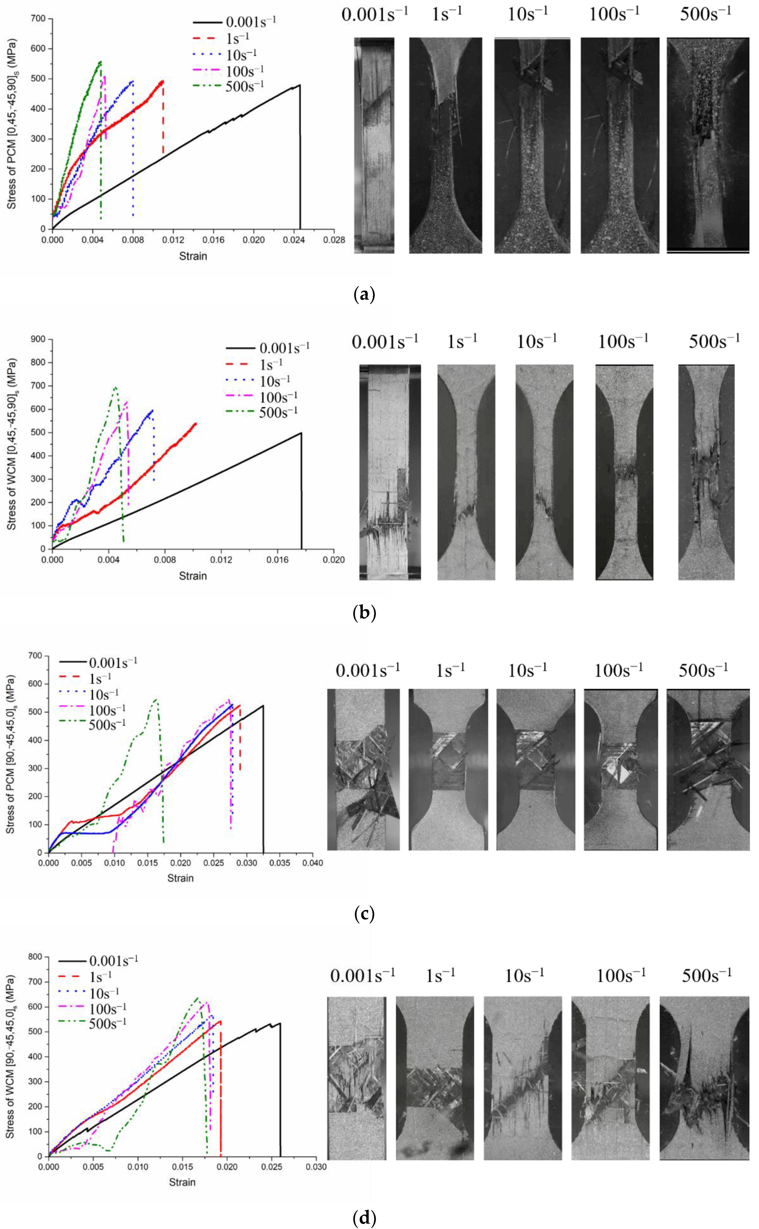
Figure 5 shows the tensile stress–strain curves and fracture photos of the two typical configurations made using both processes. Figure 5a–d present the results for the (0/45/−45/90)s configuration made using PCM, the (0/45/−45/90)s configuration made using WCM, the (90/−45/45/0)s configuration made using PCM, and the (90/−45/45/0)s configuration made using WCM, respectively. As seen from Figure 5a–d, the dynamic tensile strength and modulus were higher than in static conditions in all cases; in general, they illustrated an increasing trend as the strain rate increased. The failure strain in the dynamic condition of both typical configurations made using both processes was lower than that in the static condition; in general, a reduction in the strain rate was observed.
In terms of the fracture mode, the (0/45/−45/90)s configuration made using both processes showed a mixture of brush and shear fracture, where splitting occurred at the interface between the fiber and matrix along the diagonal direction of loading [13]. On the other hand, the (90/−45/45/0)s configuration made using both processes showed a mixture of straight and shear fracture. It should be noted that the fracture area increased with the increase in strain rate. Through a comparison of Figure 5a,c and Figure 5b,d, it can be seen that the fracture mode was similar between PCM and WCM, but the fracture morphology was slightly different, related to the fracture mechanism, as discussed in Section 4.1.
4. Discussion
4.1. Fracture Mechanism of Different Configurations
From the above findings, it can be observed that the fracture modes of the (0)s and (90)s configurations were brush and straight fracture, respectively. The fracture mode of the typical configurations was a mixture of top-layer and shear fracture. Although the fracture modes of PCM and WCM were similar, the fracture morphologies between the two processes were different, and the difference is more obvious at a higher strain rate. This is because the fracture mechanisms of PCM and WCM are different.
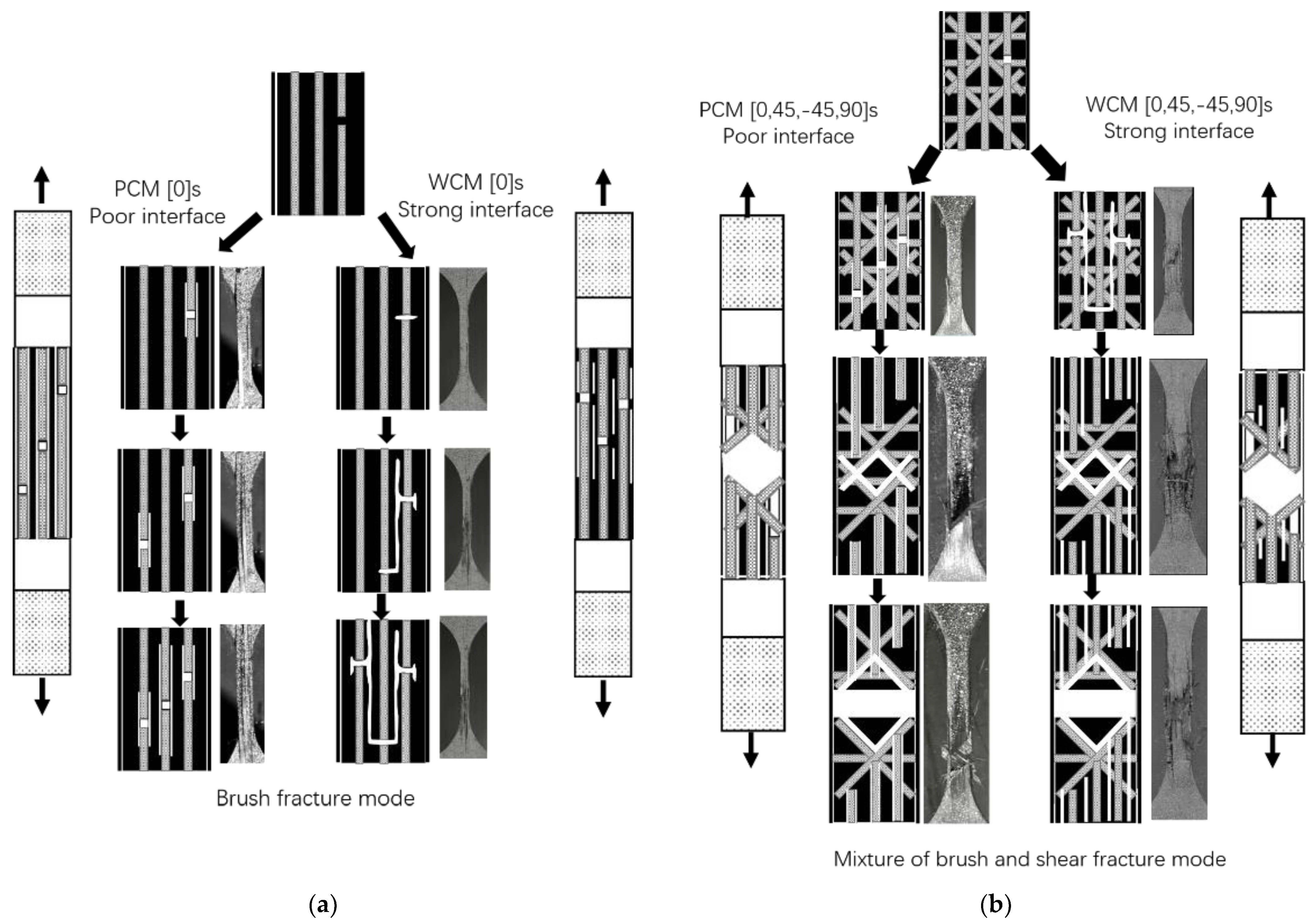
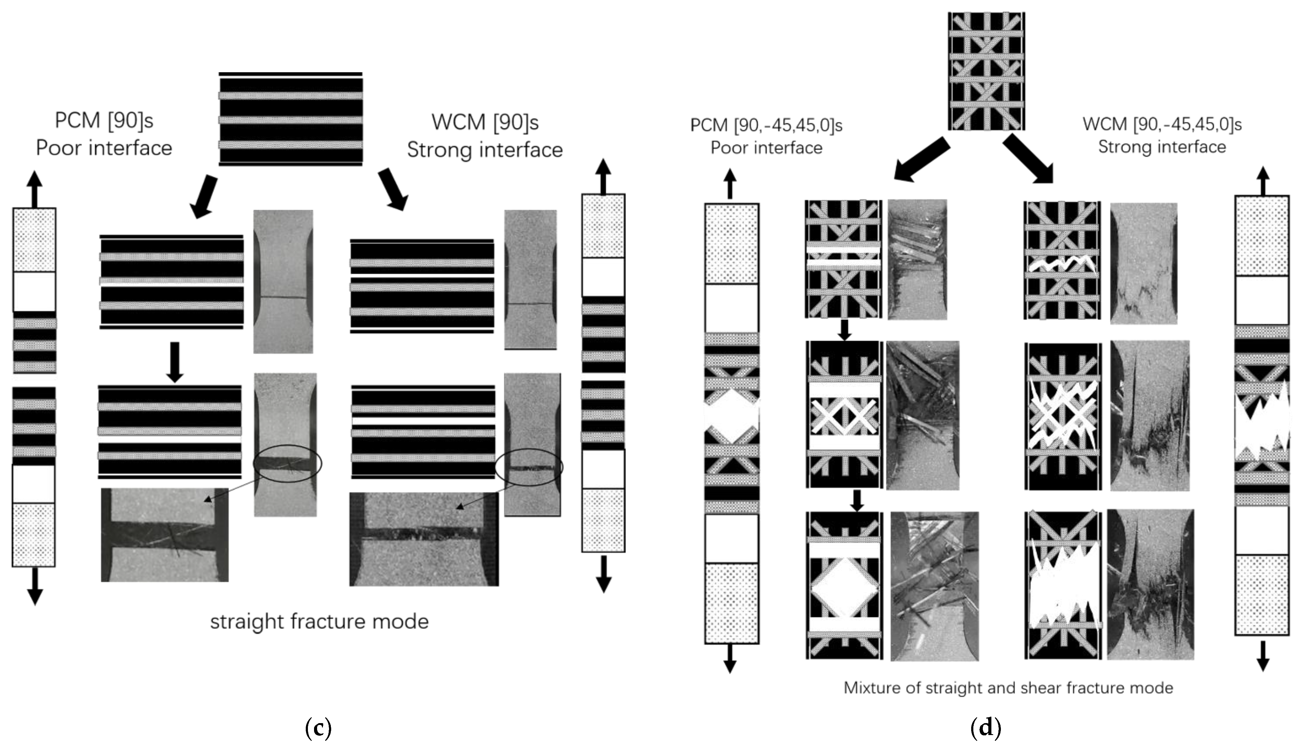
Fracture is a process of microcrack generation and propagation; the first microcrack is always generated at the debonding point. Similar opinions have been introduced in other reinforced composites [17,18,20]. In CFRP composites, the first debonding point typically depends on the lower value of the interfacial adhesion between fiber and resin, as well as the lowest bearing point of resin matrix [16,21]. Figure 6a–d illustrate the fracture mechanism and fracture process photos of the (0)s, [0/45/−45/90]s, (90)s, and (90/−45/45/0)s configurations made using both processes. From Figure 6, it can be observed that, although the macro-fracture modes of the two processes were similar for each configuration, the micro-fracture mechanisms were different. From Figure 6d, it can be seen that the first microcrack of the PCM process appeared at the fiber–matrix interface, while that of the WCM process appeared in the resin matrix. This means that the fiber–matrix interface is the first debonding point in PCM, while the resin matrix is the first debonding point in WCM.
For the (0)s configuration (Figure 6a), it can be observed that the first fracture appeared in the local fiber near the boundary separation. For the PCM process, since the strength of the fiber–matrix interface was lower than the strength of the resin matrix, cracks propagated along the interface, resulting in brush fracture. Since the strength of the WCM interface was stronger than that of the resin matrix, cracks propagated in the matrix vertically and horizontally, resulting in brush fracture. For the (0/45/−45/90)s configuration (Figure 6b), since the top layer was (0), the first fracture occurred in the surface boundary fiber and then diffused along the interface for PCM and in the resin matrix for WCM, similar to the (0)s configuration. Subsequently, cracks propagated under the stress of (±45) layers, resulting in shear fracture. For the (90)s configuration (Figure 6c), the fracture mode of PCM and WCM was a straight fracture with a flat fracture surface. Similar to the (0)s configuration, the first crack in PCM occurred at the fiber–matrix interface, whereas the first crack in WCM occurred in the resin matrix. This can be easily distinguished in Figure 6c, showing fibers in the fractured area in the PCM sample but not in the WCM sample. This is the evidence that the cracks in PCM propagated along the fiber–matrix interface and, thus, left individual fibers in the fractured area. For the (90/−45/45/0)s configuration, since the top layer was (90), the first crack in PCM occurred at the fiber–matrix interface, while whereas in WCM occurred in the resin matrix, as clearly observed in Figure 6d. Then, cracks propagated under the stress of (±45) layers, resulting in shear fracture. Therefore, the fracture mode of the CFRP configuration was partly determined by the fracture of the top layer.
Therefore, the fracture mode of the (0) layer was brush fracture, the fracture mode of the (90) layer was straight fracture, the fracture mode of the (±45) layers was shear fracture. The fracture mode of the CFRP was dependent on its configuration; when the middle layer was the same as the top layer, the fracture mode of the CFRP was the same as the fracture mode of the top layer, whereas, when the middle layer was (±45), the fracture mode of the CFRP was a mixture of top-layer and shear fracture.
The manufacturing process also affects the fracture mode by affecting the weakest point of CFRP materials. In this study, since PCM and WCM are two different processes, the resin was not identical, resulting in different interfacial strengths between the fiber and resin. In addition, the strain rate had an effect on the fracture, whereby the fracture area increased with the strain rate. A similar phenomenon was found for glass-fiber-reinforced resin materials by Azadi et.al (16). With the increase in strain rate, the internal stress of CFRP is high, leading to the production of unconnected microcracks. When the loading strain reaches the limit, these microcracks expand rapidly, resulting in a more violent and larger-area failure.
4.2. Strain Rate Sensitivity of Different Configurations
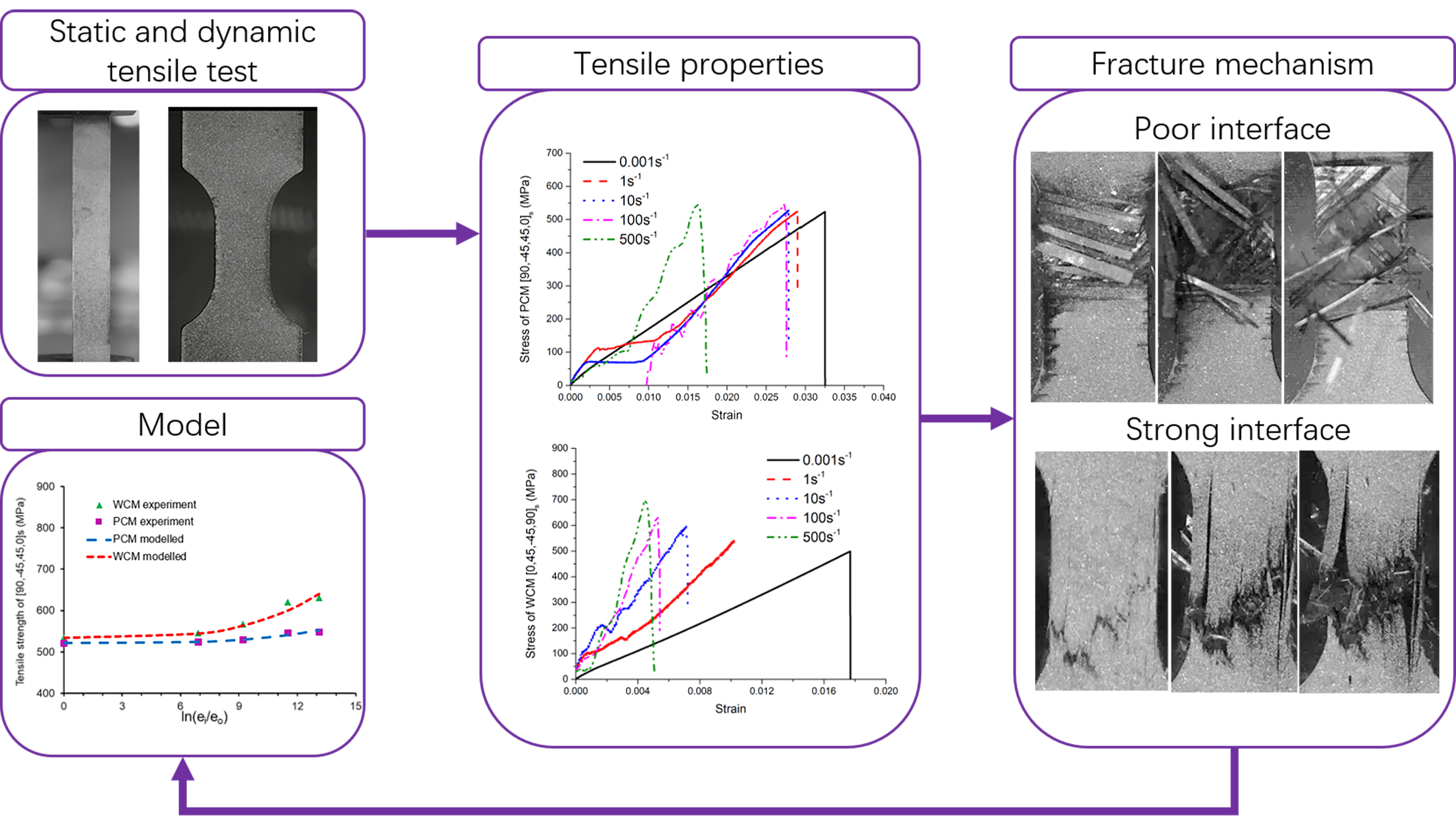
As described in Section 3, it was found that, as the strain rate increased, the tensile strength and modulus demonstrated a strain rate enhancement, whereas the failure strain showed a strain rate reduction. Moreover, the tensile properties of CFRP manufactured using both processes had different strain rate sensitivities. Since the examined CFRP exhibited brittle fracture (Figure 3, Figure 4 and Figure 5), the tensile strength had a highly opposite relationship with the failure strain. The tensile strength and modulus are discussed below.
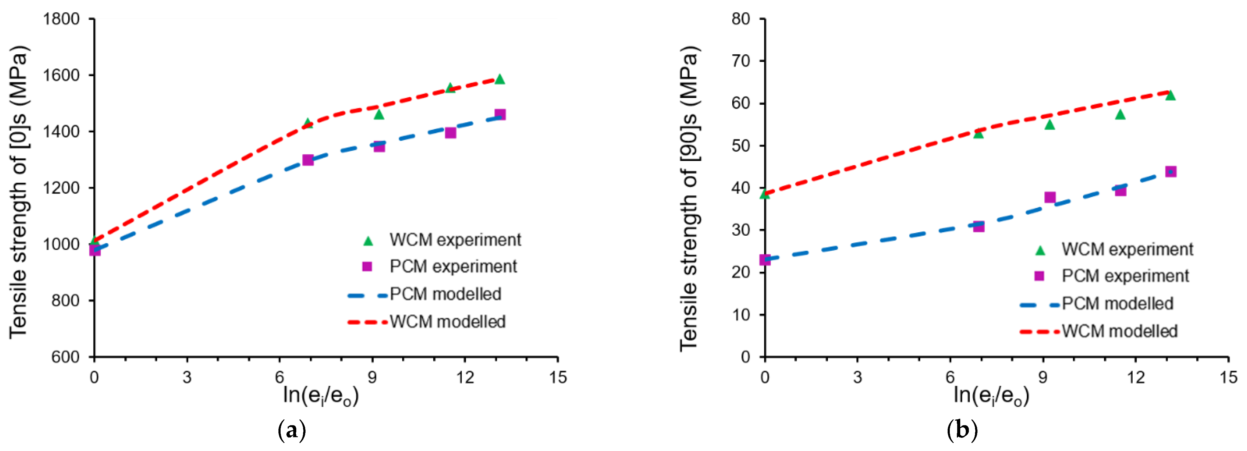
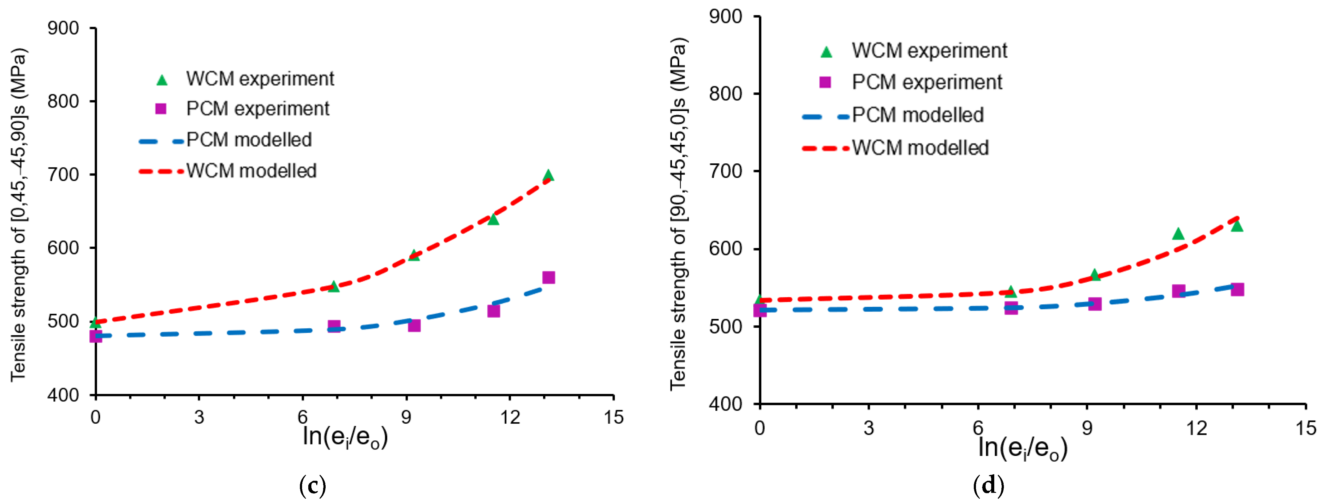
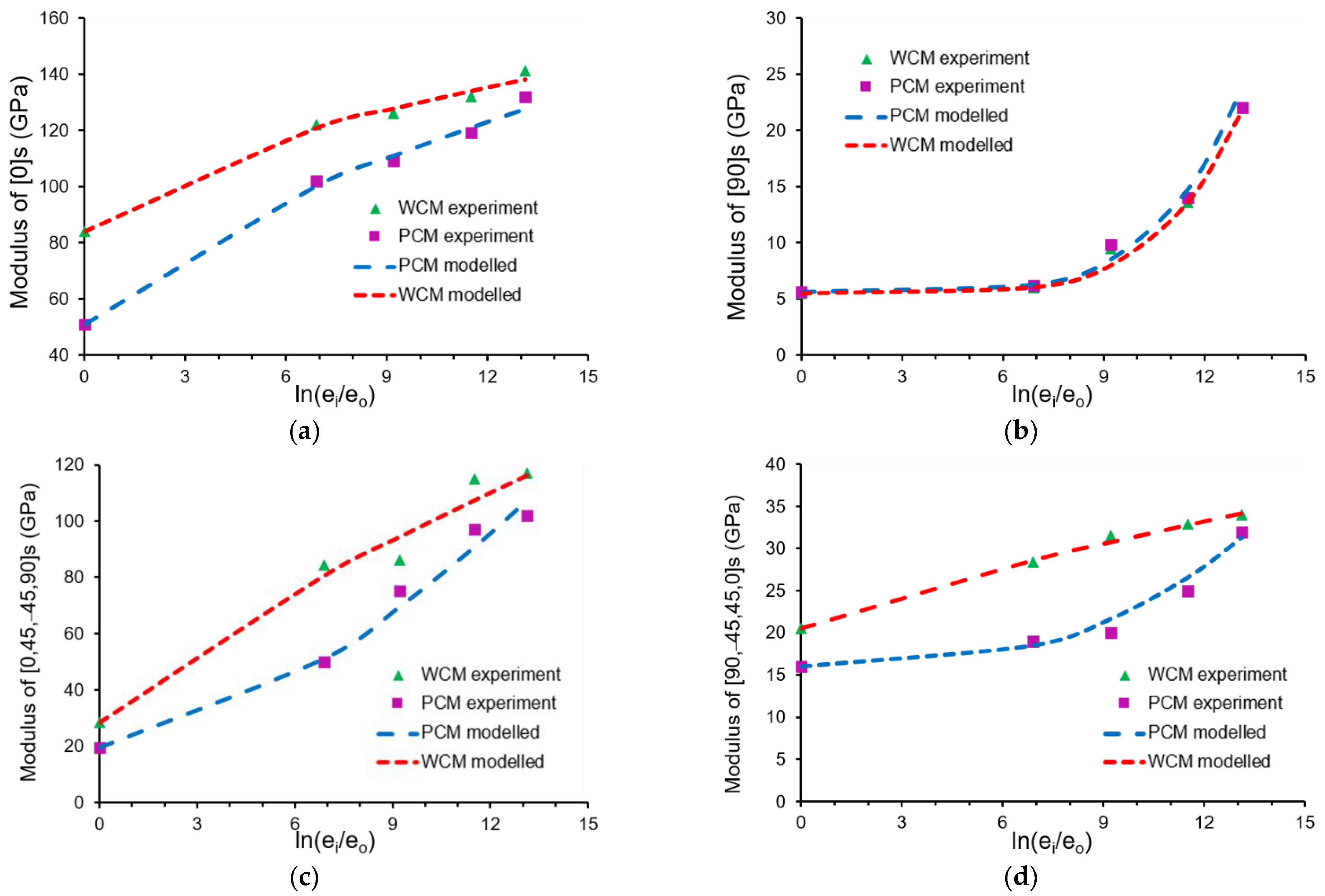
Figure 7 and Figure 8 illustrate the changes in tensile strength and modulus with strain rate for the four configurations. It can be observed that the tensile strength and modulus of the CFRP made using PCM and WCM were at the same level; therefore, both processes can be chosen for automotive part design. As can be seen in Figure 7 and Figure 8, the tensile strength and modulus of the four different stacking sequences produced using two processes showed different extents of strain rate enhancement as a function of the different processes and different configurations. This is mainly because epoxy resin is a strain-rate-sensitive material [11], unlike carbon fiber [13,22]. When the strain rate increases, the time required to respond to the strain decreases, which results in stress localization. Thus, subjecting the whole material to strain requires greater stress, resulting in a higher stress and modulus. Since the response time decreases and the localized stress increases, the materials fracture quickly, resulting in a reduced failure strain. Since the PCM and WCM processes require different epoxies, they show different strain rate sensitivities. Since CFRP is a fiber–resin composite, different fiber orientations exhibit different constraint forces as a function of the resin; therefore, different configurations feature different strain rate sensitivities [11,12,14,23].
To simulate the effect of strain rate, a strain rate sensitivity curve can be plotted. The Yen and Carizzo model is proposed in Equation (1) [24] to describe the effect of strain rate on the strength by introducing a strain rate factor , which has been used in commercial software simulated as a linear effect.
However, from Figure 7 and Figure 8, it can be observed that the strain rate effect was more likely to have been nonlinear; therefore, a modified Yen and Carizzo model is proposed by introducing two factors a and b, as shown in Equations (2) and (3).
where and are the tensile strength and modulus, respectively, at the tested strain rate , and are the tensile strength and modulus, respectively, at the reference strain rate (i.e., the quasi-static strain rate of 0.001 s−1), and a and b are two strain rate factors.
The dotted lines in Figure 7 and Figure 8 demonstrate the results of the proposed model, showing that the modeled data fit the experimental data well, thus highlighting its applicability. The factors a and b are related to a low strain rate (below 10 s−1) and a high strain rate (above 100 s−1), respectively. Accordingly, when a is greater, the material features a higher strain rate sensitivity at a low strain rate; when b is greater, the material features a higher strain rate sensitivity at a high strain rate.
Table 2 illustrates the two strain rate factors for the different configurations made using both processes. In terms of tensile strength, factor a for different configurations decreased in the following order: (0)s > (90)s > typical configuration with a (0) top layer > typical configuration with a (90) top layer, whereas factor b decreased in the following order: typical configuration with a (90) top layer > typical configuration with a (0) top layer > (90)s > (0)s. In terms of modulus, factor a decreased in the following order: (0)s > typical configuration with a (0) top layer > typical configuration with a (90) top layer > (90)s, whereas factor b decreased in the following order: (90)s > typical configuration with a (90) top layer > typical configuration with a (0) top layer > (0)s. Therefore, factors a and b exhibited opposite trends.
Focusing on the tensile strength, it can be observed that the value of factor a for typical configurations was much lower than that of directional configurations, whereas the value of factor b showed the opposite trend. Thus, the sensitive strain rate of typical configurations was higher than that of directional configurations. Previous studies found that the sensitive strain rate of tensile strength for a (±45) configurations is much high than that for (0) and (90) configurations [11,12]. Taniguchi et al. [14] also found that a higher fiber orientation produces a more significant contribution to the strain rate sensitivity of tensile strength. Therefore, the sensitivity strain rate of tensile strength could be related to the angle between the CFRP layers. A higher, more complex angle in CFRP results in a higher value of factor b and, thus, a more sensitive strain rate.
In terms of the modulus, from Figure 8c,d and Table 2, it can be observed that factor a for the directional (0)s configuration was much lower than that for the (90)s configuration, indicating greater sensitivity. Since carbon fiber is a strain rate-insensitive material, and it has a predominant influence on the modulus in (0)s [13], the strain rate sensitivity of the (0)s configuration is lower than that of the (90)s configuration. Comparing the two typical configurations, it can be observed that the sensitive strain rate was decided by the top layer, whereby configurations with a (0) top layer exhibited less sensitivity than configurations with a (90) top layer.
Therefore, different configurations have significant effects on dynamic tensile properties, especially the angle between the layers and the orientation of the top layer. Promisingly, these effects can be represented by factors a and b in the proposed model. In automotive part design, by obtaining the values of factors a and b from dynamic tensile tests, the accuracy of simulation can be significantly improved, and the lightweight effect of CFRP can be maximized.
5. Conclusions
CFRPs manufactured using two processes showed the same level of tensile strength, suggesting that they can both be used in the design of automotive parts.
However, since different resins are used in PCM and WCM, the starting points of fracture for the two processes are different. In PCM, the first fracture occurs at the fiber–resin interface, whereas, in WCM, the first fracture occurs in the resin matrix. This should be considered in automotive design.
The fiber orientation in the top layer partly determines the fracture mode of CFRPs. A (0) layer more easily produces brush failure, whereas a (90) layer typically produces straight failure, and (±45) layers always exhibit shear failure. When the middle layers are the same as the top layer, the fracture mode of the CFRP is the same as the fracture mode of the top layer; however, when the middle layer is (±45), the fracture mode of CFRP is a mixture of top-layer and shear fracture.
Compared with the static performance, the dynamic performance exhibited an enhancement effect on the strength and modulus, whereas it had a decreasing effect on the failure strain. Resins and configurations both exerted an influence on the strain rate sensitivity, whereby resin was the decisive factor. The effect on the stain rate was described using an analytical model by introducing two strain rate factors a and b. The proposed model agreed well with the experimental data, and it can be used in simulations to maximize the lightweight properties of CFRP.
Funding
This research was sponsored by Nanjing Vocational University of Industrial Technology Introduce Talent Research Start-up Funding (YK20-04-04).
Institutional Review Board Statement
Not applicable.
Informed Consent Statement
Not applicable.
Data Availability Statement
Not applicable.
Acknowledgments
The CFRP used in this research was provided by HRC and KOLLER.
Conflicts of Interest
The author declares no conflict of interest.
References
- Hinrichsen, J.; Bautista, C. The challenge of reducing both airframe weight and manufacturing cost. Air Space Eur. 2001, 3, 119–121. [Google Scholar] [CrossRef]
- Wang, J.; Zhao, X. Lightweight research of carbon fiber/epoxy battery box. Fiber Reinf. Plast. /Compos. 2016, 12, 99–102. [Google Scholar] [CrossRef]
- Zhang, C.; Zhu, P.; Feng, Q.; He, J.; Zhou, Q. Optimization study of carbon fiber reinforced plastic vehicle fender. Automot. Eng. 2015, 5, 367–374. [Google Scholar] [CrossRef]
- Jacob, G.C.; Starbuck, J.M.; Fellers, J.F.; Simunovic, S.; Boeman, R.G. Strain rate effects on the mechanical properties of polymer composite materials. J. Appl. Polym. Sci. 2004, 94, 296–301. [Google Scholar] [CrossRef]
- Ma, Z.; Li, W.; Yang, S.; Huang, B.; Tong, S.; Li, C.; Zhao, H.; Ren, L. Strain rate-dependent deformation behaviors of multi-layer carbon fiber reinforced polymer laminates. J. Appl. Polym. Sci. 2021, 138, 50910. [Google Scholar] [CrossRef]
- Zhang, X.; Hao, H.; Shi, Y.; Cui, J.; Zhang, X. Static and dynamic material properties of CFRP/epoxy laminates. Constr. Build. Mater. 2016, 114, 638–649. [Google Scholar] [CrossRef] [Green Version]
- Okoli, O.I. The effects of strain rate and failure modes on the failure energy of fibre reinforced composites. Compos. Struct. 2001, 54, 299–303. [Google Scholar] [CrossRef]
- Duan, S.; Mo, F.; Yang, X.; Tao, Y.; Wu, D.; Peng, Y. Experimental and numerical investigations of strain rate effects on mechanical properties of LGFRP composite. Compos. Part B: Eng. 2016, 88, 101–107. [Google Scholar] [CrossRef]
- Kimura, H.; Itabashi, M.; Kawata, K. Mechanical characterization of unidirectional CFRP thin strip and CFRP cables under quasi-static and dynamic tension. Adv. Compos. Mater. 2001, 10, 177–187. [Google Scholar] [CrossRef]
- Naresh, K.; Shankar, K.; Rao, B.; Velmurugan, R. Effect of high strain rate on glass/carbon/hybrid fiber reinforced epoxy laminated composites. Compos. Part B: Eng. 2016, 100, 125–135. [Google Scholar] [CrossRef]
- Gilat, A.; Goldberg, R.K.; Roberts, G.D. Experimental study of strain-rate-dependent behavior of carbon/epoxy composite. Compos. Sci. Technol. 2002, 62, 1469–1476. [Google Scholar] [CrossRef]
- Wang, Z.; Zhao, G.; Ma, J.; Zhang, J. Experiment study on the strain rate behavior of carbon/epoxy composite materials. Acta Mater. Compos. Sin. 2007, 24, 113–119. [Google Scholar]
- Kwon, J.; Choi, J.; Huh, H.; Lee, J. Evaluation of the effect of the strain rate on the tensile properties of carbon–epoxy composite laminates. J. Compos. Mater. 2016, 51, 3197–3210. [Google Scholar] [CrossRef]
- Taniguchi, N.; Nishiwaki, T.; Kawada, H. Tensile strength of unidirectional CFRP laminate under high strain rate. Adv. Compos. Mater. 2007, 16, 167–180. [Google Scholar] [CrossRef]
- Oya, N.; Hamada, H. Mechanical properties and failure mechanisms of carbon fibre reinforced thermoplastic laminates. Compos. Part A Appl. Sci. Manuf. 1997, 28, 823–832. [Google Scholar] [CrossRef]
- Azadi, M.; Sayar, H.; Ghasemi-Ghalebahman, A.; Jafari, S.M. Tensile loading rate effect on mechanical properties and failure mechanisms in open-hole carbon fiber reinforced polymer composites by acoustic emission approach. Compos. Part B Eng. 2019, 158, 448–458. [Google Scholar] [CrossRef]
- Maekawa, Z.-I.; Hamada, H.; Kitagawa, T.; Lee, K. The difference of Fracture Behaviour between T300 and T800 Quasi-Isotropic Composites. Adv. Compos. Lett. 1992, 1. [Google Scholar] [CrossRef]
- Naresh, K.; Shankar, K.; Velmurugan, R. Reliability analysis of tensile strengths using Weibull distribution in glass/epoxy and carbon/epoxy composites. Compos. Part B Eng. 2018, 133, 129–144. [Google Scholar] [CrossRef]
- Wu, W.; Liu, Q.; Wu, L. Mechanical Properties of Carbon Fiber Reinforced Plastic Structures with Different Forming Process. Fiber Reinf. Plast./Compos. 2017, 10, 23–28. [Google Scholar] [CrossRef]
- Rao, P.S.; Hardiman, M.; O’Dowd, N.P.; Sebaey, T.A. Comparison of progressive damage between thermoset and thermoplastic CFRP composites under in-situ tensile loading. J. Compos. Mater. 2020, 55, 1473–1484. [Google Scholar] [CrossRef]
- Johnson, W.; Masters, J.; Subramanian, S.; Reifsnider, K.; Stinchcomb, W. Tensile Strength of Unidirectional Composites: The Role of Efficiency and Strength of Fiber-Matrix Interface. J. Compos. Technol. Res. 1995, 17, 289. [Google Scholar] [CrossRef]
- Zhou, Y.; Wang, Y.; Xia, Y.; Jeelani, S. Tensile behavior of carbon fiber bundles at different strain rates. Mater. Lett. 2010, 64, 246–248. [Google Scholar] [CrossRef]
- Sadeghian, P.; Rahai, A.R.; Ehsani, M.R. Effect of Fiber Orientation on Nonlinear Behavior of CFRP Composites. J. Reinf. Plast. Compos. 2008, 28, 2261–2272. [Google Scholar] [CrossRef]
- Yen, C.F. Ballistic impact modelling of composite materials. In Proceedings of the 7th internal LS-DYNA user conference, Dearborn, MI, USA, 19 May 2002; pp. 15–26. [Google Scholar]
Figure 1.
Specimen geometry in mm: (a) quasi-static test specimen; (b) dynamic test specimen.

Figure 2.
Tensile test machines: (a) electronic universal testing machine; (b) large dynamic testing machine.
Figure 2.
Tensile test machines: (a) electronic universal testing machine; (b) large dynamic testing machine.

Figure 3.
Tensile stress–strain curve and fracture images of (0)s configuration made using (a) PCM and (b) WCM.
Figure 3.
Tensile stress–strain curve and fracture images of (0)s configuration made using (a) PCM and (b) WCM.

Figure 4.
Tensile stress–strain curve and fracture images of (90)s configuration made using (a) PCM and (b) WCM.
Figure 4.
Tensile stress–strain curve and fracture images of (90)s configuration made using (a) PCM and (b) WCM.

Figure 5.
Tensile stress–strain curve and fracture images of typical configurations made using both processes: (a) (0/45/−45/90)s made using PCM; (b) (0/45/−45/90)s made using WCM; (c) (90/−45/45/0)s made using PCM; (d) (90/−45/45/0)s made using WCM.
Figure 5.
Tensile stress–strain curve and fracture images of typical configurations made using both processes: (a) (0/45/−45/90)s made using PCM; (b) (0/45/−45/90)s made using WCM; (c) (90/−45/45/0)s made using PCM; (d) (90/−45/45/0)s made using WCM.

Figure 6.
Fracture mechanism and fracture images of four configurations made using PCM and WCM: (a) (0)s; (b) [0/45/−45/90]s; (c) (90)s; (d) [90/−45/45/0]s.
Figure 6.
Fracture mechanism and fracture images of four configurations made using PCM and WCM: (a) (0)s; (b) [0/45/−45/90]s; (c) (90)s; (d) [90/−45/45/0]s.


Figure 7.
Effect of strain rate on tensile strength of different configurations: (a) (0)s; (b) (90)s; (c) [0/45/−45/90]s; (d) [90/−45/45/0]s.
Figure 7.
Effect of strain rate on tensile strength of different configurations: (a) (0)s; (b) (90)s; (c) [0/45/−45/90]s; (d) [90/−45/45/0]s.


Figure 8.
Effect of strain rate on modulus of different configurations: (a) (0)s; (b) (90)s; (c) [0/45/−45/90]s; (d) [90/−45/45/0]s.
Figure 8.
Effect of strain rate on modulus of different configurations: (a) (0)s; (b) (90)s; (c) [0/45/−45/90]s; (d) [90/−45/45/0]s.


Table 1.
Tensile test matrix used in this study.
| Tensile Test Conditions | (0)s | (90)s | [0/45/−45/90]s | [90/−45/45/0]s | ||
|---|---|---|---|---|---|---|
| Quasi-static tensile | PCM | 0.001 s−1 | √ | √ | √ | √ |
| WCM | ||||||
| Dynamic tensile | PCM | 1 s−1 | √ | √ | √ | √ |
| WCM | ||||||
| PCM | 10 s−1 | √ | √ | √ | √ | |
| WCM | ||||||
| PCM | 100 s−1 | √ | √ | √ | √ | |
| WCM | ||||||
| PCM | 500 s−1 | √ | √ | √ | √ | |
| WCM | ||||||
Table 2.
Values of the two strain rate factors for different configurations made using different processes.
Table 2.
Values of the two strain rate factors for different configurations made using different processes.
| Configurations | (0)s | (90)s | [0/45/−45/90]s | [90/−45/45/0]s | ||
|---|---|---|---|---|---|---|
| Tensile strength | PCM | a | 0.097 | 0.0239 | 0.0000417 | 0.00000479 |
| b | 0.62 | 1.41 | 3.15 | 3.67 | ||
| WCM | a | 0.145 | 0.091 | 0.0015 | 0.0000187 | |
| b | 0.53 | 0.75 | 2.16 | 3.60 | ||
| Modulus | PCM | a | 0.254 | 0.0000053 | 0.075 | 0.00067 |
| b | 0.69 | 5.17 | 1.59 | 2.82 | ||
| WCM | a | 0.137 | 0.0000036 | 0.384 | 0.081 | |
| b | 0.60 | 5.29 | 0.81 | 0.82 | ||
Publisher’s Note: MDPI stays neutral with regard to jurisdictional claims in published maps and institutional affiliations. |
© 2021 by the author. Licensee MDPI, Basel, Switzerland. This article is an open access article distributed under the terms and conditions of the Creative Commons Attribution (CC BY) license (https://creativecommons.org/licenses/by/4.0/).
Share and Cite
MDPI and ACS Style
Yang, Y. Dynamic Tensile Properties of CFRP Manufactured by PCM and WCM: Effect of Strain Rate and Configurations. Crystals 2021, 11, 1491. https://0-doi-org.brum.beds.ac.uk/10.3390/cryst11121491
AMA Style
Yang Y. Dynamic Tensile Properties of CFRP Manufactured by PCM and WCM: Effect of Strain Rate and Configurations. Crystals. 2021; 11(12):1491. https://0-doi-org.brum.beds.ac.uk/10.3390/cryst11121491
Chicago/Turabian StyleYang, Yujin. 2021. "Dynamic Tensile Properties of CFRP Manufactured by PCM and WCM: Effect of Strain Rate and Configurations" Crystals 11, no. 12: 1491. https://0-doi-org.brum.beds.ac.uk/10.3390/cryst11121491
Note that from the first issue of 2016, this journal uses article numbers instead of page numbers. See further details here.