
Ferroelectric Liquid Crystal Compound Lens Based on Pancharatnam–Berry Phase
by
 ,
,
Ying Ma
1,*, 
Mingkui Yin
1,
Yuhang Shan
1,
Vladimir G. Chigrinov
2,
Hoi-Sing Kwok
3 and
Jianlin Zhao
1 1
Key Laboratory of Light Field Manipulation and Information Acquisition, Ministry of Industry and Information Technology, School of Physics Science and Technology, Northwestern Polytechnical University, Xi’an 710129, China
2
Nanjing Nanhui Intelligent Optical Sensing and Manipulation Research Institute Co., Ltd., Nanjing 210093, China
3
State Key Laboratory (SKL) on Advanced Displays and Optoelectronics Technologies, Department of Electronic and Computer Engineering, Hong Kong University of Science and Technology, Kowloon 999077, Hong Kong
*
Author to whom correspondence should be addressed.
Crystals 2022, 12(2), 231; https://0-doi-org.brum.beds.ac.uk/10.3390/cryst12020231
Submission received: 23 December 2021
/
Revised: 28 January 2022
/
Accepted: 31 January 2022
/
Published: 8 February 2022
(This article belongs to the Special Issue Liquid Crystals in China)
Abstract
:We report a ferroelectric liquid crystal (FLC) compound lens based on the Pancharatnam–Berry (PB) phase. The phase of the FLC compound lens is an integration of polarization grating and a PB lens. Thus, when light passes through an FLC compound lens, the output light’s polarization handedness will be changed accordingly. In this case, FLC compound lenses can function as concave/convex lenses with spatially separated output light and rapid transmittance tunability. The FLC compound lenses were fabricated using a single-step holographic exposure system, based on a spatial light modulator working as numerous phase retarders. Photosensitive azo-dye material was used as the aligning layer. The output light transmittance of the FLC compound lens can be operated at 150 μs. Our results achieve the potential applications on various displays and augmented reality.
1. Introduction
The lens, as one of the most important optical elements, is widely used in our daily life for optical usages, such as the eyeglass, camera objective, microscope and telescope [1]. Compared with conventional refractive lenses, liquid crystal (LC) lenses show good potential, with the features of controllable birefringence and refractive indices, as well as high integration and compact size. In recent years, Pancharatnam–Berry (PB) phase devices have been regarded as the fourth generation of optical elements in the optical science and engineering community, where the circular polarization-dependent devices are well utilized, including the capacity of optical communication systems [2,3], and virtual and augmented reality displays [4,5,6,7]. The PB phase devices fabricated with liquid crystals (LCs) are potential candidates because of their inherent photoelectric properties, large optical birefringence and controllable continuous orientation [8,9]. Several well-known optical elements use the PB phase, including the PB lens [10,11], polarization grating (PG) [12] and the q-plate [13]. They are widely used for the shaping of various wavefronts, such as a helical wavefront for vortex beams [9] and vector beams [14], as well as laser beam shaping [15]. With the help of LC photoalignment technology [16,17], it is becoming possible to realize complex micro-sized LC structures. Ferroelectric liquid crystals (FLCs) utilizing photo-alignment technology [16,18,19,20] represent a promising way to produce LC PB devices with a microsecond response [21], which is at least two orders of magnitude higher than common nematic liquid crystals. Several mask-free photopatterning systems have been developed. A DMD (digital mirror device) [21,22,23,24] and direct laser writing [25,26,27] were reported, but failed to provide single-step exposure. Recently, a single-step exposure system was used to fabricate PB gratings and q-plates based on a spatial light modulator (SLM) [28]. A fast-switching PB lens fabricated with ferroelectric liquid crystals (FLCs), based on an SLM exposure system, was also realized [21].
For the general LC PB lens, bifocal property has been realized according to the different handedness of the incident circularly polarized light [29]. In this paper, we have demonstrated an FLC compound lens, and deformed helix FLCs (DHFLCs) were selected because they can offer a fast response, continuously changing light transmittance [30] and a defect-free structure. Different from the conventional FLC PB lens, the proposed FLC compound lens can switch between two spatially separated focuses, manipulating light by the generation and modulation of the PB phase [31,32], with the fast response property of FLCs. With these special optical properties, the lens shows good potential to be used in many modern applications, such as polarizing imaging [33,34], micro particle manipulation [35] and multifocal cameras that can control the focus of the generated beams or the positions of the generated light paths [36]. The diffraction efficiency of FLC compound lenses can be rapidly changed with a switching-on time of 150 at . The output light passing through an FLC lens shows precise, spatial separation with different focuses, which are in good agreement with the theoretical results. Light beam separation angles and focuses can be designed based on different applications.
2. Materials and Methods
2.1. Materials
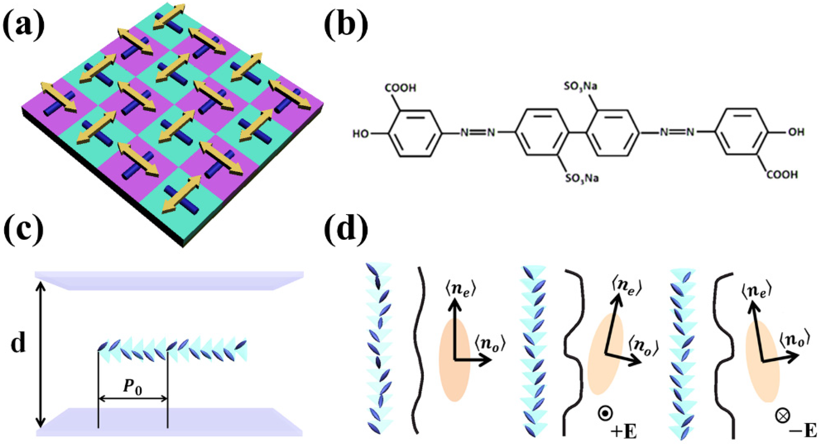
With the help of the realization of the photoalignment method, a complex FLC aligning structure became possible. A polarization photosensitive alignment sulphonic azo-dye (SD1) was chosen as the aligning material for its flexible anchoring energy, lack of mechanical damage and minimized unwanted electronic charges. Under exposure from a polarized light source with a UV-to-blue spectrum, the SD1 molecule tends to orient perpendicularly to the polarization of the incident light. Its working principle and molecular structure are shown in Figure 1a,b. The blue cylindrical objects at the bottom represent liquid crystal molecules, whereas the yellow arrows above represent the polarization state of light, and the molecular orientations in different color regions can be different when polarizations of incident light are region dependent.
In this work, DHFLCs [37] were selected because they can offer a fast response and continuously changing light transmittance [21,30,38]. In particular, DHFLC 587 (from P.N. Lebedev Physical Institute of Russian Academy of Sciences, Moscow, Russia) was selected for its high transmission in the visible spectrum. The phase transition sequence of this LC when heated up from the solid crystalline phase is Cr→12 °C → SmC* → 110 °C → SmA* → 127 °C → Is, while cooling from smectic C* phase crystallization occurs around −10–15 °C. The spontaneous polarization Ps and the tilt angle θ at room temperature are 150 nC/cm2 and 36.5°, respectively. ne and no are 1.67 and 1.57 measured at room temperature. Two optically flat indium tin oxide-coated glass plates were used for preparing a sandwich-type sample holder. SD1 was coated by a spin coater at 3000 r/min for 30 s. Spacers were used to form the sandwich-like structure. The designed pattern was exposed on the cell using an exposure system, which will be illustrated in the following section. FLC was then filled into the cell when the cell was heating up to its isotropic temperature. The cell thickness was 3 μm, calculated in order to satisfy the half wave condition using Δnd = λ/2, where Δn represents the birefringence and λ = 633 nm. In the schematic of a typical DHFLC cell shown in the upper picture of Figure 1c, when there is no electric field, a helix exists with helix pitch denoted as P0 and one important requirement for DHF effect existence is . When there is an external electric field to DHFLC molecules, the fast axis changes in accordance with the absolute value of the electric field. The principle of birefringence of a DHFLC is shown in Figure 1d. The long axis of the index ellipsoid is along the z-axis in the absence of an electric field. The refractive index ellipsoid rotates in the plane perpendicular to the electric field, and its long axis is offset relative to the z-axis when the electric field exists. When the polarity of the electric field is positive, the DHFLC molecules are aligned along the cone surface to the right, and the refractive index ellipsoid rotates to the right. The DHFLC molecules and the refractive index ellipsoid rotate to the other side when the polarity of the electric field is opposite. The birefringence is described by the following equation:
where and can be considered as and without the electric field. , and the azimuth angle φ change in the presence of the electric field. Transmittance can then be calculated based on the parameters of the certain FLC material [39].
2.2. Fabrication Method
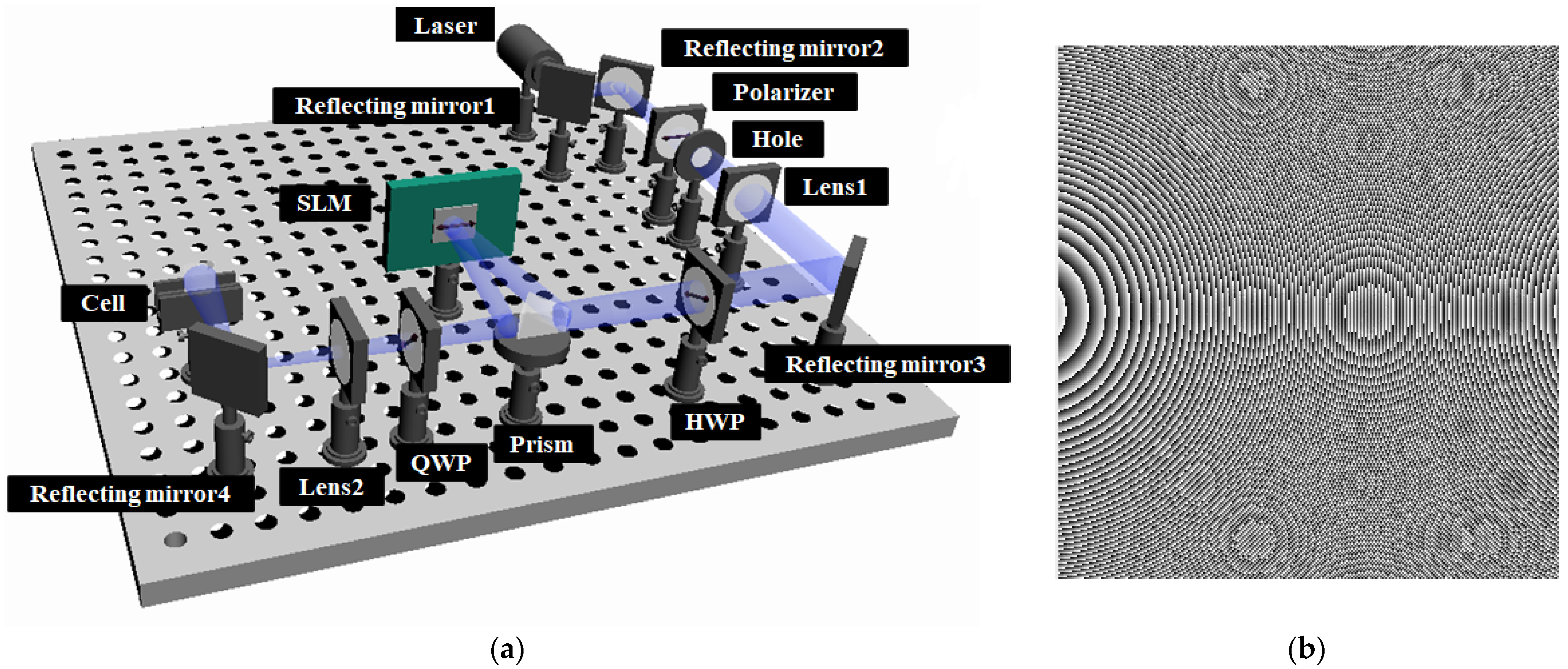
The exposure system based on SLM is depicted in Figure 2a, which consists of a 450 nm laser, two optical lenses (Lens1 and Lens2), a half-wave plate (HWP), a right-angle prism, an SLM and a quarter-wave plate (QWP). Its working principal is to use an SLM as several light beam retarders to generate regional, polarized output light, which is described in detail in our previous work [39]. The polarizations of output light from the SLM can be precisely controlled by the electric field loaded through computer-designed grayscale images. The final polarized output light can be exposed on the SD1-coated liquid crystal cells.
2.3. Theory
Both the PB lens and the liquid crystal PGs are PB phase liquid crystal devices. Their phases are described by φ1 and φ2, respectively, as follows:
where λ is the wavelength of the incident light, f is the focus length of the lens, Λ is the period of the polarization grating, and x and y are the coordinates of the wavefront. Through φ1 and φ2, we can observe that the lens can diverge or converge the light and the polarization grating can change the direction of the light. By superimposing φ1 and φ2, it is possible to realize the integration of the two functions. The phase of the integrated device is expressed as φ in the following:
The integrated device works under half-wave conditions, so a phase delay of π will be achieved. The right-handed circularly polarized and the left-handed polarized light can be represented by JR and JL, respectively, in the following:
When passing through the compound lens, the polarization and phase will be changed as follows:
where θ is the angle between the long axis of liquid crystal and the x-axis. According to the existing literature, φ = 2θ.
With phase φ, we can simulate the transmission process of light; Azimuthal angle θ is used as the aligning angle for the designed compound lenses. By the relationship between output light polarizations and the gray values that we loaded onto the SLM, a grayscale image can be generated to realize the designed output light polarization distributions for aligning LC molecule directions. The grayscale image is shown in Figure 2b.
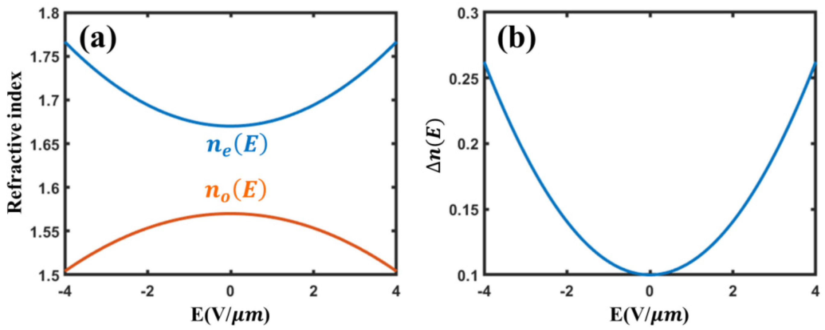
For a DHFLC cell operated in the low-electric-field regime, which means under the helix unwinding electric field (~4 V/μm), the in-plane refractive indices induced by the electric field are dominated by the Kerr-like nonlinear terms, represented as ne(E) = ne + k1E2, no(E) = no + k2E2, where ne (no) is the zero-field refractive index of extraordinary (ordinary) waves, and the electrooptic coupling coefficients k1 and k2 depend on the smectic tilt angle θ, the spontaneous ferroelectric polarization Ps and the dielectric susceptibility of the Goldstone mode χE. The parameters can be estimated as follows: ne ≈ 1.67, no ≈ 1.57, k1 ≈ 6.03 × 10⁻³ μm2/V2, k2 ≈ −4.12 × 10⁻³ μm2/V2 [40]. Figure 3 shows the simulation of refractive index and birefringence with the changing electric field. The birefringence can vary between 0.1 and 0.26 under an electric field of 0 to 4 V/μm.
When left circularly polarized light passes through the compound lens, complex amplitude can be represented as follows:
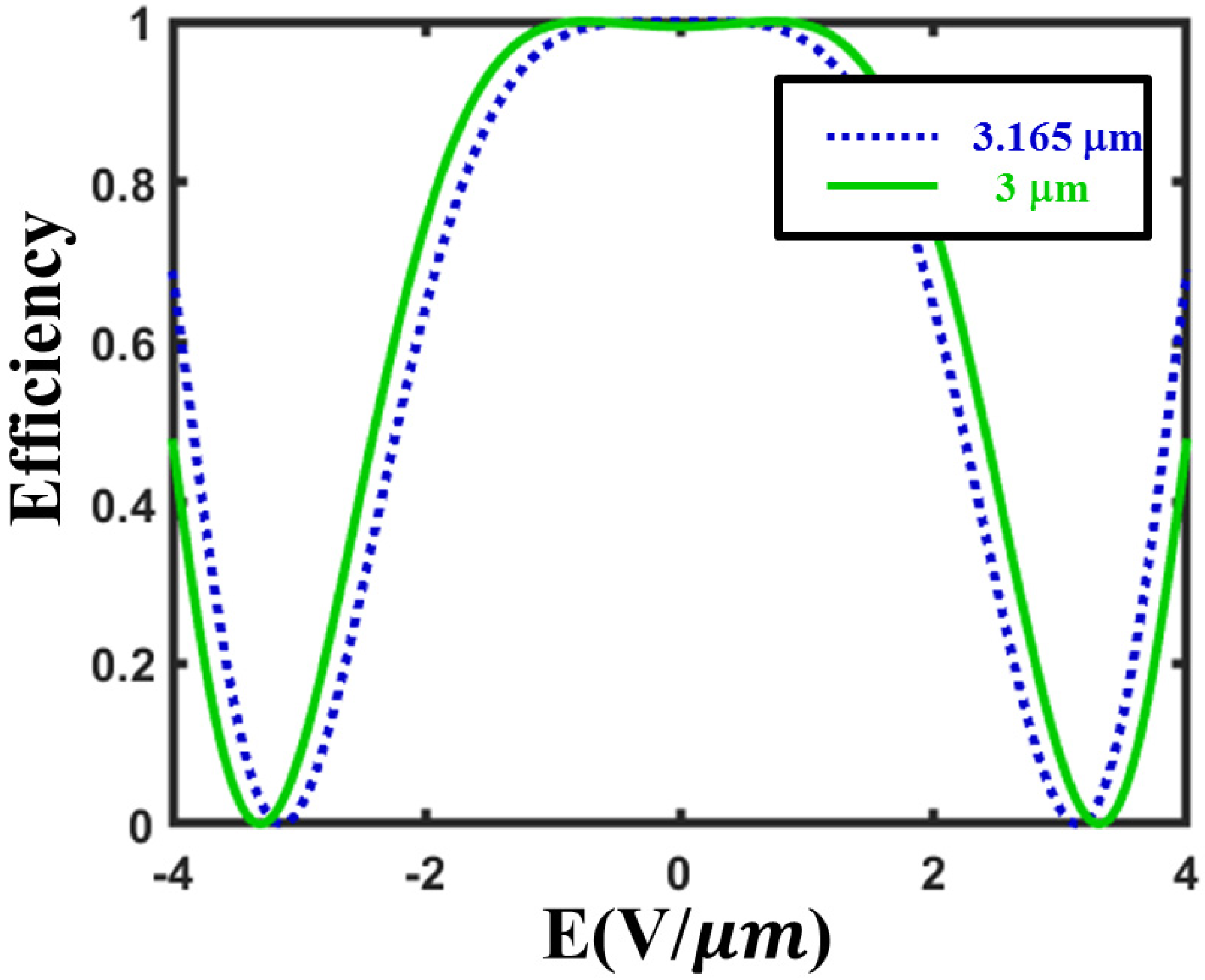
where Γ = 2πΔn(E)d/λ. Then efficiency of the compound lens can be calculated as η = P2/(P1 + P2), where P1 and P2 are power of E1 and E2. From the simulation result in Figure 4, when cell thickness d satisfies the half-wave condition around 3.165 μm, the theoretical efficiency can reach its maximum of 100%. However, it is not easy to fabricate this precise cell thickness as this will decrease the efficiency. As we apply an electric field of 0.75 V/μm, we can obtain 100% efficiency with a fast response by the DHFLC material.
3. Results and Discussion
For DHFLC 587, the switching time can be calculated using the following equation:
where rotational viscosity γφ = 0.2 Pa⋅s and the helix pitch P0 = 0.18 μm at 22 °C. The theoretical switching time is around 160 μs. In our previous work, switching time was experimentally measured at 150 μs [21].
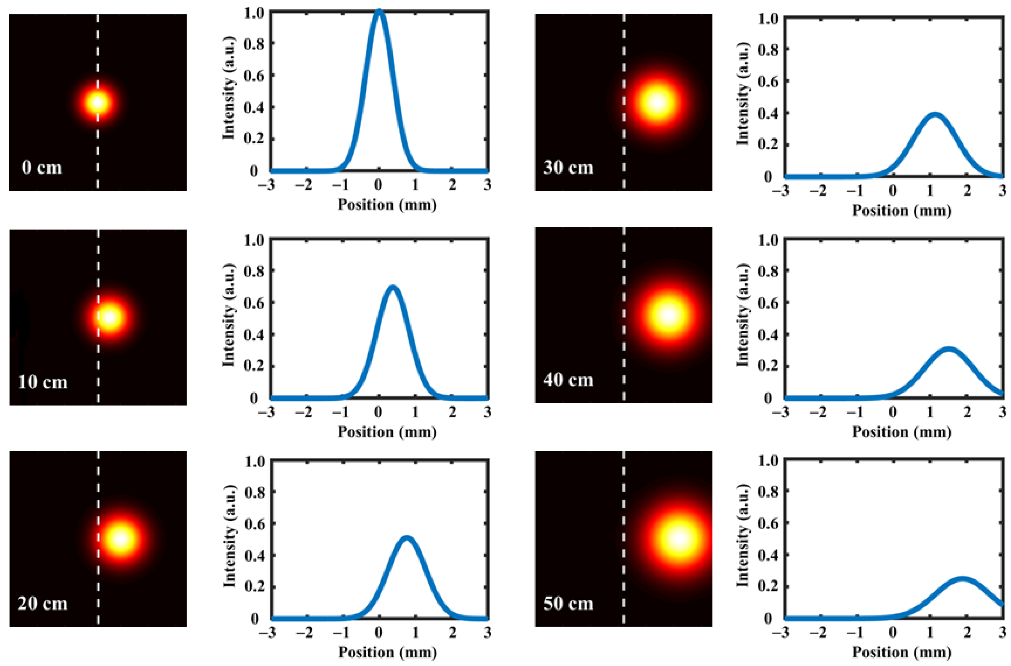
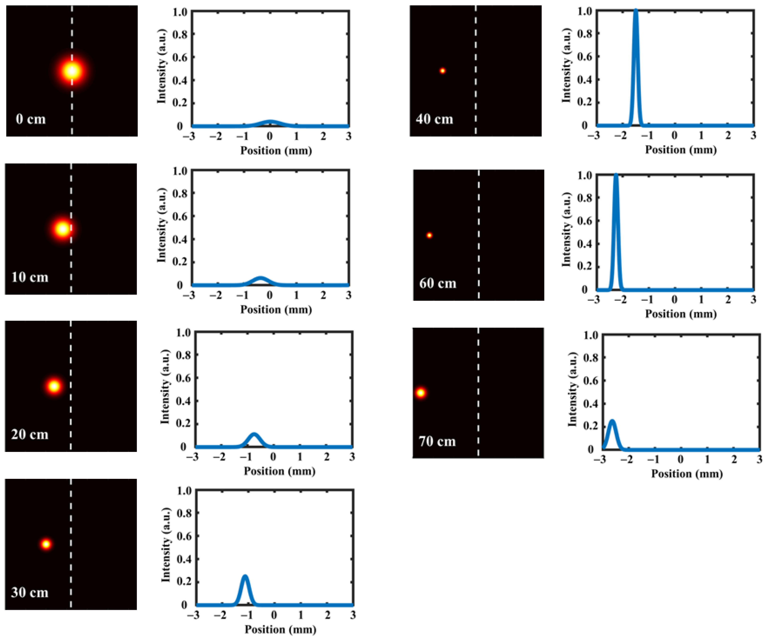
In the simulation, we set the focal length of the lens to 50 cm and the period of the grating to 42 μm. When the incident light is right-handed circularly polarized light, the output light is left-handed circularly polarized with phase φ, and the simulation results are shown in Figure 5. The light field and corresponding intensity distribution were captured at 0 cm, 10 cm, 20 cm, 30 cm, 40 cm and 50 cm behind the lens. It can be observed that as the propagation distance increases, the spot diameter increases and the light intensity decreases, showing a Gaussian distribution, so the light is divergent. At the same time, the light is diffracted to the +1st order. When the incident light is left-handed circularly polarized light, the output light is right-handed circularly polarized with phase –φ. The simulation results are depicted in Figure 6. We obtain the light field and intensity distribution at 0 cm, 10 cm, 20 cm, 30 cm, 40 cm, 60 cm and 70 cm behind the lens. As the propagation distance increases, the diameter of the light spot becomes smaller first and then larger, and the intensity becomes larger first and then smaller. When the distance is less than the focus length of 50 cm, the spot diameter decreases and the intensity increases gradually. When the distance is greater than the focus length of 50 cm, the spot diameter increases and the intensity decreases gradually. The case of the distance of 50 cm is not given here, because, at this position, the light field becomes an ideal point with a diameter of zero and the intensity is infinite. In this case, the light is convergent and diffracted to −1st order. In summary, the integrated device has both the function of a lens and polarization grating.
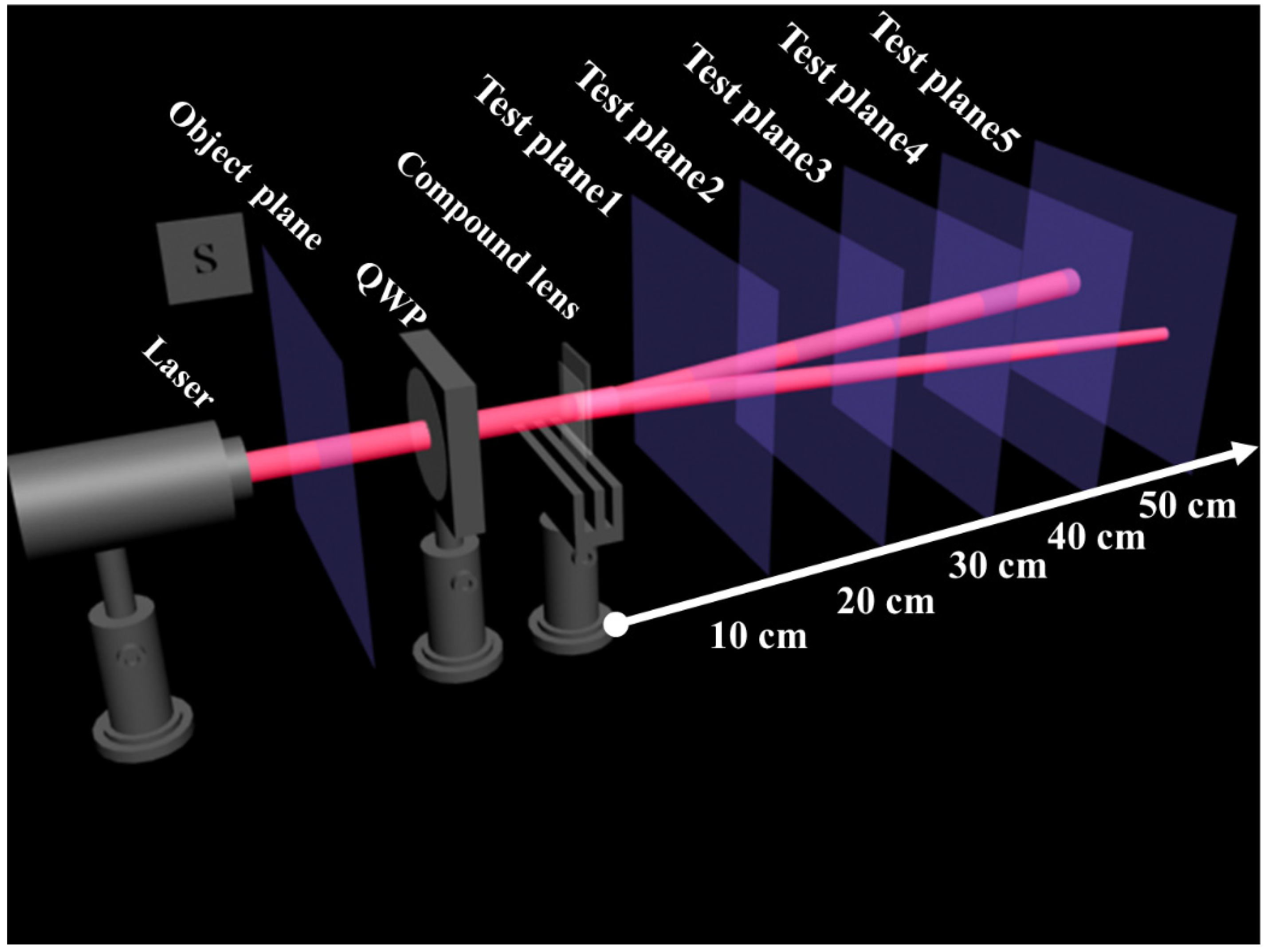
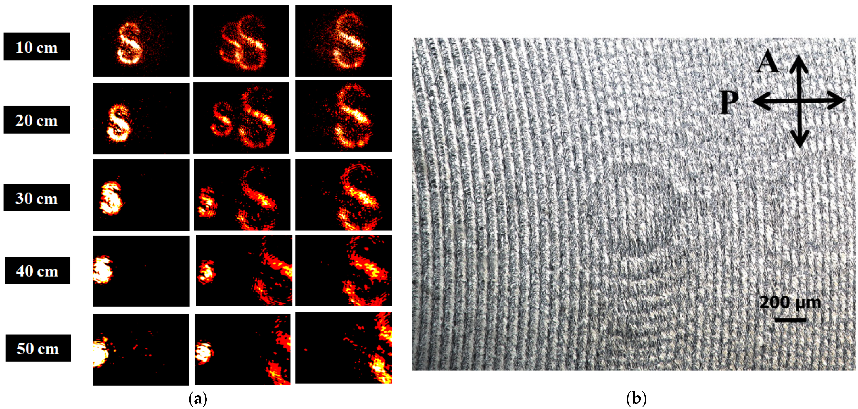
In the experiment, we used FLC587 to fabricate the compound PB lens, and the cell gap was maintained at 3 μm to meet the half-wave condition. The optical setup is illustrated in Figure 7, where an object “S” is placed before a QWP used to manipulate incident light polarizations. The micrograph of the fabricated lens is shown in Figure 8b. We tested the output light performance at the distances of 10 cm, 20 cm, 30 cm, 40 cm and 50 cm away from the lens using left-handed circularly polarized light, linearly polarized light and right-handed circularly polarized light, respectively. As shown in Figure 8a, the figures on the left side were captured under the condition of left-handed circularly polarized input light. The size of object “S” became smaller as the distance between the lens and the camera increased. The results for the right-handed circularly polarized input light are the opposite. Since linearly polarized light can be seen as a superposition of left-handed circularly polarized light and right-handed circularly polarized light, in the case of linear polarization, the output light will diverge and converge at the same time, as shown in the middle figures of Figure 8a. We can observe that the experimental results are in good agreement with the theoretical results.
4. Conclusions
In conclusion, we have demonstrated a DHFLC compound lens whose phase is an integration of a PB lens and polarization grating. We used a single-step holographic exposure setup based on an SLM as a polarization controller at the pixel level to realize continuous LC orientation. The light field and intensity distributions for different distances between the FLC lens and the camera were simulated under the input light of left-handed and right-handed circular polarizations. The experiments were conducted under the same conditions, with good agreement with the simulation results. Furthermore, once illuminated by a linearly polarized beam, the output light could propagate towards two directions around the central axis possessing two opposite states, namely, convergent and divergent. The DHFLC compound lenses provided a fast response time of 150 µs at 2 V/µm. These optical features make them suitable for applications in imaging, display, beam manipulation and various optical setups that require a fast response.
Author Contributions
Conceptualization, Y.M. and M.Y.; methodology, Y.M., M.Y. and Y.S.; software, M.Y. and Y.S.; writing—review and editing, J.Z.; supervision, V.G.C., H.-S.K. and J.Z. All authors have read and agreed to the published version of the manuscript.
Funding
This research was funded by National Key R&D Program of China, grant number 2017YFA0303800 and National Science Foundation of China (NSFC), grant number 61805202.
Institutional Review Board Statement
Not applicable.
Informed Consent Statement
Not applicable.
Data Availability Statement
All the data is contained within this article.
Conflicts of Interest
The authors declare no conflict of interest.
References
- Naumov, A.F.; Loktev, M.Y.; Guralnik, I.R.; Vdovin, G. Liquid-crystal adaptive lenses with modal control. Opt. Lett. 1998, 23, 992–994. [Google Scholar] [CrossRef] [Green Version]
- Bozinovic, N.; Yue, Y.; Ren, Y.; Tur, M.; Kristensen, P.; Huang, H.; Willner, A.E.; Ramachandran, S. Terabit-Scale Orbital Angular Momentum Mode Division Multiplexing in Fibers. Science 2013, 340, 1545–1548. [Google Scholar] [CrossRef] [Green Version]
- Lei, T.; Zhang, M.; Li, Y.; Jia, P.; Liu, G.N.; Xu, X.; Li, Z.; Min, C.; Lin, J.; Yu, C.; et al. Massive individual orbital angular momentum channels for multiplexing enabled by Dammann gratings. Light. Sci. Appl. 2015, 4, e257. [Google Scholar] [CrossRef]
- Chen, H.; Weng, Y.; Xu, D.; Tabiryan, N.V.; Wu, S.-T. Beam steering for virtual/augmented reality displays with a cycloidal diffractive waveplate. Opt. Express 2016, 24, 7287–7298. [Google Scholar] [CrossRef] [Green Version]
- Zhan, T.; Lee, Y.-H.; Wu, S.-T. High-resolution additive light field near-eye display by switchable Pancharatnam–Berry phase lenses. Opt. Express 2018, 26, 4863–4872. [Google Scholar] [CrossRef]
- Chen, H.-S.; Wang, Y.-J.; Chen, P.-J.; Lin, Y.-H. Electrically adjustable location of a projected image in augmented reality via a liquid-crystal lens. Opt. Express 2015, 23, 28154–28162. [Google Scholar] [CrossRef] [PubMed]
- Moon, S.; Lee, C.-K.; Nam, S.-W.; Jang, C.; Lee, G.-Y.; Seo, W.; Sung, G.; Lee, H.-S.; Lee, B. Augmented reality near-eye display using Pancharatnam-Berry phase lenses. Sci. Rep. 2019, 9, 1–10. [Google Scholar] [CrossRef] [PubMed]
- Hecht, E. Optics, 3rd ed.; Addison-Wesley: White Plains, NY, USA, 1998. [Google Scholar]
- Chen, P.; Wei, B.-Y.; Ji, W.; Ge, S.-J.; Hu, W.; Xu, F.; Chigrinov, V.; Lu, Y.-Q. Arbitrary and reconfigurable optical vortex generation: A high-efficiency technique using director-varying liquid crystal fork gratings. Photonics Res. 2015, 3, 133. [Google Scholar] [CrossRef]
- Li, T.; Yang, Y.; Liu, X.; Wu, Y.; Zhou, Y.; Huang, S.; Li, X.; Huang, H. Enhanced optical edge detection based on a Pancharatnam–Berry flat lens with a large focal length. Opt. Lett. 2020, 45, 3681. [Google Scholar] [CrossRef]
- Jiang, M.; Guo, Y.; Yu, H.; Zhou, Z.; Turiv, T.; Lavrentovich, O.D.; Wei, Q. Low f -Number Diffraction-Limited Pancharatnam–Berry Microlenses Enabled by Plasmonic Photopatterning of Liquid Crystal Polymers. Adv. Mater. 2019, 31, e1808028. [Google Scholar] [CrossRef]
- Kim, J.; Oh, C.; Escuti, M.J.; Hosting, L.; Serati, S. Wide-angle nonmechanical beam steering using thin liquid crystal polarization gratings. In Advanced Wavefront Control: Methods, Devices, and Applications VI; SPIE: Bellingham, WA, USA, 2008; Volume 7093, p. 709302. [Google Scholar] [CrossRef]
- Tam, A.M.W.; Fan, F.; Du, T.; Hu, W.; Zhang, W.; Zhao, C.; Wang, X.; Ching, K.-L.; Li, G.; Luo, H.; et al. Bifocal Optical-Vortex Lens with Sorting of the Generated Nonseparable Spin-Orbital Angular-Momentum States. Phys. Rev. Appl. 2017, 7, 034010. [Google Scholar] [CrossRef]
- Huang, B.; Wang, Q.; Jiang, G.; Yi, J.; Tang, P.; Liu, J.; Zhao, C.; Luo, H.; Wen, S. Wavelength-locked vectorial fiber laser manipulated by Pancharatnam-Berry phase. Opt. Express 2017, 25, 30–38. [Google Scholar] [CrossRef] [PubMed]
- Jiang, M.; Yu, H.; Feng, X.; Guo, Y.; Chaganava, I.; Turiv, T.; Lavrentovich, O.D.; Wei, Q.-H. Liquid Crystal Pancharatnam–Berry Micro-Optical Elements for Laser Beam Shaping. Adv. Opt. Mater. 2018, 6, 1800961. [Google Scholar] [CrossRef]
- Chigrinov, V.G.; Kozenkov, V.M.; Kwok, H.S. Photoalignment of Liquid Crystalline Materials: Physics and Applications; John Wiley & Sons: Chichester, UK, 2008; Volume 17. [Google Scholar]
- Yaroshchuk, O.; Reznikov, Y. Photoalignment of liquid crystals: Basics and current trends. J. Mater. Chem. 2011, 22, 286–300. [Google Scholar] [CrossRef]
- Srivastava, A.K.; Wang, X.Q.; Gong, S.Q.; Shen, D.; Lu, Y.Q.; Chigrinov, V.; Kwok, H.S. Micro-patterned photo-aligned ferroelectric liquid crystal Fresnel zone lens. Opt. Lett. 2015, 40, 1643–1646. [Google Scholar] [CrossRef] [Green Version]
- Huang, D.; Pozhidaev, E.; Chigrinov, V.; Cheung, H.; Ho, Y.; Kwok, H. Photo-aligned ferroelectric liquid crystal displays based on azo-dye layers. Displays 2004, 25, 21–29. [Google Scholar] [CrossRef]
- Srivastava, A.K.; Hu, W.; Chigrinov, V.; Kiselev, A.D.; Lu, Y.-Q. Fast switchable grating based on orthogonal photo alignments of ferroelectric liquid crystals. Appl. Phys. Lett. 2012, 101, 031112. [Google Scholar] [CrossRef]
- Ma, Y.; Tam, A.M.W.; Gan, X.T.; Shi, L.Y.; Srivastava, A.K.; Chigrinov, V.G.; Kwok, H.S.; Zhao, J.L. Fast switching ferroelectric liquid crystal Pancharatnam-Berry lens. Opt. Express 2019, 27, 10079–10086. [Google Scholar] [CrossRef]
- Chen, P.; Ma, L.-L.; Duan, W.; Chen, J.; Ge, S.-J.; Zhu, Z.-H.; Tang, M.-J.; Xu, R.; Gao, W.; Li, T.; et al. Digitalizing Self-Assembled Chiral Superstructures for Optical Vortex Processing. Adv. Mater. 2018, 30, 1705865. [Google Scholar] [CrossRef]
- Chen, P.; Lu, Y.-Q.; Hu, W. Beam shaping via photopatterned liquid crystals. Liq. Cryst. 2016, 43, 2051–2061. [Google Scholar] [CrossRef]
- Ma, Y.; Wei, B.-Y.; Shi, L.; Srivastava, A.K.; Chigrinov, V.; Kwok, H.-S.; Hu, W.; Lu, Y.Q. Fork gratings based on ferroelectric liquid crystals. Opt. Express 2016, 24, 5822–5828. [Google Scholar] [CrossRef] [PubMed]
- Kim, J.; Li, Y.; Miskiewicz, M.N.; Oh, C.; Kudenov, M.W.; Escuti, M.J. Fabrication of ideal geometric-phase holograms with arbitrary wavefronts. Optica 2015, 2, 958–964. [Google Scholar] [CrossRef]
- Miskiewicz, M.N.; Escuti, M.J. Direct-writing of complex liquid crystal patterns. Opt. Express 2014, 22, 12691–12706. [Google Scholar] [CrossRef] [PubMed]
- Miskiewicz, M.N.; Escuti, M.J. Optimization of direct-write polarization gratings. Opt. Eng. 2015, 54, 25101. [Google Scholar] [CrossRef]
- Li, Y.; Liu, Y.; Li, S.; Zhou, P.; Zhan, T.; Chen, Q.; Su, Y.; Wu, S.-T. Single-exposure fabrication of tunable Pancharatnam-Berry devices using a dye-doped liquid crystal. Opt. Express 2019, 27, 9054–9060. [Google Scholar] [CrossRef] [Green Version]
- Lee, Y.-H.; Peng, F.; Wu, S.-T. Fast-response switchable lens for 3D and wearable displays. Opt. Express 2016, 24, 1668–1675. [Google Scholar] [CrossRef]
- Pozhidaev, E.P.; Srivastava, A.K.; Kiselev, A.D.; Chigrinov, V.G.; Vashchenko, V.V.; Krivoshey, A.I.; Minchenko, M.V.; Kwok, H.-S. Enhanced orientational Kerr effect in vertically aligned deformed helix ferroelectric liquid crystals. Opt. Lett. 2014, 39, 2900–2903. [Google Scholar] [CrossRef] [Green Version]
- Pancharatnam, S. Generalized theory of interference, and its applications. Part I. Coherent pencils. Proc. Indian Acad. Sci. Sect. A 1956, 44, 247–262. [Google Scholar] [CrossRef]
- Lee, Y.-H.; Tan, G.; Zhan, T.; Weng, Y.; Liu, G.; Gou, F.; Peng, F.; Tabiryan, N.V.; Gauza, S.; Wu, S.-T. Recent progress in Pancharatnam–Berry phase optical elements and the applications for virtual/augmented realities. Opt. Data Process. Storage 2017, 3, 79–88. [Google Scholar] [CrossRef]
- Jacques, S.L.; Ramella-Roman, J.C.; Lee, K. Imaging superficial tissue layers using polarized light with a hand-held camera. In Third International Conference on Photonics and Imaging in Biology and Medicine; SPIE: Bellingham, WA, USA, 2003; Volume 5254, pp. 14–24. [Google Scholar] [CrossRef]
- Soloviev, V.Y.; Zacharakis, G.; Spiliopoulos, G.; Favicchio, R.; Correia, T.; Arridge, S.R.; Ripoll, J. Tomographic imaging with polarized light. J. Opt. Soc. Am. A 2012, 29, 980–988. [Google Scholar] [CrossRef]
- Paterson, L.; MacDonald, M.P.; Arlt, J.; Sibbett, W.; Bryant, P.E.; Dholakia, K. Controlled Rotation of Optically Trapped Microscopic Particles. Science 2001, 292, 912–914. [Google Scholar] [CrossRef] [PubMed]
- Bimber, O.; Emmerling, A. Multifocal projection: A multiprojector technique for increasing focal depth. IEEE Trans. Vis. Comput. Graph. 2006, 12, 658–667. [Google Scholar] [CrossRef] [PubMed]
- Guo, Q.; Brodzeli, Z.; Pozhidaev, E.P.; Fan, F.; Chigrinov, V.G.; Kwok, H.S.; Silvestri, L.; Ladouceur, F. Fast electro-optical mode in photo-aligned reflective deformed helix ferroelectric liquid crystal cells. Opt. Lett. 2012, 37, 2343–2345. [Google Scholar] [CrossRef]
- Pozhidaev, E.P.; Kiselev, A.D.; Srivastava, A.K.; Chigrinov, V.; Kwok, H.-S.; Minchenko, M.V. Orientational Kerr effect and phase modulation of light in deformed-helix ferroelectric liquid crystals with subwavelength pitch. Phys. Rev. E 2013, 87, 052502. [Google Scholar] [CrossRef] [PubMed] [Green Version]
- Ma, Y.; Yin, M.; Shan, Y.-H.; Liu, X.-Y.; Qi, S.; Chigrinov, V.G.; Kwok, H.-S.; Zhao, J. Ferroelectric liquid crystal Pancharatnam-Berry lens with a fast control of output light’s polarization-handedness. Opt. Express 2021, 29, 27472. [Google Scholar] [CrossRef]
- Kesaev, V.V.; Kiselev, A.D. Phase-only modulation of light. Opt. Lett. 2020, 45, 6703–6706. [Google Scholar] [CrossRef]
Figure 1.
(a) SD1 with (b) its formula, providing the alignment direction perpendicular to the exposure polarization of the incident light. (c) Structure of a DHFLC cell and the rotating directions of the FLC molecules with external electric field. (d) Birefringence mechanism of DHFLC.
Figure 1.
(a) SD1 with (b) its formula, providing the alignment direction perpendicular to the exposure polarization of the incident light. (c) Structure of a DHFLC cell and the rotating directions of the FLC molecules with external electric field. (d) Birefringence mechanism of DHFLC.

Figure 2.
(a) Experimental setup of the single-step holographic exposure system used for a photo-sensitive azo-dye material SD1. (b) Simulation result of grayscale image loaded onto the SLM.
Figure 2.
(a) Experimental setup of the single-step holographic exposure system used for a photo-sensitive azo-dye material SD1. (b) Simulation result of grayscale image loaded onto the SLM.

Figure 3.
(a) Refractive index and (b) birefringence with applied electric field.

Figure 4.
Simulation results of DHFLC compound lens efficiency with applied electric field.

Figure 5.
Simulation results of the light field and corresponding intensity distribution captured at different positions away from the compound FLC lens with right-handed circularly polarized input light.
Figure 5.
Simulation results of the light field and corresponding intensity distribution captured at different positions away from the compound FLC lens with right-handed circularly polarized input light.

Figure 6.
Simulation results of the light field and corresponding intensity distribution captured at different positions away from the compound FLC lens with left-handed circularly polarized input light.
Figure 6.
Simulation results of the light field and corresponding intensity distribution captured at different positions away from the compound FLC lens with left-handed circularly polarized input light.

Figure 7.
Illustration of experiment setups for optical performance of fabricated FLC lens.

Figure 8.
(a) Experimental results of the light field captured at different positions away from the FLC compound lens with left-handed circularly polarized incident light (left), linearly polarized incident light (middle) and right-handed circularly polarized incident light (right). (b) Microscopic photograph of the fabricated FLC lens.

Publisher’s Note: MDPI stays neutral with regard to jurisdictional claims in published maps and institutional affiliations. |
© 2022 by the authors. Licensee MDPI, Basel, Switzerland. This article is an open access article distributed under the terms and conditions of the Creative Commons Attribution (CC BY) license (https://creativecommons.org/licenses/by/4.0/).
Share and Cite
MDPI and ACS Style
Ma, Y.; Yin, M.; Shan, Y.; Chigrinov, V.G.; Kwok, H.-S.; Zhao, J. Ferroelectric Liquid Crystal Compound Lens Based on Pancharatnam–Berry Phase. Crystals 2022, 12, 231. https://0-doi-org.brum.beds.ac.uk/10.3390/cryst12020231
AMA Style
Ma Y, Yin M, Shan Y, Chigrinov VG, Kwok H-S, Zhao J. Ferroelectric Liquid Crystal Compound Lens Based on Pancharatnam–Berry Phase. Crystals. 2022; 12(2):231. https://0-doi-org.brum.beds.ac.uk/10.3390/cryst12020231
Chicago/Turabian StyleMa, Ying, Mingkui Yin, Yuhang Shan, Vladimir G. Chigrinov, Hoi-Sing Kwok, and Jianlin Zhao. 2022. "Ferroelectric Liquid Crystal Compound Lens Based on Pancharatnam–Berry Phase" Crystals 12, no. 2: 231. https://0-doi-org.brum.beds.ac.uk/10.3390/cryst12020231
Note that from the first issue of 2016, this journal uses article numbers instead of page numbers. See further details here.