Article

C-Band Linear Polarization Metasurface Converter with Arbitrary Polarization Rotation Angle Based on Notched Circular Patches

1
Institute of Microelectronics, Chinese Academy of Sciences, Beijing 100029, China
2
University of Chinese Academy of Sciences, Beijing 100049, China
3
Shanghai Institute of IC Materials, Shanghai 201800, China
4
Polytechnique Montréal, Montréal, QC H3T 1C6, Canada
*
Author to whom correspondence should be addressed.
Submission received: 29 October 2022 / Revised: 10 November 2022 / Accepted: 11 November 2022 / Published: 16 November 2022
(This article belongs to the Special Issue Functional Materials and Metamaterials)

Abstract

:
This paper presents a linear polarization metasurface converter with arbitrary polarization rotating angle and stable oblique incident response, which is based on the concept of linear-to-circular polarization decomposition and recombination. A metasurface unit cell is proposed using a notched circular patch with two metallized vias connected to the bottom-layer coplanar waveguide (CPW) transmission lines. By changing the length of the two transmission lines, different polarization rotation angle may be realized. The proposed metasurface polarization converter is theoretically analyzed and full-wave simulated. A 45 metasurface polarization converter with 8 × 8 unit cells is designed and experimentally demonstrated. The experimental results agree well with the simulation, showing that the proposed metasurface polarization converter can achieve a high polarization conversion ratio (PCR) larger than 85 % under up to 50 oblique incident wave.

1. Introduction

Polarization is one of the key features of electromagnetic waves, which is generally defined by the oscillating direction of the electric field component of an electromagnetic wave in space [1]. The manipulation of the polarization states of electromagnetic waves is important for many applications from microwave to optical frequencies. For instance, radar cross section (RCS) reduction by altering the polarization state of the reflective wave [2,3,4,5], information encryption by polarization encoding [6,7,8], anti-jamming by changing the polarization of the interfered antenna to be inconsistent with the polarization of the interfering electromagnetic wave [9,10] and polarization multiplexing by applying orthogonal polarization isolation of electromagnetic wave [11,12], etc. Conventional methods using natural materials to control polarization states such as liquid crystals and solid crystals, generally have the limitations of narrow operating frequency band and bulky volume [13,14,15]. As a result, these converters are inappropriate for integration within modern applications with very limited space.
Metasurfaces, the two-dimensional equivalent of bulky metamaterials, have been widely used in various fields thanks to their unique advantages such as low profile, low cost, easy manufacturing, and the strong capability to manipulate properties of electromagnetic waves [16]. Many applications based on metasurfaces have been reported during the past decade, such as wavefront reshaping [17,18,19], energy absorption [20,21], frequency converters [22,23], performance enhanced antennas [24,25,26,27], and electromagnetic camouflaging [28,29], to name a few.
With the development of metasurface technology, more and more metasurface-based polarization converters with various forms and functions are developed. For instance, linear polarization rotators [30,31,32,33,34], linear polarization to circular polarization converters [35,36,37,38,39,40,41], and other hybrid modes with multiple bands [42,43], etc.
However, most linear polarization converters reported to date are limited to cross-polarization conversion. Only a few of them can achieve arbitrary linear polarization conversion. In this paper, we propose a novel linear polarization metasurface converter with arbitrary polarization rotating angle and stable oblique incident response based on a notched circular patch unit cell. The polarization conversion is achieved by firstly decomposing the linear polarization electromagnetic wave into a left-hand and a right-hand circularly polarized components, then, adding different phase delays to the two components, and finally, recombining the two circularly polarized components in free space. The arbitrary linear polarization conversion can be controlled by adjusting the phase delays added to the two circularly polarized components. Compared with most other reported metasurface polarization converter, the proposed metasurface polarization converter provides a simple way to control the polarization rotating angle by adjusting the phase delays added to the two circularly polarized components. Meanwhile, the proposed metasurface polarization converter exhibits a stable response under wide oblique incident waves due to the almost same responses the two circularly polarized components experience in the metasurface decomposing process.
The rest of this paper is organized as follows: Section 2 introduces the general concept and the unit cell design of the proposed metasurface polarization converter. Then, Section 3 explains the operating principle of the proposed metasurface polarization converter based on the concept of linear-to-circular polarization decomposition and recombination. Next, Section 4 provides full-wave simulation results of the proposed metasurface unit cell and Section 5 demonstrates the design with experiment. Finally, Section 6 concludes this work.

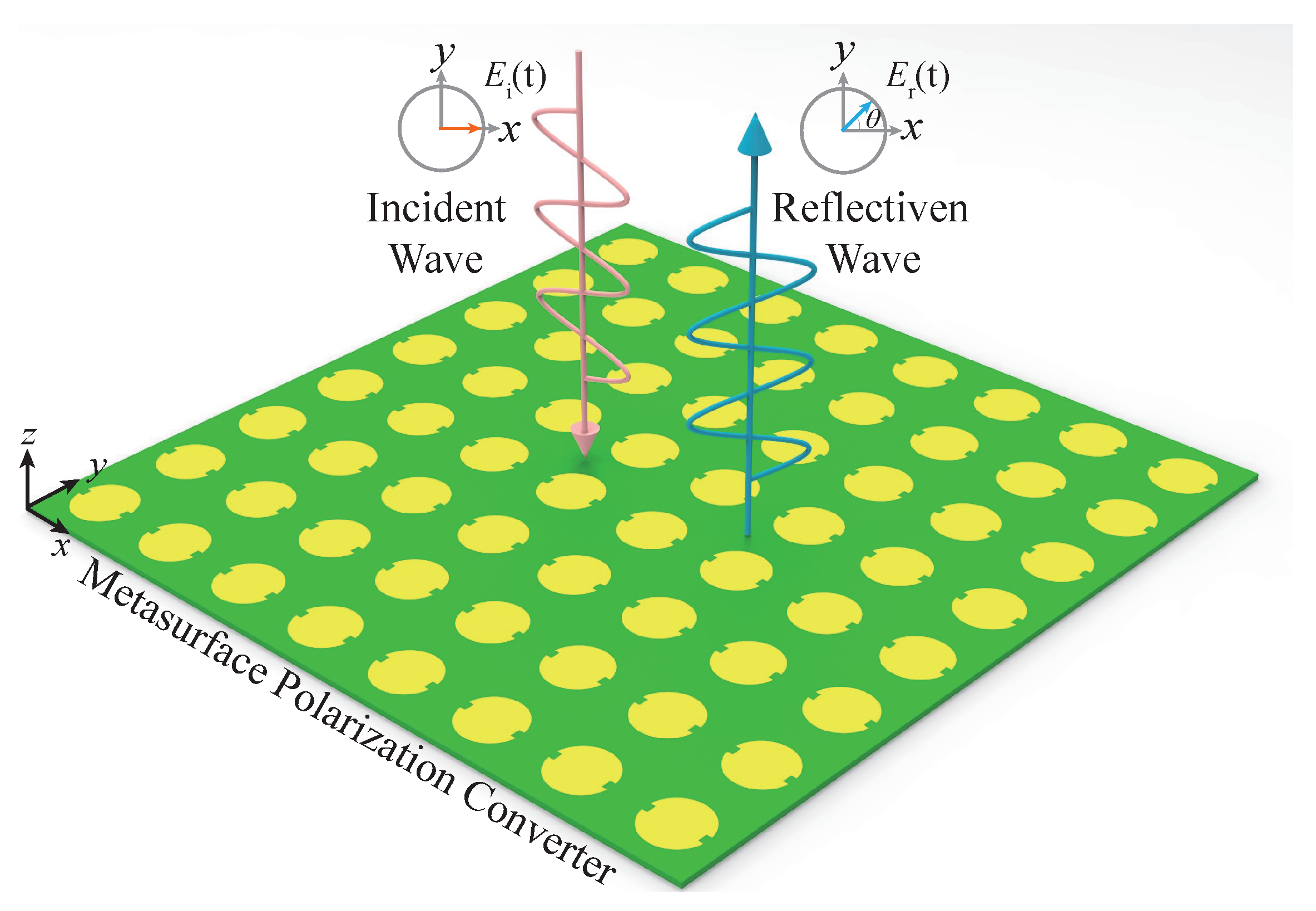
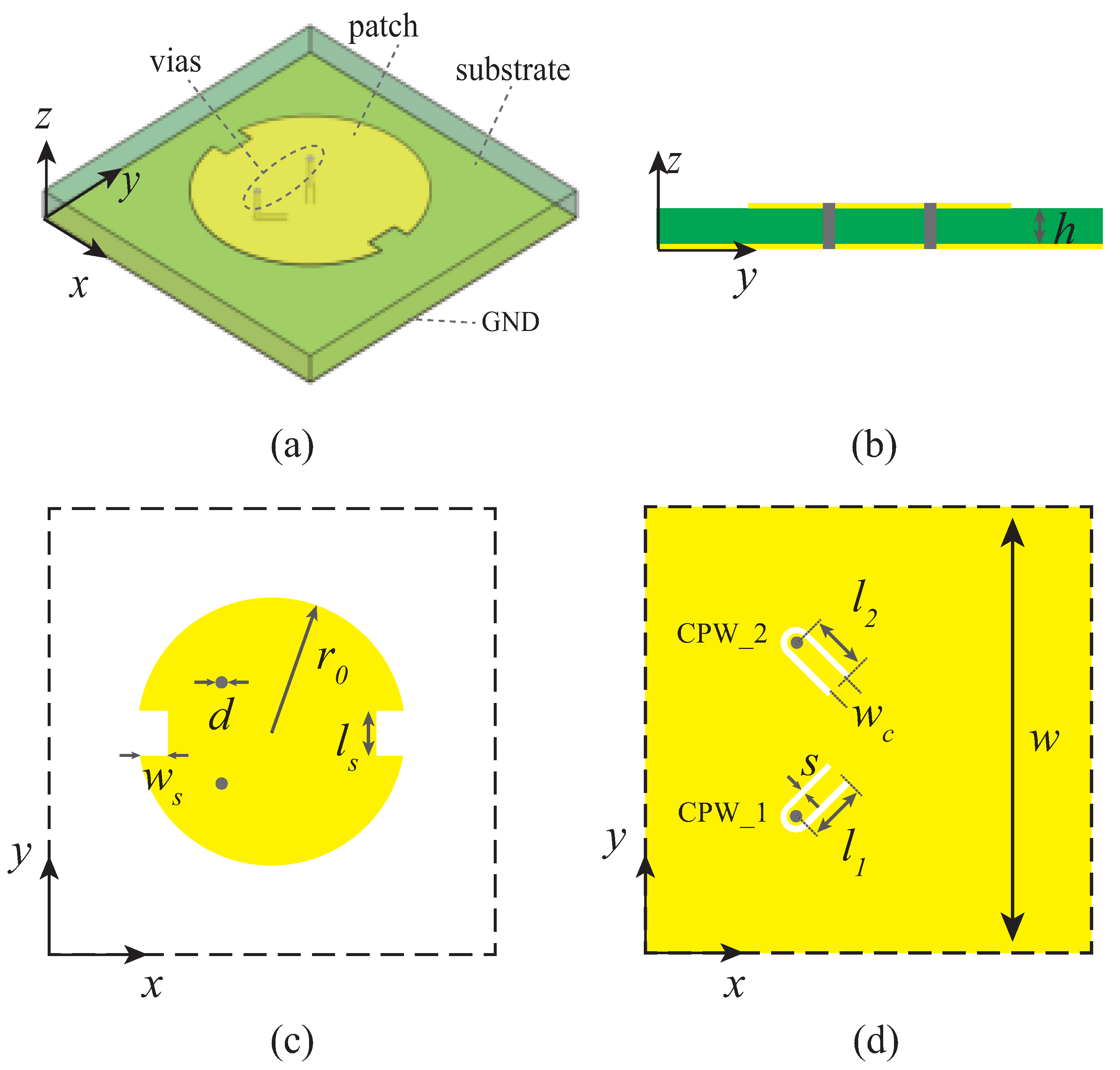
2. General Concept and Metasurface Unit Cell Design

Figure 1 illustrates the conceptual function of the proposed metasurface polarization converter. The metasurface polarization converter consists of a group of periodic notched circular patches. An x polarized harmonic incident wave, E i ( t ) , impinges on the metasurface-based polarization converter, the incident wave interacts with the metasurface particles and is scattered back as the reflected wave, E r ( t ) , to the free space. The linear polarization of the reflected wave, E r ( t ) , is rotated by an angle of θ , compared with the incident wave, E i ( t ) .
Figure 2 shows the unit cell of the proposed metasurface polarization converter. Figure 2a shows the perspective view of the metasurface unit cell, which consists of a top-layer notched circular patch and a bottom-layer ground that are printed on a Roger 4350 dielectric substrate with the dielectric constant 3.66 and the loss tangent is 0.004. The top layer and bottom layer are connected through two metallized vias, as shown in the side view of Figure 2b. Figure 2c shows the top-layer structure, a notched circular patch with two symmetric notches on its two sides.
There are two vias that are located on the left part of the patch which are connected to the bottom layer of the unit cell and can pick up the two circularly polarized components, respectively. Figure 2d shows the bottom layer of the unit cell. Two coplanar waveguide (CPW) transmission lines with different length, l 1 and l 2 , are connected with the top layer through the two metallized vias to adjust the reflecting phase of the two circularly polarized components. The bottom layer has two functions. Firstly, it is used as the ground plane to reflect the incident wave. Meanwhile, it is also applied as the ground for the two CPW transmission lines. The overall design parameters of the unit cell are listed in Table 1.

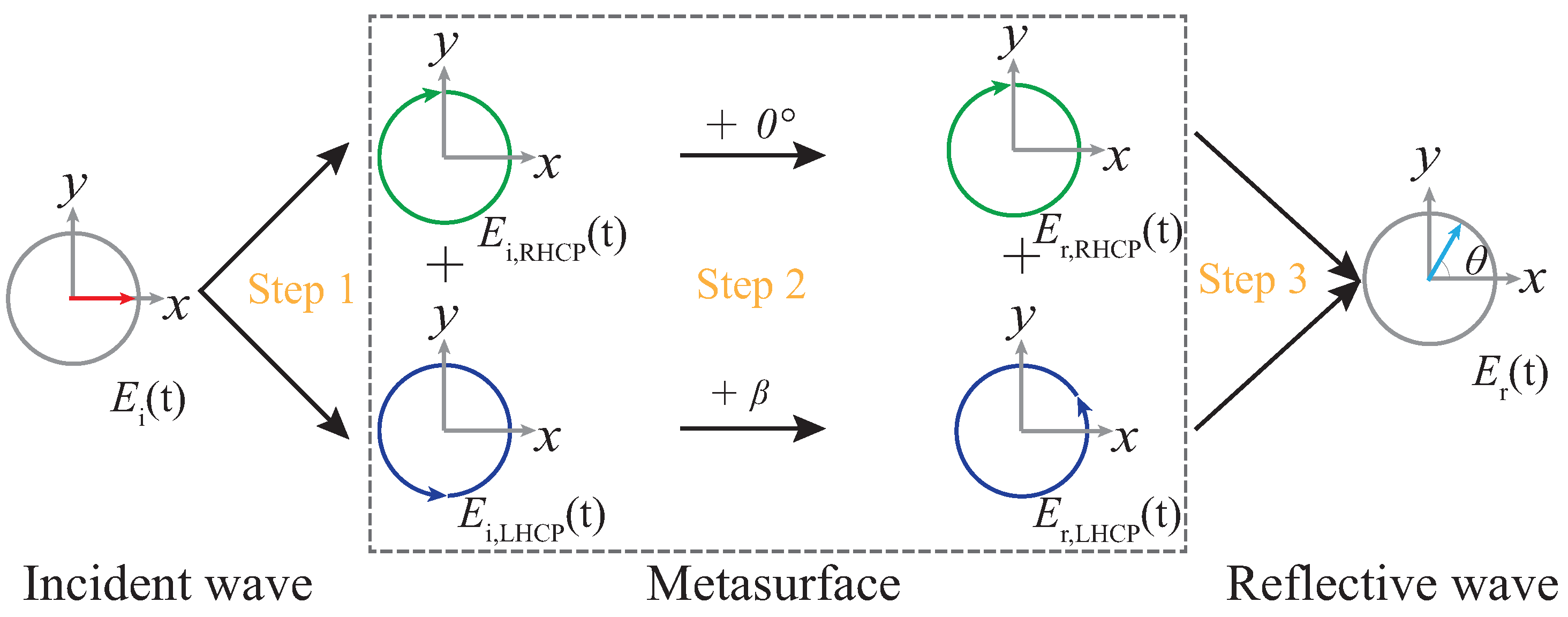
3. Operating Principle Based on Linear-to-Circular Polarization Decomposition and Recombination

Figure 3 illustrates the basic principle of the proposed metasurface polarization converter based on the concept of linear-to-circular polarization decomposition and recombination. It can be divided into three steps.
The first step is to separate the linearly polarized incident wave E i ( t ) into two orthogonal left-hand circularly polarized (LHCP) and right-hand circularly polarized (RHCP) waves. It is well known that any linearly polarized wave may be divided into two orthogonal circularly polarized wave. For instance,
E i ( t ) = e j ω 0 t x = 1 2 ( e j ω 0 t x + e j ( ω 0 t + π / 2 ) y ) + 1 2 ( e j ω 0 t x e j ( ω 0 t + π / 2 ) y ) ,
where ω 0 is the angular frequency of the incident wave. The first term in the last equivalent represents the RHCP component and the second term in the last equivalent represents the LHCP component, which are
E i , RHCP ( t ) = 1 2 ( e j ω 0 t x + e j ( ω 0 t + π / 2 ) y ) , E i , LHCP ( t ) = 1 2 ( e j ω 0 t x e j ( ω 0 t + π / 2 ) y ) ,
respectively. In our design, this is realized by the top-layer notched circular patch in the unit cell of Figure 2c. By introducing the notch perturbations on the patch, degenerate modes can be realized. As a result, the LHCP and RHCP components of the incident wave can be picked up by the two vias and sent to the bottom-layer CPW transmission lines. This process can be understood with the help of cavity model. If there are no two notches, the regular circular patch can be regarded as a lossy resonator, where the top-layer patch and the ground are electric walls, and the space around the circular patch is magnetic wall. This circular patch antenna usually works in the main mode. When two notches are loaded, the current path on the surface of the patch is subject to geometric perturbation, so that the main mode is separated into two adjacent modes. By selecting the appropriate notch size, the two modes can be orthogonal to each other, with equal amplitude and 90 phase difference, thus forming circular polarization [44,45]. In order to demonstrate the linear-to-circular polarization decomposition or recombination function of the proposed unit cell, the two via locations on the top-layer patch are used as the feeding ports of the patch to perform full-wave simulation, respectively. Figure 4 plots the current distribution on the top-layer patch, where in Figure 4a, port 1 is selected as the feeding point, and in Figure 4b, port 2 is selected as the feeding point. It clears shows that in Figure 4a, the current rotates counterclockwise, while in Figure 4b, the current rotates clockwise, which demonstrates that port 1 and port 2 will pick up the LHCP and RHCP components of the incident wave, respectively.
The second step is to add different phase delays to the two circularly polarized components. For instance, if 0 and β are added to the RHCP and LHCP components, the two components in the reflective wave becomes
E r , RHCP ( t ) = 1 2 ( e j ( ω 0 t + 0 ) x + e j ( ω 0 t + π / 2 + 0 ) y ) , E i , LHCP ( t ) = 1 2 ( e j ( ω 0 t + β ) x e j ( ω 0 t + π / 2 + β ) y ) ,
respectively. In our design, this is realized by the bottom-layer CPW transmission lines in the unit cell of Figure 2d. By changing the length of the two CPW transmission lines, different phases are given to the two circularly polarized components.
The final step is the combination of these two reflected orthogonal circularly polarized components, which is
E r ( t ) = E r , RHCP ( t ) + E i , LHCP ( t ) = 1 2 e j ω 0 t ( 1 + e j β ) x + 1 2 e j ( ω 0 t + π / 2 ) ( 1 e j β ) y = 1 2 e j ω 0 t [ ( 1 + e j β ) x j ( 1 e j β ) y ] = 1 2 e j ω 0 t [ ( e j 2 π + e j β ) x j ( ( e j 2 π e j β ) y ] = 1 2 e j ω 0 t e j ( 2 π β ) / 2 [ e j ( 2 π + β ) / 2 + e j ( 2 π + β ) / 2 ] x j [ e j ( 2 π + β ) / 2 e j ( 2 π + β ) / 2 ] y = e j ω 0 t e j ( 2 π β ) / 2 cos [ ( 2 π + β ) / 2 ] x + sin [ ( 2 π + β ) / 2 ] y = e j ω 0 t e j ( 2 π β ) / 2 [ cos ( β / 2 ) x + sin ( β / 2 ) y ] .
Equation (4) shows that the reflected wave, E r ( t ) is a linearly polarized wave with the polarization direction
θ = arctan E r , y ( t ) E r , x ( t ) = β 2 .
Similarly, if 0 and β are added to the LHCP and RHCP components, the reflected wave, E r ( t ) , becomes
E r ( t ) = E r , RHCP ( t ) + E i , LHCP ( t ) = 1 2 e j ω 0 t ( e j β + 1 ) x + 1 2 e j ( ω 0 t + π / 2 ) ( e j β 1 ) y = 1 2 e j ω 0 t [ ( e j β + 1 ) x j ( e j β 1 ) y ] = 1 2 e j ω 0 t [ ( e j β + e j 2 π ) x j ( ( e j β e j 2 π ) y ] = 1 2 e j ω 0 t e j ( β + 2 π ) / 2 [ e j ( β 2 π ) / 2 + e j ( β 2 π ) / 2 ] x j [ e j ( β 2 π ) / 2 e j ( β 2 π ) / 2 ] y = e j ω 0 t e j ( β 2 π ) / 2 cos [ ( β 2 π ) / 2 ] x + sin [ ( β 2 π ) / 2 ] y = e j ω 0 t e j ( 2 π β ) / 2 [ cos ( β / 2 ) x + sin ( β / 2 ) y ] ,
whose polarization direction is
θ = arctan E r , y ( t ) E r , x ( t ) = β 2 .
Equations (5) and (7) show that the rotated polarization angle θ of the reflective wave is exactly half of the added phase difference between the two circularly polarized components, β . The polarization rotating direction can be adjusted by switching the components in which β is added. In our design, the two orthogonal circularly polarized components picked up by the top-layer patch are reflected by their corresponding CPW transmission lines to the top-layer patch and recombine as the polarization-rotated reflective wave in the free space.

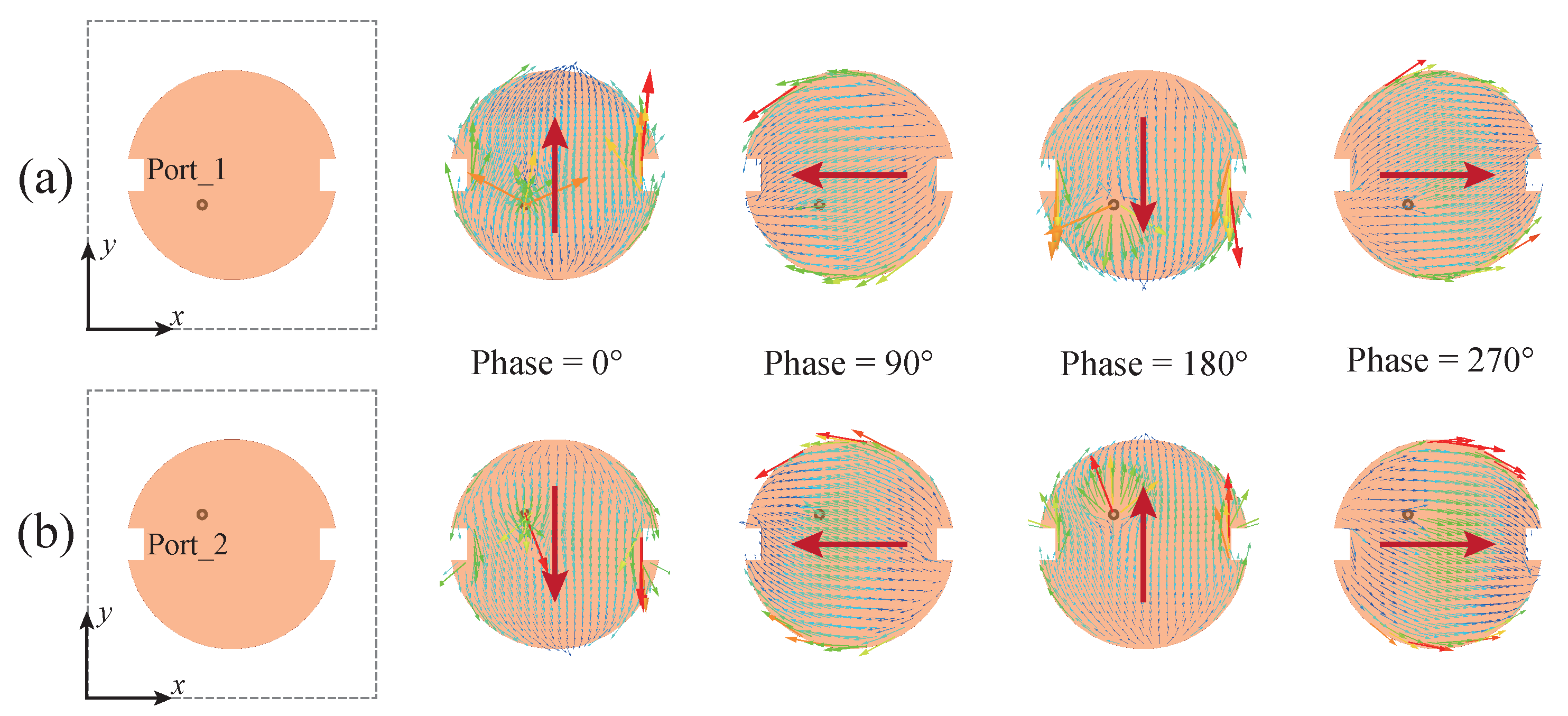
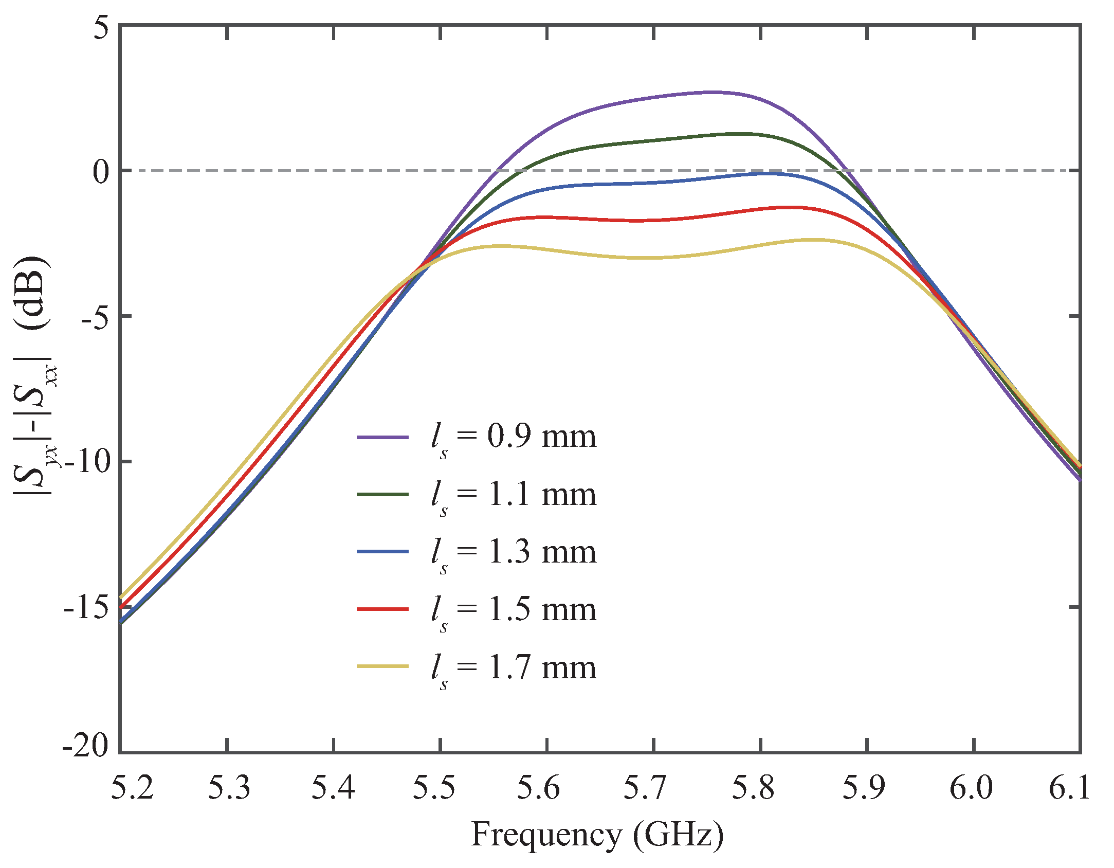
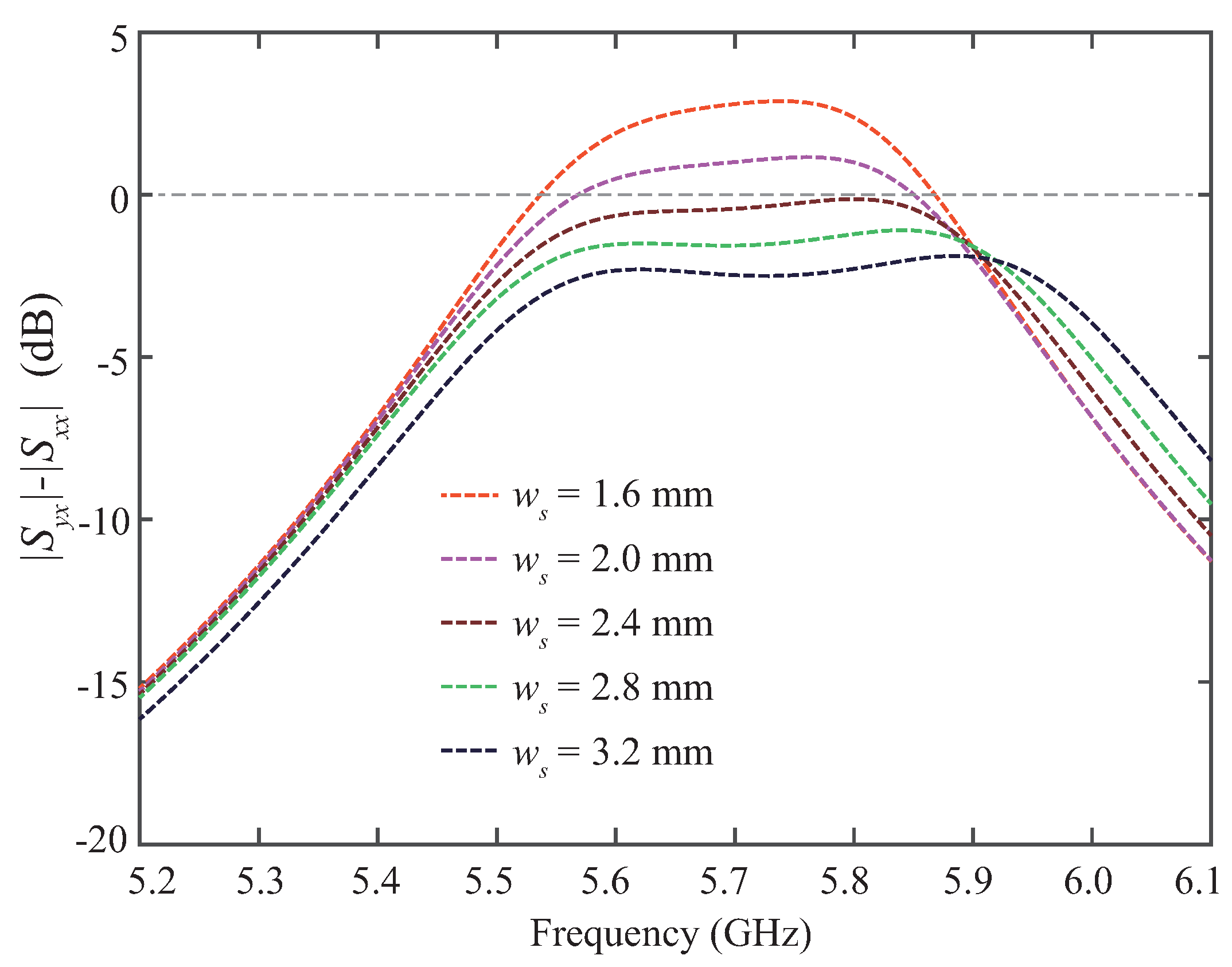
4. Full-Wave Simulation and Analysis

The proposed metasurface unit cell is full-wave simulated to demonstrate the proposed unit cell. Figure 5 plots the magnitudes of the reflection coefficients for different l 1 , when l 2 is fixed to 0. It shows that when l 1 = 0 , which is corresponding to the case β = 0 , there is almost no polarization conversion. As the length of l 1 increases, the co-polarization reflection coefficient | S x x | decreases, while the cross-polarization reflection coefficient | S y x | increases. When l 1 = 2.6 mm, | S x x | = | S y x | , which is the case of 45 polarization conversion.
Figure 6 plots the phases of the reflection coefficients for the two cases, l 1 = 0 , l 2 = 2.6 mm (case 1), and l 1 = 2.6 mm, l 2 = 0 (case 2). In both cases, it is a 45 polarization converter, as shown in Figure 5. However, the co-polarization and cross-polarization reflection coefficients are in phase for case 1 and out of phase for case 2, which demonstrates that in case 1, the polarization is counterclockwise rotated, while in case 2, the polarization is clockwise rotated.
Figure 7 plots the simulated magnitude difference between co-polarization and cross-polarization reflected wave under x-polarized incident wave with different oblique incident angle α , for the case l 1 = 2.6 mm, l 2 = 0 , which is corresponding to 45 polarization converter. It shows that the 45 metasurface polarization converter has a stable performance under a wide oblique incidence up to 50 , with the performance, | | S y x | S | x x | | < 3 dB, from 5.44 GHz to 5.87 GHz.
Figure 8 plots the full-wave simulated electric field distribution of the designed 45 metasurface under x polarized normal incident wave at 5.7 GHz at the plane z = 10 mm. This result shows that the direction of the reflective electric field becomes 45 , which demonstrates the 45 polarization conversion performance.
Figure 9 and Figure 10 study the 45 metasurface polarization converting performance with different notching sizes, l s and w s , under normal x polarized incident wave, respectively. They show that the polarization converting performance is very sensitive to the size of the notches. This is due to the fact that only notches with appropriate size can introduce the perturbations for degenerate modes to separate the two circularly polarized components of the incident wave. In our design, we choose w s = 2.4 mm and l s = 1.3 mm.

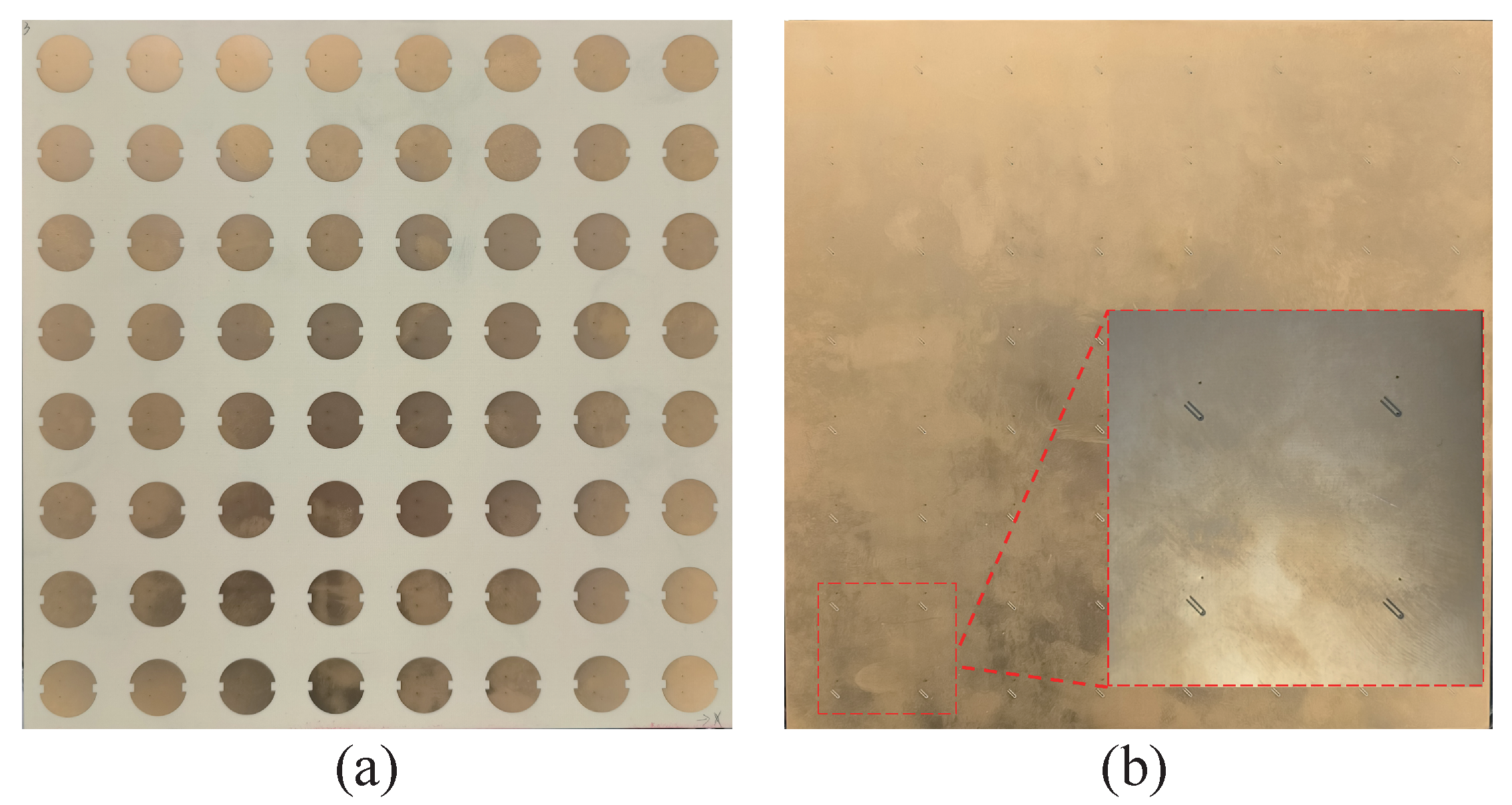
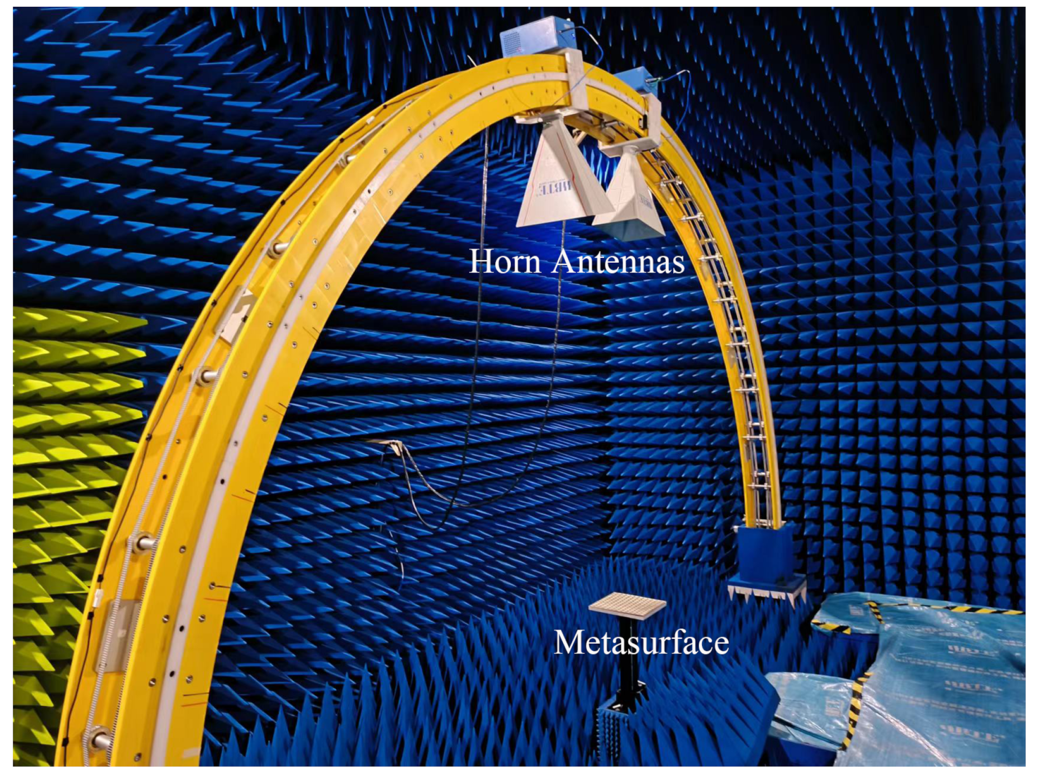
5. Experimental Demonstration

Finally, a 45 metasurface polarization converter with 8 × 8 proposed unit cell is designed, fabricated, and experimentally demonstrated, in which the length of the two CPW transmission lines l 1 and l 2 are set as l 1 = 2.6 mm and l 2 = 0 . Figure 11 provides the photos of the fabricated metasurface prototypes, where Figure 11a,b show the top view and bottom view of the metasurface prototype, respectively. Figure 12 shows the experimental setup. The overall setup is surrounded by absorbing materials to avoid undesired scattering. A pair of horn antennas are placed on an arc track, which work as the transmitting and receiving antennas, respectively, and are connected to a vector network analyzer (VNA). The metasurface to be tested are placed at the center of the arc track.
Figure 13 plots the measured results of the magnitude difference between cross-polarization and co-polarization under x polarized incident waves with different oblique angle α . The measured results agree well the simulation results in Figure 7, showing that the designed metasurface polarization converter reflects balanced x and y polarized components in a wide band for 45 polarization conversion. Finally, Figure 14 plots the 45 polarization conversion ratio (PCR) under x polarized incident wave with different oblique angle α , based on the measured results using the equation
P C R ( θ ) = | S y x sin θ + S x x cos θ | 2 | S y x | 2 + | S x x | 2 ,
where θ = 45 . It shows that the designed metasurface polarization converter can achieve a high conversion ratio larger than 85 % from 5.38 GHz to 5.78 GHz under a wide oblique incident wave up to 50 . As the oblique incident angle α increases to larger than 50 , the decreasing of the PCR in the operating band becomes innegligible, which is due to the fact that as the incident angle increases, the resonate frequency of the top-layer patch shifts, resulting in less energy is captured by the metasurface and less PCR.
Finally, Table 2 compares the polarization conversion performance between this work and other reported works. The comparison shows that the proposed metasurface polarization converter exhibits the unique features of arbitrary linear rotating angle and stable high PCR under a wide oblique incident angle up to 50 .

6. Conclusions

A novel linear polarization metasurface converter with the features of arbitrary polarization rotation angle and stable response under wide oblique incidence is presented in this paper. The proposed metasurface polarization converter is guided by the concept of linear-to-circular polarization decomposition and recombination and is realized based on a notched circular patch unit cell, whose polarization rotating phase is tunable by altering the length of the CPW transmission lines connected to the notched circular patch. The metasurface polarization converter is theoretically analyzed and demonstrated by both full-wave simulation and experiment, which shows that the proposed metasurface polarization can realize more than 85 % polarization conversion efficiency at an oblique incident angle of up to 50 . The proposed arbitrary polarization metasurface converter may provide a new solution to flexible polarization manipulation metasurface design.

Author Contributions

Conceptualization, T.Z. and X.W.; validation, H.W. and T.Z.; formal analysis, T.Z. and X.W.; investigation, T.Z. and H.W.; data curation, H.W. and X.W.; writing—original draft preparation, T.Z.; writing—review and editing, X.W., H.W., Z.C. and C.P.; supervision, Z.C.; project administration, C.P.; funding acquisition, Z.C. All authors have read and agreed to the published version of the manuscript.

Funding

This research was funded by National Key R&D Program of China, grant number 2019YFE0125800.

Institutional Review Board Statement

Not applicable.

Data Availability Statement

Not applicable.

Conflicts of Interest

The authors declare no conflict of interest.

References

  1. Balanis, C.A. Antenna Theory: Analysis and Design; John Wiley & Sons: Hoboken, NJ, USA, 2015. [Google Scholar]
  2. Zhao, Y.; Cao, X.; Gao, J.; Yao, X.; Liu, T.; Li, W.; Li, S. Broadband low-RCS metasurface and its application on antenna. IEEE Trans. Antennas Propag. 2016, 64, 2954–2962. [Google Scholar] [CrossRef]
  3. Jia, Y.; Liu, Y.; Guo, Y.J.; Li, K.; Gong, S. A dual-patch polarization rotation reflective surface and its application to ultra-wideband RCS reduction. IEEE Trans. Antennas Propag. 2017, 65, 3291–3295. [Google Scholar] [CrossRef] [Green Version]
  4. Han, J.; Cao, X.; Gao, J.; Wei, J.; Zhao, Y.; Li, S.; Zhang, Z. Broadband radar cross section reduction using dual-circular polarization diffusion metasurface. IIEEE Antennas Wirel. Propag. Lett. 2018, 17, 969–973. [Google Scholar] [CrossRef]
  5. Akbari, M.; Samadi, F.; Sebak, A.R.; Denidni, T.A. Superbroadband diffuse wave scattering based on coding metasurfaces: Polarization conversion metasurfaces. IEEE Antennas Propag. Mag. 2019, 61, 40–52. [Google Scholar] [CrossRef]
  6. Zhou, H.; Sain, B.; Wang, Y.; Schlickriede, C.; Zhao, R.; Zhang, X.; Wei, Q.; Li, X.; Huang, L.; Zentgraf, T. Polarization-encrypted orbital angular momentum multiplexed metasurface holography. ACS Nano 2020, 14, 5553–5559. [Google Scholar] [CrossRef]
  7. Wang, X.; Yang, G.M. Time-coding spread-spectrum reconfigurable intelligent surface for secure wireless communication: Theory and experiment. Opt. Express 2021, 29, 32031–32041. [Google Scholar] [CrossRef]
  8. Wang, X.; Caloz, C. Phaser-based polarization-dispersive antenna and application to encrypted communication. In Proceedings of the IEEE International Symposium on Antennas and Propagation, San Diego, CA, USA, 9–14 July 2017; IEEE: Piscataway, NJ, USA, 2017; pp. 2187–2188. [Google Scholar]
  9. Zhang, Q.; Pan, W. Countering method for active jamming based on dual-polarization radar seeker. Int. J. Microw. Wirel. Technol. 2017, 9, 1067–1073. [Google Scholar] [CrossRef] [Green Version]
  10. He, Y.; Zhang, T.; He, H.; Zhang, P.; Yang, J. Polarization Anti-Jamming Interference Analysis With Pulse Accumulation. IEEE Trans. Signal Process. 2022, 70, 4772–4787. [Google Scholar] [CrossRef]
  11. Rajabalipanah, H.; Rouhi, K.; Abdolali, A.; Iqbal, S.; Zhang, L.; Liu, S. Real-time terahertz meta-cryptography using polarization-multiplexed graphene-based computer-generated holograms. Nanophotonics 2020, 9, 2861–2877. [Google Scholar] [CrossRef]
  12. Fan, S.; Cao, C.; Zeng, X.; Ning, J.; Yan, X.; Wang, R.; Wang, X.; Song, Q.; Chen, K.; Liu, Y.; et al. A RoF system based on polarization multiplexing and carrier suppression to generate frequency eightfold millimeter-wave. Results Phys. 2019, 12, 1450–1454. [Google Scholar] [CrossRef]
  13. Zhuang, Z.; Suh, S.W.; Patel, J. Polarization controller using nematic liquid crystals. Opt. Lett. 1999, 24, 694–696. [Google Scholar] [CrossRef] [PubMed]
  14. Ikeda, T.; Sasaki, T.; Ichimura, K. Photochemical switching of polarization in ferroelectric liquid-crystal films. Nature 1993, 361, 428–430. [Google Scholar] [CrossRef]
  15. Fu, H.; Cohen, R.E. Polarization rotation mechanism for ultrahigh electromechanical response in single-crystal piezoelectrics. Nature 2000, 403, 281–283. [Google Scholar] [CrossRef] [PubMed]
  16. Caloz, C.; Achouri, K. Electromagnetic Metasurfaces: Theory and Applications; John Wiley & Sons: Hoboken, NJ, USA, 2021. [Google Scholar]
  17. Holsteen, A.L.; Cihan, A.F.; Brongersma, M.L. Temporal color mixing and dynamic beam shaping with silicon metasurfaces. Science 2019, 365, 257–260. [Google Scholar] [CrossRef]
  18. Keren-Zur, S.; Avayu, O.; Michaeli, L.; Ellenbogen, T. Nonlinear beam shaping with plasmonic metasurfaces. ACS Photonics 2016, 3, 117–123. [Google Scholar] [CrossRef]
  19. Avayu, O.; Eisenbach, O.; Ditcovski, R.; Ellenbogen, T. Optical metasurfaces for polarization-controlled beam shaping. Opt. Lett. 2014, 39, 3892–3895. [Google Scholar] [CrossRef]
  20. Deng, T.; Liang, J.; Cai, T.; Wang, C.; Wang, X.; Lou, J.; Du, Z.; Wang, D. Ultra-thin and broadband surface wave meta-absorber. Opt. Express 2021, 29, 19193–19201. [Google Scholar] [CrossRef]
  21. Wen, Y.; Ma, W.; Bailey, J.; Matmon, G.; Yu, X.; Aeppli, G. Planar broadband and high absorption metamaterial using single nested resonator at terahertz frequencies. Opt. Lett. 2014, 39, 1589–1592. [Google Scholar] [CrossRef]
  22. Lee, K.; Son, J.; Park, J.; Kang, B.; Jeon, W.; Rotermund, F.; Min, B. Linear frequency conversion via sudden merging of meta-atoms in time-variant metasurfaces. Nat. Photonics 2018, 12, 765–773. [Google Scholar] [CrossRef]
  23. Wu, Z.; Grbic, A. Serrodyne frequency translation using time-modulated metasurfaces. IEEE Trans. Antennas Propag. 2019, 68, 1599–1606. [Google Scholar] [CrossRef]
  24. Chen, Z.N. Metantennas: From Patch Antennas to Metasurface Mosaic Antennas. In Proceedings of the 2020 IEEE Asia-Pacific Microwave Conference (APMC), Hong Kong, China, 8–11 December 2020; IEEE: Hoboken, NJ, USA, 2020; pp. 363–365. [Google Scholar]
  25. Faenzi, M.; Minatti, G.; González-Ovejero, D.; Caminita, F.; Martini, E.; Della Giovampaola, C.; Maci, S. Metasurface antennas: New models, applications and realizations. Sci. Rep. 2019, 9, 10178. [Google Scholar] [CrossRef] [PubMed] [Green Version]
  26. González-Ovejero, D.; Minatti, G.; Chattopadhyay, G.; Maci, S. Multibeam by metasurface antennas. IEEE Trans. Antennas Propag. 2017, 65, 2923–2930. [Google Scholar] [CrossRef]
  27. Liu, S.; Yang, D.; Chen, Y.; Sun, K.; Zhang, X.; Xiang, Y. Low-profile broadband metasurface antenna under multimode resonance. IEEE Antennas Wirel. Propag. Lett. 2021, 20, 1696–1700. [Google Scholar] [CrossRef]
  28. Wang, X.; Caloz, C. Spread-spectrum selective camouflaging based on time-modulated metasurface. IEEE Trans. Antennas Propag. 2020, 69, 286–295. [Google Scholar] [CrossRef]
  29. Wang, X.; Caloz, C. Spread-spectrum camouflaging based on time-modulated metasurface. In Proceedings of the IEEE International Symposium on Antennas and Propagation, Atlanta, GA, USA, 7–12 July 2019; IEEE: Hoboken, NJ, USA, 2019; pp. 1411–1412. [Google Scholar]
  30. Noishiki, T.; Kuse, R.; Fukusako, T. Wideband metasurface polarization converter with double-square-shaped patch elements. Prog. Electromagn. Res. C 2020, 105, 47–58. [Google Scholar] [CrossRef]
  31. Guo, Y.; Xu, J.; Lan, C.; Bi, K. Broadband and high-efficiency linear polarization converter based on reflective metasurface. Eng. Sci. 2021, 14, 39–45. [Google Scholar] [CrossRef]
  32. Wang, X.; Yang, G.M. Linear-polarization metasurface converter with an arbitrary polarization rotating angle. Opt. Express 2021, 29, 30579–30589. [Google Scholar] [CrossRef]
  33. Li, J.; Kong, X.; Wang, J.; Miao, Z.; Wang, X.; Shen, X.; Zhao, L. Dual-band polarization-insensitive orbital angular momentum beam generation based on 1-bit polarization-converting transmitting coding metasurface. Int. J. RF Microw. Comput.-Aided Eng. 2022, 32, e23397. [Google Scholar] [CrossRef]
  34. Khan, M.I.; Fraz, Q.; Tahir, F.A. Ultra-wideband cross polarization conversion metasurface insensitive to incidence angle. J. Appl. Phys. 2017, 121, 045103. [Google Scholar] [CrossRef]
  35. Khan, M.I.; Khalid, Z.; Tahir, F.A. Linear and circular-polarization conversion in X-band using anisotropic metasurface. Sci. Rep. 2019, 9, 4552. [Google Scholar] [CrossRef]
  36. Wang, H.B.; Cheng, Y.J.; Chen, Z.N. Dual-band miniaturized linear-to-circular metasurface polarization converter with wideband and wide-angle axial ratio. IEEE Trans. Antennas Propag. 2021, 69, 9021–9025. [Google Scholar] [CrossRef]
  37. Ratni, B.; de Lustrac, A.; Piau, G.P.; Burokur, S.N. Electronic control of linear-to-circular polarization conversion using a reconfigurable metasurface. Appl. Phys. Lett. 2017, 111, 214101. [Google Scholar] [CrossRef]
  38. Lin, B.; Lv, L.; Guo, J.; Liu, Z.; Ji, X.; Wu, J. An ultra-wideband reflective linear-to-circular polarization converter based on anisotropic metasurface. IEEE Access 2020, 8, 82732–82740. [Google Scholar] [CrossRef]
  39. Akgol, O.; Altintas, O.; Unal, E.; Karaaslan, M.; Karadag, F. Linear to left-and right-hand circular polarization conversion by using a metasurface structure. Int. J. Microw. Wirel. Technol. 2018, 10, 133–138. [Google Scholar] [CrossRef]
  40. Liu, X.; Zhang, J.; Li, W.; Lu, R.; Li, L.; Xu, Z.; Zhang, A. Three-band polarization converter based on reflective metasurface. IEEE Antennas Wirel. Propag. Lett. 2016, 16, 924–927. [Google Scholar] [CrossRef]
  41. Akgol, O.; Unal, E.; Altintas, O.; Karaaslan, M.; Karadag, F.; Sabah, C. Design of metasurface polarization converter from linearly polarized signal to circularly polarized signal. Optik 2018, 161, 12–19. [Google Scholar] [CrossRef]
  42. Arbabi, A.; Horie, Y.; Bagheri, M.; Faraon, A. Dielectric metasurfaces for complete control of phase and polarization with subwavelength spatial resolution and high transmission. Nat. Nanotechnol. 2015, 10, 937–943. [Google Scholar] [CrossRef] [Green Version]
  43. Lin, B.Q.; Guo, J.X.; Chu, P.; Huo, W.J.; Xing, Z.; Huang, B.G.; Wu, L. Multiple-band linear-polarization conversion and circular polarization in reflection mode using a symmetric anisotropic metasurface. Phys. Rev. Appl. 2018, 9, 024038. [Google Scholar] [CrossRef]
  44. James, J.R.; Hall, P.S. Handbook of Microstrip Antennas; The Institution of Engineering and Technology: London, UK, 1989. [Google Scholar]
  45. Sharma, P.; Gupta, K. Analysis and optimized design of single feed circularly polarized microstrip antennas. IEEE Trans. Antennas Propag. 1983, 31, 949–955. [Google Scholar] [CrossRef] [Green Version]
  46. Zhang, L.; Zhou, P.; Lu, H.; Chen, H.; Xie, J.; Deng, L. Ultra-thin reflective metamaterial polarization rotator based on multiple plasmon resonances. IEEE Antennas Wirel. Propag. Lett. 2015, 14, 1157–1160. [Google Scholar] [CrossRef]
  47. Xu, J.; Li, R.; Qin, J.; Wang, S.; Han, T. Ultra-broadband wide-angle linear polarization converter based on H-shaped metasurface. Opt. Express 2018, 26, 20913–20919. [Google Scholar] [CrossRef] [PubMed]
  48. Bhattacharyya, S.; Ghosh, S.; Srivastava, K.V. A wideband cross polarization conversion using metasurface. Radio Sci. 2017, 52, 1395–1404. [Google Scholar] [CrossRef] [Green Version]
  49. Fu, C.; Sun, Z.; Han, L.; Liu, C. Dual-bandwidth linear polarization converter based on anisotropic metasurface. IEEE Photonics J. 2020, 12, 4600511. [Google Scholar] [CrossRef]
  50. Sun, H.; Gu, C.; Chen, X.; Li, Z.; Liu, L.; Martín, F. Ultra-wideband and broad-angle linear polarization conversion metasurface. J. Appl. Phys. 2017, 121, 174902. [Google Scholar] [CrossRef]
Figure 1. Functional schematic diagram of the proposed metasurface-based linear polarization converter. The polarization of the reflected electromagnetic wave rotates by an angle θ compared with the incident wave.
Crystals 12 01646 g001
Figure 2. Unit cell of the proposed linear polarization metasurface converter. (a) Perspective view. (b) Side view. (c) Top layer. (d) Bottom layer.
Crystals 12 01646 g002
Figure 3. Operating principle of the proposed metasurface polarization converter.
Crystals 12 01646 g003
Figure 4. Full-wave simulated surface current distribution of the notched circular patch under different feeding ports. (a) Fed by port 1. (b) Fed by port 2.
Crystals 12 01646 g004
Figure 5. Magnitudes of reflection coefficients for different l 1 , when l 2 = 0 .
Crystals 12 01646 g005
Figure 6. Phases of reflection coefficients for l 1 = 0 mm, l 2 = 2.6 mm (case 1) and l 1 = 2.6 mm, l 2 = 0 mm (case 2).
Crystals 12 01646 g006
Figure 7. Simulated magnitude difference between co-polarization and cross-polarization reflected wave under x-polarized incident wave with different oblique incident angle α , for the case l 1 = 2.6 mm, l 2 = 0 , corresponding to a 45 polarization converter.
Crystals 12 01646 g007
Figure 8. The full-wave simulated electric field distribution of the designed 45 metasurface under x polarized normal incident wave at 5.7 GHz at the plane z = 10 mm. The blue arrow represents the average direction of the electric field.
Crystals 12 01646 g008
Figure 9. Simulated magnitude difference between co-polarization and cross-polarization reflected wave for different l s , under normal x polarized incident wave.
Crystals 12 01646 g009
Figure 10. Simulated magnitude difference between co-polarization and cross-polarization reflected wave for different w s , under normal x -polarized incident wave.
Crystals 12 01646 g010
Figure 11. Photos of the fabricated metasurface prototype. (a) Top view. (b) Bottom view.
Crystals 12 01646 g011
Figure 12. Photo of the experimental setup.
Crystals 12 01646 g012
Figure 13. Measured magnitude difference between cross-polarization and co-polarization under x polarized incident waves with different oblique angle α .
Crystals 12 01646 g013
Figure 14. Measured 45 polarization conversion ratio (PCR) under x polarized incident wave with different oblique angle α , obtained by Equation (8).
Crystals 12 01646 g014
Table 1. Design parameters of the proposed metasurface unit cell.
Parameterwhr 0 dw s l s w c s
Value (mm)25.001.5248.000.352.401.300.400.22
Table 2. Comparison between reported work and this work.
WorkPolarization Rotating AngleOblique Incident AnglePCR
Ref. [46]90.000– 30 68.6 %
Ref. [47]90.000– 41 . 5 80.0 %
Ref. [48]90.000- 45 80.0 %
Ref. [49]90.000– 45 95.0 %
Ref. [50]90.000– 50 90.0 %
This workArbitary0– 50 85.0 %
Publisher’s Note: MDPI stays neutral with regard to jurisdictional claims in published maps and institutional affiliations.

