
Microstructure Evolution and Thermoelectric Property of Pt-PtRh Thin Film Thermocouples


State Key Laboratory of Electronic Thin Films and Integrated Devices, University of Electronic Science and Technology of China, Chengdu 610054, China
*
Authors to whom correspondence should be addressed.
Crystals 2017, 7(4), 96; https://0-doi-org.brum.beds.ac.uk/10.3390/cryst7040096
Submission received: 1 March 2017
/
Revised: 23 March 2017
/
Accepted: 24 March 2017
/
Published: 25 March 2017
Abstract
:Due to their small size, extremely fast response, and low cost, refractory metallic thin film thermocouples (TFTCs) are well suited for the surface temperature measurement of hot components. In this study, PtRh films with different amounts of Rhodium (10% and 13%) were deposited with direct current magnetron sputtering and annealed at different temperatures in air. The chemistry, microstructure, and resistivity of the films were investigated. Type S (Pt10%Rh-Pt) and type R (Pt13%Rh-Pt) TFTC were fabricated on alumina substrates. Rhodium segregation at the surface of PtRh film was observed, and the variation of the thermoelectric properties of TFTCs was discussed based on the chemistry and microstructure of PtRh films.
1. Introduction
Precise measurement of the surface temperature of hot-section components is crucial for efficiency improvement and safety concerns of whole vehicles. In sharp contrast to traditional thermocouple wires, thin film thermocouples (TFTCs) can be directly deposited onto the measured components with a thickness of less than 30 μm. Due to their negligible mass and volume, TFTCs can provide much faster response with minimal disturbance of the gas flow over the surface and almost no impact on the physical characteristics of the measured components [1,2,3,4,5,6,7,8,9]. Metallic-based wire thermocouples such as Pt-PtRh or NiCr-NiSi have been widely applied for decades. However, when deposited in thin film form, the stability and linearity of TFTC is subject to different degrees of degradation—especially in the high temperature range and in highly oxidizing environments [8,10]. Different approaches have been taken to optimize the stability and thermoelectric performance of such metallic TFTCs [4,10,11]. It has been reported that vacuum annealing could increase the sensitivity and stability of Pt-PtRh TFTC, but the mechanism is still unclear.
In the present work, Pt-10%Rh and Pt-13%Rh films—corresponding to positive thermal element of standard type S and type R thermocouples, respectively—were prepared by direct current magnetron sputtering. The films were post annealed in air at different temperatures. The microstructure and resistivity of the films were investigated. Afterwards, Pt and PtRh films were deposited on alumina substrate to form type S and type R TFTC, and the thermoelectric properties of these TFTCs were characterized and discussed.
2. Experiments
2.1. Thin Film Fabrication and Characterization
Pt-Rh thin films were deposited on alumina ceramic substrates by d.c. magnetron sputtering at 400 °C. High purity (99.997 wt. %) 100 mm diameter Pt-10%Rh and Pt-13%Rh disks were used as the target. The distance between target and substrate was 110 mm. The base pressure of the chamber was kept at 8 × 10⁻⁴ Pa, and Argon gas was used as the sputtering media with the total pressure of 0.4 Pa. The sputtering power was 120 W. Before deposition, the target was pre-sputtered for 10 min to remove the surface contamination and absorbed water. The films were deposited for 30 min, and the thickness of the films was approximately 1 μm. All of the films were then annealed in air at different temperatures for 1 h followed by furnace cooling to room temperature.
The microstructure of the films was characterized by X-ray diffraction (XRD, Bede). X-ray photoelectron spectroscopy (XPS) was recorded with a Thermo Scientific K-Alpha spectrometer. The morphology of the films was disclosed by Scanning Electron Microscopy (SEM, INSPECT-F). The resistivity of the films was determined by measuring the sheet resistance by four-point probe (1 mm probe distance) method, and the thickness of the films was detected by Veeco profiler.
2.2. TFTC Fabrication and Calibration
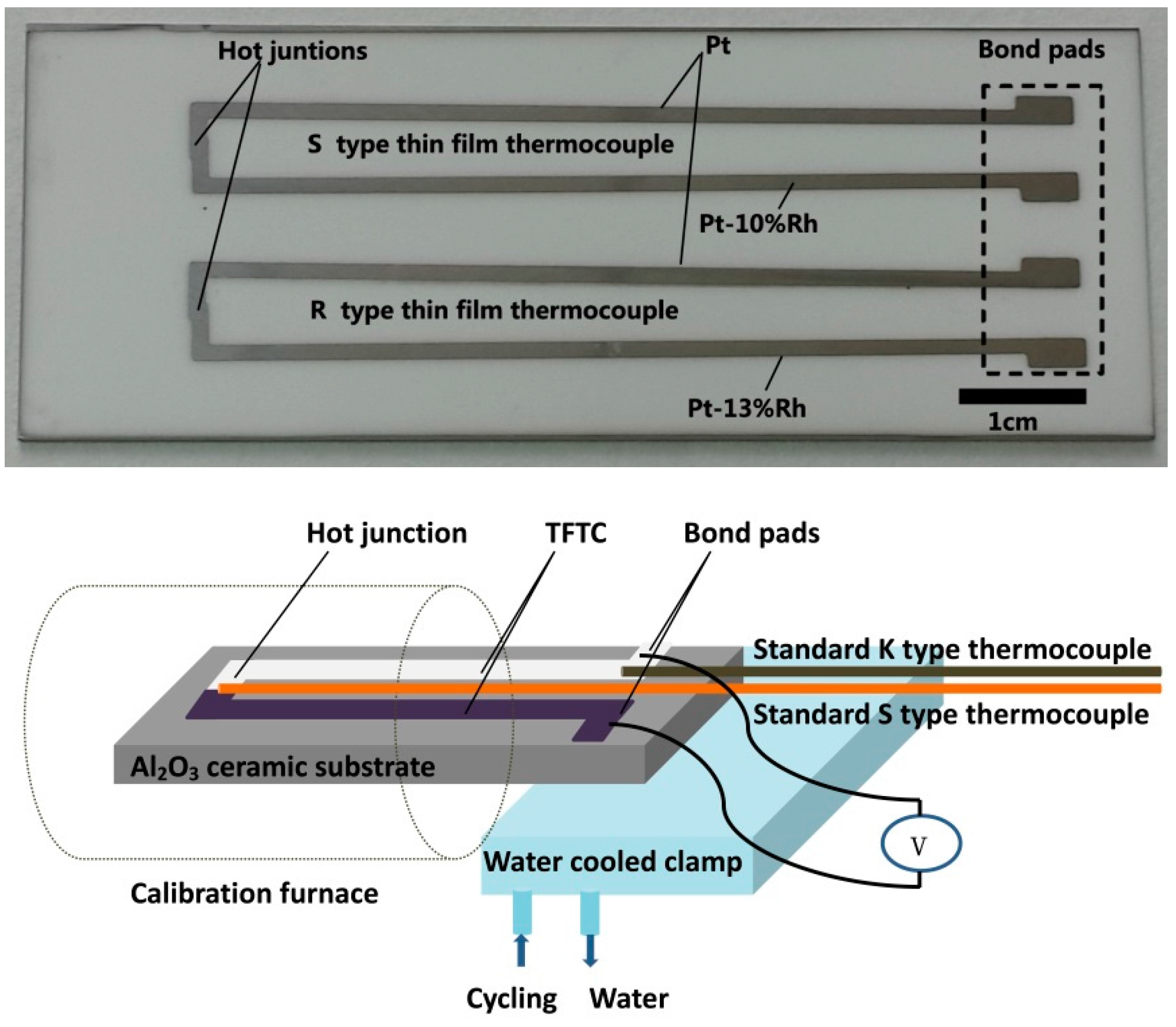
Pt and PtRh thin films were deposited on alumina substrate and patterned with stenciled shadow masks to form type S and type R TFTCs, as shown in Figure 1. The length and width of each thermal element leg were 64 mm and 1 mm, respectively. The size of the junction was about 1 mm × 2 mm.
The TFTCs were statically calibrated with the temperature of hot junction up to 1000 °C. During the calibration, the hot junction of the TFTC was placed in the hot zone of the calibration furnace, and a temperature gradient was applied along the length of the TFTC. A water-cooled clamp was used to chill the bond pad of the TFTC, and the temperature of hot junction and bond pad of TFTC was characterized with standard type-S and type-K wire thermocouples mounted on the back of the substrate, respectively. The bond pad of TFTC was chilled with water-cooled clamp. The platinum wires were fixed at the bond pad by high temperature sliver paste to acquire the thermoelectric output of the TFTCs. A photograph of TFTCs and a schematic of the calibration setup are shown in Figure 1. The TFTCs were calibrated for multiple thermal cycles, and each calibration temperature was held for at least 1 h to reach thermal equilibrium.
3. Results and Discussion
3.1. Microstructure and Resistivity of Pt-Rh Films
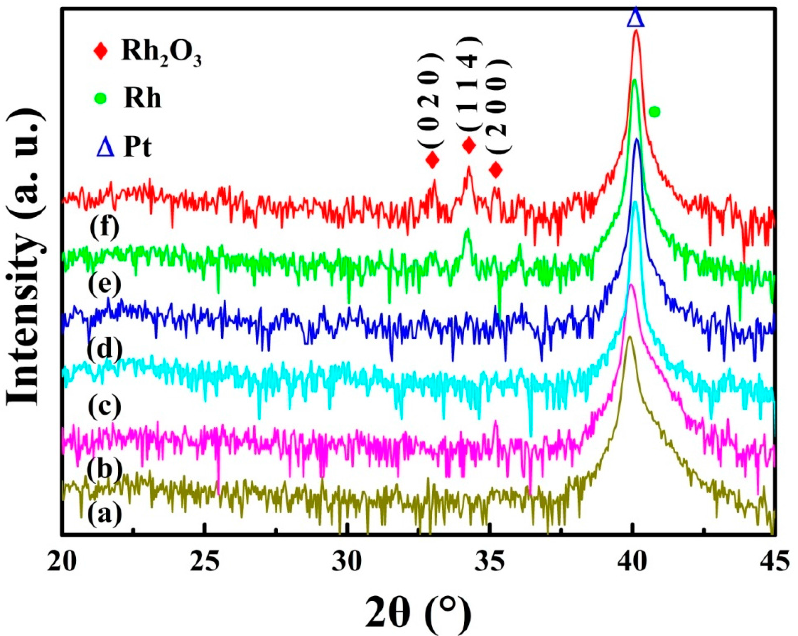
Figure 2 shows XRD patterns in log scale of as-deposited and annealed PtRh films. In as-deposited films, there are only diffraction peaks of platinum and rhodium. After annealing at 900 °C, (020), (114), and (200) diffraction peaks of rhodium oxide were found. However, these peaks were not observed in the films annealed at 1000 °C.
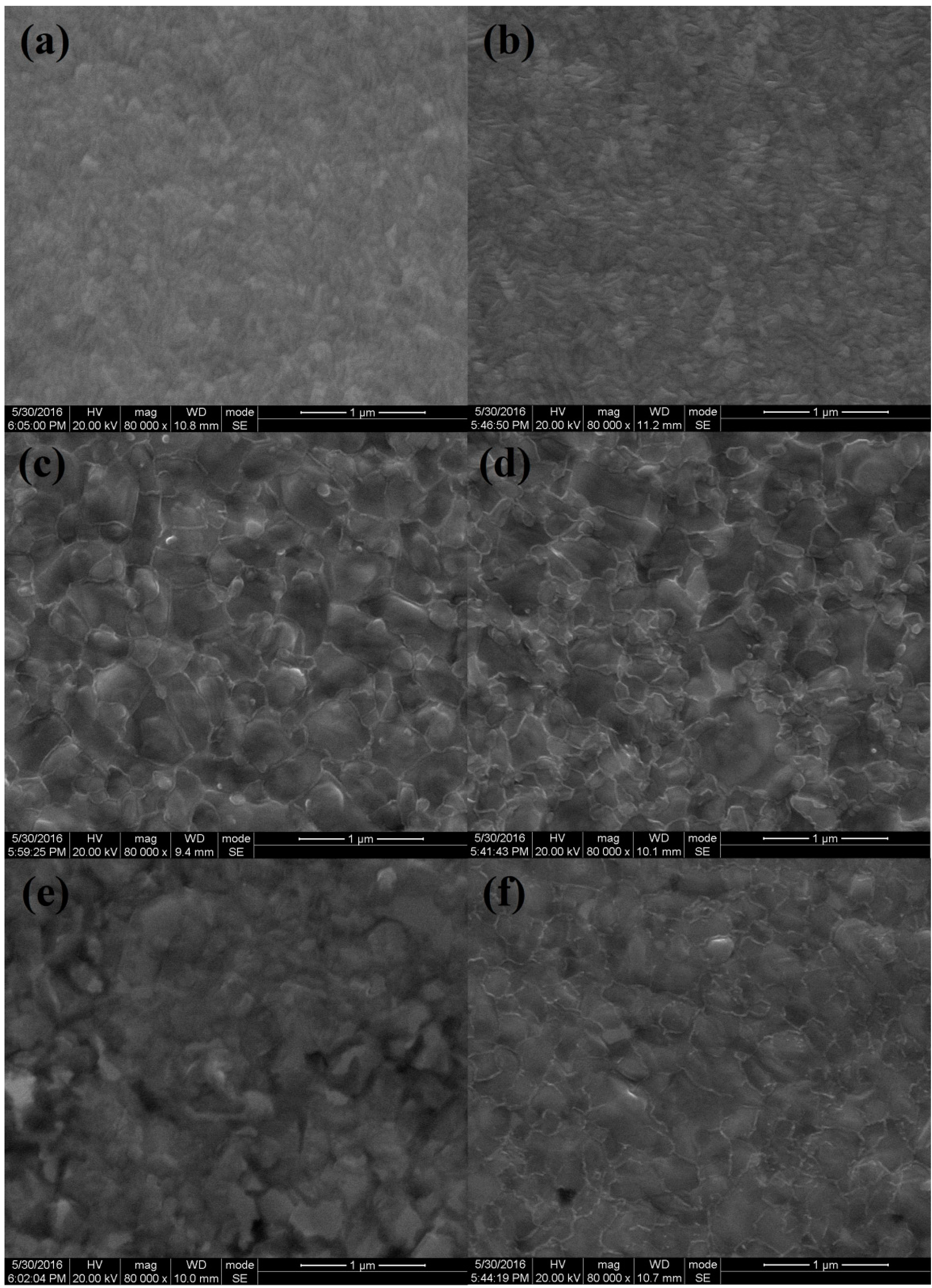
Figure 3 shows SEM observation of as-deposited and annealed PtRh films. All of the films were dense and smooth without any cracks or pinholes, and the grain size of the as-deposited film was quite even and less than 100 nm. After annealing at 900 °C, the grain size of the film increased significantly to about 250 nm. However, with further increasing annealing temperature, the grain size of both films did not show obvious increment.
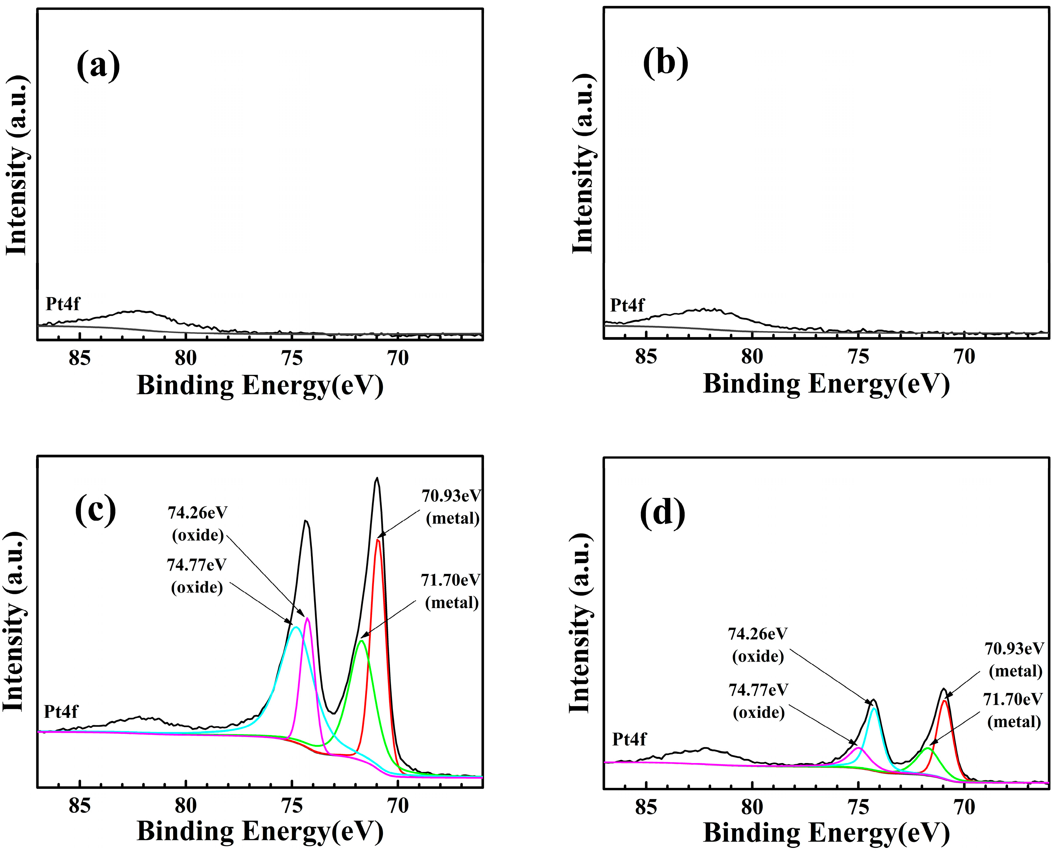
Figure 4 showed Pt 4f XPS spectra of annealed PtRh films, and the EDS elemental analysis results of the films are shown in Table 1. The calculated atomic ratios of PtRh alloy are also included for comparison.
It can be seen from Figure 4 that there was seldom any Pt 4f peak in the films annealed at 900 °C, whereas obvious Pt 4f peaks were observed in the films annealed at 1000 °C, and the peak intensity of Pt-10%Rh film was much stronger than that of Pt-13%Rh film. EDS analysis of the films is shown in Table 1. Compared with the initial composition, the atomic ratio of rhodium increased significantly, especially in the films annealed at 900 °C. This result suggests severe segregation of rhodium at the surface of the film. Meanwhile, a high atomic ratio of oxygen was observed, indicating that the surface of the film is oxidized, which is consistent with XRD results. As for the films annealed at 1000 °C, the atomic ratio of platinum increased in both films—especially in Pt-10%Rh film, in which platinum was 10% more than that of Pt-13%Rh film. This result is also verified by much stronger Pt 4f peak intensity of Pt-10%Rh film than that of Pt-13%Rh film. All of the observations imply that after annealing at 900 °C, rhodium tends to segregate at the surface of the film and form rhodium oxide by reacting with oxygen in the environment. This oxide layer inhibits further oxidation of the inner elements. With increasing annealing temperature, the Gibbs free energy for Rh2O3 may go to a lower value than the heat of solution of Rh in Pt [11,12]. As a result, rhodium oxide at the surface could be reduced, leading to the annihilation of XRD diffraction peaks of rhodium oxide in 1000 °C-annealed films. A higher content of rhodium in Pt-13%Rh films may lead to thicker rhodium segregation at the surface, and this explains the relatively lower platinum content in 1000 °C-annealed Pt-13%Rh films.
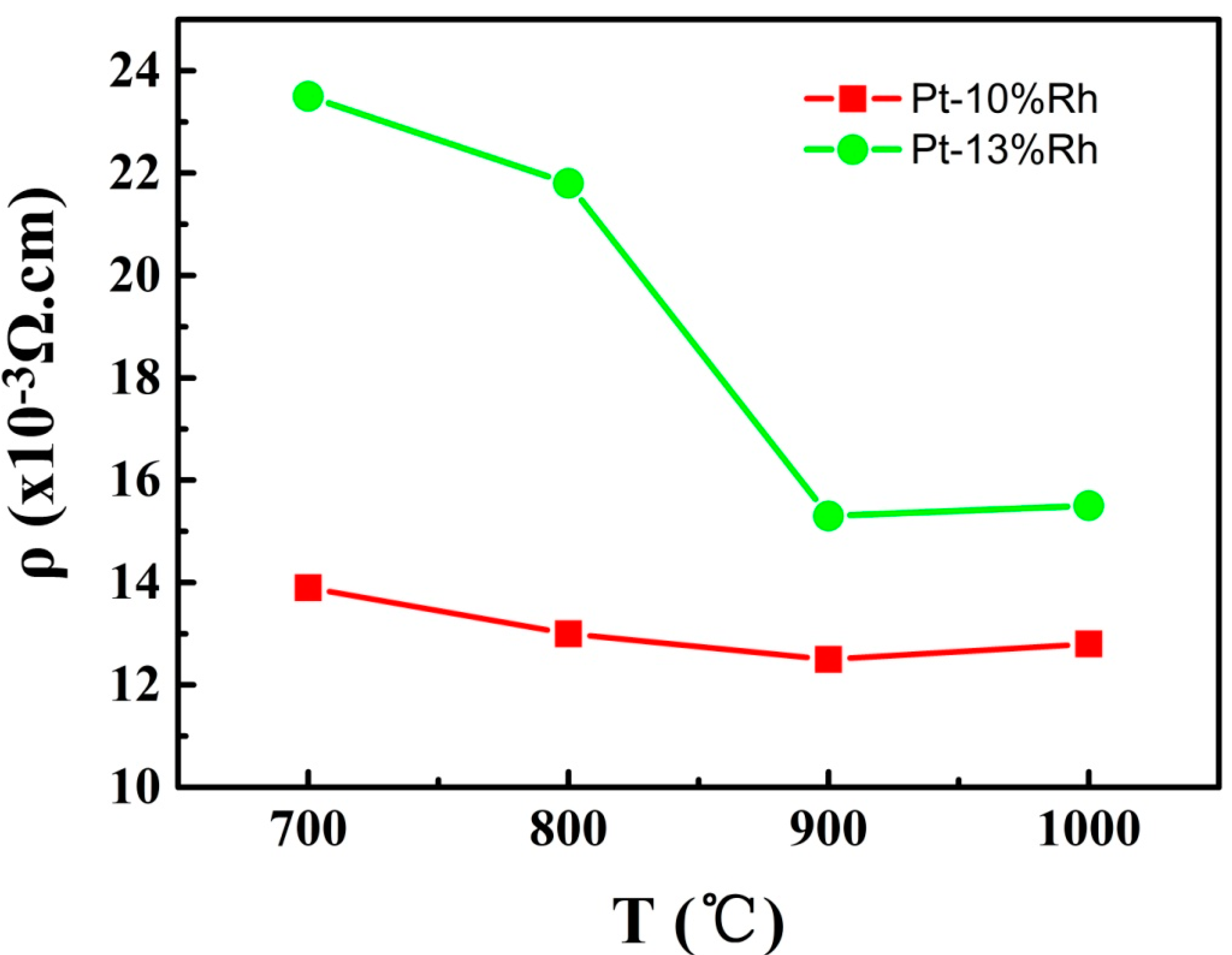
Figure 5 shows the variation of resistivity of both PtRh films with annealing temperature. The resistivity of both films decreased with increasing annealing temperature. This is related with the annihilation of the point defects and grain boundary [13]. The grain size of both films increased after annealing at high temperature, resulting in less grain boundary inside the films. Annealing is also helpful to reduce the point defects in the films. Both of these factors contribute to the decrement of the resistivity.
3.2. Thermoelectric Property of Type S and Type R TFTC
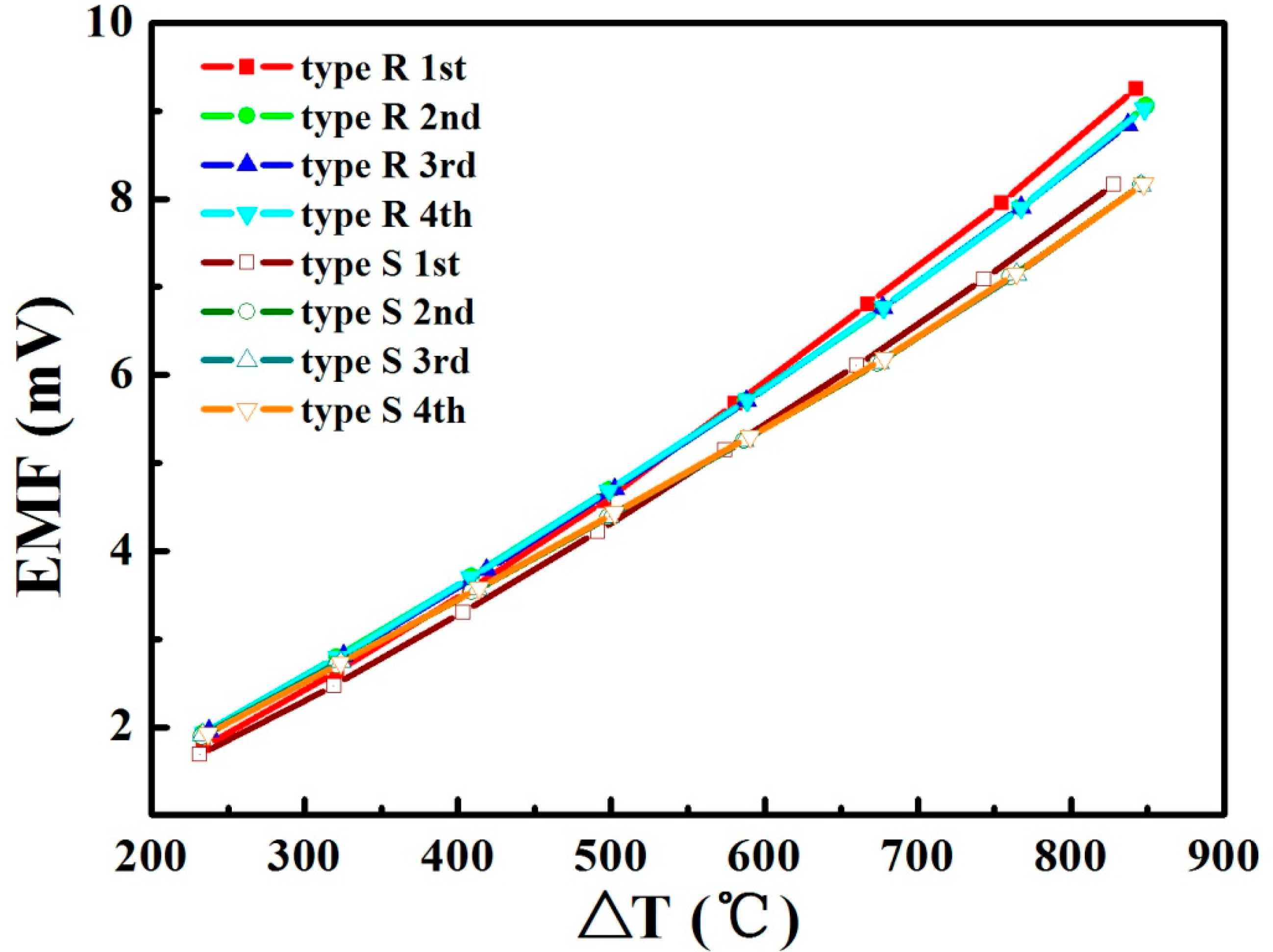
Type S and Type R TFTCs were fabricated on alumina substrate with magnetron sputtering, in which the negative element was Pt film and the positive element was Pt-10%Rh and Pt-13%Rh film, respectively. Both of the TFTCs had excellent adhesion on alumina substrates; the calibration results of type S and type R TFTCs are shown in Figure 6. The electric motive force (EMF) of both TFTCs increased linearly with temperature difference between the hot junction and bond pad. For Pt-based thermocouples, the relationship between thermoelectric response and temperature difference can be described by the following polynomial expression:
where ΔT is the applied temperature difference between hot junction and bond pad of TFTCs, and A, B, and C are polynomial constants. C is arbitrarily set to zero since the boundary condition (E(ΔT) = 0 if ΔT = 0) must be satisfied. The fitting results are shown in Table 2. All R2 values for all curve fittings are >0.995.
E(ΔT) = A(ΔT)2 + BΔT + C
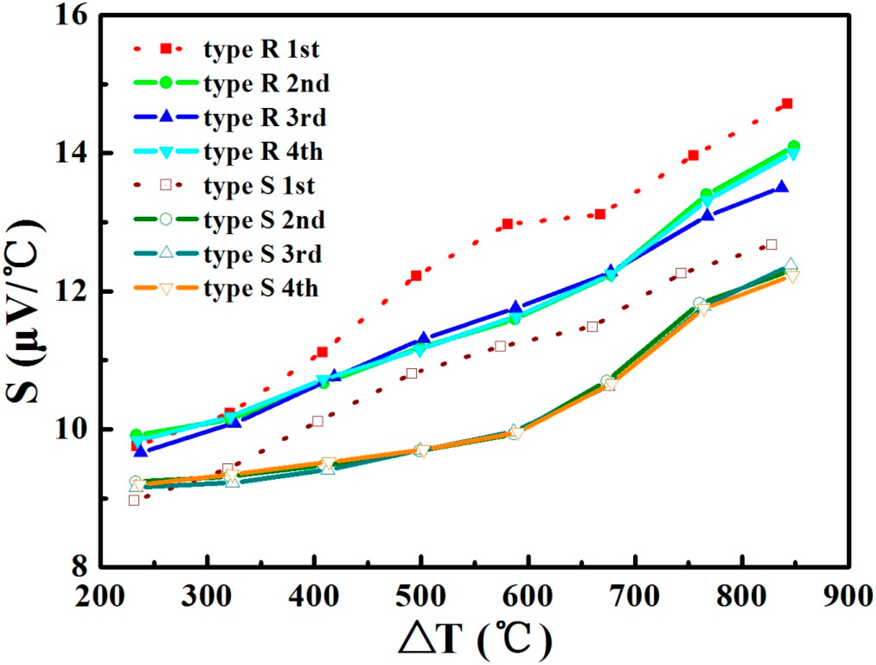
The slope of the EMF at a certain temperature is the Seebeck coefficient of the TFTC. The Seebeck coefficient of type S and type R TFTC is shown in Figure 7. Except for the first cycle, in which the films are as deposited without annealing, the output of the thermopower of all TFTCs reached more than 90% of their wire counterparts. Undoubtedly, the surface segregation and oxidation of rhodium lessens the thermoelectric potential of the positive element of TFTCs. Furthermore, this thermopower reduction is believed to be correlated with the size effect of thin films.
Where SB is the thermopower of bulk material, l is the mean free path of carriers, t is the film thickness, p is the scattering coefficient, and ξ is the Fermi energy. It is believed that the size effect of the metal film can be observed when the thickness of the film is comparable to the mean free path of carriers, and the electronic thermopower is independent of film thickness when the film thickness t » l. The thickness of Pt and PtRh films was 1 μm, which is not supposed to be able to induce severe size effect; however, the grain size of Pt and PtRh is small compared with the mean free path of charge carriers in bulk solid (usually higher than 200 nm). The segregation of rhodium at the surface and grain boundary in the films may form an additional potential barrier for carrier transportation, resulting in reduced mean free path of the carriers [15]. All of these factors contribute to the reduced Seebeck coefficient of type S and type R TFTCs.
The average Seebeck coefficient is 11.5 μV/°C for type R TFTC, which is larger than 10.1 μV/°C of type S TFTC. Additionally, there was only negligible difference between different calibration cycles, indicating excellent stability and repeatability of TFTCs. Except for the first calibration cycle, the variation of the Seebeck coefficient as a function of temperature difference of type R TFTC demonstrates better linearity than that of type S TFTC. We believe that the high temperature stability of TFTC can be ascribed to the surface segregation of rhodium. A thicker rhodium oxide layer could be formed in type R TFTC, and the oxidation at the grain boundary of the inner PtRh alloy—which inhibits the carrier transportation—was significantly reduced. As a result, the Seebeck coefficient of TFTC was well preserved. Due to the same mechanism, vacuum annealing—which is also helpful to introduce surface segregation of rhodium—was proven to be helpful for the stability enhancement of type S TFTC [4]. Furthermore, both of the TFTCs survived after several calibration cycles, meaning that the lifetime of both TFTCs is more than 20 h in highly oxidized environment with severe temperature ramps.
4. Conclusions
Pt-10%Rh and Pt-13%Rh films were prepared with magnetron sputtering. Their grain size increased after annealing at high temperature, resulting in the reduction of the resistivity. Rhodium tends to segregate at the surface of the film and form an oxide, leading to thermoelectric property variation of PtRh films. Type S and type R TFTCs were fabricated and statically calibrated for multiple thermal cycles. Type R TFTCs demonstrated improved high temperature stability and repeatability with larger Seebeck coefficient, making them a more promising candidate for the surface temperature measurement of hot components of engines.
Acknowledgments
We gratefully acknowledge the support of National Natural Science Foundation of China (No. 61223002) and Program for Cooperation of Industry, Education and Academy of Guangdong Province, China (No. 2013B090400001).
Author Contributions
Xiaohui Zhao conceived and designed the experiments; Xianguai Liang fabricated and characterized the TFTCs; Shuwen Jiang and Wanli Zhang collaborated in XRD and XPS measurements; Hongchuan Jiang analyzed the data. All authors discussed the experiment results and contributed to writing the paper.
Conflicts of Interest
The authors declare no conflict of interest.
References
- Zhao, X.; Li, H.; Yang, K.; Jiang, S.; Jiang, H.; Zhang, W. Annealing effects in ito based ceramic thin film thermocouples. J. Alloys Compd. 2017, 698, 147–151. [Google Scholar] [CrossRef]
- Zhao, X.; Wang, Y.; Chen, Y.; Jiang, H.; Zhang, W. Enhanced thermoelectric property and stability of nicr-nisi thin film thermocouple on superalloy substrate. Rare Metals 2016. [Google Scholar] [CrossRef]
- Zhao, X.; Yang, K.; Wang, Y.; Chen, Y.; Jiang, H. Stability and thermoelectric properties of iton:Pt thin film thermocouples. J. Mater. Sci. Mater. Electron. 2016, 27, 1725–1729. [Google Scholar] [CrossRef]
- Chen, Y.; Jiang, H.; Zhao, W.; Zhang, W.; Liu, X.; Jiang, S. Fabrication and calibration of pt-10%rh/pt thin film thermocouples. Measurement 2014, 48, 248–251. [Google Scholar] [CrossRef]
- Tougas, I.M.; Gregory, O.J. Thin film platinum-palladium thermocouples for gas turbine engine applications. Thin Solid Films 2013, 539, 345–349. [Google Scholar] [CrossRef]
- Tougas, I.M.; Amani, M.; Gregory, O.J. Metallic and ceramic thin film thermocouples for gas turbine engines. Sensors 2013, 13, 15324–15347. [Google Scholar] [CrossRef] [PubMed]
- Liu, H.; Sun, W.; Xu, S. An extremely simple thermocouple made of a single layer of metal. Adv. Mater. 2012, 24, 3275–3279. [Google Scholar] [CrossRef] [PubMed]
- Kreider, K.G.; Gillen, G. High temperature materials for thin-film thermocouples on silicon wafers. Thin Solid Films 2000, 376, 32–37. [Google Scholar] [CrossRef]
- Zhao, X.; Li, H.; Chen, Y.; Jiang, H. Preparation and thermoelectric characteristics of ito/pt thin film thermocouples on ni-based superalloy substrate. Vacuum 2016. [Google Scholar] [CrossRef]
- Kreider, K.G.; DiMeo, F. Platinum/palladium thin-film thermocouples for temperature measurements on silicon wafers. Sens. Actuators A Phys. 1998, 69, 46–52. [Google Scholar] [CrossRef]
- Kreider, K.G. Sputtered high temperature thin film thermocouples. J. Vac. Sci. Technol. A 1993, 11, 1401–1405. [Google Scholar] [CrossRef]
- Barin, I. Thermochemical Data of Pure Substances; VCH: New York, NY, USA, 1995. [Google Scholar]
- Sreemany, M.; Sen, S. Effect of substrate temperature and annealing temperature on the structural, electrical and microstructural properties of thin pt films by rf magnetron sputtering. Appl. Surf. Sci. 2006, 253, 2739–2746. [Google Scholar] [CrossRef]
- Scarioni, L.; Castro, E. Thermoelectric power in thin film fe-cuni alloy (type-j) couples. J. Appl. Phys. 2000, 87, 4337–4339. [Google Scholar] [CrossRef]
- Boukai, A.I.; Bunimovich, Y.; Tahir-Kheli, J.; Yu, J.-K.; Goddard Iii, W.A.; Heath, J.R. Silicon nanowires as efficient thermoelectric materials. Nature 2008, 451, 168–171. [Google Scholar] [CrossRef] [PubMed]
Figure 1.
Photograph of thin film thermocouple (TFTC) and schematic of the calibration setup.

Figure 2.
XRD patterns of as-deposited and annealed PtRh films: (a) as deposited Pt-10%Rh films; (b) as-deposited Pt-13%Rh films; (c) Pt-10%Rh films annealed at 1000 °C/1 h; (d) Pt-13%Rh films annealed at 1000 °C/1 h; (e) Pt-10%Rh films annealed at 900 °C/1 h; (f) Pt-13%Rh films annealed at 900 °C/1 h.

Figure 3.
SEM photograph of PtRh films: (a) as-deposited Pt-10%Rh films; (b) as-deposited Pt-13%Rh films; (c) Pt-10%Rh films annealed at 900 °C/1 h; (d) Pt-13%Rh films annealed at 900 °C/1 h; (e) Pt-10%Rh films annealed at 1000 °C/1 h; (f) Pt-13%Rh films annealed at 1000 °C/1 h.
Figure 3.
SEM photograph of PtRh films: (a) as-deposited Pt-10%Rh films; (b) as-deposited Pt-13%Rh films; (c) Pt-10%Rh films annealed at 900 °C/1 h; (d) Pt-13%Rh films annealed at 900 °C/1 h; (e) Pt-10%Rh films annealed at 1000 °C/1 h; (f) Pt-13%Rh films annealed at 1000 °C/1 h.

Figure 4.
High resolution Pt 4f X-ray photoelectron spectroscopy (XPS) spectra for PtRh films annealed at different temperatures: (a) Pt-10%Rh films annealed at 900 °C/1 h; (b) Pt-13%Rh films annealed at 900 °C/1 h; (c) Pt-10%Rh films annealed at 1000 °C/1 h; (d) Pt-13%Rh films annealed at 1000 °C/1 h.

Figure 5.
The variation of resistivity of PtRh films with annealing temperature.

Figure 6.
The electric-motive force of type S and type R TFTCs.

Figure 7.
Seebeck coefficient of type S and type R TFTC.


Table 1.
EDS elemental analysis of PtRh films.
| Samples | Atomic % | ||
|---|---|---|---|
| Pt | Rh | O | |
| Pt-10%Rh annealed at 900 °C | 26.15 | 21.00 | 52.86 |
| Pt-13%Rh annealed at 900 °C | 24.97 | 23.61 | 51.42 |
| Pt-10%Rh annealed at 1000 °C | 44.84 | 17.95 | 37.21 |
| Pt-13%Rh annealed at 1000 °C | 34.08 | 16.27 | 49.65 |
| Pt-10%Rh alloy | 94.46 | 5.54 | 0 |
| Pt-13%Rh alloy | 92.69 | 7.31 | 0 |
Table 2.
Polynomial fitting of thermopower of type S and type R TFTCs.
| Coefficients of Polynomial V(T) = A(ΔT)2 + BΔT + C | ||||
|---|---|---|---|---|
| Thermocouple | A (mV/°C2) | B (mV/°C) | C (mV) | Average Seebeck Coefficient (µV/°C) |
| Type S standard | 2.79 × 10⁻⁶ | 7.82 × 10⁻³ | 0 | 10.81 |
| Type S 1st cycle | 4.00 × 10⁻⁶ | 6.58 × 10⁻³ | 0 | 10.88 |
| Type S 2nd cycle | 2.34 × 10⁻⁶ | 7.61 × 10⁻³ | 0 | 10.12 |
| Type S 3rd cycle | 2.27 × 10⁻⁶ | 7.66 × 10⁻³ | 0 | 10.08 |
| Type S 4th cycle | 2.29 × 10⁻⁶ | 7.65 × 10⁻³ | 0 | 10.11 |
| Type R standard | 4.16 × 10⁻⁶ | 7.81 × 10⁻³ | 0 | 12.26 |
| Type R 1st cycle | 5.20 × 10⁻⁶ | 6.65 × 10⁻³ | 0 | 12.30 |
| Type R 2nd cycle | 3.44 × 10⁻⁶ | 7.78 × 10⁻³ | 0 | 11.52 |
| Type R 3rd cycle | 3.70 × 10⁻⁶ | 7.48 × 10⁻³ | 0 | 11.50 |
| Type R 4th cycle | 3.66 × 10⁻⁶ | 7.53 × 10⁻³ | 0 | 11.52 |
© 2017 by the authors. Licensee MDPI, Basel, Switzerland. This article is an open access article distributed under the terms and conditions of the Creative Commons Attribution (CC BY) license (http://creativecommons.org/licenses/by/4.0/).
Share and Cite
MDPI and ACS Style
Zhao, X.; Liang, X.; Jiang, S.; Zhang, W.; Jiang, H. Microstructure Evolution and Thermoelectric Property of Pt-PtRh Thin Film Thermocouples. Crystals 2017, 7, 96. https://0-doi-org.brum.beds.ac.uk/10.3390/cryst7040096
AMA Style
Zhao X, Liang X, Jiang S, Zhang W, Jiang H. Microstructure Evolution and Thermoelectric Property of Pt-PtRh Thin Film Thermocouples. Crystals. 2017; 7(4):96. https://0-doi-org.brum.beds.ac.uk/10.3390/cryst7040096
Chicago/Turabian StyleZhao, Xiaohui, Xianguai Liang, Shuwen Jiang, Wanli Zhang, and Hongchuan Jiang. 2017. "Microstructure Evolution and Thermoelectric Property of Pt-PtRh Thin Film Thermocouples" Crystals 7, no. 4: 96. https://0-doi-org.brum.beds.ac.uk/10.3390/cryst7040096
Note that from the first issue of 2016, this journal uses article numbers instead of page numbers. See further details here.