Article

An Optical Microscope Study of the Morphology of Xenon Hydrate Crystals: Exploring New Approaches to Cryopreservation

1
Institute of Cell Biophysics of the Russian Academy of Sciences, PSCBR RAS, Pushchino 142290, Russia
2
Advanced Research Foundation, Moscow 83843, Russia
*
Author to whom correspondence should be addressed.
Submission received: 30 March 2019 / Revised: 16 April 2019 / Accepted: 17 April 2019 / Published: 20 April 2019

Abstract

:
One of the possible approaches to a new method of cryopreservation seems to be the controlled formation of a multitude of small crystals in an object, which, due to their size, will not damage cellular structures. Managing the crystal formation, given the stochastic nature of the process, is an extremely difficult task. Theoretically, it is simplified if there is a sufficient number of changeable physical parameters, affecting the process. From this point of view, the use of ice-like gas hydrates for the purposes of cryopreservation seems to be a promising option. We investigated the process of growth of xenon gas hydrates via standard microscopy under different conditions using the specialized optical cell for observation at elevated pressures. The formation of crystals was observed in the system “supercooled liquid–xenon–water vapor” at negative, near-zero and positive values of temperature, and pressure of xenon up to 8 atmospheres. The morphology of xenon hydrate crystals observed in the experiments was analyzed and classified into five categories. The influence of physical conditions on the predominant crystal morphology was also studied. We found no evidence that the possible damaging effect of hydrate crystals should be less severe than of ice crystals.

1. Introduction

Currently, cryopreservation methods are widely used in science, medicine, agriculture, and biotechnology. There is an active search for a new effective method of cryopreservation, which would allow the cryopreservation of large biological objects—large tissue volumes and organs. Cooling bio-objects below 0 °C is associated with the formation of ice crystals and mechanical damage to cell membranes, which causes cell death. As a part of the search for new directions for the further development of cryopreservation technologies, the idea of using gas hydrates for cryopreservation was born in the late 60s [1].
Gas hydrates are ice-like substances, the crystalline framework of which are composed of water molecules linked to one another by hydrogen bonds. The framework contains cavities (cages), which accommodate guest molecules. The guest molecules in gas hydrates should be 0.38–0.92 nm in diameter and can be represented by inert gas atoms, lower hydrocarbon molecules, Freon molecules and so on [2,3]. Theoretically, the inert gas atoms could be considered candidates for controlled formation of a multitude of small crystals in an object, which, due to their size (no more than an estimated 300–400 nm), will not damage cellular structures. In contrast to classical cryoprotectants, inert gases are non-toxic and freely pass through cell membranes. When using gas hydrates, there are more opportunities (pressure, the ratio of water and gas, the use of mixtures of gases, etc.) to influence the process of crystal formation.
Xenon is the most promising hydrate-forming gas to date. It forms hydrate in mild conditions, slightly below the freezing point of water, at −1 °C and 1.5 atmospheres (atm) [4]. Also, it can be obtained at positive temperatures and slightly elevated pressure in the absence of ice, which is crucial to distinguish between ice and hydrate effects. Xenon forms hydrate in crystal lattice type cubic structure I (CS-I) [2]. The unit cell of the body-centered cubic lattice CS-I contains 46 water molecules, which form 2 small and 6 large cavities (Figure 1). The crystal lattice parameter is α = 1.2 nm (defined for 0 °C). The xenon atom fills all large and about 70% of the small lattice cavities [5].
With a strong anesthetic effect, xenon is considered to be the best yet expensive inhalation anesthetic and is officially approved for application in several countries including Russia and Germany. Finally, xenon has been used in a limited number of cryobiological studies with positive effects [6,7,8,9,10,11]. One of the leading ideas that is repeated in these works is the less traumatic effect of gas hydrates compared to ice. In fact, gas hydrates have a looser structure, and the geometry of the crystals of gas hydrates more resembles the safer cubic ice than hexagonal ice. We can expect that the mechanical damage to cells that is caused by gas hydrate crystals will be lower compared to the action of ice crystals. But this hypothesis should be confirmed at the microscopic level.
Since the main components of the hydrate formation process are water and gas molecules, at the initial stage it seems reasonable to model the formation of a hydrate in aqueous solutions and biological fluids with a detailed study of the size and morphology of gas hydrate crystals. For the formation of gas-hydrate sites, it is necessary to create the driving force of the process, namely, exceeding the gas pressure above the equilibrium or lowering the temperature below the equilibrium. Due to the delayed nucleation of the hydrate, the liquid under the pressure of the gas-forming hydrate may exist in a metastable state for a long time. This time depends on the temperature of the metastable liquid, the gas pressure, the presence of heterogeneous nucleation centers in the liquid and their activity [2,12,13,14,15,16,17,18,19].
In the present study, we focus on the microscopic evaluation of morphological forms of xenon hydrate crystals obtained under various conditions.

2. Materials and Methods

2.1. Preparation of Xenon Hydrates

Xenon hydrates were obtained in a titanium chamber with an observation window (Figure 2). The chamber was placed into a thermostable jacket connected to continuous circulation chiller (Huber Ministat 230 w, Huber, Offenburg, Germany). The gas from a high-pressure cylinder was fed through a tube, connected to a pressure regulator (with an accuracy of 0.1 atm). The temperature of the chamber was monitored with a built-in thermocouple (with an accuracy of 0.1 °C).
A drop of high purity deionized water with a resistivity of 17 MΩ·cm (5–20 µL) was put on the inner surface of the lower observation window (diameter Ø = 20 mm) or on a special glass insert inside the main compartment, after which the residual air was removed by a slow xenon flow. After that, the xenon was forced into the main compartment to a pressure P = 5–8 atm (gauge pressure).
To form gas hydrates, the pressure chamber was placed in a thermostat at +4 °C for 12–32 h. A temperature of +4 °C was taken as the common hypothermic preservation temperature used for transplants. The equilibrium conditions of xenon hydrate formation are +4 °C/2.3 atm and +15 °C/8 atm [20].
If gas hydrates were not formed within the specified time their formation was initiated by the additional cooling of the chamber to a temperature in the range of 0 to −14 °C. The use of a thermostatically controlled pressure chamber allowed us to carry out observations under conditions of controlled values of temperature and pressure. The study of the morphology of xenon hydrates was carried out in the temperature range of −14 to + 25 °C.

2.2. Visual Examination of Gas Hydrate Samples by Microscopy

The microscopes used were a Leica MZ16A stereomicroscope (Leica, Wetzlar, Germany), a ZEISS LSM 510 META laser scanning confocal microscope (Axioplan 2 Imaging microscope, Carl Zeiss, Jena, Germany), a Leica TCS SP5 (Leica, Wetzlar, Germany) laser scanning confocal microscope, and an Axio Imager Z1 universal research microscope (Carl Zeiss, Jena, Germany). Also, a wide range of lenses were used. This allowed us to study crystals in the size range from a few microns to hundreds of microns.
With a laser scanning confocal microscope xenon hydrate crystal samples were studied in two observation modes, which included observation in reflected light at a wavelength of 488 nm and observation in transmitted light using a differential interference contrast (DIC) method. The study of xenon hydrates on a stereomicroscope was carried out according to the method of transmitted light and side-illumination.
So that the atmospheric moisture did not condense on the viewing window and did not degrade the image of the test sample, observations were made through a thin layer of ethanol, which was applied to the external surface of the upper observation window. To study the processes on the surface and in the internal volume of a water drop, various observation windows of the main compartment were used including quartz, glass, and leuco sapphire. Glass and quartz windows can be considered hydrophilic, while leuco sapphire windows are hydrophobic. The use of sapphire made it possible to investigate both the surface of the drop and its depth since a drop of water on the window surface assumes a spherical shape.
The processes of growth and decomposition of xenon hydrate crystals were controlled by the smooth regulation of temperature and pressure and were observed using a microscope.

3. Results

3.1. The Induction Time of Xenon Hydrate Formation

The nucleation of a solid phase is the limiting stage of the formation and growth of xenon hydrates from a drop of liquid water. The time interval between the moment when the system (liquid + hydrate-forming agent) becomes metastable, and the moment when the onset of hydrate formation is detected (induction time) is a highly random variable, which is clearly confirmed in the present work. The observed induction time of xenon hydrate varied from several minutes to several days in a series of experiments under similar conditions (+4 °C, 8 atm). However, after the formation of the initial hydrate masses, a rapid growth of xenon hydrates was observed. Figure 3 shows the hydrate growth after the initial formation with a linear growth rate that was in the range of 10–30 μm/min (Figure 3).

3.2. The Variety of Morphological Forms of Xenon Hydrate under Different Conditions

The initial stage of any experiment involved a supercooling period under the same conditions at +4 °C and 8 atm, mainly for 8–16 h. If there was no hydrate observed we performed additional cooling until the phase transition took place. It was shown that under similar conditions a variety of different morphological forms of xenon hydrates were formed.

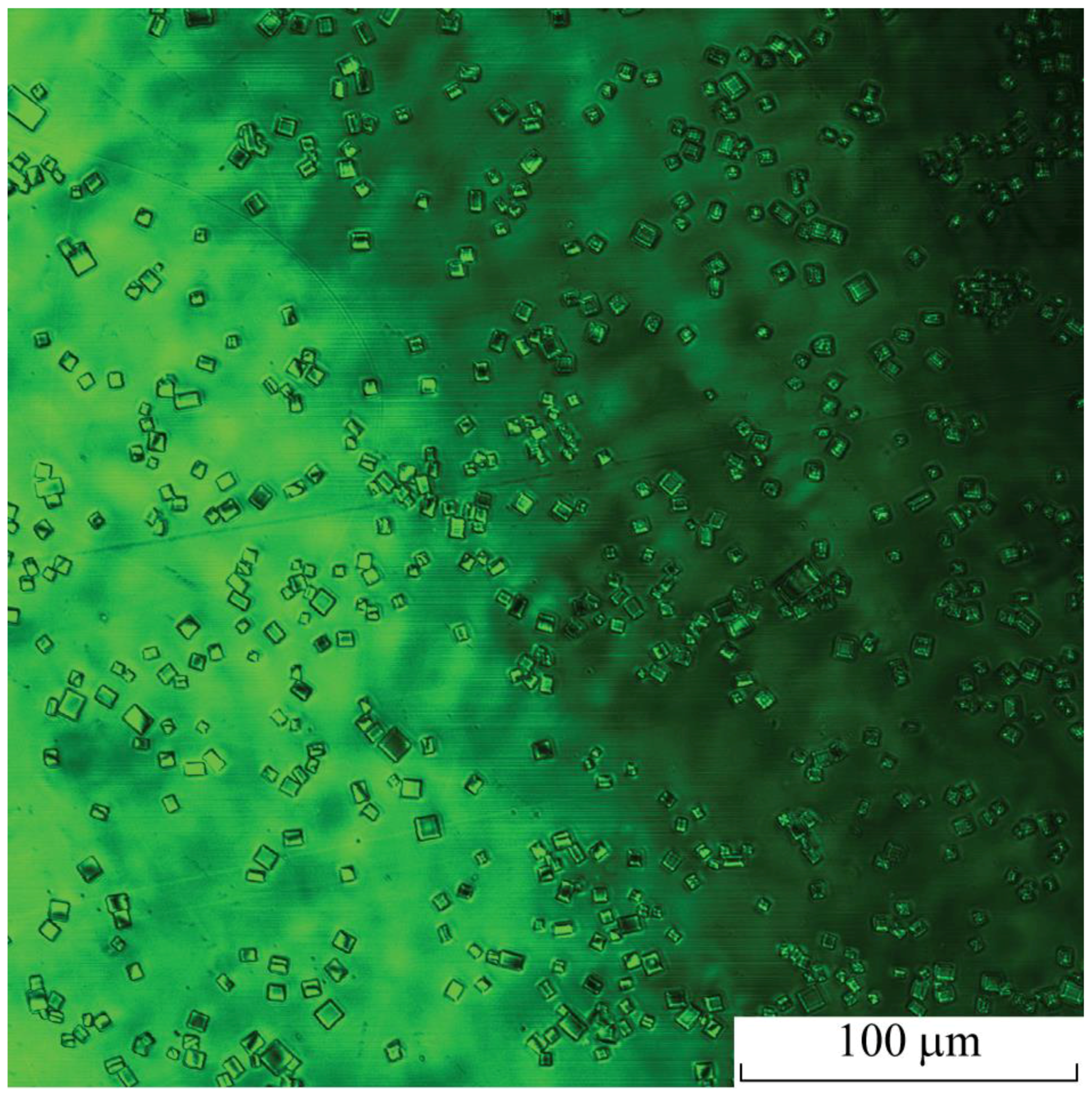
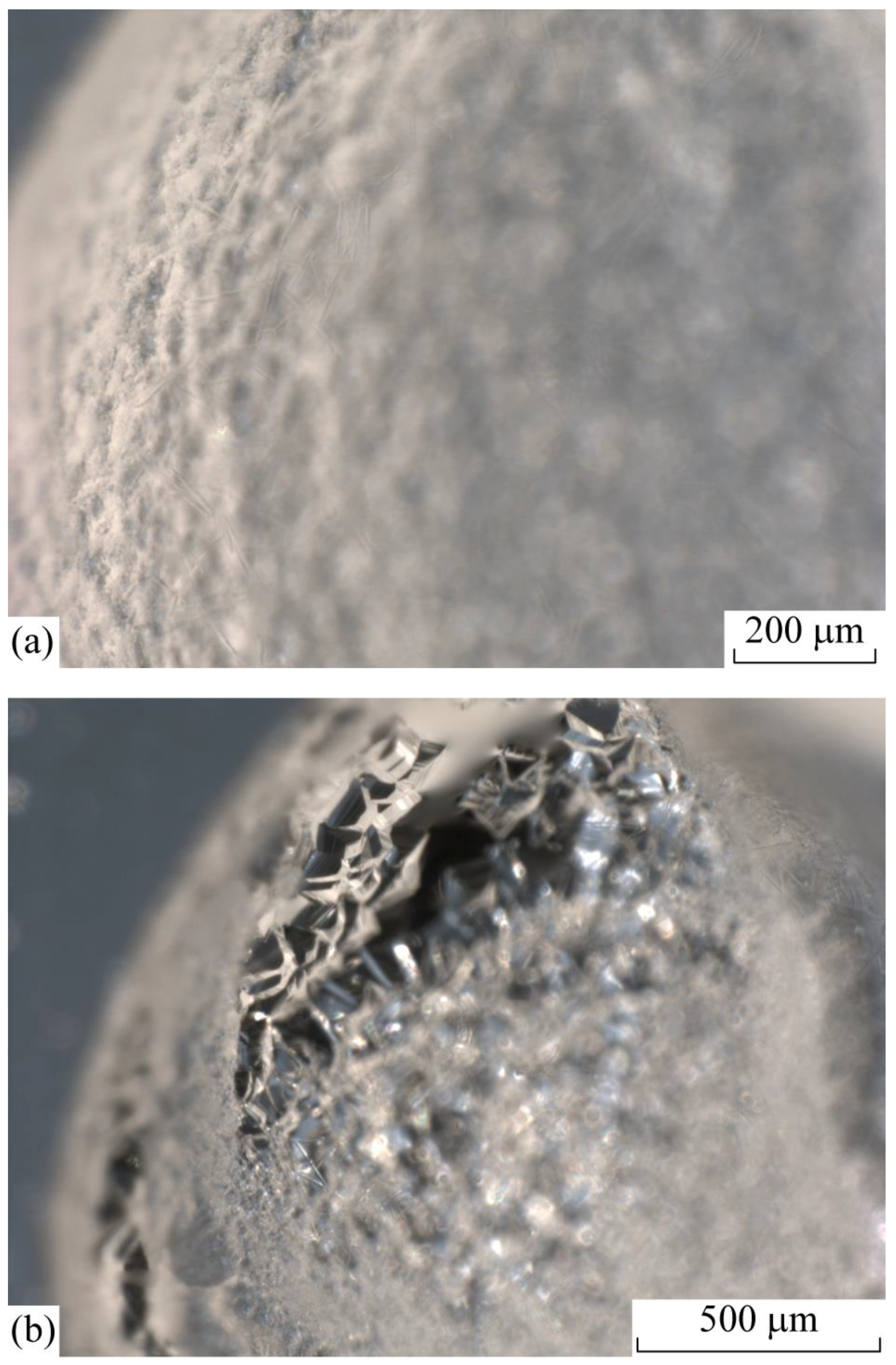
3.2.1. The Cubic Form of Xenon Hydrate

The cubic form is composed of single crystals or their separately arranged clusters (Figure 4 and Figure 5). Cubic crystals can be sized from 10 to 500 μm. These crystals may contain inclusions or the defects on the surface of crystal faces. (Figure 4a,b). This regular crystal type, which corresponds to the symmetry of the crystal lattice, can be formed under conditions that ensure slow crystal growth. For the experiment presented in Figure 5, the low growth rate was due to the slow condensation of water vapor. Water vapors were formed in the main compartment with gradual evaporation of a part of the liquid from the surface of the drop for 16–18 h at +4 °C, and partial decompression of the chamber from 8 to 2.3 atm.

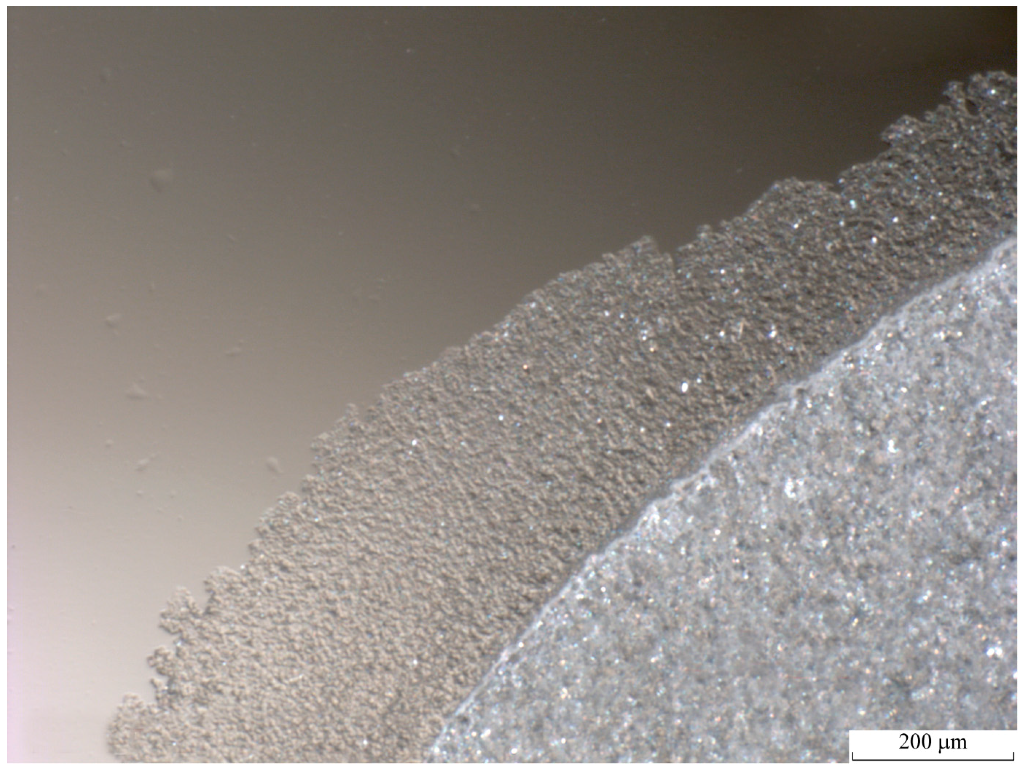
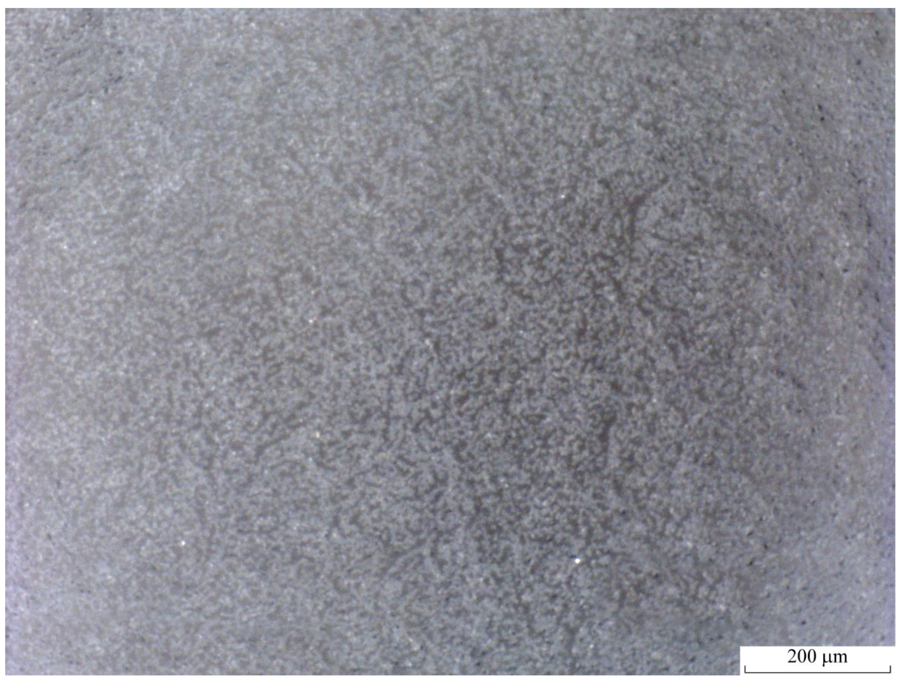
3.2.2. The Dense Fine-Grained Form of Xenon Hydrate

The dense fine-grained form is composed of elements no larger than 3–5 μm (Figure 6). These crystals were formed after an additional cooling stage at −10~–13 °C, p (Xe) = 8 atm in the drop applied to the inner surface of the hydrophilic observation window. With a sufficient amount of water vapor inside the pressure chamber, a thin dense layer of crystallites grew around the crystallized droplet (Figure 3 and Figure 6). The growth rate was proportional to the temperature and the partial pressure of water vapor.
As well known from the literature, in a stable water-gas interface (which is formed in the optical cell), as a rule, a more or less dense hydrate film is formed. This is due to the sticking of hydrate crystals formed on the surface. The growth of such films can proceed at a high rate—3–40 mm/min [21,22,23,24,25,26]. The thickness of the film formed is inversely proportional to the driving force of the process [27]. The morphology of the growth front of a hydrate film formed at small (less than 2 °C) and large supercooling differs significantly [28].

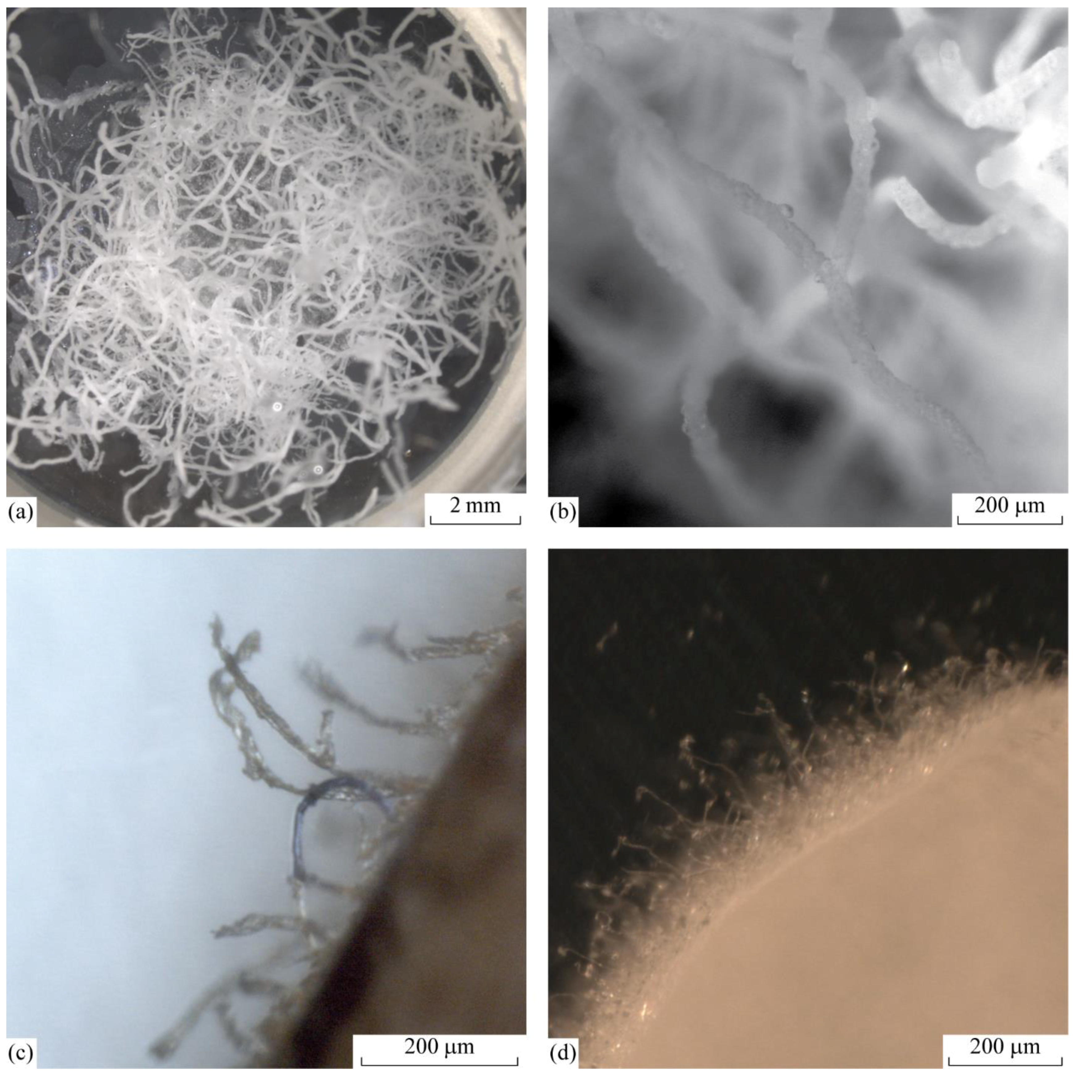
3.2.3. The Whisker Form of Xenon Hydrate

The whisker form (Figure 7) arose in the supercooled system (15 °C lower than equilibrium conditions). Large filamentous crystals were formed as curving outgrowths of considerable length (up to several mm) 30–100 μm width (Figure 7a). This form is a dense cluster of crystallites with a size of 5–15 µm, assembled into expanded structures (Figure 7b). The growth of this form was observed from a drop of 30–50 μL at a temperature of ~0 °C after an additional cooling stage and xenon pressure of 8 atm. The threads were oriented in random directions and can randomly bend at different angles. Growth occurs due to the formation of a solid phase at the free ends of the filaments through an intermediate liquid phase. The gas diffuses through a thin film of liquid and precipitates as a hydrate on the crystal surface. The growth rate is estimated at 100–300 μm/min.
Thin filamentous crystals are formed by chaotically curving thin outgrowths 10–20 μm width (Figure 7c,d). The formation of this form occured during the condensation of water vapor on the fresh surface of a crystallized drop both above and below 0 °C and at a xenon pressure of 5–8 atm. Often the fracturing of thin filaments could be observed, because of their own weight.

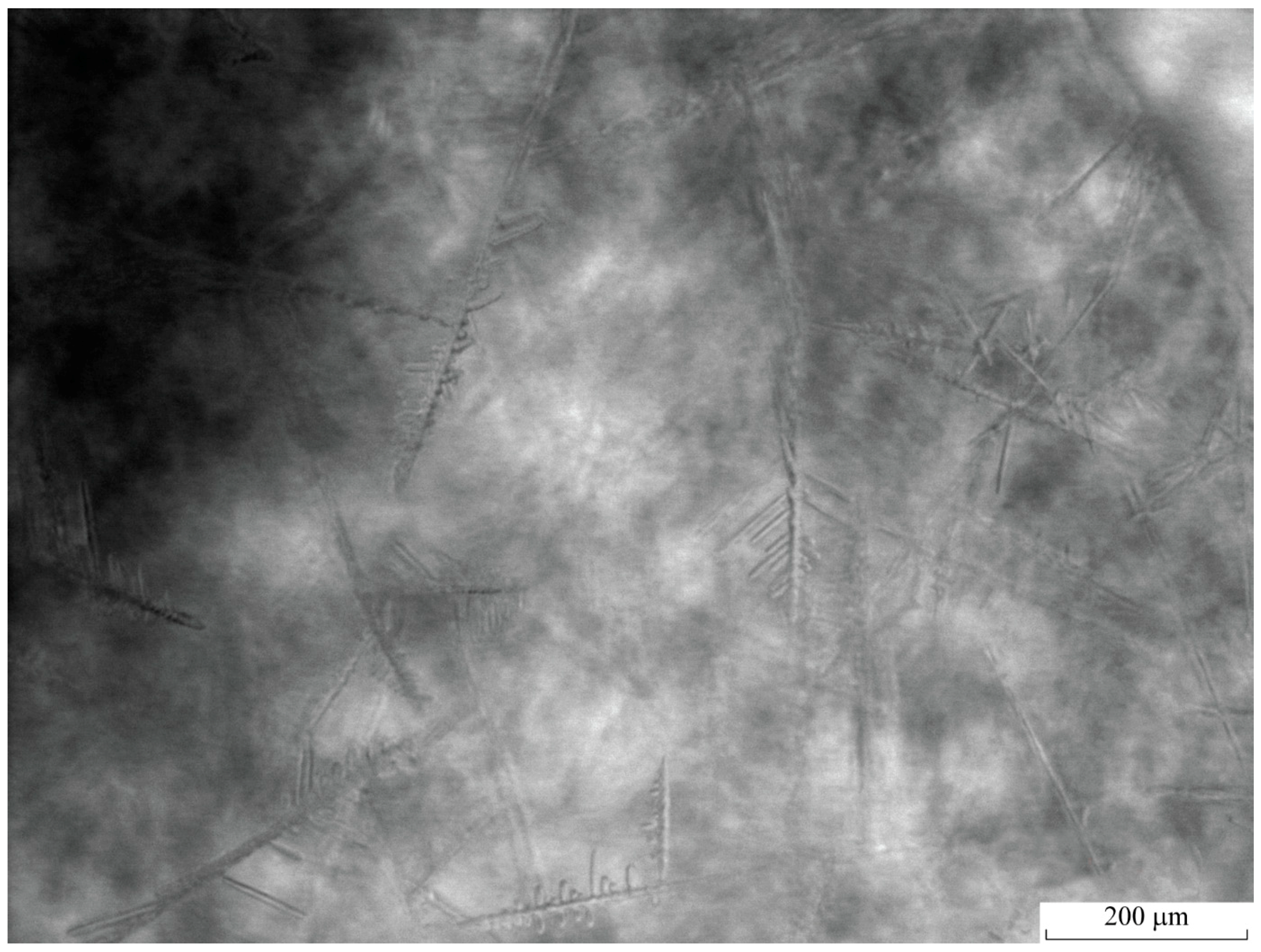
3.2.4. The Acicular form of Xenon Hydrate

The acicular form of xenon hydrate looks like a straight elongated thin crystal with a length of 100–300 μm and a width of 15–25 μm (Figure 8). The growth of this form was observed at a temperature of 0 °C in the process of an additional cooling from +4 °C to 0 °C and xenon pressure of 8 atm.
These dendrites up to several hundred μm in length emerge at the boundary of the surface of a fine-grained form and liquid.
From the literature, it is known that after coating the entire surface of the liquid with hydrate, a hydration film grows in thickness. As the thickness of the hydrate layer increases, the reaction rate decreases rapidly until it completely stops. The dependence of the growth rate of the hydration layer on the driving force is close to exponential and is controlled by heat removal [27,29]. With supercooling above 3 °C, the growing layer of methane or ethane hydrate consists of acicular and triangular crystallites [30]. A similar pattern is established for xenon hydrate.

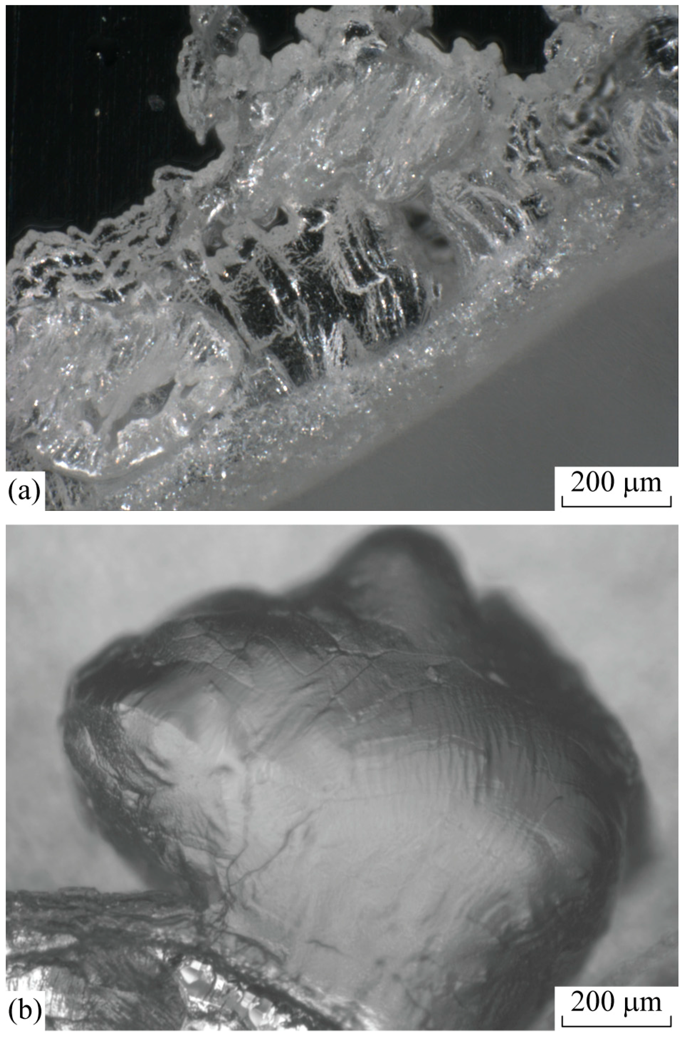
3.2.5. The Massive Form of Xenon Hydrate

The massive form cannot be clearly classified and may differ in appearance (Figure 9). This may be a matte or transparent crystal with no specific shape. With a pressure of xenon of 8 atm, the temperature of formation of a massive form can vary from −13 to +4 °C. Xenon hydrates in Figure 9 were formed at a temperature of −10 °C after an additional cooling step during the condensation of water vapor in the edge areas of a crystallized drop (Figure 9a) or inside a liquid supercooled drop (the direction of crystal growth was from the water gas interface into the liquid) (Figure 9b).
In our study, we observed many experiments with the prevalence of one particular morphological form. At the same time, several morphological types of xenon hydrate could coexist simultaneously during one experiment. Figure 10 shows the example of a mixed sample with fine-grained, filamentous and massive forms (Figure 10).

3.3. The Prospect of Extremely Rapid Cooling to Obtain Small Sized Xenon Hydrate Crystals

All of the morphological types of xenon hydrates described above were formed in «mild conditions» with a low cooling rate (1–5 °C/min) and overcooling, not more than 10–25 °C. We found no evidence that the possible damaging effect of observed hydrate crystals should be less severe than that of ice crystals. The initial model for biological experiments with hydrate preservation seems to be cell suspensions. We believe that the formation of crystal forms observed in this work (for example needle-shaped crystals) in the extracellular environment will mechanically damage the cells (the safe formation of hydrates inside the cell is an even more complicated matter). However, at high cooling rates to a temperature of −100 °C in 1–2 s, fine-grained crystals of xenon hydrate (Figure 11) with a grain size of ~1–5 μm form. The formation of xenon hydrate was initiated by rapid deep cooling of the sapphire observation window, on which there was a drop of water saturated with xenon. Ethyl alcohol cooled with liquid nitrogen to −100 ± 5 °C was applied to the external surface of the observation window, which caused phase transition. The crystalline phase available for observation had a fine-grained structure with the size of individual elements no more than 5 μm. The temperature of the sapphire window within 10 min returned to +4 °C. During this time, no notable change occurred in crystal image. Additional observation at the positive temperatures for one hour also did not reveal any significant transformation. We do not have exact data to answer the question of which phase arose initially—water ice or xenon hydrate or numerical value of ice/hydrate ratio, also we believe that this ratio is more on the hydrate side as the intersection of zero temperature during heating did not shift the observed system. There were no visible violations (voids, cracks) of the crystallized drop. These fine-grained crystals of xenon hydrate may have the least traumatic effect on the frozen biological objects. Unfortunately, the rapid cooling at such a high rate cannot be reached in the process of cryopreservation of massive tissues or organs.

3.4. «Memory» Effect

The induction time of gas hydrate formation for melted water, or for water obtained by decomposition of the hydrate, is much lower than for intact water [2,12,31,32,33]. It is assumed that as a result of the dissociation of a hydrate, either fragments of the hydrate structure are preserved or a supersaturated solution of the gas in water is formed. And this leads to an increase in the driving force of hydrate formation.
We found that in a liquid formed after the dissociation of xenon hydrate, the repeated formation of crystals occured faster and at a higher temperature at the same pressures (5–8 atm). Thus, the initial formation of xenon hydrate from a supercooled drop of water occurs at a temperature not higher than +4 °C and may take 8–32 h. The completely melted xenon hydrate can be re-formed within 1–2 min after cooling the chamber slightly below the equilibrium temperature (+14 °C at 5 atm). The effect of accelerated hydrate formation persists for at least 1 h after melting at +20~+25 °C.
We believe that after the dissociation of xenon hydrate, nucleation sites in the formed liquid remain for some time. It is noteworthy that the xenon hydrate re-formed near the equilibrium temperature differed in morphology from the original. Figure 12 shows massive crystals (50–100 μm) emerged instead of fine-grained hydrate (2–5 μm).

4. Discussion

First, we would like to briefly recapitulate our key findings.
1. A microscopic study of xenon hydrate morphology has been conducted for the first time. The morphology of crystals observed in the experiments was described and classified into five categories including the cubic, fine-grained, whisker, acircular and massive forms.
2. Among the various morphological types of xenon hydrate, there are those whose formation can potentially damage biological objects, for example, acicular crystals.
3. The formation of a small-sized (less than 5 μm) fine-grained crystals is also possible with rapid cooling to low temperatures (to −100 °C within 1–2 s). We assume that this morphological type is the least traumatic for biological objects during formation in the extracellular environment. It is also believed that the cubic form of the crystals has a less damaging effect on cells than the hexagonal one. This conclusion was made in a study of cubic ice, which is formed from hexagonal ice under certain conditions [34]. The formation of fine-grained crystals during rapid cooling can be useful for cryopreservation of cells in small volumes.
4. The limiting stage in the formation and growth of xenon hydrate from a drop of water is the nucleation of a solid phase. A gas-saturated drop may be in a metastable state for more than a day, but after the appearance of the first nucleation sites, it takes a significantly shorter time from a few seconds to several minutes to turn all water into hydrate. It follows from the crystallization theory that in a metastable state, nucleation sites continuously form in water, but they are thermodynamically unstable and do not lead to the growth of large crystals. Thus, even in the metastable state, part of the water is associated with the hydrate. Consequently, this phenomenon can be used to develop hybrid technologies that connect the features of conventional cryopreservation and vitrification. It can help to achieve vitrification when choosing a suitable hydrate formation inhibitor, which would allow cooling under gas pressure aqueous solutions to glass transition temperature without forming a large mass of hydrates.
5. The time of hydrate formation from xenon-saturated supercooled water varies. This indicates that the formation of hydrates is stochastic. To speed up the process, it is necessary to increase the driving force of hydrate formation, namely, to increase the pressure or lower the temperature.
6. When the xenon hydrate is re-formed from the melted hydrate water less time is required, and hydrate formation occurs with less supercooling. Apparently, the nucleation sites remain in the water for some time after the decomposition of the hydrate. This phenomenon can be used as an additional factor to control the hydrate formation by stabilizing initial conditions for this process.
Optical microscopy is a direct method for monitoring processes on a real-time scale. In a number of studies, optical microscopy was used to observe the formation and growth of hydrate crystals predominantly obtained from hydrocarbon gases [30,35,36]. In [35], the growth of hydrate was observed in a sealed cell under gas pressure. As for the inert gases, we found only one study dedicated to microscopy of single crystalline argon hydrate at high pressures [37]. Comparing the accumulated data, we believe that all gas hydrates, especially of the same crystal lattice like xenon and methane, shows close morphology and can be found in the forms described in the results section.
The formation of gas hydrates as an approach to cryopreservation is still virtually unexplored. The number of publications that deal with the use of gases that are capable of forming stable gas hydrates in cryopreservation is limited and at most summarized in the review [11].
A fairly new scientific direction where gas hydrate meets the biological tissue is the food storage industry. It is expected that gas hydrate can be used to preserve fresh fruits and vegetables by suppressing the water mobility in living cells, and its application could contribute to the processing of frozen food [38].
As for biomedical research, in a recent study, Ponomarev et al. addressed the effect of hyperbaric xenon (P = 3 atm) and water-xenon hydrates (P ≥ 6 atm) on 30 day preservation of red blood cells (RBC) at +4 °C [39]. The number of RBCs that retained their functional capacity after preservation was lower in the group of xenon hydrate compared to control. This confirms the damaging role of hydrate crystals in the similar conditions we used to study xenon hydrate morphology. The obvious problem of hydrate preservation is a dissociation step. Gas hydrates associate a large amount of gas. Upon decomposition of 1 mL of xenon hydrate, about 130–170 mL of gas are released (depending on the density of the gas hydrate). The rapid release of this amount of gas in living tissues can lead to serious damage.
Another problem that also should be mentioned is the expansion coefficient, i.e., water specific volume increase during hydrate formation, which is greater than that of ice. It is impossible to directly determine the expansion coefficient of water during its transition to the hydrate phase. If we take the analogy for the transformation of liquid water into ice, then, in this case, there is a phase transition of one substance (water) from the liquid phase to the solid. By comparing the volume of water and the volume of ice, one can determine the coefficient of expansion. In the case of the transformation of water into a hydrate, a solid phase is formed on the basis of the interaction of two substances—liquid water and gas. The volume of hydrate is not difficult to determine, whereas the sum of the volume of water and gas is hard to measure. Using a certain value characterizing the coefficient of expansion, one can enter a value equal to the ratio of the volume of hydrate to the volume of liquid water, fully incorporated into the hydrate. The expansion coefficient, in this case, will be about 1.3 compared to the 1.1 of water ice.
When considering the above obstacles including the morphology of xenon hydrates at examined conditions, the problems of decompression and the expansion coefficient it is easy to question the hydrate preservation approach. However, we advocate against hasty decisions. First, the amount of data accumulated on this issue is very limited. In order to create new preservation technology, the physicochemical basis of interaction of xenon with liquid water, ice, and biological structures must be understood at the microscopic level. There is no yet theoretical model that would help us to reliably predict phase transitions in the xenon-water system under supercooling conditions. We do not exclude that it will be possible to find the right set of conditions, which will allow obtaining small-sized xenon hydrate crystals at a low cooling rate. The following factors should be considered as a control levers for directed crystal formation: Temperature, pressure, water volume, quantitative ratio of xenon and water, substrate material, production method (in volume, in a drop, in a thin layer on the substrate surface, in pores with a developed surface), the presence of an external influence (acoustic-mechanical vibrations) and also a «Memory» effect. Second, in the conventional cryopreservation approach, we seek to bind only the part of intracellular water and to transform the rest into a glassy state. The properties of gas hydrates could provide the opportunity for the development of hybrid technologies that combine controlled binding of water into hydrate structures and vitrification. In general, we believe that hydrate preservation is a fairly new and promising field of research.

Author Contributions

Conceptualization E.F.J.; methodology, V.Y. and N.P.; software, N.S. and M.G.; validation, A.K. (Alexey Kobelev), V.Y. and N.P.; formal analysis, A.K. (Alexey Kobelev), V.Y., N.P. and E.F.J.; investigation, A.K. (Alexey Kobelev ) and V.Y.; resources, A.K. (Alexey Kobelev ), V.Y., N.S. and N.P.; data curation, A.K. (Alexey Kobelev) and E.F.J.; writing—original draft preparation, A.K. (Alexey Kobelev); writing—review and editing, A.K. (Alexey Kobelev), V.Y., N.P. and E.F.J.; visualization, A.K. (Alexey Kobelev), V.Y. and M.G.; supervision, E.F.J.; project administration, A.K. (Anatoliy Kovtun) and E.F.J.; funding acquisition, A.K. (Anatoliy Kovtun) and E.F.J.

Funding

This research was supported by the Advanced Research Foundation (ARF).

Conflicts of Interest

The authors declare no conflict of interest

References

  1. Prehoda, R. Suspended Animation; Chilton Book Company: Philadelphia, PA, USA, 1969. [Google Scholar]
  2. Istomin, V.; Yakushev, V. Gazovye Gidraty v Prirodnykh Usloviyakh (Gas Hydrates in Nature); Nedra: Moscow, Russia, 1992. [Google Scholar]
  3. Manakov, A.Y.; Penkov, N.V.; Rodionova, T.V.; Nesterov, A.N.; Fesenko, E.E., Jr. Kinetics of formation and dissociation of gas hydrates. Russ. Chem. Rev. 2017, 86, 845–869. [Google Scholar] [CrossRef]
  4. Knunyants, I.L. (Ed.) Chemical Encyclopedia; Soviet Encyclopedia: Moscow, Russia, 1990; Volume 2. [Google Scholar]
  5. Davidson, D.W.; Handa, Y.P.; Ripmeester, J.A. Xenon—129 NMR and the thermodynamic parameters of xenon hydrate. J. Phys. Chem. 1986, 90, 6549–6552. [Google Scholar] [CrossRef]
  6. Sheleg, S.; Hixon, H.; Cohen, B.; Lowry, D.; Nedzved, M. Cardiac Mitochondrial Membrane Stability after Deep Hypothermia using a Xenon Clathrate Cryostasis Protocol—An Electron Microscopy Study. Int. J. Clin. Exp. Pathol. 2008, 1, 440–447. [Google Scholar]
  7. Artyukhov, V.I. Prospects for the creation of cryoprotectants based on inert gases and their mixtures. In Proceedings of the Materials of the International Correspondence Scientific and Practical Conference, Theoretical and practical aspects of modern cryobiology, Syktyvkar, Russia, 24 March 2014; pp. 88–94. [Google Scholar]
  8. Laptev, D.S.; Polezhaeva, T.V.; Zaitseva, O.O.; Khudyakov, A.N.; Utemov, S.V.; Knyazev, M.G.; Kostyaev, A.A. Effect of inert gas xenon on the functional state of nucleated cells of peripheral blood during freezing. Hum. Physiol. 2015, 41, 206–208. [Google Scholar] [CrossRef]
  9. Artyukhov, I.V.; Pulver, A.Y.; Peregudov, A.G.; Artyuhov, V.I. Probable mechanisms of the cryoprotective ability of xenon: Molecular modeling outcomes. Biofiz. Zhivoj Kletki 2014, 10, 28–31. (In Russian) [Google Scholar]
  10. Artyukhov, V.I.; Pulver, A.Y.; Peregudov, A.G.; Artyukhov, I.V. Can xenon in water inhibit ice growth? Molecular dynamics of phase transitions in water-Xe system. J. Chem. Phys. 2014, 141, 034503. [Google Scholar] [CrossRef]
  11. Shishova, N.V.; Fesenko, E.E., Jr. The prospects of the application of gases and gas hydrates in cryopreservation. Biophysics 2015, 60, 782–804. [Google Scholar] [CrossRef]
  12. Sloan, E.D.; Koh, C.A. Clathrate Hydrates of Natural Gases, 3rd ed.; CRC Press: Boca Rator, FL, USA; London, UK; New York, NY, USA, 2008. [Google Scholar]
  13. Bishnoi, P.; Natarajan, V. Formation and decomposition of gas hydrates. Fluid Phase Equilibria 1996, 117, 168–177. [Google Scholar] [CrossRef]
  14. Nesterov, A.N. Kinetics and Mechanism of Hydrate Formation of Gases in the Presence of Surfactants. Ph.D. Thesis, Chemical Sciences, Earth Cryosphere Institute, Russian Academy of Sciences, Siberian Branch, Tyumen, Russia, 2006. [Google Scholar]
  15. Ribeiro, C.P., Jr.; Lage, P.L.C. Modelling of hydrate formation kinetics: State-of-the-art and future directions. Chem. Eng. Sci. 2008, 63, 2007–2034. [Google Scholar] [CrossRef]
  16. Kashchiev, D.; Firoozabadi, A. Nucleation of gas hydrates. J. Cryst. Growth 2002, 243, 476–489. [Google Scholar] [CrossRef]
  17. Kashchiev, D.; Firoozabadi, A. Driving force for crystallization of gas hydrates. J. Cryst. Growth 2002, 241, 220–230. [Google Scholar] [CrossRef]
  18. Kashchiev, D.; Firoozabadi, A. Induction time in crystallization of gas hydrates. J. Cryst. Growth 2003, 250, 499–515. [Google Scholar] [CrossRef]
  19. Skripov, V.P. Metastable Liquids; Halsted Press; John Wiley & Sons: New York, NY, USA, 1974. [Google Scholar]
  20. Dyadin, Y.A.; Larionov, E.G.; Mirinskij, D.S.; Mikina, T.V.; Aladko, E.Y.; Starostina, L.I. Phase Diagram of the Xe–H2O System up to 15 kbar. J. Incl. Phenom. 1997, 28, 271–285. [Google Scholar] [CrossRef]
  21. Makogon, Y.F. Gazovye Gidraty, Preduprezhdenie ikh Obrazovaniya i Ispol’zovanie (Gas Hydrates: Prevention of Their Formation and Application); Nedra: Moscow, Russia, 1985. [Google Scholar]
  22. Freer, E.M.; Selim, M.S.; Sloan, E.D. Methane hydrate film growth kinetics. Fluid Phase Equilibria 2001, 185, 65–75. [Google Scholar] [CrossRef]
  23. Sugaya, M.; Mori, Y.H. Behavior of clathrate hydrate formation at the boundary of liquid water and a fluorocarbon in liquid or vapor state. Chem. Eng. Sci. 1996, 51, 3505–3517. [Google Scholar] [CrossRef]
  24. Ohmura, R.; Shigetomi, T.; Mori, Y.H. Formation, growth and dissociation of clathrate hydrate crystals in liquid water in contact with a hydrophobic hydrate-forming liquid. J. Cryst. Growth 1999, 196, 164–173. [Google Scholar] [CrossRef]
  25. Ohmura, R.; Kashiwazaki, S.; Mori, Y.H. Measurements of clathrate-hydrate film thickness using laser interferometry. J. Cryst. Growth 2000, 218, 372–380. [Google Scholar] [CrossRef]
  26. Hirai, S.; Tabe, Y.; Kuwano, K.; Ogawa, K.; Okazaki, K. MRI measurement of hydrate growth and an application to advanced CO2 sequestration technology. Ann. N. Y. Acad. Sci. 2000, 912, 246–253. [Google Scholar] [CrossRef]
  27. Peng, B.Z.; Dandekar, A.; Sun, C.Y.; Luo, H.; Ma, Q.L.; Pang, W.X.; Chen, G.J. Hydrate Film Growth on the Surface of a Gas Bubble Suspended in Water. J. Phys. Chem. B 2007, 111, 12485–12493. [Google Scholar] [CrossRef]
  28. Kitamura, M.; Mori, Y.H. Clathrate-hydrate film growth along water/methane phase boundaries—An observational study. Cryst. Res. Technol. 2013, 48, 511–519. [Google Scholar] [CrossRef]
  29. Sun, C.Y.; Chen, G.J.; Ma, C.F.; Huang, Q.; Luo, H.; Li, Q.P. The growth kinetics of hydrate film on the surface of gas bubble suspended in water or aqueous surfactant solution. J. Cryst. Growth 2007, 306, 491–499. [Google Scholar] [CrossRef]
  30. Tanaka, R.; Sakemoto, R.; Ohmura, R. Crystal Growth of Clathrate Hydrates Formed at the Interface of Liquid Water and Gaseous Methane, Ethane, or Propane: Variations in Crystal Morphology. Cryst. Growth Des. 2009, 9, 2529–2536. [Google Scholar] [CrossRef]
  31. Mohammadi, A.; Manteghian, M.; Haghtalab, A.; Mohammadi, A.H.; Abkenar, M.R. Kinetic Study of Carbon Dioxide Hydrate Formation in Presence of Silver Nanoparticles and SDS. Chem. Eng. J. 2014, 237, 387–395. [Google Scholar] [CrossRef]
  32. Ohmura, R.; Ogawa, M.; Yasuoka, K.; Mori, Y.H. Statistical Study of Clathrate-Hydrate Nucleation in a Water/Hydrochlorofluorocarbon System: Search for the Nature of the “Memory Effect”. J. Phys. Chem. B 2003, 107, 5289–5293. [Google Scholar] [CrossRef]
  33. Wu, Q.; Zhang, B. Memory effect on the pressure-temperature condition and induction time of gas hydrate nucleation. J. Nat. Gas Chem. 2010, 19, 446–451. [Google Scholar] [CrossRef]
  34. Boutron, P.; Mehl, P.; Kaufmann, A.; Angibaud, P. Glass-forming tendency and stability of the amorphous state in the aqueous solutions of linear polyalcohols with four carbons. I. Binary systems water-polyalcohol. Cryobiology 1986, 23, 453–469. [Google Scholar] [CrossRef]
  35. Smelik, E.A.; King, H.E., Jr. Crystal-growth studies of natural gas clathrate hydrates using a pressurized optical cell. Am. Mineral. 1997, 82, 88–98. [Google Scholar] [CrossRef]
  36. Takeya, S.; Uchida, T.; Nagao, J.; Ohmura, R.; Shimada, W.; Kamata, Y.; Ebinuma, T.; Narita, H. Particle size effect of CH4 hydrate for self-preservation. Chem. Eng. Sci. 2005, 60, 1383–1387. [Google Scholar] [CrossRef]
  37. Shimizu, H.; Hori, S.; Kume, T.; Sasaki, S. Optical microscopy and Raman scattering of a single crystalline argon hydrate at high pressures. Chem. Phys. Lett. 2003, 368, 132–138. [Google Scholar] [CrossRef]
  38. Takeya, S.; Nakano, K.; Thammawong, M.; Umeda, H.; Yoneyama, A.; Takeda, T.; Hyodo, K.; Matsuo, S. CO2 processing and hydration of fruit and vegetable tissues by clathrate hydrate formation. Food Chem. 2016, 205, 122–128. [Google Scholar] [CrossRef]
  39. Ponomarev, A.; Rodin, V.; Gurevich, L.; Melekhin, V.; Makeev, O. Hypothermic preservation of red blood cells in different conditions of inert gas xenon: Hyperbaria and clathrates. Cryo Lett. 2018, 39, 391–400. [Google Scholar]
Figure 1. A unit cell of the cubic structure I (CS-I) gas hydrates (● -oxygen atoms, ○ -gas molecules included) [2].
Crystals 09 00215 g001
Figure 2. Schematic diagram of titanium pressure chamber for studying samples at elevated pressure: 1—body; 2—main compartment, volume = 1 mL, place of installation of the upper observation window; 3—place of installation of the lower observation window; 4—reserved volume compartment, V = 1 mL; place of installation of the additional upper observation window; 5—gas channels; 6—inlet fitting; 7—outlet fitting, plug.
Crystals 09 00215 g002
Figure 3. The formation of xenon hydrate from a drop of liquid: (a) phase transition (duration < 0.1 s) in the process of supercooling (xenon saturation period of 32 h at +4 °C and 8 atm); observed at −13.6 °C, 8 atm; (b) the growth of xenon hydrate from water vapor 25 min after the initial phase transition; observed at +9.0 °C (the temperature was elevated to exclude the presence of ice crystals), 8 atm; (c) same as above after 65 min; (d) same as above after 150 min.
Crystals 09 00215 g003
Figure 4. Crystals of xenon hydrate observed at +4 °C, 8 atm after the supercooling period of > 16 h: (a) Single crystal xenon hydrate (35 μm); (b) Cluster of single crystals of xenon hydrate (50–100 μm); (c) Cluster of single crystals of xenon hydrate (50–100 μm); (d) Crystals of xenon hydrate (100–500 μm).
Crystals 09 00215 g004
Figure 5. Single cubic crystals of xenon hydrate (5–25 μm); observed at +4.0 °C, 2.3 atm.
Crystals 09 00215 g005
Figure 6. A dense fine-grained form of xenon hydrate. Observed at +9 °C, 8 atm.
Crystals 09 00215 g006
Figure 7. Whisker xenon hydrate crystals: (a) Large filamentous crystals; observed at +9 °C, 8 atm; (b) Same as above, greater magnification; (c) Thin filamentous crystals; observed at +9 °C, 5 atm; (d) Same as above, different experiment.
Crystals 09 00215 g007
Figure 8. The acicular form of xenon hydrate; observed at +9 °C, 8 atm.
Crystals 09 00215 g008
Figure 9. Massive form of xenon hydrate: (a) Hydrate formed at −10 °C, 8 atm; observed at +9 °C, 8 atm; (b) Hydrate formed at −10 °C, 8 atm; observed at +9 °C.
Crystals 09 00215 g009
Figure 10. A mixed sample of several morphological types of xenon hydrate (dense fine-grained, large filamentous and massive); observed at +9.0 °C, 8 atm.
Crystals 09 00215 g010
Figure 11. Xenon hydrate obtained from a drop of liquid cooled to −100 °C at a high cooling rate (100 °C/s); observed at −14.0 °C, 2.5 atm.
Crystals 09 00215 g011
Figure 12. Repeated formation of xenon hydrate after the dissociation of previous sample: (a) xenon hydrate (fine-grained form) on the inner surface of a drop before the dissociation; observed at +14 °C, 5 atm; (b) formation of xenon hydrate (massive form) on the inner surface of the droplet again within 1 min after the previous melting; observed at +15.5 °C, 5 atm.
Crystals 09 00215 g012

