Autonomous “Figure-8” Flights of a Quadcopter: Experimental Datasets

1
Aerospace Engineering, Parks College of Engineering, Aviation and Technology, Saint Louis University, St. Louis, MO 63103, USA
2
Decentralized Finance Labs Inc, Palo Alto, CA 94301, USA
*
Author to whom correspondence should be addressed.
Data 2019, 4(1), 39; https://0-doi-org.brum.beds.ac.uk/10.3390/data4010039
Submission received: 1 January 2019
/
Revised: 2 March 2019
/
Accepted: 7 March 2019
/
Published: 9 March 2019
Abstract
:This article describes the data acquired from multiple flights of a custom-built quadcopter. The Quadcopter was programmed to fly a pre-defined “Figure-8” flight path, at a constant altitude. The data set includes flights with a varying number of waypoints (10 and 15 waypoints in each lobe of the “Figure-8”) and at two different velocities (1.5 and 2.5 m/s). The data also contains information on the output of the flight controller in terms of the Pulse Width Modulation (PWM) signals to each of the four Electronic Speed Controllers (ESC) driving the motors, the recorded outputs of the Inertial Measurement Unit (linear accelerations ax, ay, az and angular velocities p, q, r), GPS data (Latitude, Longitude, altitude, Horizontal Dilution of Precision (HDOP) and Vertical Dilution of Precision (VDOP). The data are included as Supplemental Material.
Dataset: Submitted as the supplementary file at: https://0-www-mdpi-com.brum.beds.ac.uk/2306-5729/4/1/39/s1.
Dataset License: CC-BY-SA-NC-ND
1. Summary
Unmanned Aerial Systems (UAS) or drones have rapidly evolved and the number and type of their applications have proliferated. In particular, these are promising platforms for performing repetitive and often dangerous tasks, thanks to their versatility, low cost, and minimal risk. The recent release of the Federal Aviation Administration’s rules for commercial usage of drones (Small Unmanned Aircraft Regulations Part 107) [1] underscores the broad desire to use drone platforms in a variety of commercial applications including structural surveying [2], search and rescue [3,4], disaster recovery [5] and many others; while this is true, it also leads to the question of reliability and performance of various flight controllers that are integral to their flight capabilities. At the AirCRAFT Laboratory in Parks College of Engineering, Aviation and Technology at Saint Louis University, we have conducted autonomous experimental flight tests of a custom-built quadcopter multi-rotor UAV platform, flying a “Figure-8” pattern. The experiments were performed with a different number of waypoints (10 and 15 per lobe) and under different velocities (1.5 m/s and 2.5 m/s). The quadcopter featured a Commodity-Off-The-Shelf (COTS) Pixhawk flight controller, which also served as the data acquisition and storage device.
The experiments were performed as part of an unfunded research project and led to a Master’s thesis for the second author [6]. We intend to leverage this dataset to evaluate the performance of the flight controller in terms of overall control effort as well as waypoint capture under different flight conditions, including GPS coverage, number of waypoints, and flight velocity. Additionally, we expect that the availability of this data set to the research community will be beneficial in the following ways:
- Facilitate performance evaluation of a widely used Commodity-Off-The-Shelf (COTS) flight controller, Pixhawk 1 [6], under different conditions (GPS coverage, flight velocities, waypoints etc.)
- This data can be used for comparing the performance of different flight controllers on multirotor drones and to design/simulate/evaluate flight control algorithms.
- This data could be used to evaluate the workload on COTS flight controllers, as well as in the design and implementation of resource-aware flight control algorithms.
2. Data Description
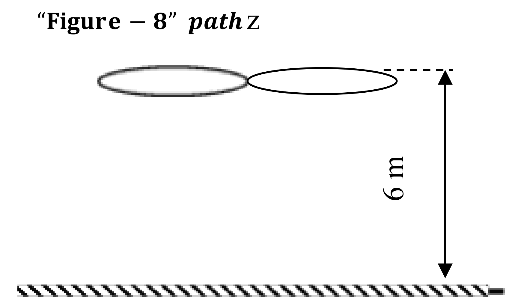
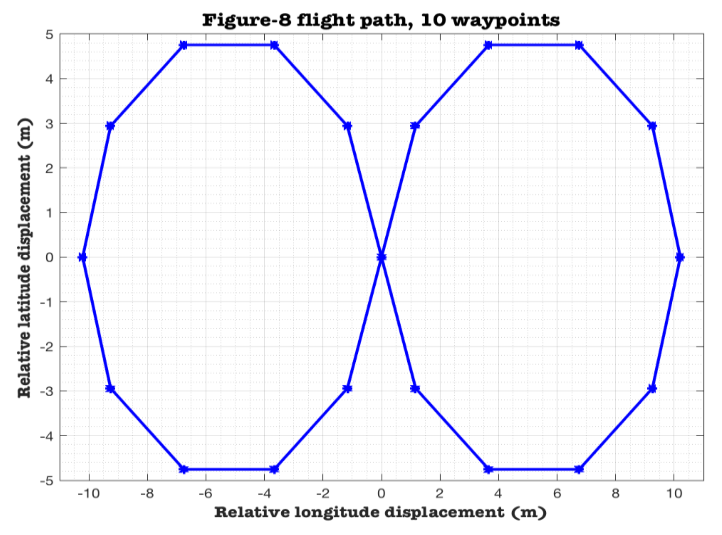
This article describes data from autonomous flights of a custom-designed and fabricated Quadcopter, conducted at the AirCRAFT Laboratory, Parks College of Engineering, Aviation and Technology, Saint Louis University, St. Louis, MO, USA. The Quadcopter was programmed to fly a pre-defined “Figure-8” flight path, at a constant altitude, as illustrated in Figure 1 and Figure 2.
The Data Files included with this article describe flights with a varying number of waypoints (10 and 15 waypoints in each lobe of the “Figure-8”) and at two different velocities (1.5 and 2.5 m/s). Table 1 lists the flight variables available in the datasets.
Additional channels of data exist in the data set. Interested researchers could refer to the Pixhawk reference [8] for more details.
3. Methods
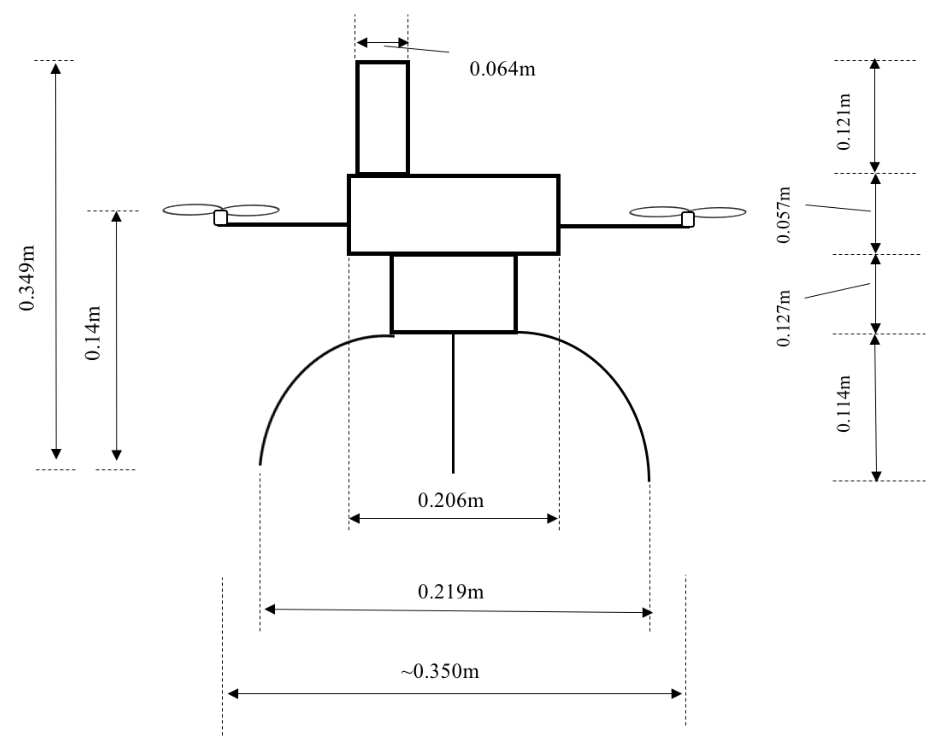
As described earlier, this data set contains flight data from a series of experimental flight tests conducted using a custom-designed quadcopter at the AirCRAFT Laboratory [9], Parks College of Engineering, Aviation and Technology at Saint Louis University, St. Louis, MO, USA. The quadcopter and its physical dimensions are shown in Figure 3 and Figure 4, respectively. It is approximately in the 350-mm class and features an additively manufactured central hub and carbon fiber arms. Additional details of the quadcopter frame are given in the following paragraph.
a. Flight controller
For these experiments, the Pixhawk flight controller, which is a high-performance autopilot-on-module, was chosen as the quadcopter’s flight controller. It is an open-source autopilot system for hobby and academic use. Its low cost, availability and widespread use make it ideal for use in this research effort. The Pixhawk flight controller features a comprehensive suite of sensors required to achieve basic flight. This includes an Invensense MPU 6000 IMU (Inertial Measurement Unit), with accelerometers, gyroscopes, and magnetometers to measure body axis angular rates and translational acceleration. The magnetometer measures the earth’s magnetic field and is used to determine the orientation of the quadcopter relative to the earth-fixed reference frame. It also features a barometer to determine the altitude of the quadcopter. A subset of the specifications are listed in Table 2 below.
b. Motor and ESC (Electronic Speed Controller)
The quadcopter is powered by a set of four KDA 20-22 L brushless outrunner motors, through four Plush 18 A ESCs and a power distribution board. A subset of the specifications of the motor and speed controllers is given in Table 3 below.
c. Flight Tests
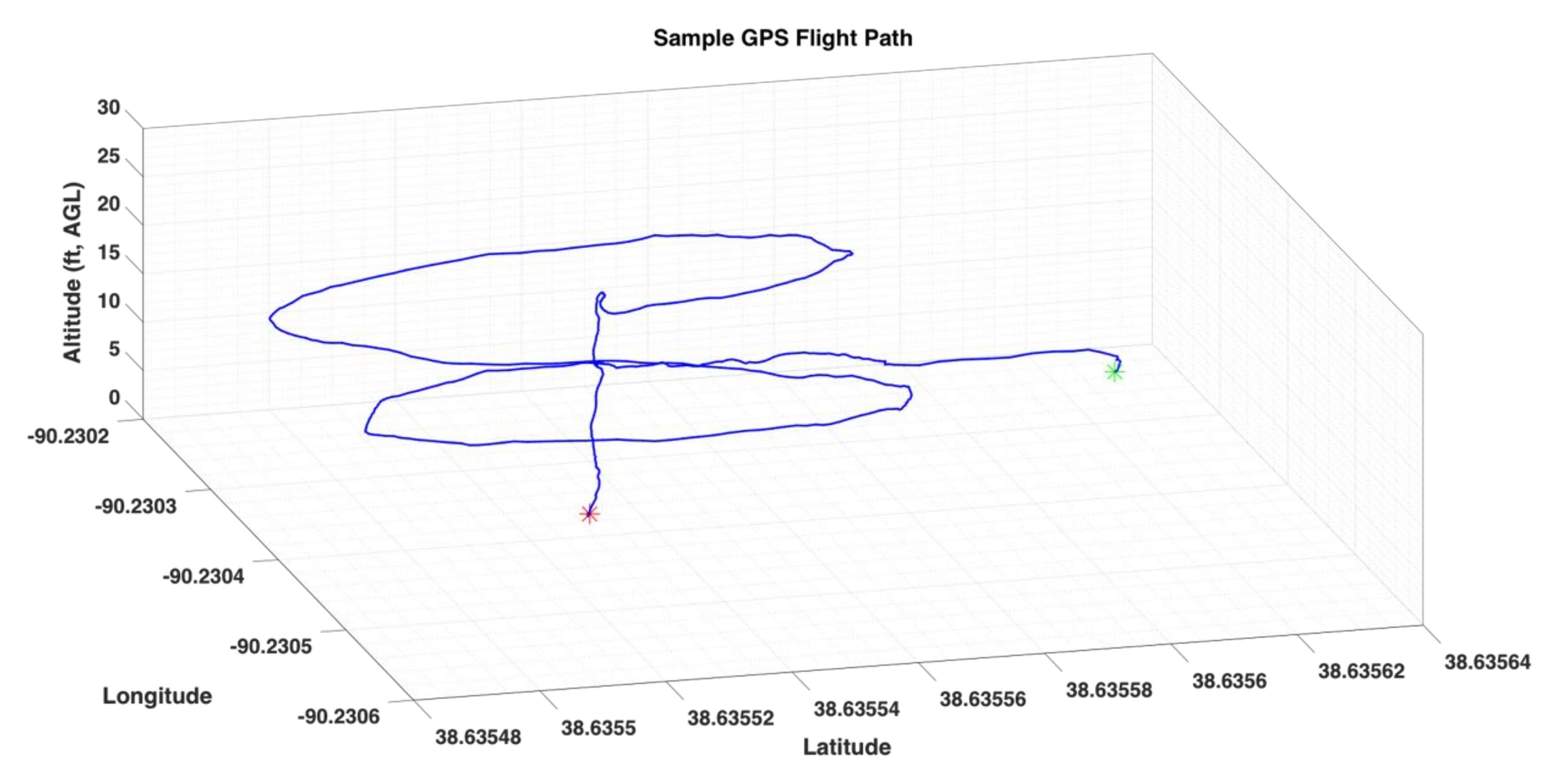
In the experiments, the quadcopter is programmed to fly multiple waypoints in a Figure-8 pattern. Takeoffs are typically handled by a ground pilot to ensure safety, prior to executing autonomous flight, which is achieved by a control switch on the Remote Control (RC) transmitter. To ensure that the experiments are reasonably repeatable, once it is switched to autonomous mode, the quadcopter is designed to fly to the center of the Figure-8 pattern and to hover for 5 s, prior to executing the flight pattern. This allows for stabilization of the quadcopter’s attitude, translational/angular velocity, and acceleration to zero. This procedure is repeated at the end of the flight, after flying the pattern, the quadcopter returns to its center point and hovers for 5 s, before initiating the landing sequence. The ground pilot always maintains override authority during autonomous flight; in case of emergencies, the pilot recovers control of the quadcopter to bring it back to safety. A sample flight is shown in Figure 5 below.
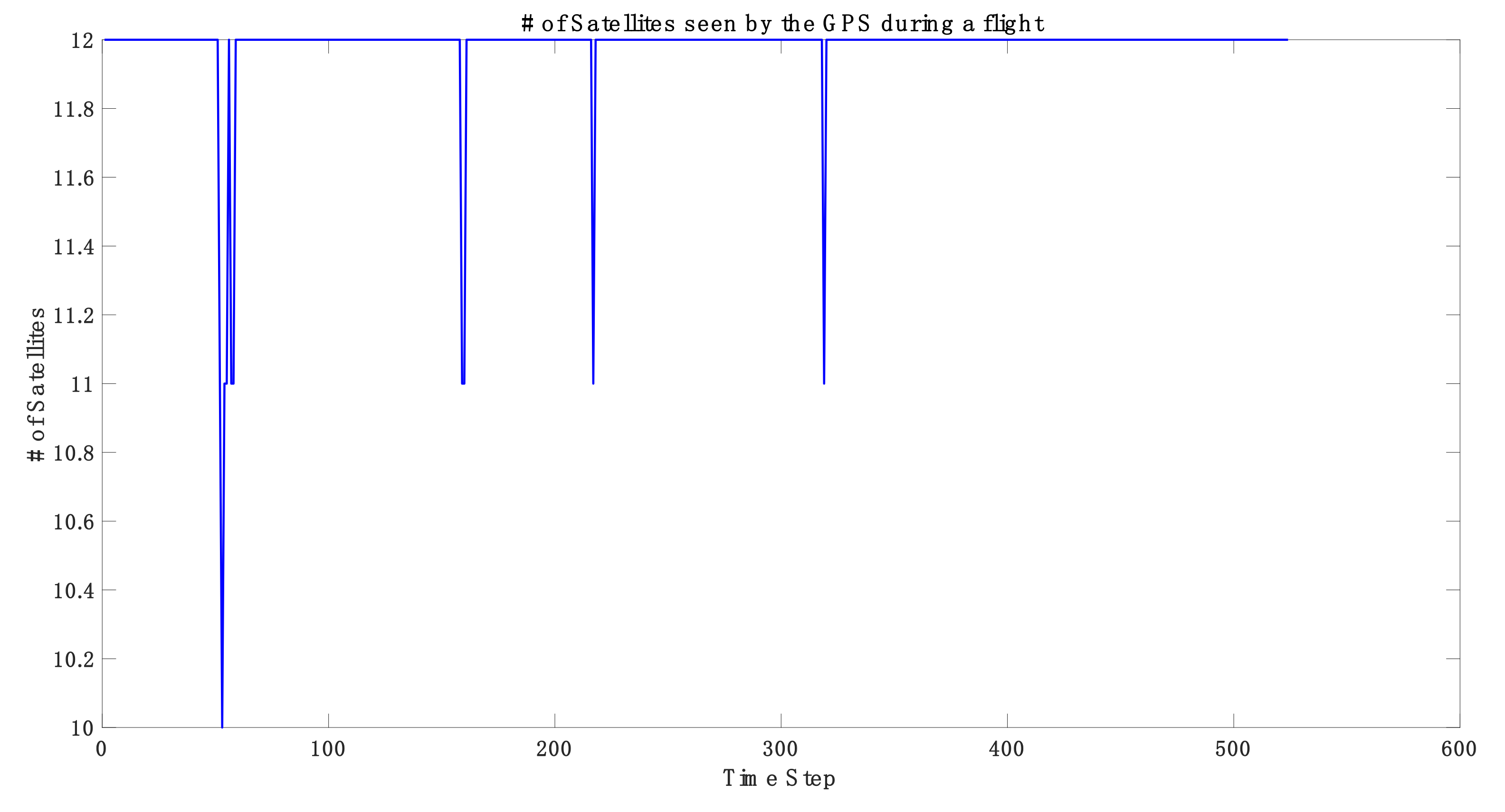
For the above flight, the corresponding GPS coverage is shown below in Figure 6, in terms of the number of satellites seen by the GPS unit mounted on the quadcopter. This information is stored in the ‘GPS’ data variable.
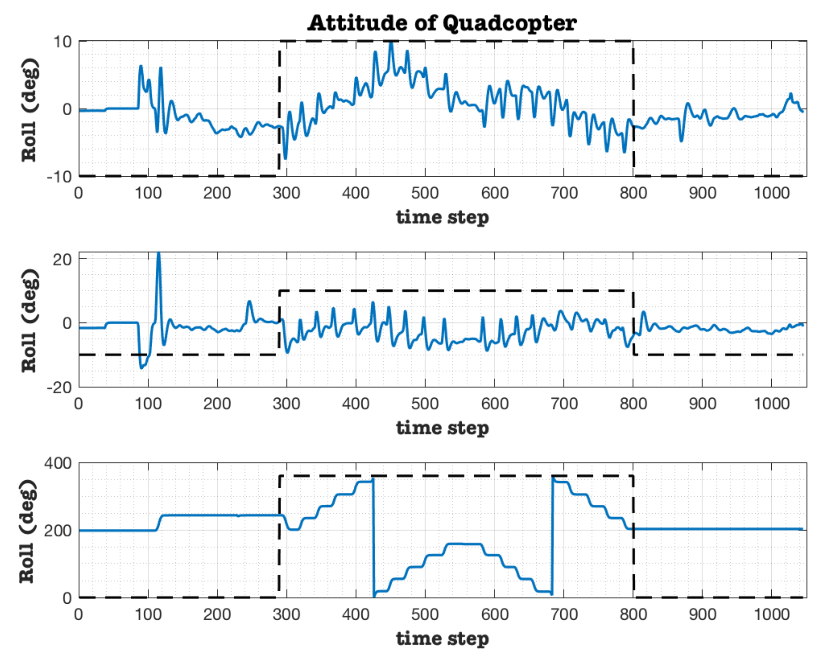
The corresponding attitudes of the quadcopter for the flight shown in Figure 5 are shown below in Figure 7. The flight segment between the center of the “Figure-8” pattern and before the 5s hover maneuver prior to landing is marked by the dashed black line in Figure 7.
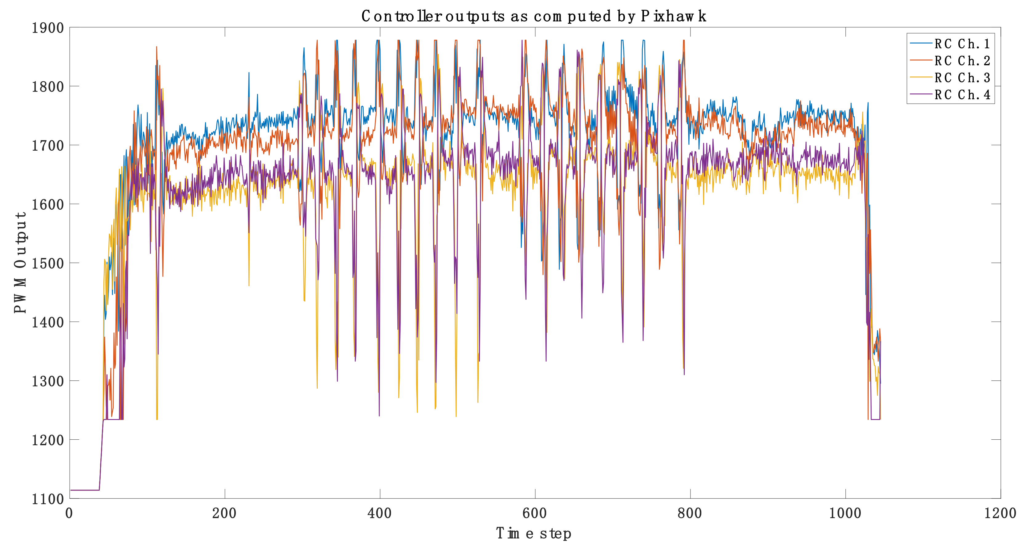
Finally, the RC outputs from the flight controller for the same flight are shown below in Figure 8. The RC outputs correspond to the output of the flight controller, in order to maintain desired attitudes and execute the “Figure-8” flight path, autonomously.
4. User Notes
Users need to note that the data stored in various variables are sampled at different frequencies. It would be useful to resample the data to a baseline frequency to enable analysis of the data. Except the IMU (inertial measurement unit), the sample frequency of most other sensors is 10 Hz, and the GPS sensor is 5 Hz. For instance, we have resampled data from all other sensors to match the sampling frequency of the IMU, which is 25 Hz. This information is summarized in Table 4 below:
Supplementary Materials
Supplementary materials can be found at https://0-www-mdpi-com.brum.beds.ac.uk/2306-5729/4/1/39/s1. Data files: The files contain data from flight tests of a custom designed quadcopter, autonomously flying a figure-8 pattern, at a constant altitude.
Author Contributions
Conceptualization, S.G.; methodology, S.G.; Experiments, Y.B., resources, S.G.; data curation, S.G., Y.B.; writing—original draft preparation, S.G.; writing—review and editing, S.G.; visualization, S.G., Y.B.; supervision, S.G.; project administration, S.G.; funding acquisition, S.G.
Funding
This research received no external funding.
Acknowledgments
We would like to acknowledge members of the AirCRAFT Laboratory for their support during the experimental flights.
Conflicts of Interest
The authors declare no conflict of interest.
References
- FAA sUAS Part 107: The Small UAS Rule. Available online: https://www.faa.gov/uas/media/Part_107_Summary.pdf (accessed on 7 March 2019).
- Sun, Z.; Zhang, Y. Using Drones and 3D Modeling to Survey Tibetan Architectural Heritage: A Case Study with the Multi-Door Stupa. Sustainability 2018, 10, 7. [Google Scholar] [CrossRef]
- Molina, P.; Colomina, I.; Victoria, P.; Skaloud, J.; Kornus, W.; Prades, R.; Aguilera, C. Drones to the Rescue! Inside GNSS; July/August 2012. Available online: http://infoscience.epfl.ch/record/180464 (accessed on 7 March 2019).
- Câmara, D. Cavalry to the rescue: Drones fleet to help rescuers operations over disasters scenarios. In Proceedings of the 2014 IEEE Conference on Antenna Measurements & Applications (CAMA), Antibes Juan-les-Pins, France, 16–19 November 2014; pp. 1–4. [Google Scholar]
- Silvagni, M.; Tonoli, A.; Zenerino, E.; Chiaberge, M. Multipurpose UAV for search and rescue operations in mountain avalanche events. Geomat. Nat. Hazards Risk 2017, 8, 18–33. [Google Scholar] [CrossRef]
- Bai, Y. Control and Simulation of Morphing Quadcopter. Master’s Thesis, Parks College of Engineering, Aviation and Technology, Saint Louis University, St. Louis, MO, USA, December 2017. [Google Scholar]
- EKF2 Estimation System, Learning the ArduPilot Codebase. Available online: http://ardupilot.org/dev/docs/ekf2-estimation-system.html (accessed on 7 March 2019).
- Pixhawk 1 Flight Controller. Available online: https://docs.px4.io/en/flight_controller/pixhawk.html#specifications (accessed on 7 March 2019).
- AirCRAFT Laboratory. Aircraft Computational & Resource Aware Fault Tolerance (AirCRAFT) Lab; Parks College of Engineering, Aviation and Technology, Saint Louis University: St. Louis, MO, USA; Available online: https://sites.google.com/a/slu.edu/aircraft-lab/ (accessed on 7 March 2019).
Figure 1.
Side profile of autonomous flight path.

Figure 2.
A sample “Figure-8” flight path.

Figure 3.
The custom-built quadcopter used in the experiments.

Figure 4.
Physical dimensions of the quadcopter.

Figure 5.
Sample flight path of quadcopter. Note: Green: Start; Red: End.

Figure 6.
GPS coverage corresponding to the flight data shown in Figure 5.
Figure 6.
GPS coverage corresponding to the flight data shown in Figure 5.

Figure 7.
Attitude of the quadcopter corresponding to the flight data shown in Figure 5.
Figure 7.
Attitude of the quadcopter corresponding to the flight data shown in Figure 5.

Figure 8.
Controller outputs as computed by Pixhawk controller, corresponding to the flight shown in Figure 5.
Figure 8.
Controller outputs as computed by Pixhawk controller, corresponding to the flight shown in Figure 5.


Table 1.
Description of data channels in experimental data sets.
| Variable | Descriptor (Variable Label) | Channels | Notes |
|---|---|---|---|
| AHR2 | AHR2_label | Roll, Pitch, Yaw, Alt, Lat, Lng | |
| ATT | ATT_label | DesRoll, Roll, DesPitch, Pitch, DesYaw, Yaw, ErrRP, ErrYaw, | |
| BARO | BARO_label | Alt, Press, Temp, CRt, SMS, Offset | |
| CMD | CMD_label | CTot, CNum, CId, Prm1, Prm2, Prm3, Prm4, Lat, Lng, Alt | This contains the waypoints that were commanded in the “Lat”, “Lng” and “Alt” channels |
| CTUN | CTUN_label | ThI, ABst, ThO, ThH, DAlt, Alt, BAlt, DSAlt, SAlt, TAlt, DCRt, CRt | Control, Throttle, and altitude information |
| CURR | CURR_label | Volt, Curr, CurrTot | |
| GPA | GPA_label | VDop, HAcc, VAcc, SAcc, VV, SMS | This contains the Vertical Dilution of Precision (VDOP) parameter |
| GPS | GPS_label | Status, GMS, GWk, NSats, HDop, Lat, Lng, Alt, Spd, GCrs, VZ, U | This contains the Horizontal Dilution of Precision (HDOP) parameter |
| IMU, IMU2 | IMU_label, IMU2_label | GyrX, GyrY, GyrZ, AccX, AccY, AccZ, ErrG, ErrA, Temp, GyHlt, AcHlt | Body axis angular rates () and accelerations () |
| MAG, MAG2 | MAG_label, MAG2_label | MagX, MagY, MagZ, OfsX, OfsY, OfsZ, MOfsX, MOfsY, MOfsZ, Health, S | |
| NKF1- NKF9 | NKF1_label–NKF9_label | Roll, Pitch, Yaw, VN, VE, VD, dPD, PN, PE, PD, GX, GY, GZ | More details can be found in [7] |
| PM | PM_label | NLon, NLoop, MaxT, PMT, I2CErr, INSErr, LogDrop | Performance Monitoring |
| POS | POS_label | Lat, Lng, Alt, RelAlt | Position Log |
| RCIN | RCIN_label | RC Inputs, Channels 1–16 | Channel 5 represents the switch to autonomous flight |
| RCOU | RCOU_label | Output of the flight controller | Channels 1–4 are the outputs of the flight controller, fed to the four speed controllers controlling the motors |
Table 2.
Pixhawk flight controller specifications.
 3DR Pixhawk Flight Controller | Central Processign Unit (CPU) | 168 MHz Cortex-M4F |
| Input/Output | 14 PWM/Servo outputs | |
| Extra connectivity | UART, I2C, GPS | |
| Power distribution | Redundant power supplies | |
| Flight log | Pluggable microSD card | |
| Inertial Measurement Unit (IMU) | Invensense MPU6000 (ST Micro 3-axis 14 bit accelerometer, 3-axis, 16 bit gyro) | |
| GPS | 3DR GPS module |
Table 3.
Specifications of Motor and electronic speed controller (ESC).
| Motor | ESC | ||
 KDA 20-22 L Brushless Outrunner Motor. |  Plush 18 A ESC. | ||
| Kv | 924 | Burst Current | 22 A |
| Operating Current | 6–14 A | Constant Current | 18 A |
| Max. Voltage | 11 v | BEC | 5 v/2 A; Linear |
| Size/Weight | 28 × 32 mm; 56 g | LiPo | 2–4 cells |
| Size/Weight | 24 × 45 × 11 mm/19 g | ||
Table 4.
Sample rates of different sensors.
| Sensor | Original Sample Frequency | Resampled Frequency |
|---|---|---|
| ATT (Attitude) | 10 Hz | 25 Hz |
| CTUN (Altitude) | 10 Hz | 25 Hz |
| Curr (Current and Voltage) | 10 Hz | 25 Hz |
| IMU | 25 Hz | 25 Hz |
| IMU2 | 25 Hz | 25 Hz |
| NTUN (Velocity) | 10 Hz | 25 Hz |
| POS (Position, filtered from GPS) | 10 Hz | 25 Hz |
| RCOU (Controller output) | 10 Hz | 25 Hz |
| GPS | 5 Hz | 25 Hz |
© 2019 by the authors. Licensee MDPI, Basel, Switzerland. This article is an open access article distributed under the terms and conditions of the Creative Commons Attribution (CC BY) license (http://creativecommons.org/licenses/by/4.0/).
Share and Cite
MDPI and ACS Style
Gururajan, S.; Bai, Y. Autonomous “Figure-8” Flights of a Quadcopter: Experimental Datasets. Data 2019, 4, 39. https://0-doi-org.brum.beds.ac.uk/10.3390/data4010039
AMA Style
Gururajan S, Bai Y. Autonomous “Figure-8” Flights of a Quadcopter: Experimental Datasets. Data. 2019; 4(1):39. https://0-doi-org.brum.beds.ac.uk/10.3390/data4010039
Chicago/Turabian StyleGururajan, Srikanth, and Ye Bai. 2019. "Autonomous “Figure-8” Flights of a Quadcopter: Experimental Datasets" Data 4, no. 1: 39. https://0-doi-org.brum.beds.ac.uk/10.3390/data4010039