The Integration of Vacuum Insulated Glass in Unitized Façade for the Development of Innovative Lightweight and Highly Insulating Energy Efficient Building Envelope—The Results of Eensulate Façade System Design


Abstract
:1. Introduction
2. Materials and Methods
2.1. Eensulate Materials
- Eensulate VIG:
- ○
- Technical characteristics—two panes of 6 mm thick fully tempered glass using a combination of uncoated and soft low-E coated glass. Based on modelling results, an array of stainless-steel support pillars, 0.4 mm in diameter, 0.2 mm high, and spaced on a 50 mm regular grid, maintains the separation of the glass panes. The target expected by the project is a U-value of 0.3 W/sqm∙K at the ultimate vacuum pressure after evacuation of 5e-6 mbar, with a guaranteed lifetime of 20 years through a vacuum level lower than 1e-3mbar. The result achieved in a small scale prototype (500 × 500 mm) is a center-of-pane U-value of 0.36 W/sqm∙K and an overall U-value of 0.44 W/sqm∙K. As the test is already ongoing, the reference for the simulation is a U-value of 0.3 W/sqm∙K.
- ○
- Sealant dimension—the sealant (innovative component of Eensulate’s VIG) guarantees the adhesion between the glass panes, but it is a thermal bridge to be considered. Its dimension has changed during VIG development from 15 to 25 mm, affecting the Eensulate façade system design.
- ○
- Sealant and getter position—their dimension (sealant is 15–25 mm and getter is a strip of 8 mm) and their position in the VIG are aesthetic issues to be faced to guarantee architectural appraisal of the Eensulate façade.
- ○
- Pumping hole position—necessary to pump out the air during vacuum creation; its position is an aesthetic issue to be faced.
- ○
- Laminated glass—a lamination is needed for safe installation of the façade and to avoid falling risk in case of glass breakage. For this purpose, an additional pane of 6 mm of Heat Strengthened (HS) glass has been included.
- Eensulate foam:
- ○
- Technical characteristics—Two Component Foam (TCF) is highly insulating polyisocyanurate (PIR) foam-based insulating material enhanced with eco-friendly lamellar inorganic fillers. TCF is used to be injected and is workable for manufacturing. The advantages of the TCF system during the production system are the increased efficiency of 35 kg/cm and ease of processing. The U-value is 0.024 W/sqm∙K.
2.2. Methods
- Identification of preliminary boundary conditions:
- Preliminary design solution—starting from preliminary design outputs set as in the early phase of the project, the Eensulate façade system design was implemented with the information and results during VIG and foam development. The preliminary design defined a U-value target for the unit with an Eensulate façade module dimension of 1500 × 3500 mm as 0.586 W/sqm∙K for VIG with 15 mm of sealant (thermal bridge) and using structural silicone, and as 0.641 W/sqm∙K for VIG with 25 mm.
- Market benchmark—identification of components, especially profiles, to be used in the Eensulate module. In addition, the identification of the current façade market benchmark with a similar U-value to the Eensulate façade module has been investigated.
- Safety issue—despite all the necessary solutions having been adopted to guarantee a safety installation of VIG, the behavior of the VIG under stress conditions needs further investigation. For this reason, the Eensulate façade system has not been designed for structural silicone as expected in preliminary design activities, but with a glazing bead for VIG restraint that has been introduced, causing an additional thermal bridge in the module that affects the thermal behavior of the whole Eensulate façade system. The consequence is an improvement of the thermal bridge, an issue to be faced during the design phase.
- Eensulate module design and optimization:
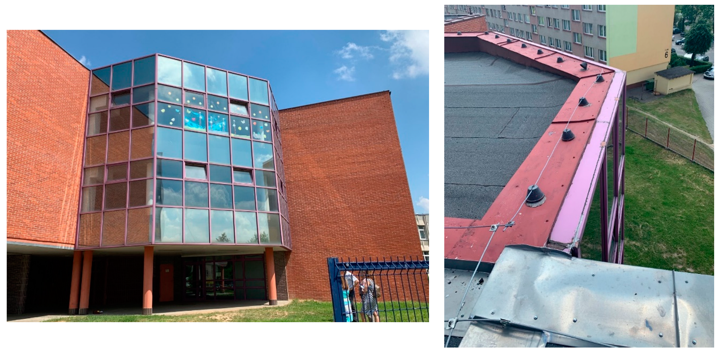
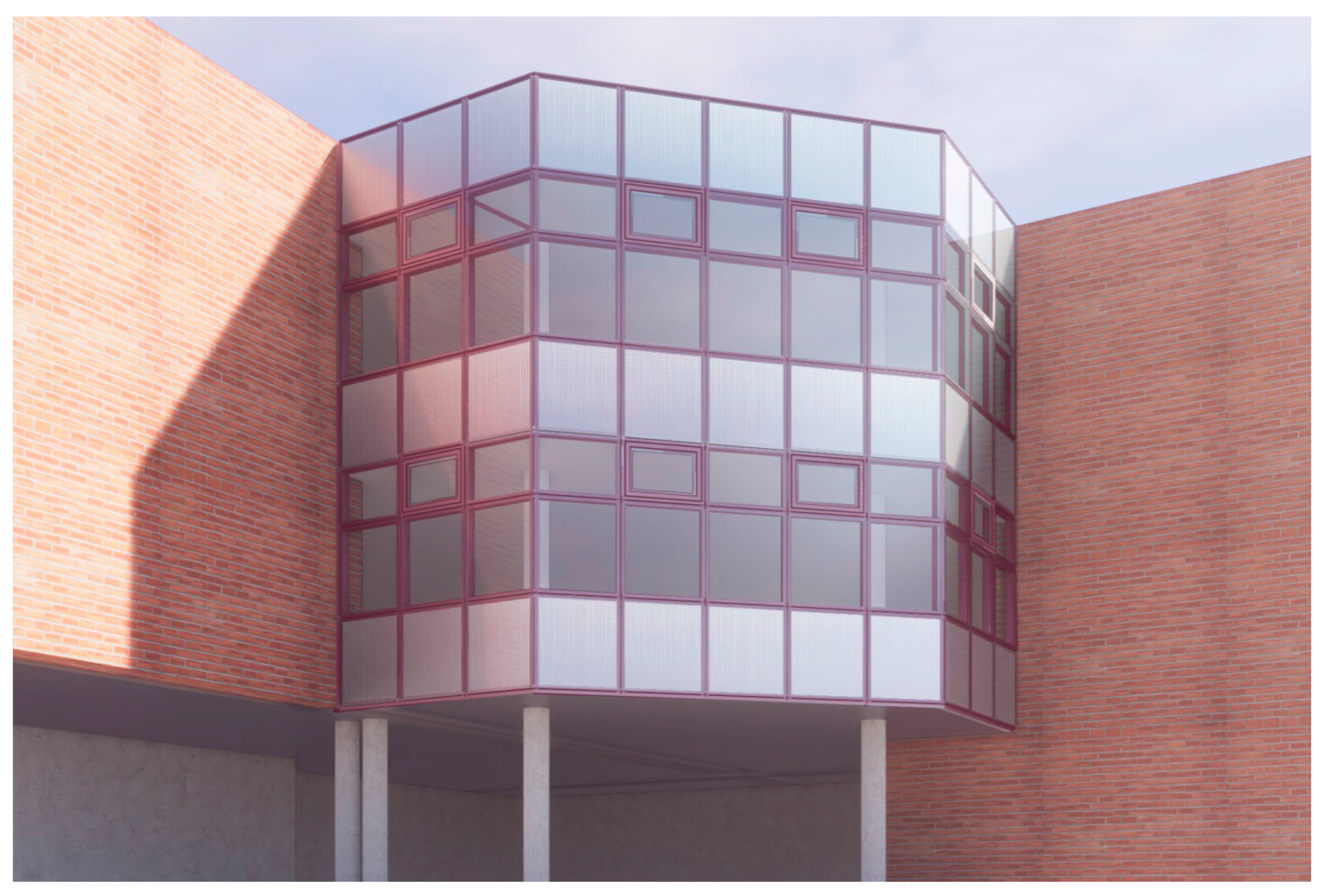
- Façade engineering design—the U-value expected by the project was defined for a façade unit of 1500 × 3500 mm. However, the building demonstrator to validate the Eensulate façade in a real environment is a school in Dzierżoniów, Poland (Figure 1), which has been used to size the unit of reference. The school built in the 1980s has a façade object of intervention in the Eensulate project of 90 sqm, realized with a stick system with an estimated U-value > 3.5 W/sqm∙K. On the base of the existing school’s façade, the unit dimension considered as the reference (the school in Dzierżoniów, Poland) is 1261 × 3640 mm (Figure 2); this dimension has been considered the reference to achieve the U-value target for real dimensions. As the aluminum profile’s U-value is worse than the VIG’s U-value, this choice is more negative to pursue the planned target because the U-value of VIG (lower than the aluminum profile) has a lower incidence. Additionally, the key elements to be considered and balanced in façade engineering are:
- i.
- Thermal performances—from 0.586 W/sqm∙K (sealant 15 mm) to 0.7 W/sqm∙K (sealant 25 mm) is the target of the project.
- ii.
- Performances of the façade—compliance with UNI EN 13830:2005 to obtain CE on the façade.
- iii.
- Acoustic performance—52 dB of insulation.
- iv.
- Replacement strategy—in case of VIG failure because of shorter durability in relation to the planned lifespan expectation of 20 years.
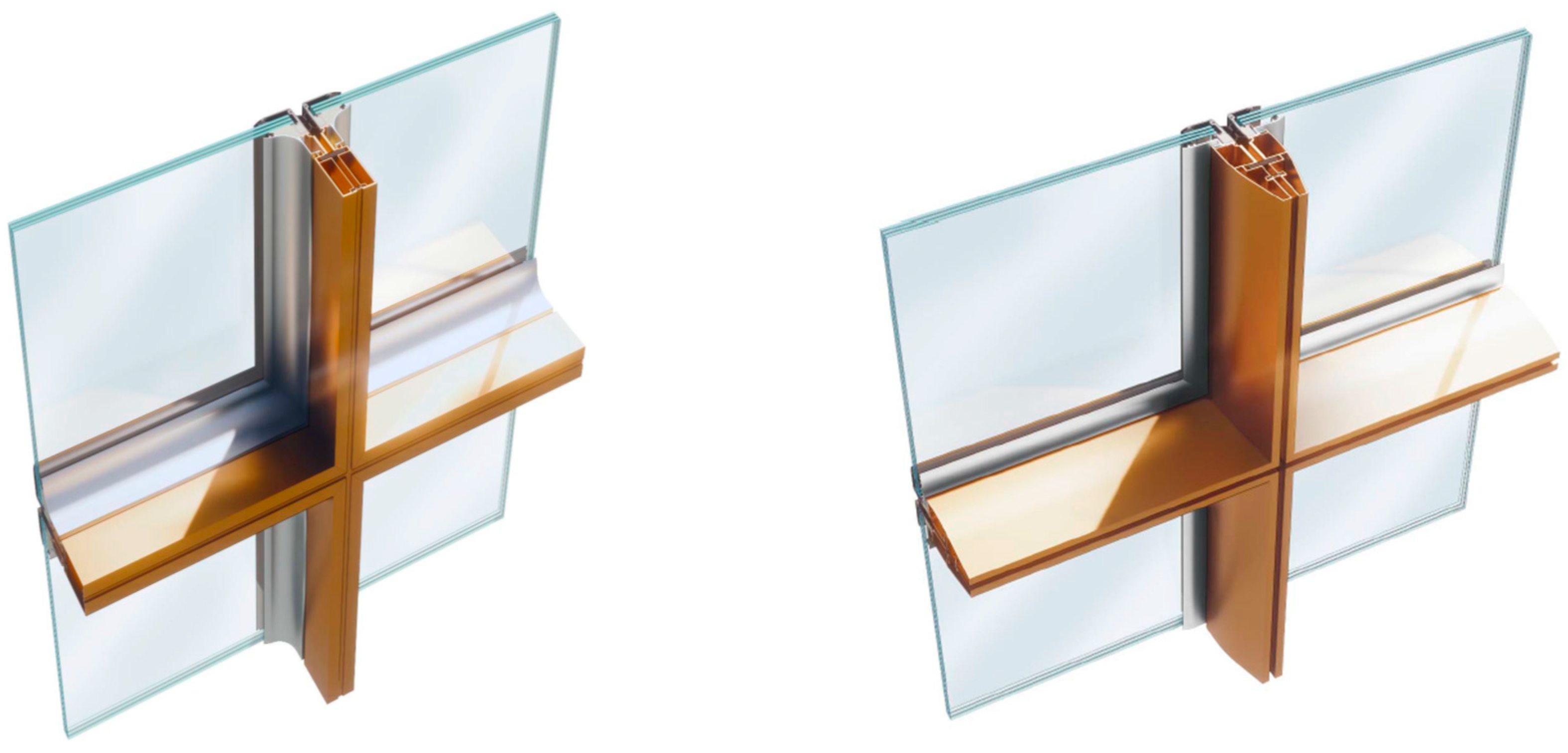
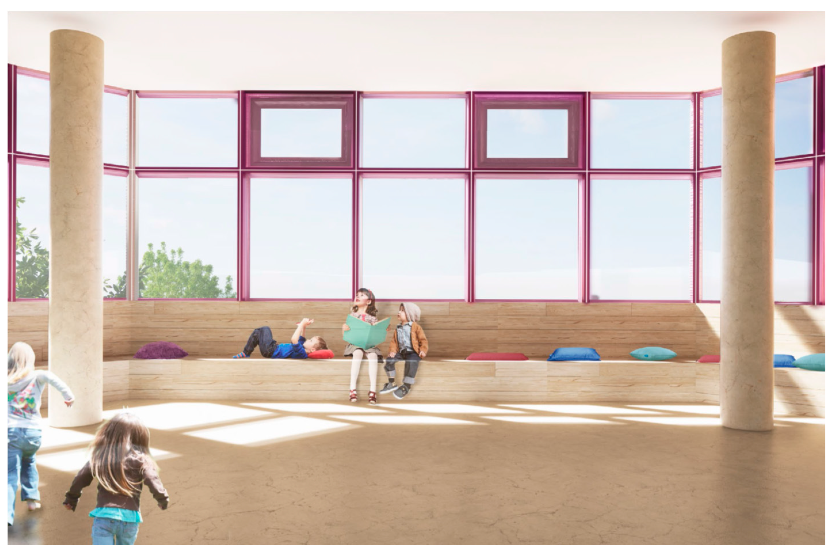
- Façade architectural design—requests emerged from the architect and building demonstrator owner to balance the aesthetical appraisal of the Eensulate module and homogenize the façade with already existing solutions in the building (glazing beads and colors in the current façade configuration, Figure 3 and Figure 4).
- Identification of pitfalls:
- Scalability—design and prototyping direct the identification of the eventual pitfalls necessary to support the scale up of the Eensulate façade’s components for their application in the façade system.
- Industrialization—design and prototyping direct the identification of the eventual pitfalls to industrialize the Eensulate façade supporting massive use and wide replication.
- ●
- Thermal properties of the materials;
- ●
- Cold-side environmental temperature;
- ●
- Cold-side surfaces thermal resistance;
- ●
- Warm-side environmental temperature;
- ●
- Warm-side surfaces thermal resistance.
- UTJ thermal transmittance of thermal joint (node), in W/sqm∙K;
- ΦTJ heat flow rate of thermal joint, in W/m;
- UFE thermal transmittance of filling element (glazing, spandrel), in W/sqm∙K;
- ATJ projected area of thermal joint, in m;
- AFE projected area of filling element, in m;
- ΦTOT total heat flow rate of section, in W/m.
3. Results
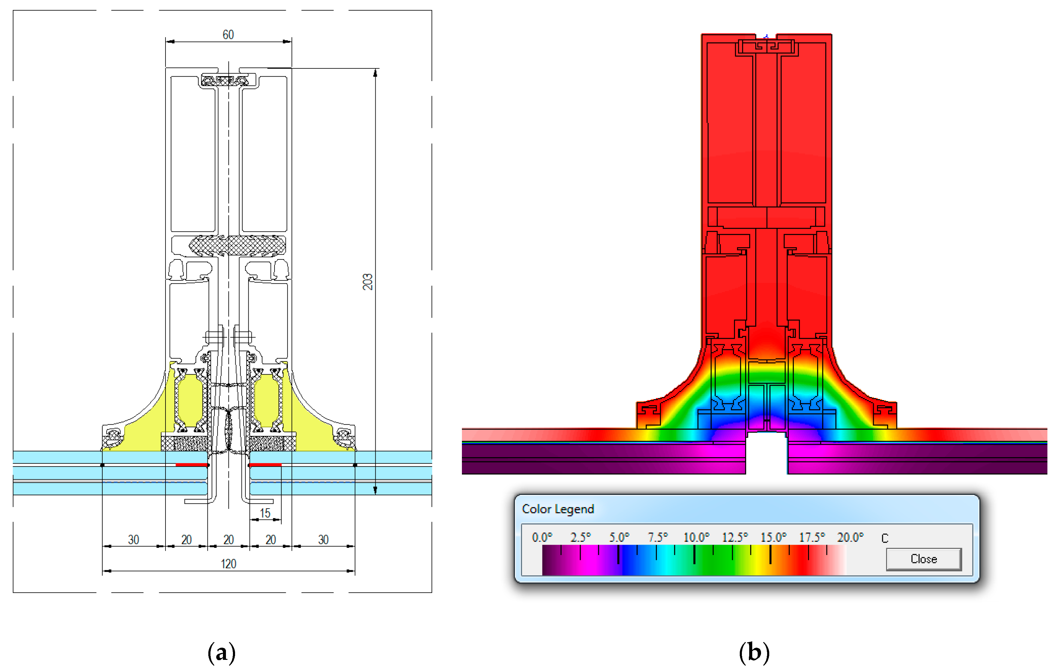
3.1. Eensulate Facade System: 1st Solution
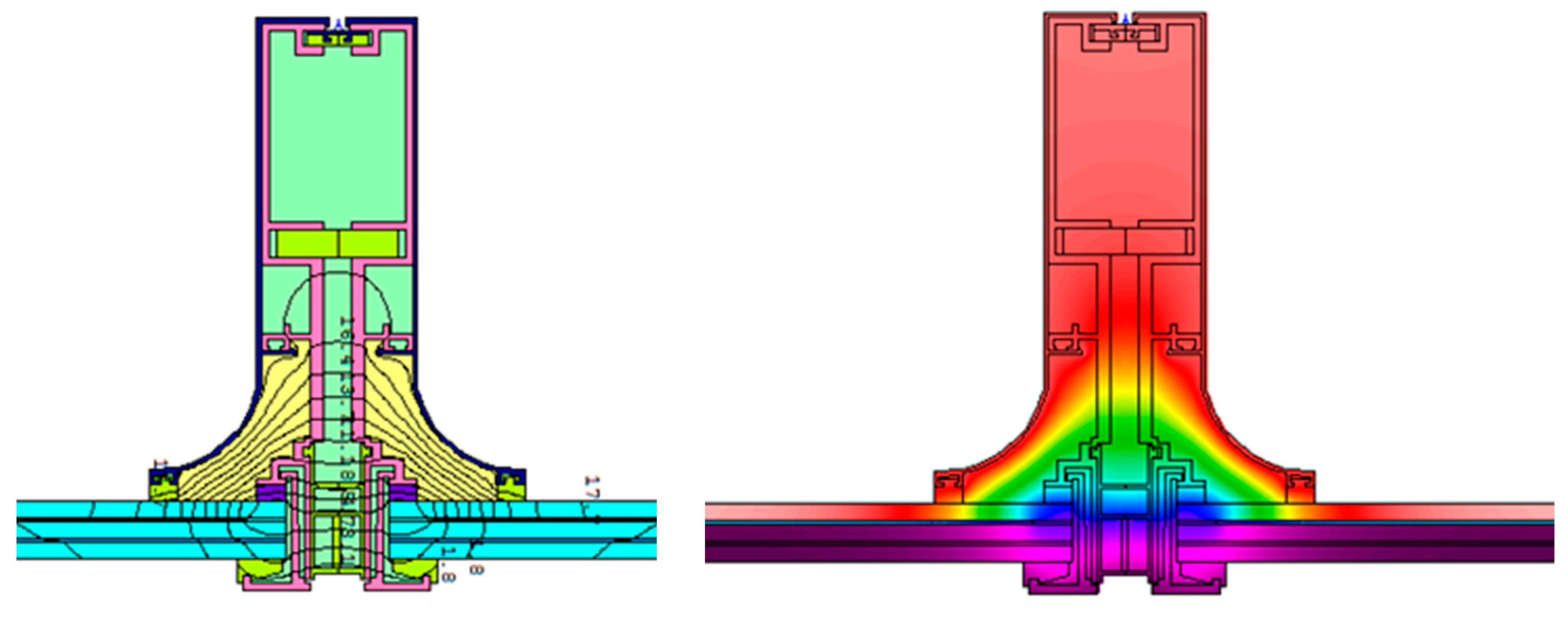
3.2. Eensulate Facade System: 2nd Solution
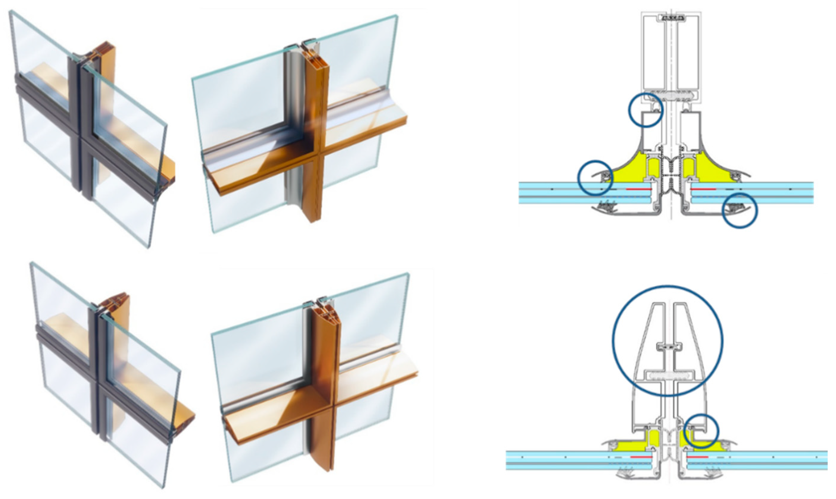
3.3. Eensulate Facade System: 3rd Solution
3.4. Eensulate Façade System Optimization
3.4.1. Investigation of Pultruded Profiles
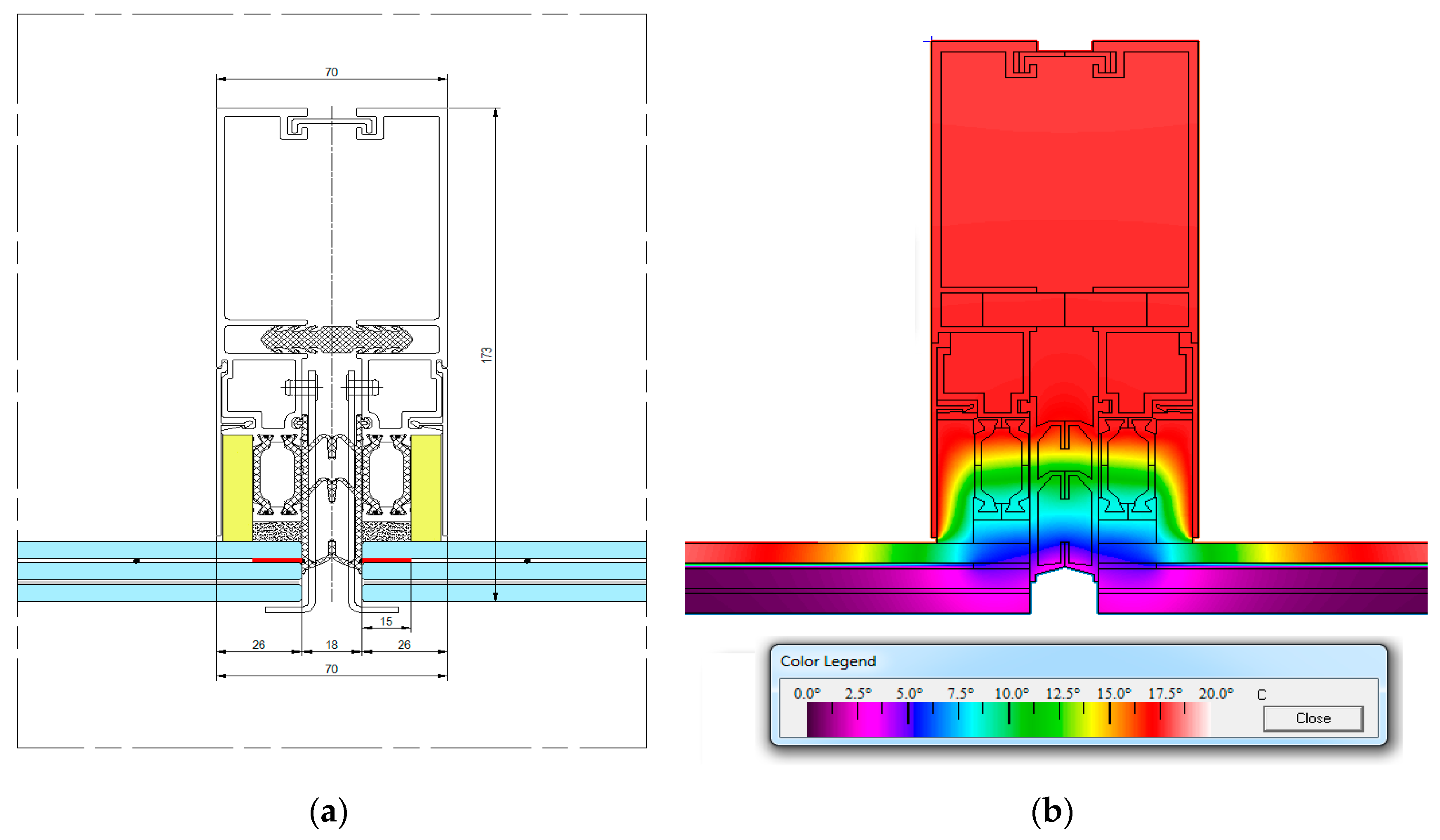
- Eensulate façade system—pultruded 1–25 mm sealant, pultruded profile, aluminum glazing bead.
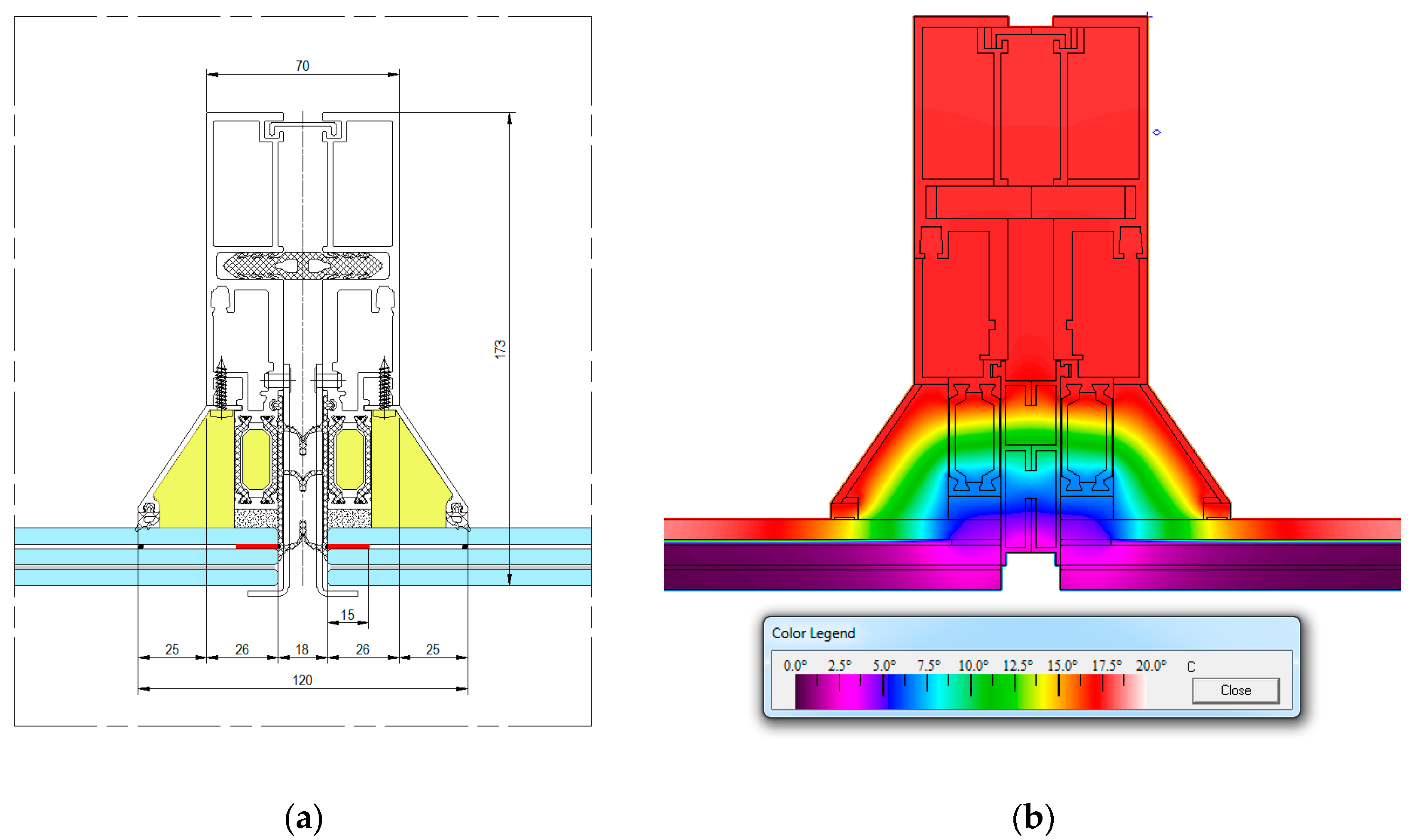
- Eensulate façade system—pultruded 2–25 mm sealant, pultruded profile, pultruded glazing bead (Figure 8).
3.4.2. Architectural and Demo Requirements
3.4.3. Market Benchmark and Replacement Strategy
3.5. Eensulate Facade System: Final Design
VIG Specifications
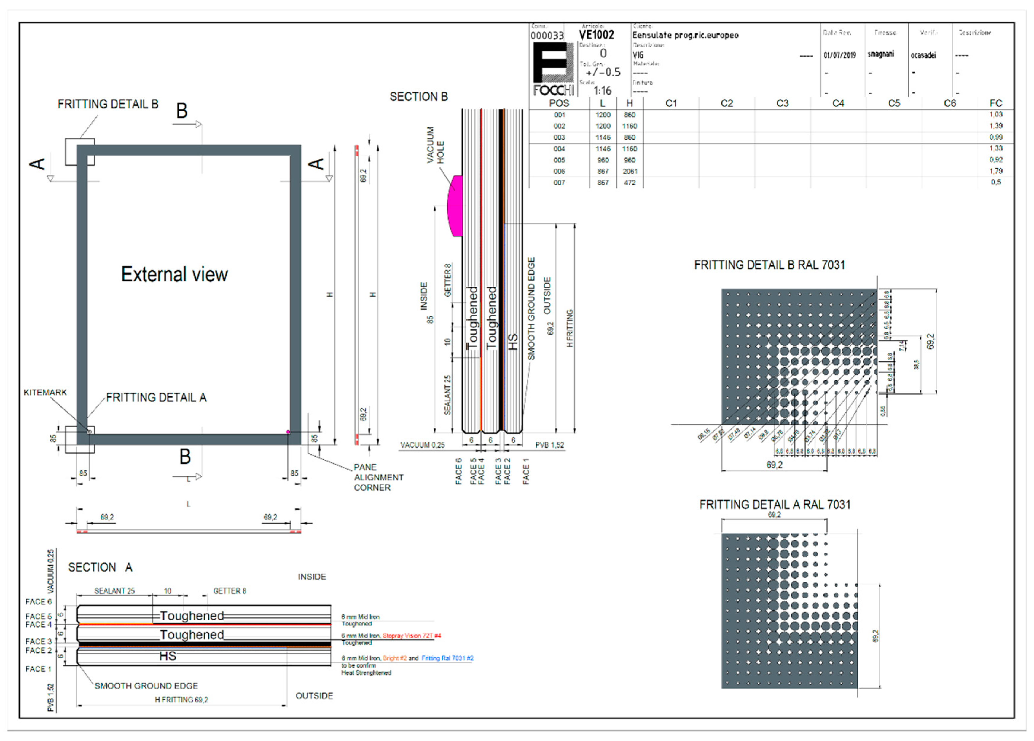
- VIG lamination—the external glass pane is laminated to avoid falling risk in case of VIG breakage, meeting the safety specifications of public buildings;
- Fritted glass—sealant and getter design is a frame all around the VIG of 43 mm total (sealant 25 mm, space between the sealant and getter 10 mm, getter 8 mm) that can have consequences on aesthetic of the glass. In order to minimize the visual effect of this frame, a gradient fritting has been adopted to reduce the visibility of the sealant and getter.
4. Discussion
- Integration of innovative Eensulate components—both Eensulate foam and Eensulate VIG can be integrated in a façade solution. The parallel development of VIG and the Eensulate façade system design has allowed definition of the two products in a win-win strategy: on the one hand, VIG demonstrates its applicability in a unitized system; on the other, the curtain wall system keeps demonstrating the capability to integrate multiple components thanks to its prefabricated and high precise design.
- High energy efficiency of Eensulate module—the overall U-value of the Eensulate module (1261 × 3640 mm) is 0.64 W/sqm∙K, a significant step in relation to the market benchmark (the Eensulate façade’s U-value with TGU is 0.77 W/sqm∙K) with an estimate improvement of 16.8%.
- New profiles definition—to integrate the VIG, new aluminum profiles with internal insulation and a new polyamide profile for thermal break have been identified.
- Valuable architectural aesthetic—the final aesthetic of the Eensulate module respects the architectural target for the curtain wall façade, allowing the personalization of some details (frame treatment, fritting), with some minor issues but which are architectural acceptable (curved cover-cap, fritting).
5. Conclusions
- Tests—specific tests will be conducted to validate the façade and achieve the façade’s CE certification with UNI EN 13830:2005, acoustic insulation (target is expected to be 52 dB), and fire test in a furnace (in comparison with a benchmark solution).
- Sealant dimension—the sealant is a significant thermal bridge and its dimension is a challenging topic. Sealant dimension reduction is an important step to improve further the thermal transmittance of the façade with an impact on architectural issue binding at this moment (fritting and bright in VIG or curved cover-cap in profile).
Author Contributions
Funding
Conflicts of Interest
References
- European Commission. EUROPE 2020: A Strategy for Smart, Sustainable and Inclusive Growth 2010. Available online: https://eur-lex.europa.eu/legal-content/en/ALL/?uri=CELEX%3A52010DC2020 (accessed on 12 August 2020).
- European Parliament Directive 2010/31/EU of the European Parliament and of the Council of 19 May 2010 on the Energy Performance of Buildings 2018; European Parliament: Brussels, Belgium, 2018.
- Mays, J.C. De Blasio’s ‘Ban’ on Glass and Steel Skyscrapers Isn’t a Ban at All. New York Times, 25 April 2019. [Google Scholar]
- Schoenefeldt, H. Glass Skyscrapers: A Great Environmental Folly That Could Have Been Avoided. Available online: http://theconversation.com/glass-skyscrapers-a-great-environmental-folly-that-could-have-been-avoided-116461 (accessed on 12 August 2020).
- Epstein, S. Everyone Needs to Stop Building Giant Glass Skyscrapers Right Now. Available online: https://www.wired.co.uk/article/stop-building-glass-skyscrapers (accessed on 12 August 2020).
- Building & Industrial. Widest Range of Glass Solutions on the Market. Available online: https://www.agc-glass.eu/en/products/building-industrial (accessed on 12 August 2020).
- Welcome to Interpane! Available online: https://www.interpane.com (accessed on 12 August 2020).
- Saint-Gobain Glass. Available online: https://www.saint-gobain-glass.com/ (accessed on 12 August 2020).
- Glass Manufacturer, Glass Supplier in Europe | Guardian Glass. Available online: https://www.guardianglass.com/eu/en (accessed on 12 August 2020).
- Fineo AGC Yourglass. Available online: https://www.agc-yourglass.com/it/it/brands/fineo (accessed on 12 August 2020).
- Pilkington SpaciaTM. Available online: http://www.pilkington.com/en/global/products/product-categories/thermal-insulation/pilkington-spacia (accessed on 25 January 2018).
- LandVac Tempered Vacuum Insulated Glass-LandGlass. Available online: https://www.landglass.net/LandVac.html (accessed on 12 August 2020).
- AGC Glass Europe. AGC Glass Unlimited. Available online: https://www.agc-yourglass.com/sites/default/files/brochures/original/yg_pocket_2014_fr.pdf (accessed on 1 September 2020).
- AGC Clearsight. Enhance Your View with Anti-Reflective Glass. Available online: https://www.agc-yourglass.com/sites/default/files/brochures/original/Clearsight_EN_LR.pdf (accessed on 1 September 2020).
- Glass, R. Triple Glazing v Double Glazing. Available online: https://www.regencyglass.co.uk/faq-2/triple-glazing-v-double-glazing/ (accessed on 16 September 2020).
- Home | Eensulate.eu. Available online: http://www.eensulate.eu//___possible__unsafe__site__ (accessed on 27 March 2018).
- Progress | Eensulate.eu. Available online: http://www.eensulate.eu/progress (accessed on 13 August 2020).
- UNSTUDIO—Site. Available online: http://www.unstudio.com/en/page/335/homepage (accessed on 13 August 2020).


| Element | Initial | Data |
|---|---|---|
| Outside temperature | Te | 0 °C |
| Outside heat transfer coefficient | he | 25 W/sqm∙C |
| Inside temperature | Ti | +20 °C |
| Inside heat transfer coefficient | hi | 7.69 W/sqm∙C |
| Inside heat transfer coefficient reduced | hir | 5 W/sqm∙C |
| Solutions Adopted | Issues Emerged | Thermal Transmittance Achieved | Target |
|---|---|---|---|
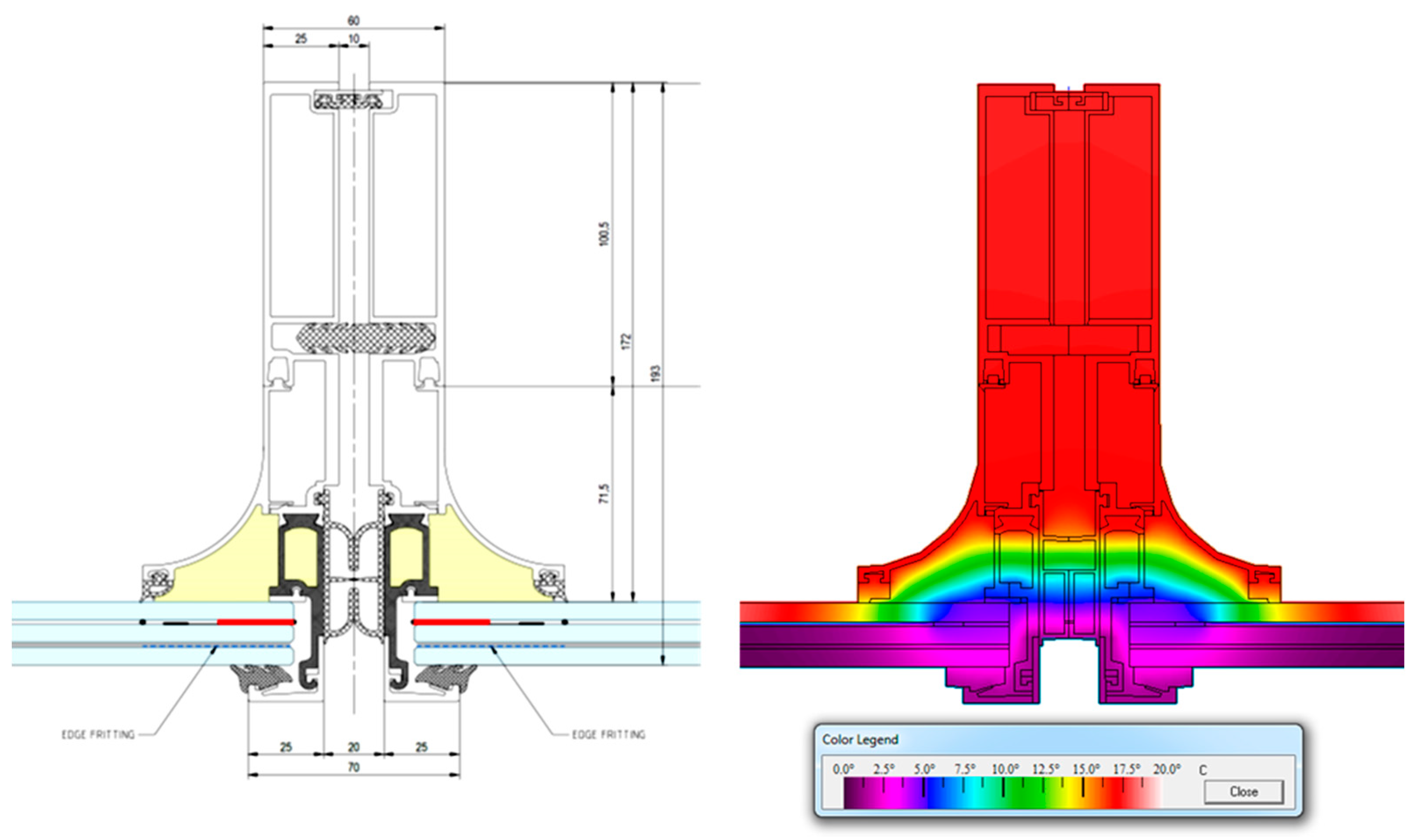
| Sealant 15 mm Insulation in profile (marked in yellow) | Thermal bridge Sealant to 15 mm | 0.79 W/sqm∙K | 0.586 W/sqm∙K (sealant to 15 mm) |
| Solutions Adopted | Issues Emerged | Thermal Transmittance Achieved | Target |
|---|---|---|---|
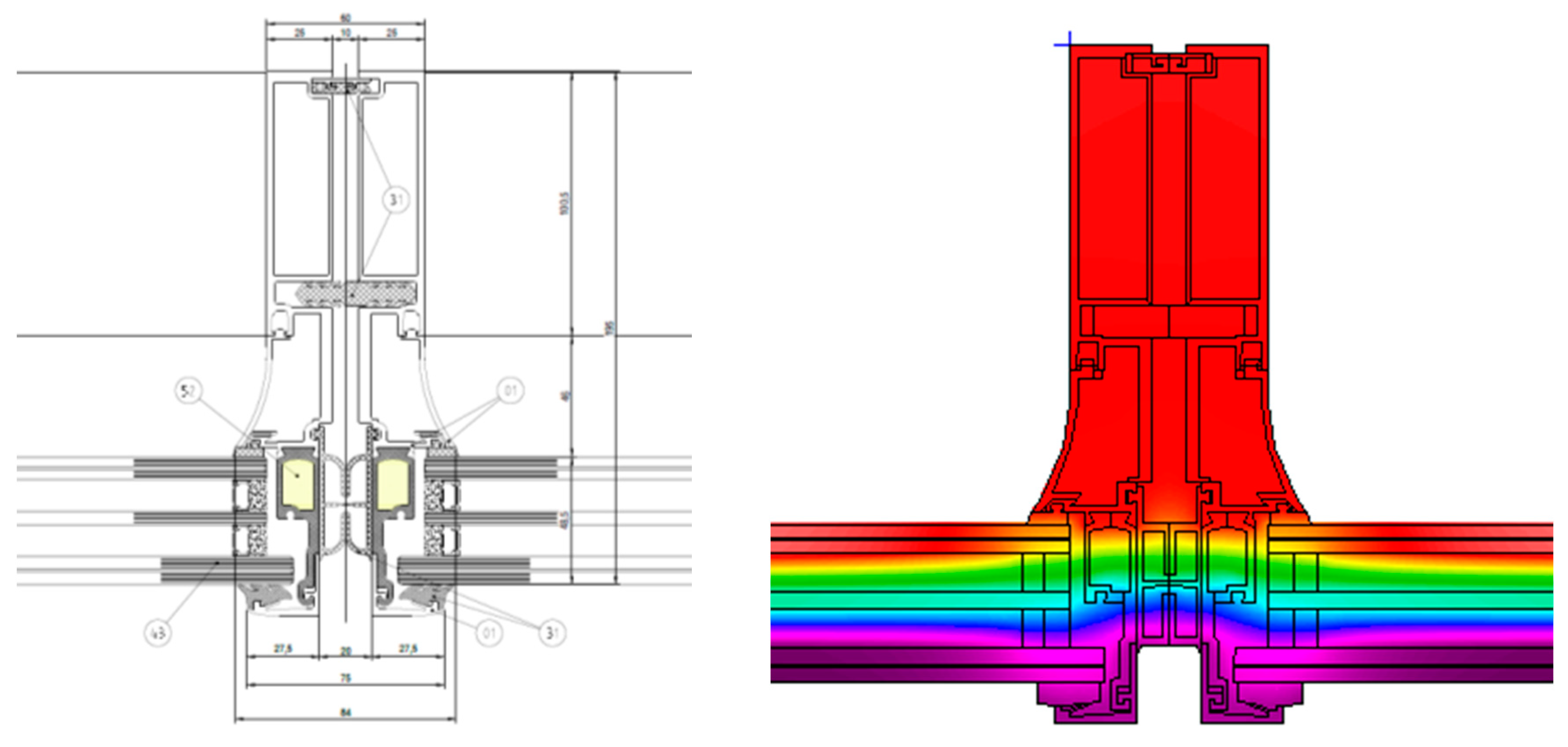
| Profile design for thermal reason | Profile design for aesthetic issue Sealant to 15 mm | 0.58 W/sqm∙K | 0.586 W/sqm∙K (sealant to 15 mm) |
| Solutions Adopted | Issues Emerged | Thermal Transmittance Achieved | Target |
|---|---|---|---|
| Curved profile for aesthetic and thermal reasons | Sealant to 15 mm | 0.62 W/sqm∙K | 0.586 W/sqm∙K (sealant to 15 mm) |
| Solutions Adopted | Issues Emerged | Thermal Transmittance Achieved | Target |
|---|---|---|---|
| Eensulate façade system design finalized | Sealant to 25 mm | 0.64 W/sqm∙K | 0.641 W/sqm∙K (sealant to 25 mm) |
© 2020 by the authors. Licensee MDPI, Basel, Switzerland. This article is an open access article distributed under the terms and conditions of the Creative Commons Attribution (CC BY) license (http://creativecommons.org/licenses/by/4.0/).
Share and Cite
Pracucci, A.; Magnani, S.; Casadei, O. The Integration of Vacuum Insulated Glass in Unitized Façade for the Development of Innovative Lightweight and Highly Insulating Energy Efficient Building Envelope—The Results of Eensulate Façade System Design. Designs 2020, 4, 40. https://0-doi-org.brum.beds.ac.uk/10.3390/designs4040040
Pracucci A, Magnani S, Casadei O. The Integration of Vacuum Insulated Glass in Unitized Façade for the Development of Innovative Lightweight and Highly Insulating Energy Efficient Building Envelope—The Results of Eensulate Façade System Design. Designs. 2020; 4(4):40. https://0-doi-org.brum.beds.ac.uk/10.3390/designs4040040
Chicago/Turabian StylePracucci, Alessandro, Sara Magnani, and Oscar Casadei. 2020. "The Integration of Vacuum Insulated Glass in Unitized Façade for the Development of Innovative Lightweight and Highly Insulating Energy Efficient Building Envelope—The Results of Eensulate Façade System Design" Designs 4, no. 4: 40. https://0-doi-org.brum.beds.ac.uk/10.3390/designs4040040