1. Introduction
Nowadays, smart homes represent a promising and increasingly prevalent trend in the residential sector. The phrase “smart home” was first introduced in 1984 by the American Association of House Builders, as F. K. Aldrich remarked [
1]. These smart homes typically integrate renewable energy (RE) resources, like solar photovoltaics (PVs), fuel cells (FCs), and more [
2], to power various home appliances and devices (HADs). The concept of smart homes has evolved significantly in recent decades, driven by advanced technologies, such as the Internet of Things (IoT). This technological integration allows HADs to be fully interconnected for both energy and information communication through a central controller. The introduction of the IoT, power-line communication (PLC), and Power over Ethernet (PoE) has transformed the traditional way of managing energy usage in HADs. These technologies enable the controller to communicate with diverse home appliances, collecting and monitoring the energy generated by RE sources and the consumption profiles of HADs. Employing PoE is an excellent choice for quickly and directly controlling home equipment, encompassing the capability to both supply energy and send/receive information via Ethernet cables. Single-pair Ethernet (SPE) is an evolved version of PoE that emerges as a promising option for future IoT applications. Compared with traditional PoE, SPE utilizes only two twisted wires, making this technology suitable for small-scale deployment and reducing installation costs [
3]. SPE still serves the dual purpose of carrying information and electrical energy within the system. In addition to wired communication technologies like PoE, wireless communication technologies are also extensively employed for IoT purposes. Examples include Bluetooth low energy (BLE), ZigBee, WiFi, LoRaWAN, WiSUN, and others. These wireless technologies contribute to the seamless connectivity and communication of smart home devices, enhancing the overall efficiency and control of these systems.
RE sources such as solar PVs, FCs, and wind turbines (WTs) play a crucial role in the integration of smart home environments and are widely installed in residential households to supply electricity [
4]. Several factors contribute to this trend, including the significantly reduced installation costs of solar PVs due to advancements in solar cell technology [
5]. Moreover, the environmentally friendly nature of these renewable sources, compared with conventional power plants that rely on fossil fuels, releasing harmful emissions, has driven the adoption of RE [
6]. Despite the benefits, the intermittent, uncertain, and fluctuating nature of RE, primarily dependent on weather conditions, poses challenges to the reliability of RE as an energy source [
7]. This variability can reduce the stability of electricity and presents a significant obstacle to seamlessly integrating RE into electrical systems. In addition to the fluctuating nature of RE, the various types of HADs with unplanned human activities and user preferences can also contribute to the dynamic behavior of load demand in electrical systems [
8]. To address these challenges, one effective solution involves the simultaneous implementation of RE resources and an ESS [
9]. ESSs play a crucial role by storing surplus energy during peak-generation periods and releasing stored energy during low-generation periods. This capability ensures the continuous operation of HADs, enhances the reliability and stability of the entire electricity system in smart homes, and mitigates the impact of intermittent energy sources.
Energy storage systems (ESSs) play a crucial role in smart homes powered by RE resources. However, ESSs face several challenges that need to be addressed for effective integration. Energy loss is an important consideration, and minimizing energy loss should be prioritized to preserve system efficiency [
10]. Without proper management, energy loss can adversely impact the overall efficiency of the system. Determining the appropriate capacity for the ESS is crucial when designing an energy system integrated with RE resources. The capacity directly influences the system’s ability to handle surplus and shortage energy. An improperly sized ESS can lead to system instability, reducing the capability of the ESS to manage fluctuating generation and demand [
11]. An effective method to reduce energy loss and decrease the size of the energy storage capacity is to implement load shifting. Load shifting involves adjusting the demand of HADs to align with the generated energy from RE sources, thereby enhancing the overall system efficiency. In a distributed power-flow system (DPFS), ensuring balanced, reliable, stable, and safe energy supply from all power generators or RE sources to all power loads (PLs) or HADs is crucial. The ESS becomes an indispensable component to address the intermittent nature of RE and the dynamic fluctuations in HADs’ demand. Therefore, ensuring a steady, dependable, and secure energy flow in the DPFS is crucial, in addition to achieving a balance between power generation and consumption in home energy management systems and control [
12]. In smart home environments, ESS integration is necessary to provide uninterrupted electricity availability to satisfy demand in real time.
In prior research [
13], the focus was on investigating energy loss in the ESS of a smart home by proposing four distributed power-flow assignment algorithms. Two main types of distributed power-flow assignment were introduced: single-load power-flow assignment (SPFA) and multiple-load power-flow assignment (MPFA). These assignment types are designed to facilitate the energy transfer between power supply from RE sources and the power demand of various loads. A real experimental dataset, which includes information on power generators and daily human activities affecting PL demand in a smart home environment, was utilized. The results from the previous work demonstrated that MPFA, where each power generator can supply multiple loads, achieves lower energy loss compared with SPFA. In this work, the investigation is extended by applying two types of MPFA and incorporating a load-shifting algorithm to minimize energy loss and reduce energy storage capacity. Additionally, the aim is to determine the optimal energy storage capacity by formulating the problem as a linear optimization problem. In particular, a novel approach is proposed, called energy-efficient storage capacity with loss reduction (SCALE) scheme, which combines multiple-load power-flow assignment with a load-shifting algorithm to minimize energy loss and determine the optimal energy storage capacity.
The main contributions of this paper can be summarized as follows:
Introducing an energy-efficient storage capacity with loss reduction (SCALE) scheme; the SCALE scheme consists of a load-shifting algorithm incorporated with the MPFA algorithm. This scheme aims to minimize energy loss and optimize energy storage capacity in the DPFS within smart homes.
Examining the MPFA algorithm in the DPFS coupled with a load-shifting algorithm by using a real experimental dataset of a smart home environment, iHouse, and confirming the design and performance of the proposed SCALE scheme, which can efficiently and directly assign the required power to multiple PLs with the lowest energy loss.
This paper is organized as follows:
Section 2 provides a literature review of the related works. In
Section 3, the background of fluctuating power-flow assignment in a DPFS is presented.
Section 4 describes the system model of the DPFS for a smart home, incorporating RE sources, PLs, and an ESS, along with energy loss calculations.
Section 5 describes the proposed SCALE scheme together with the admission control, MPFA algorithm, load-shifting algorithm, and optimal energy storage capacity computation. In
Section 6, the results obtained from the simulations in this study are explained and analyzed. Finally, conclusions and possible future research are outlined in
Section 7.
2. Related Works
The literature review explores various aspects related to ESSs: optimal energy storage capacity design, energy efficiency and energy loss during charging/discharging, power assignment, and integrated load-shifting algorithms.
Several studies have focused on determining the optimal capacity of energy storage [
14,
15,
16,
17,
18]. In [
14], a method was introduced for the optimally sizing, placing, and daily charging and discharging of storage systems. The cost function considered energy loss, and the results indicated a decrease in energy loss. J. Xiao et al. [
15] proposed an optimization model to find the optimal size and installation location of an ESS with the goal of minimizing the total net present value of the system, while also considering battery lifetime. The proposed method was proven to be effective. The optimal siting and sizing of distributed storage systems were addressed in [
16], and the paper considered factors such as voltage support, energy loss, and the cost of energy flow in the model. A heuristic technique was employed to solve the problem, resulting in improvements in all considered terms. In [
17], A.V. Sackin et al. presented control strategies for charging and discharging a large-scale ESS integrated into a wind farm. The aim was to determine the optimal capacity of all energy storage units, considering operating constraints, system capital, and operational cost while also prolonging battery life. The study used real data from an actual wind farm, and simulation results demonstrated the effectiveness of the proposed method. Additionally, an observation was made that with an increase in the number of storage units, the optimal capacity of the battery decreased. The authors in [
18] proposed a method to determine the capacity of distributed energy sources, including generators and storage, to meet energy demand. The approach considers optimization for both annual and hourly operations of distributed energy systems. The results demonstrate reductions in energy consumption, operation costs, and losses.
In the research studies [
19,
20,
21], the specific focus is on investigating energy losses during the charging and discharging processes of ESSs. In [
19], an optimal lithium-ion battery charging strategy is introduced to minimize charging losses, employing a dynamic programming algorithm. Experimental results demonstrate the efficiency of the proposed approach, achieving minimum energy loss throughout the charging process. Research in [
20] proposes a novel charging algorithm designed to reduce energy loss during the charging process. Experiments reveal a significant reduction in the energy loss of the ESS with the application of the proposed method. In [
21], the authors present a novel multi-objective optimization framework for achieving economical charging management of ESSs. The framework considers factors such as charging time; electrical energy loss; and the overall cost of charging, including battery degradation. The results conclude that the cost associated with battery degradation is considerably higher than the cost incurred from energy loss.
On the other hand, certain research studies [
22,
23,
24,
25,
26] concentrate on optimal power assignment, aiming to enhance the overall efficiency of electrical systems incorporating ESSs. In [
22], a power-flow distribution strategy is proposed for a utility-scale second-life ESS, with the goal of increasing energy system efficiency by minimizing the operational time and energy loss of the ESS. Experimental results demonstrate that the PFDS effectively improves the efficiency of multiple-battery energy systems, reducing energy loss by 24%. It achieves a 4.4% cost saving over the system’s lifetime. A novel hierarchical structure for power sharing in multiple-battery ESSs is proposed in [
23], aiming to increase overall system efficiency by employing an algorithm for proper control selection. Results indicate an improvement in the overall efficiency of the system. The authors in [
24] introduce an operational algorithm to enhance the efficiency of multiple-unit ESSs. Efficient operation is achieved through a combination of operating points in a lookup table incorporated with a genetic algorithm to perform frequency regulation. The model is explored in different power assignment scenarios for an ESS, revealing that optimal assignment demonstrates improved system efficiency and reduced energy loss. In [
25], a multi-objective optimization algorithm for power assignment and resource allocation in multiuser and multiserver edge computing is proposed to minimize costs and energy consumption. The results verify the effectiveness of the algorithm compared with the baseline method. The authors in [
26] presented control strategies for power-flow control between fluctuating PVs and ESSs to ensure stable energy delivery to loads considering battery degradation and system reliability. The results demonstrate the efficiency of the proposed control scheme in managing battery operation.
Some research efforts are directed towards load shifting integrated into ESSs to minimize energy loss and determine optimal storage capacity [
27,
28,
29,
30,
31,
32]. In [
27], the study indicates that shifting domestic loads to off-peak time periods has the potential to reduce electrical losses and carbon emissions. The problem of the optimal scheduling of 24 h electric loads is explored in [
28] to minimize electricity generation costs while considering system losses. Results demonstrate a reduction in average generation costs by more than 34% compared with traditional systems. However, the decrease becomes less significant as the number of loads increases. The authors in [
29] consider the effects of peak load shifting on storage capacity in hybrid power systems while also considering energy losses during power conversion, transfer, and storage, developing shifting heuristics to achieve optimal storage size. The results show effective reduction in storage size, minimizing the cost of energy storage. A load-shifting allocative method for hybrid energy storage is proposed in [
30] to determine the capacity of energy storage in district energy planning based on peak values for different electrical load seasons. In [
31], an innovative electricity demand forecasting framework is developed to calculate the optimal battery capacity. The goal is to maximize the profit of an electricity retailer by using battery storage in electrical load scheduling. Results indicate significant annual cost savings with real electricity price market conditions and reasonable battery costs, with the optimal capacity size depending on the battery cost. A scheduling approach for the optimal charging/discharging time of battery energy storage integrated with renewable generators to reduce energy loss and dependence on the grid is proposed in [
32]. The coordination operation of battery storage and renewable energy sources is considered. The results demonstrate a reduction in power loss and energy supply from the grid of up to 40%.
However, to the best of our knowledge, no research has been observed attempting to study the MPFA algorithm along with the load-shifting algorithm to reduce energy loss and energy storage capacity in a smart home environment. This combination holds high potential for decreasing energy loss and optimizing the size of battery storage in smart homes.
3. Background
We presume that the DPFS architecture with SPE technology allows for the realization of fundamental power-flow assignment in a smart home. This indicates that SPE is utilized to simultaneously supply all of the household appliances and devices (HADs) with electrical energy and data connectivity.
In distributed power-flow assignment (DPFA), diverse power generator types logically provide energy to diverse PLs, all of which are controlled by a central controller. Within DPFA, a single PL has the capability to receive power from more than one power generator, based on the sub-type of DPFA. Likewise, a single power generator has the capability to provide energy to multiple PLs, also subject to the sub-type of DPFA.
One of the types of DPFA is fluctuating DPFA, which is applied to fluctuating PGs, such as RE sources (e.g., PVs, FCs, WTs, etc.), and fluctuating PLs or HADs, which could result from unplanned human activity in households. In fluctuating DPFA, the investigation centers on power-flow assignment (PFA) algorithms in order to study how fluctuating RE sources may logically deliver electricity to fluctuating HADs. Fluctuating DPFA can be further divided into two types: “single-load PFA” (SPFA) and “multiple-load PFA” (MPFA). In SPFA, a single power generator has the capacity to provide power to just one load, while in MPFA, a single power generator can supply power to multiple loads. Both types also incorporate an ESS to help meet PL demand. However, the stored energy in the ESS depends on the remaining energy of power generators after supplying the PLs. MPFA can be further divided into MPFA/SG and MPFA/MG based on ESS connections with power generators and loads, and these can be with or without load-shifting algorithm, which will be explained in a later section. The classification of fluctuating DPFA is shown in
Figure 1.
4. System Model
4.1. Preliminaries
In
Figure 2, the system model illustrates a simple architecture for distributed power-flow assignment (DPFA) in a smart home environment. Two power storage units (PS units), two power generators (PGs), and two power loads (PLs) are incorporated in this model. Each PG possesses the capability to provide power to both PLs and PS units.
Within the framework of basic research analysis, intentional selection of an FC and a PV system as the PGs was made. The PLs, represented by an air conditioning (AC) unit and a ventilation fan (VF), are configured to receive power from both PGs and PS units. The goal is to investigate the energy loss and determine the optimal energy storage capacity of the ESS within the power-flow system (PFS) while following the state-of-charge (SoC) boundary constraints of the PS system.
The word “fluctuating” in this work particularly relates to the unpredictability of PGs and PLs. Additionally, the term “PS system” is used interchangeably with the term “energy storage system”.
The charging of an ESS is facilitated by the energy supplied by PGs, and conversely, the device can discharge energy to PLs. To logically illustrate power-flow connections among PGs, PS units, and PLs, a tripartite graph model is employed, as depicted in
Figure 3. This graphical representation involves denoting connections between two devices through pairs of power devices. For instance, (
,
) indicates the connection between the
m-th power generator (
) and the
n-th power load (
).
Let represent the set of PGs, represent the set of PLs, and represent the set of PS units. Define as the set of time-varying energy generation levels at time t served by the fluctuating PGs in set , where . Denote as the set of time-varying energy load levels at time t associated with the fluctuating PLs in , where . In addition, the parameters , , , , , and define a set of active PS units. Here, h varies within , representing the initial SoC, minimum SoC, maximum SoC, stored energy in the PS system at time t, and energy loss resulting from charging efficiency and discharging efficiency at time t, respectively.
Consider to be a set representing logical power-flow connections, where the active connections at time t between the set of PL, Y, and the set of PGs, X, are indicated by the symbol .
After the PS system is integrated,
can be reformed as a flow path that depends on connections between PGs and PS units and between PS units and PLs [
13,
33], i.e.,
There is a corresponding energy level for every power-flow assignment, which can be expressed as
In simpler terms, denotes the energy transferred from a PG to a PL at time t. These energy flows within the power-flow assignment of the energy system align with the following conditions:
- (i)
The total energy of PGs from RE sources is completely supplied.
- (ii)
The total energy of PLs from HADs is absolutely consumed.
- (iii)
The SoC limitations of PS units are securely constrained by the total energy of both PGs and PLs.
4.2. Power Generators and Loads
The instantaneous power of power generators and power loads is represented by
and
, respectively. By integrating the instantaneous power, the total energy produced by each
m-th power generator and the total energy consumed by each
n-th power load during time
t can be represented as [
13,
34]
Each PG and each PL have power limitations, as indicated below [
13].
where
and
represent the minimum and maximum power level limitations of the
m-th power generator, while
and
denote the minimum and maximum power level limitations of the
n-th power load, respectively.
4.3. Power Storage Systems
The input power and output power of a power storage system are denoted by the variables
and
, respectively. The SoC of the PS system is calculated using the integral of energy in the following equations [
13,
35,
36].
The PS capacity is denoted by
, while the charging efficiency and discharging efficiency are denoted by
and
, respectively. The SoC of the PS system must stay within a specific operating range to avoid overcharging and overdischarging [
13,
37]:
Therefore, the stored energy in PS system
h at any given moment
t is
where
and
have minimum and maximum power levels as follows [
13]:
4.4. Energy Loss of Power Storage System
In a distributed power-flow system (DPFS), energy losses occur during the charging and discharging of power storage units. Energy loss is investigated in this study using the following equations, where the energy loss resulting from charging efficiency (
) and discharging efficiency (
) may be written as follows [
13]:
Energy loss while the PS system is being charged: Energy loss while the PS system is being discharged: 4.5. Operating Hours of HADs
The energy load (EL) parameter for HADs can be utilized to calculate the number of operating hours in a whole day. For instance, the energy demand of HADs can be computed by using the total number of operating hours of the energy loads, denoted by
. The parameter
is defined to indicate the state of demand, where
= 1 means that the HADs demand energy, while
= 0 means that the HADs do not require energy.
where
On the other hand, the parameter of energy supply (ES) for a renewable energy source can be used to determine the number of operating hours in a whole day. For example, the energy supply of a solar panel can be computed by using the total number of operating hours of the energy deliverables, denoted by
. The parameter
is defined to indicate the state of supply, where
= 1 means that the PG has supplied energy, while
= 0 means that the PG has no supplied energy.
where
5. Proposed Energy-Efficient Storage Capacity with Loss Reduction Control
This section provides a detailed description of the energy-efficient storage capacity with loss reduction (SCALE) scheme. SCALE consists of three main parts. The first part is admission control. The second part involves logical power assignment algorithms using MPFA and a load-shifting algorithm. The third part focuses on optimal energy storage capacity design using linear programming.
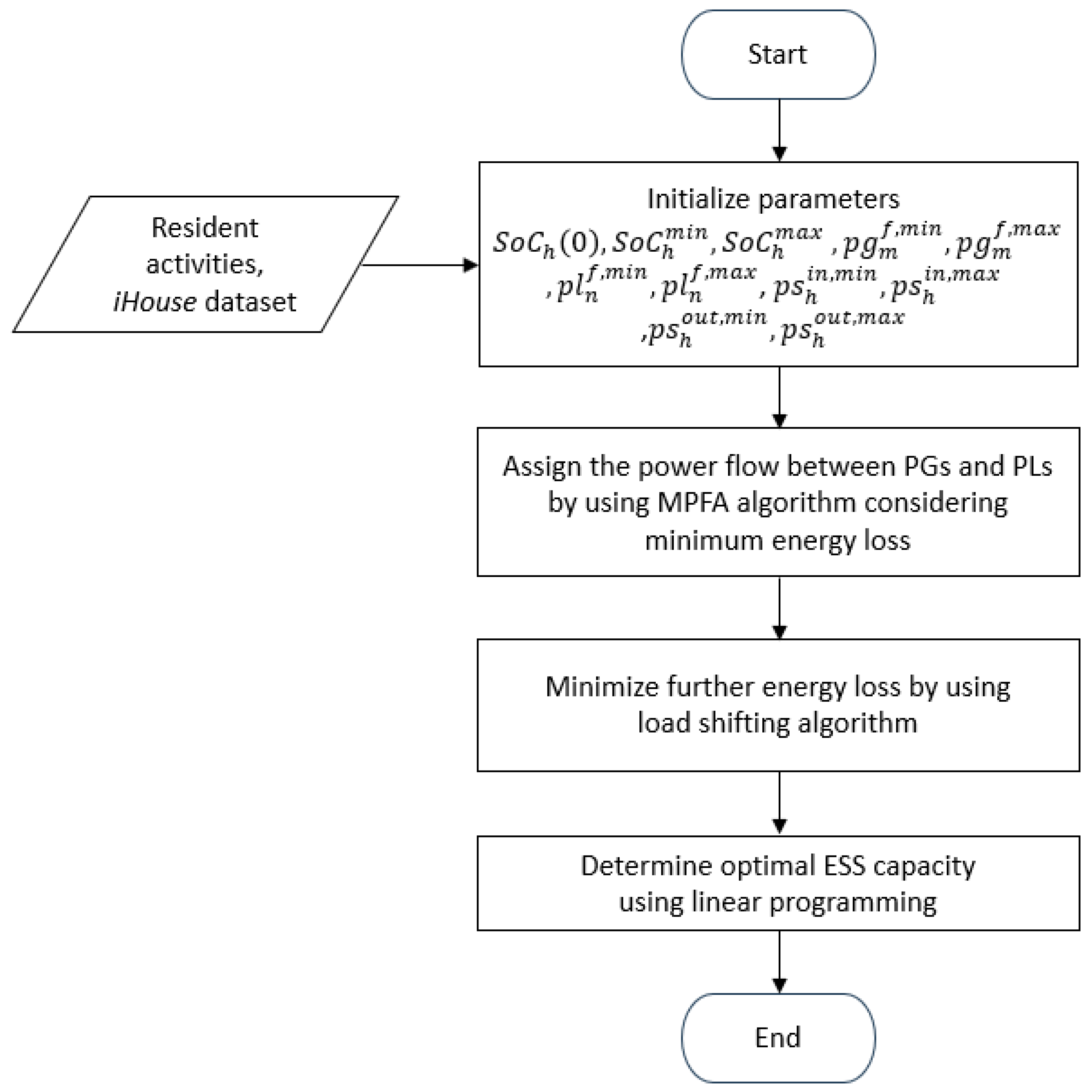
The flowchart of the overall scheme is illustrated in
Figure 4. First, the proposed scheme gathers data from a real experimental dataset of a smart home named
iHouse, along with resident activities, and initializes all necessary parameters. Subsequently, the multiple-load power-flow assignment algorithm is applied to establish power-flow connections between PGs and PLs. After that, the load-shifting algorithm to reduce energy loss is applied. Finally, the reduced optimal ESS capacity is determined using linear programming.
5.1. Admission Control
In a DPFS within a smart home environment, a controller engages in message exchange with all PGs and HADs. The controller may calculate the overall energy supply from power generators and the total energy requests from PLs after receiving these communications.
Figure 5 shows the state change of the admission control scheme.
The figure illustrates three main entities: the controller, HADs, and RE sources, which communicate through a communication channel, interacting with each other. The first operation, in F1, when HADs require energy to operate, involves sending a signal to the controller. Subsequently, the controller registers the HADs’ information and requests. Then, in F2, the controller performs calculations and scheduling based on the demand of HADs. If the demand cannot be met (F3), the controller initiates negotiations with HADs using the proposed SCALE scheme to shift their operating time to a new time slot. In the F3 stage of admission control, algorithms are proposed to negotiate the lowest energy loss for the entire distributed power-flow system. If the new schedule can be settled, the controller performs rescheduling in F4. Moreover, tailoring the admission control mechanism to the demand and preferences of users is possible by indicating the priority energy class of any of the HADs. For instance, HADs with a shiftable mode can be programmed to operate during times when energy supply exceeds energy needs. In this paper, further examination will be conducted on this criterion for a DPFS in a smart home environment.
5.2. Multiple-Load Power-Flow Assignment
This subsection provides details on how MPFA works. In MPFA, each PL draws power from multiple PGs and, additionally, from either a single or multiple PS units. The surplus energy is stored either in a single PS unit or multiple PS units, depending on whether the system is MPFA/SG or MPFA/MG. The logical connections of these MPFA types are illustrated in
Figure 6.
In the MPFA/SG configuration, several PLs receive energy based on the circumstance under which each PS unit acquires the remaining energy from a single corresponding PG (SG). Subsequently, each PS unit further supplies only a single corresponding PL. To illustrate, both the FC and PV sources can simultaneously provide energy to the HADs, namely, the AC unit and the VF. However, the FC can only store generated power in
, and similarly, the PV system can only store power in
. In scenarios where the FC generates insufficient energy for the AC unit,
can discharge the stored energy to turn on the AC unit. Similarly, in the case of the PV system supplying energy to the VF,
helps provide the required energy, as shown in
Figure 6a. The goal of the MPFA/SG algorithm is to guarantee the direct supply of the total energy from the PG to all PLs. The remaining energy of the PG is then utilized to charge the single PS unit.
Figure 7 illustrates the flow chart of MPFA/SG.
Conversely, in MPFA/MG, multiple PLs draw energy from both multiple PGs and multiple PS units. Each PS unit obtains the remaining energy from multiple PGs (MGs) and further supplies multiple PLs. For example, energy can be supplied to the AC unit and the VF by both the PV system and the FC simultaneously. Then, both
and
can equally store the excess energy from both the FC and the PV system. Additionally, energy can be concurrently obtained by the AC unit and the VF from both
and
, as shown in
Figure 6b. The aim of the MPFA/MG algorithm is to prioritize the direct supply of the total energy from the PG to all PLs. The residual energy of the PG is evenly distributed to charge multiple PS units.
Figure 8 depicts the flow chart of MPFA/MG.
5.3. Load-Shifting Algorithm
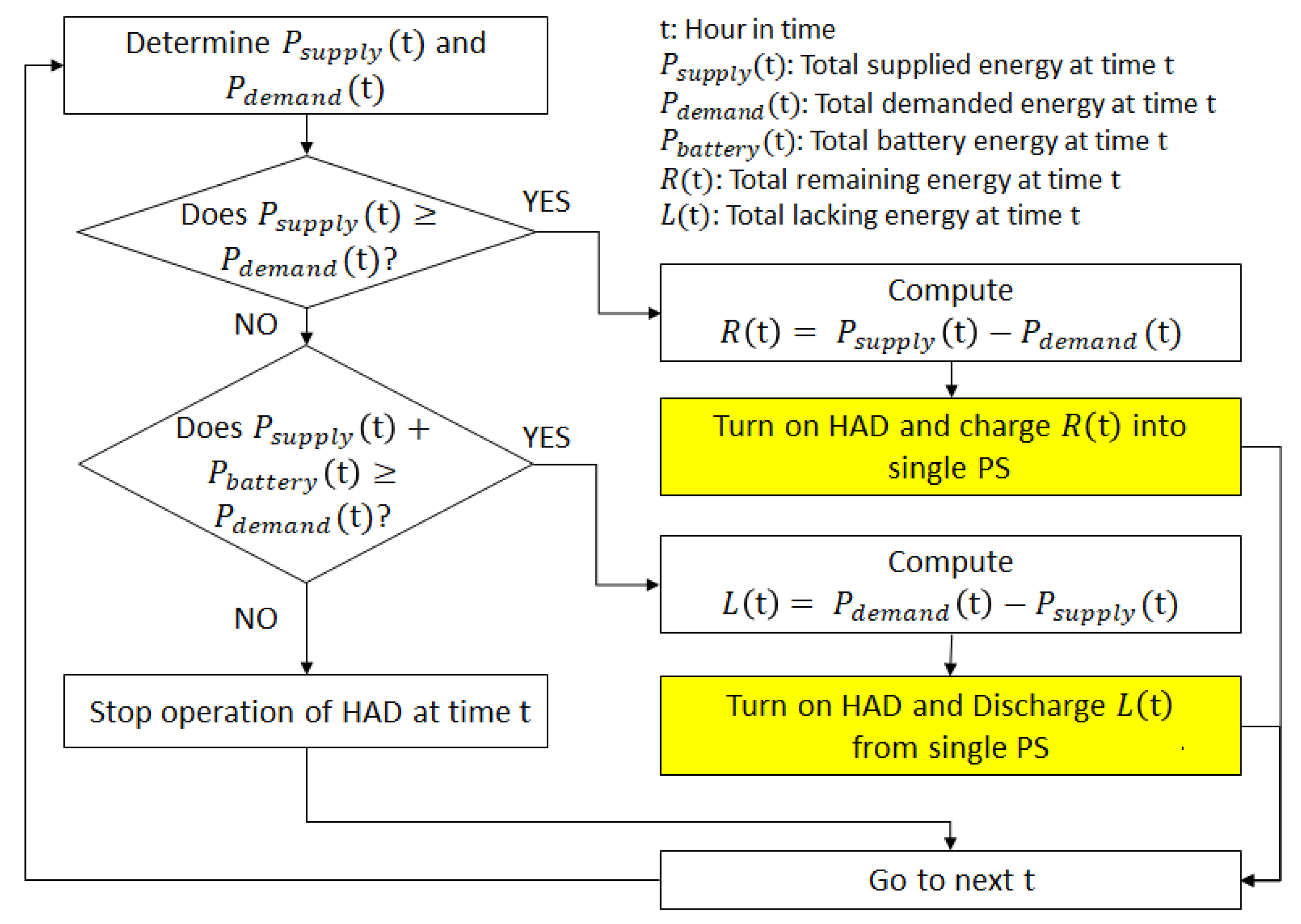
The load-shifting algorithm’s flowchart is shown in
Figure 9. The algorithm first establishes for how many hours shifting HADs may operate. The operating time of shifting HADs is thus moved into different time slots while minimizing energy loss in the PS system. Lastly, the controller notifies all shifting HADs with the new time slots.
We further define additional parameters used in executing the proposed scheme, as these parameters will be used in the upcoming flowcharts: is the total supplied energy at time t; is the total demanded energy at time t; is the total battery energy at time t; is the demanded energy of shifting HADs; is the energy deliverable to shifting HADs; is the total remaining energy at time t; and is the total lacking energy at time t.
5.4. Optimal Energy Storage Capacity Computation
The optimal energy storage capacity is determined by formulating a linear programming minimization problem constrained by two assignment conditions [
11,
12]. These conditions ensure the normal operation of PS systems by maintaining energy generation and consumption within SoC bounds.
In the context of a connection (
,
), the notation
denotes the set of neighboring devices of
. The specific notations of
,
, and
are employed to represent neighboring power generators, power loads, and power storage systems, respectively. For further details, please refer to [
11,
12].
6. Simulation Results
6.1. Simulation Setup
In this section, the evaluation of the effectiveness of MPFA with and without the load-shifting algorithm in a smart home environment is performed, aiming to minimize energy loss and identify the optimal energy storage capacity. The study involves two power generators, namely, a PV system and an FC; two power loads, namely, an AC unit and a VF; and two PS units. Simulations are conducted for two different seasons, summer and winter, chosen due to high demand, especially for heating, ventilation, and air conditioning.
For the PV system and the FC, real experimental datasets obtained from a smart home named
iHouse in Ishikawa, Japan [
38], are utilized, where the rated voltage is 110 V and the frequency is 50 Hz. The data for the two seasons correspond to 14 June 2016 (summer) and 11 January 2017 (winter). The reason we performed the study considering only a single day is that we introduced and applied the MPFA algorithm, where both PGs and PLs could fluctuate throughout the day. Thus, it was essential to analyze the data on an hourly basis within a day. In many of our previous works, we utilized this dataset to study various aspects, including optimal energy storage capacity design, distributed power flow assignment, admission control algorithm, and more [
13,
33,
38]. As we are still in the process of designing the system, we aimed to use the same set of data to extend our work and continually improve system efficiency, such as reducing energy loss and optimizing the energy storage system capacity, as demonstrated in this paper. The average daily temperature is 4 °C; the average relative humidity is 77%; and the mean sunshine duration is 5.2 h in January. In June, the average daily temperature is 25 °C; the average relative humidity is 79%; and the mean sunshine duration is 13.2 h. The FC model is based on ECOFARM [
39], with specified operation times from 00:00 to 06:00 and from 14:00 to 24:00 for both seasons. The energy generation of the PV system and the FC in summer and winter are shown in
Figure 10a and
Figure 10b, respectively. The AC unit and VF work together to regulate the temperature in the smart home, ensuring thermal comfort mode. These PLs follow a 24 h schedule based on the daily activities of a four-member household (father, mother, and two children) [
40]. The members in the household intend to use the AC unit during the intervals 00:00–04:00 and 05:00–24:00 in summer and during the intervals 00:00–04:00 and 08:00–24:00 in winter. The VF operates three times a day, i.e., 05:00–06:00, 12:00–13:00, and 17:00–18:00 in both seasons. Regarding the PS parameters, the initial SoC, minimum SoC, and maximum SoC are set to 21%, 20%, and 94% of the capacity, respectively. (In this work, we set the minimum SoC to 20%, which is already widely accepted and used in the literature [
11,
41,
42]. However, it is important to note that the minimum SoC can impact the battery storage lifespan. To extend the battery life, a higher minimum SoC can be employed, preserving and prolonging the battery life. This is especially crucial considering the high cost of batteries in the system.) The charging and discharging efficiency of both PS units (
,
) is configured as 92% [
13,
33]. All simulation parameters and settings are presented in
Table 1.
For optimal energy storage capacity design, the optimization problem is solved using the linear programming solver in MATLAB R2022b.
In this proposed scheme, analysis is conducted on two different types of results, energy profile results and energy storage results, using two different types of MPFA (MPFA/SG and MPFA/MG) with and without the load-shifting algorithm in two different seasons. The energy storage results consist of energy loss and optimal energy storage capacity results.
6.2. Energy Profile Results and Discussion
Figure 11,
Figure 12,
Figure 13 and
Figure 14 illustrate the energy profiles over 24 h for MPFA/SG and MPFA/MG during both winter and summer. The white bars represent the total generated energy from power generators, while the gray bars represent the total consumed energy of PLs without the load-shifting algorithm. The black bars depict energy demand when the load-shifting algorithm is applied. The results vary between the seasons due to fluctuations in energy generation and demand.
In
Figure 11 and
Figure 12, the energy profiles for winter are displayed for both MPFA/SG and MPFA/MG, with and without the load-shifting algorithm. Both profiles exhibit a similar demand pattern, where no power-flow assignment (PFA) can satisfy all the energy demand throughout the day. This is primarily due to the high energy demand of the AC unit, for which the PV system and the FC do not generate enough energy to cover the entire day. Even MPFA/MG with multiple PS units cannot meet all PL demand during that day.
Figure 13 and
Figure 14 display the energy profiles in summer for MPFA/SG and MPFA/MG, respectively. These results reflect similar patterns as in the winter season, with both MPFA/SG and MPFA/MG struggling to meet all energy demand throughout the entire day.
When comparing the results between the cases of applying and not applying the load-shifting algorithm in winter, the results show that the load-shifting algorithm adjusts the operating hours of the AC unit to reduce energy loss. This shift enables the AC unit to operate continuously in the early evening, as the demand is shifted from the morning. On the other hand, when the load-shifting algorithm is applied in summer, it can be observed that the demand tends to shift from early morning to mid-morning.
6.3. Energy Storage Results and Discussion
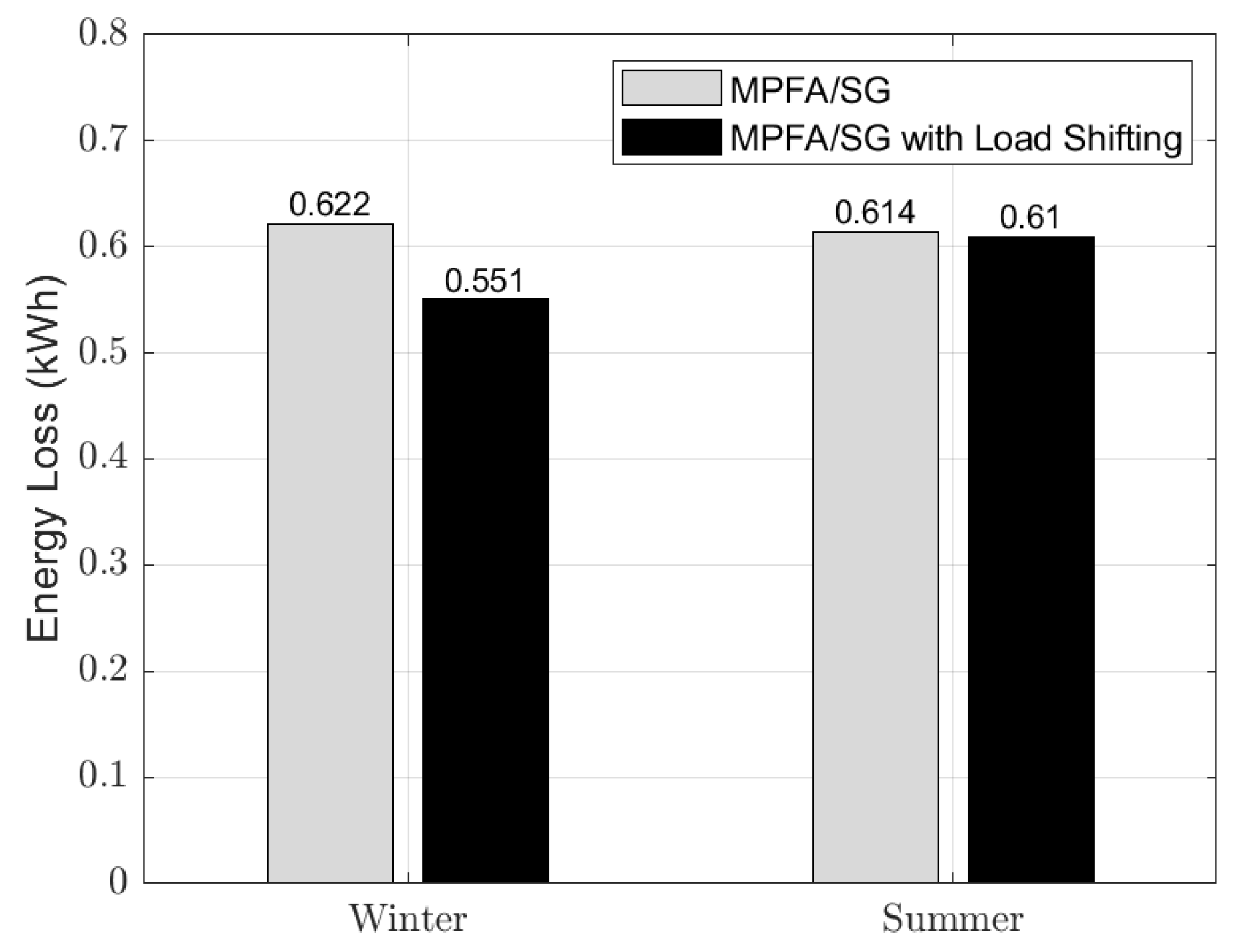
Figure 15 and
Figure 16 display the energy loss comparison in both winter and summer seasons with and without the load-shifting algorithm for MPFA/SG and MPFA/MG, respectively.
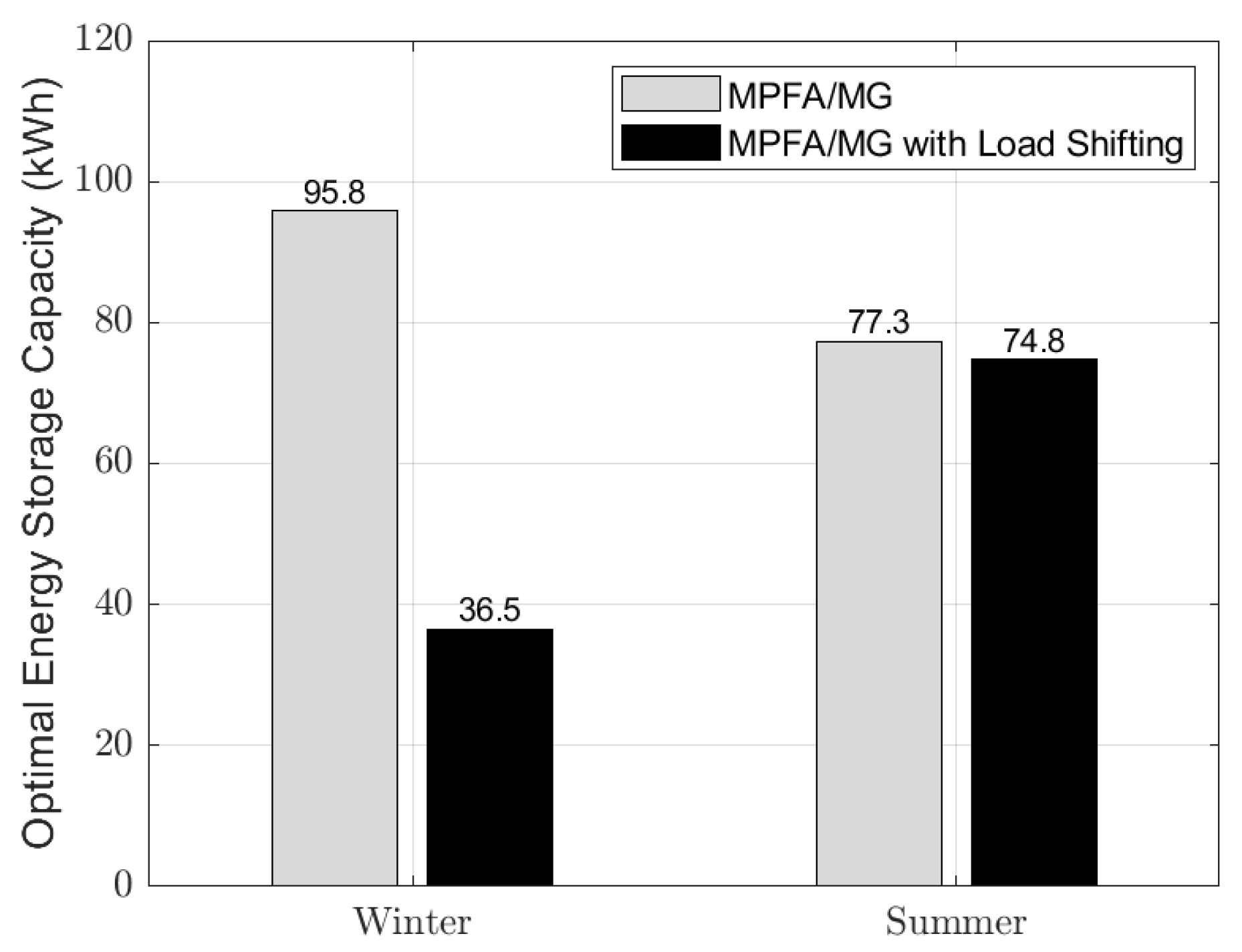
Figure 17 and
Figure 18 illustrate the optimal energy storage capacity comparison in both winter and summer seasons with and without the load-shifting algorithm for MPFA/SG and MPFA/MG, respectively.
When comparing the cases of applying and not applying the load-shifting algorithm, the results demonstrate that the shifted profiles for both seasons have lower energy loss, reduced by approximately 1.4% and 11.4% for summer and winter, respectively. Reductions also occur for the optimal energy storage capacity when applying load shifting, with reductions of 6.7% in summer and 62.1% in winter.
Comparing the results between the two seasons, in terms of the difference in energy loss when not applying the load-shifting algorithm, there is not a significant distinction. However, in cases where the load-shifting algorithm is applied, the winter season experiences a substantial reduction in energy loss, with approximately 9.9% lower energy loss compared with summer.
In summary, MPFA/MG in winter demonstrates the highest reduction in both energy loss and optimal energy storage capacity. This is credited to the effective load-shifting algorithm, supported by multiple PS units, which appropriately shifts the AC demand. Additionally, higher energy demand in the winter season leads to lower energy loss and a smaller optimal energy storage capacity due to a lower amount of surplus energy available for charging in the PS system, while in the summer season, reductions in both energy loss and energy storage capacity also occur, although not to the same extent as in the winter season.
This work possesses some limitations: The SCALE scheme does not address robustness and reliability problems, which will be our focus in future work. Since simulation for a single day is conducted to verify and justify the design of our SCALE scheme, in our near-future works, we plan not only to investigate the aforementioned problems but also examine the SCALE scheme’s performance in terms of the scalability problem by increasing the number of HADs in the simulation over a more extended period, e.g., one week or one month.
7. Conclusions
This paper investigates the minimization of energy loss in an ESS within a smart home environment. This study employs a load-shifting algorithm incorporated with two types of DPFA, namely, MPFA/SG and MPFA/MG. This study also explores the optimal energy storage capacity when applying the load-shifting algorithm, formulated as a linear programming problem. Real experimental data from a smart home environment called iHouse in winter and summer are utilized for design, performance, and investigation.
Specifically, applying the load-shifting algorithm with MPFA during winter results in a significant reduction in energy loss, approximately 11.4%. Additionally, the optimal energy storage capacity experiences a substantial reduction, 62.1%, benefiting from the support provided by multiple PS units to meet energy demand. On the other hand, in the summer season, reductions in both energy loss and optimal energy storage capacity also occur, although not as much as in the winter season. In summer, energy loss is reduced by approximately 1.4%, and there is a 6.7% decrement in optimal battery storage capacity.
The analysis and findings suggest that higher energy demand, as observed in the winter season, leads to lower energy loss and smaller optimal energy storage capacity due to a lower amount of surplus energy available for charging in the PS system. Recommendations include shifting the operation of the loads to the time when the amount of energy supply closely matches energy demand in order to reduce energy loss and optimize the energy storage capacity of smart homes. We plan to extend our analysis by incorporating a greater number of HADs, each assigned a distinct priority class, within the constraints of limited total energy supply. Additionally, we aim to address fluctuations in power supply and variations in demand within the DPFS, considering the irregular daily activities of residents.

 ,
, 


