Article

Biomimetic Drones Inspired by Dragonflies Will Require a Systems Based Approach and Insights from Biology

1
UniSA STEM, University of South Australia, Mawson Lakes, SA 5095, Australia
2
Joint and Operations Analysis Division, Defence Science and Technology Group, Melbourne, VIC 3207, Australia
3
Aerospace Division, Defence Science and Technology Group, Melbourne, VIC 3207, Australia
4
Department of Aerospace Engineering, Faculty of Engineering, Universiti Putra Malaysia, 43400 Seri Kembangan, Malaysia
*
Author to whom correspondence should be addressed.
Submission received: 1 March 2021 / Revised: 21 March 2021 / Accepted: 21 March 2021 / Published: 27 March 2021
(This article belongs to the Special Issue Feature Papers of Drones)

Abstract

:
Many drone platforms have matured to become nearly optimal flying machines with only modest improvements in efficiency possible. “Chimera” craft combine fixed wing and rotary wing characteristics while being substantially less efficient than both. The increasing presence of chimeras suggests that their mix of vertical takeoff, hover, and more efficient cruise is invaluable to many end users. We discuss the opportunity for flapping wing drones inspired by large insects to perform these mixed missions. Dragonflies particularly are capable of efficiency in all modes of flight. We will explore the fundamental principles of dragonfly flight to allow for a comparison between proposed flapping wing technological solutions and a flapping wing organism. We chart one approach to achieving the next step in drone technology through systems theory and an appreciation of how biomimetics can be applied. New findings in dynamics of flapping, practical actuation technology, wing design, and flight control are presented and connected. We show that a theoretical understanding of flight systems and an appreciation of the detail of biological implementations may be key to achieving an outcome that matches the performance of natural systems. We assert that an optimal flapping wing drone, capable of efficiency in all modes of flight with high performance upon demand, might look somewhat like an abstract dragonfly.

1. Introduction

From emergence until death, the flight performance of the dragonfly is tested. Typically, males establish and fight to maintain a territory with favourable oviposition sites after a short period of orientation following emergence. This involves perpetual, dangerous, aerial combat against male rivals, with only the best aviators achieving the territory needed to breed. Mating requires an aerial pursuit of females that innately stresses the flight performance of males. Upon successfully overcoming the female’s defences against weak fliers, successful mating often requires the males to carry the female’s inert mass. Throughout all of this aerial combat, aerial predators are a constant threat, requiring defensive air combat maneuvers at regular intervals. Most combat is over a water surface, under which predators lurk and from which a dragonfly is unlikely to extract itself. Finally, feeding is an effort in pursuit and counter-evasion against prey animals, the evolution of which is also locked in a deadly loop with the dragonfly’s evolving flight performance. It is a life of aerial combat, pursued for 300 million years, by the oldest extant form of flying insect, the archetypal member of Palaeoptera [1,2].
It can be argued that dragonflies have made the least accommodation for other practicalities of existence of any flying insect. Long, unencapsulated, permanently horizontal wings sprout from a heavily muscled thorax, while their large, high-resolution eyes float on a delicate retractable gimbal neck to stabilise sensory input, all optimised for flight and combat. Dragonflies are so highly adapted to flight that their limbs are more suited to aerial grappling than walking; a grounded dragonfly serves no evolutionary purpose and the bloodless wings of adult insects do not heal. Evolution has committed the dragonfly to its aerial life. The single-role lifestyle of adult Odonata is the motivation for our attempt here to understand their critical system level characteristics, so that we can chart a course to a high performance flapping wing drone.
Dragonflies have been shown in quantitative studies to demonstrate superior flight performance compared to most other insects. Scale must be considered in this assessment, as the Odonata order contains relatively large species, particularly in terms of wingspan. The nature of aerodynamics ensures that larger species with longer wings have a physics advantage in some aspects of flight. Dragonfly mastery of the air has been shown in a number of studies based on high speed video analysis of normal flight, aerial combat, and predation. High-performance turning flight has been shown, with loads in turns exceeding 40 m/s 2 [3] and an ability to takeoff while carrying more than three times their own body weight [4]. Dragonflies have been shown to pursue prey animals using the chasing strategies found in missiles [5] and to have exceptionally high success rates in capturing aerial prey [6,7]. They have been found to exhibit advanced guidance laws that camouflage their apparent motion with respect to their opponent [8,9] using means that have not been convincingly identified. It has been demonstrated that they have a surprisingly efficient glide performance comparable to that of model aircraft with substantially higher Reynolds numbers ( R e ). Observed lift-to-drag ratios range from 3.5 to over 10 [10,11,12]. Some species of dragonfly have been observed to migrate across hundreds of kilometres [13], a difficult, energetic achievement for such a small organism. Energy scavenging by dragonflies has also been observed: they soar on thermal updrafts and on rising air currents caused by slopes [14]. The evolutionary argument and the measured realities of dragonfly mastery of flight align, indicating that they may be the apex insect flyer. The challenge is to understand the ingredients of this design so that technological systems might be able to achieve some of the same characteristics.

Biomimetics and Bioinspiration

Biomimetics is a broad approach, without a standard methodology. The range of techniques is a spectrum from “inspiration” to “mimicry”. The two extremes on this spectrum have limitations. Inspiration might entail simply looking at the outside of a biological system such as a dragonfly, which might help the engineer to decide what application to create: for example, an insect-styled drone. This allows the imagination to be channeled and certainly is a valid engineering approach, complete with expectations and requirements. However, the solution is the result of engineering and does not create a particular head start for the engineer. Inspiration might even create undue constraints, since the operating principles applied might be quite different than in the organism. Mimicry creates problems of technological incompatibility between the solutions grown by biology and the highly refined mechanisms in common engineering use. Essentially the components required to make a copy often do not exist. For example, conventional technologies for motion are rotational, yet the known rotating motor in nature is a flagellum with parts on a molecular scale [15], while large motive systems are based on muscle. Artificial muscles, on the other hand, remain elusive. The problems of copying solutions becomes even deeper when organs and cellular mechanisms start to be considered, showing clear limitations to the mimicry approach.
Srinivasan has advocated an approach that accepts the differences in component technology but ensures that the principles of operation are preserved [16]. In many cases, it is inviolable system characteristics that allow the organism to operate, not details of implementation. We will assert that this is the case with dragonflies, despite all appearances. This approach requires an understanding of both the class of technological system being created and of the biological system being mimicked. This argument is supported by the failures of early ornithopters. Despite detailed bird anatomy and observations, there was, at first, no understanding of aircraft. Subsequent work identified the role of mass, balance, and wings, allowing a progression from Cayley [17], to Lilienthal [18], and culminating with the Wright Brothers [19]. In the case of flight, it seems that the path to success required a systematic approach to research into underlying principles and that biomimicry did not provide a substantial shortcut, other than for inspiration.
Dragonfly ocelli are an accessible anecdote of biomimicry used to create a unique technological sensory capability. Dragonflies have evolved a highly specialised second set of eyes and reflexes for stabilisation of flight using the horizon, even in dim light. Evolution has chosen specific spectral bands of ultraviolet and green to maximise discrimination between sky and ground [20]. Construction of functional synthetic ocelli for aircraft required photodiode arrays with sensitivity to appropriate spectral bands; it did not require the building of an eye [21]. The reasons such a device had not been conceived of before were that (i) Stange in the 1970s [22] was not aware that unmanned aircraft was an issue, hence the 20 year gap before a follow-up study [23] and implementations [24], (ii) the world that is visible in the ultraviolet region is outside the human experience, (iii) inertial sensors have been adequate for drones with steady flight patterns and heavily aided by global positioning systems, and (iv) the need for extreme agility and rapid inertial realignment in very small aircraft that exceed current inertial sensor capabilities had not yet appeared. This also shows that knowledge of both the system being mimicked and the class of technological system being created is almost a necessity for the successful adoption of biomimetic concepts.
Aeronautical systems are highly optimised in ways that are not generally appreciated when the rule-based design of conventional aircraft is undertaken. In this case, convention conceals complexity. For the sake of comparison, we present 3D models of a wing, a rotor, and a dragonfly wing in Figure 1. It is likely that all are close to their maximum possible performance, by whatever means that might be measured, but one appears to have more degrees of freedom and is used in more complex ways.
The remainder of the paper will explore key interrelated systems that are substantially different to fixed wing, multirotor, or wing/rotor chimera craft, but are critical to the flight of a conceptual biomimetic high-performance drone. We will also present experimental evidence showing how critical these functions are. We will propose a technology path to achieving this ambitious goal.

2. Wing Performance and Structure

Micro air vehicles (MAVs) designed to mimic the flight of dragonflies must have well understood aerodynamics. There have been numerous studies on the aerodynamic design and control of dragonfly biomimetic MAVs [25]. Some of the most basic factors include R e , wing aspect ratio ( A R ), and wing structural properties.
The flow on and around an aircraft is affected by aircraft size and flight speed. R e , the ratio of inertial forces to viscous forces, is a non-dimensional parameter used to scale and compare flow regimes of air vehicles:
R e = U r e f L r e f ν ,
where U r e f is the reference velocity, L r e f is the reference length, and ν is the kinematic viscosity of the fluid. The smaller the R e , the larger the viscous effects. R e is proportional to reference length and reference velocity. R e decreases with decreasing wing size. Insects operate at low R e ( 10 4 to less than 10 2 ), where both inertia and viscous effects are important. This regime is characterised by an unsteady laminar flow, involving strong vortices [26]. At low R e , the viscous effects are so large that the leading-edge vortex (LEV) is separated, resulting in little lift generation and high drag [27]. Insects take advantage of unsteady aerodynamics associated with low R e using a variety of documented mechanisms: a rapid pitch-up, a delayed stall of the LEV, wake capture, clap-and-fling mechanisms, and interactions between the LEV, the trailing-edge vortex (TEV), and the tip vortex [28], to generate the necessary lift. We will continue our analysis without further consideration of these mechanisms because they are each R e -specific techniques and do not appear to be necessary to explain the dragonfly design.
Compared to fixed wing flight, the aerodynamics of dragonfly flight is more complex. Researchers have proposed a variety of different methodologies to produce aerodynamic analysis, either using experimental techniques or simulation. One study reconstructed the glide paths of dragonfly flight by filming the flight in a large enclosure [10]. The aerodynamic forces were measured from isolated wings and bodies in a steady air flow at an R e from 700–2400 for the wings and 2500–15,000 for the bodies. Using these methods, it was found that dragonfly wings demonstrate superior steady-state aerodynamic properties compared to wings of other insects. In another study, the aerodynamic characteristics of dragonfly wing and conventional airfoils were compared by measuring the lift and drag coefficients at an R e of 7880 and 10,000 using a force balance system [29].
Hu et al. [30] investigated the aerodynamic effect of wing–wing interaction on the dragonfly flight using a flapping model dragonfly. The model was submerged in a tank of mineral oil and mounted on a six-component force sensor that measured the forces and torques, comprising wing aerodynamic force, wing mass, and wing inertial force. Results from the experiment showed that wing–wing interaction increases fore wing (FW) lift in forward flight while reducing hind wing (HW) lift at all wing beat phase differences. Using computational fluid dynamics (CFD), it was found that aerodynamic performance improved due to FW–HW interaction during gliding motion for angles of attack ranging from 0 to 25 [31]. CFD has been used to estimate the aerodynamic performance of free flying dragonflies [32]. The spanwise features of vortex interaction between the FW and HW were investigated, and it was found that the flow structure around both wings resulted in increased horizontal force (thrust) generation.
A key difference between dragonflies and flies are their long slender wings. Figure 2 shows a robber fly wing on the left and a dragonfly wing on the right. A R is generally a strong indicator of how a wing performs. The A R of a wing is defined by the ratio of the wingspan to the mean chord as follows:
A R = b r e f 2 S r e f ,
where b r e f is the reference wingspan, and S r e f is the reference wing area.
Wingtip vortices have a deleterious effect on wing performance; hence, the amount of energy lost due to induced drag can be reduced by reducing the area of the wing tip, by making it pointed or slender, as in [33]. A R and wing area quantify the shape and size of the wing and consequently are an indication of aerodynamic efficiency. Higher A R is indicative of a wing that is relatively narrower. While flow is attached, reduction in A R causes the lift coefficient ( C L ) to reduce for a given angle of attack. Increasing the A R by making a longer and thinner wing improves aerodynamic performance, a tactic commonly employed in modern sailplanes. A longer wing results in a smaller wingtip vortex, which results in a less induced drag, which reduces forward flight energy costs. Reduced induced drag is particularly beneficial for natural flyers that glide at low speed, because at low speed, induced drag dominates the total drag. Long wings are aerodynamically beneficial, but carry obvious consequences for practicality on the ground. It is likely that the evolutionary feature of Odonata having a limited ability to walk is related to their long, fragile, permanently deployed wings.
The wings of dragonflies are a frequently depicted subject of art and jewellery. Amazingly, however, the precise details of a reasonable number of dragonfly’s wings have only recently been recorded and analysed. Capturing even one live dragonfly intact is often a significant undertaking for the uninitiated. Capturing a large number of flying insect species in a systematic fashion is a difficult and expensive project, often a lifelong pursuit. Our project of capturing the wing geometry of 75 Odonata species required the use of scientifically and historically significant museum collections. Examples of these fragile specimens are shown on the left of Figure 3, including some broken specimens with limbs, wings, and abdomens detached. A passive optical technique for measurement was developed that could function through the glass display case [34]. Photos were taken from a linear sequence of positions using a robotic slide, shown on the right of Figure 3. Approximately 100 images of 4016 × 6016 pixels were captured and processed to construct a 3D model of the wings. All specimens remained intact and undisturbed [35].
To obtain a 3D image, the structure from motion technique was used by the 3DF Zephyr software [36] to stitch the captured photographs together. The technique captures colour, visible textures, and structures of the wing. The first 3D reconstructions [34] and quantitative comparisons [37] of a substantial number of Odonata species were published in the year 2020, despite scientific interest in the Odonata for millennia. Typical outcomes are shown in Figure 4.
Dragonfly wings have a comparatively high A R . They are corrugated [38,39,40], with complex vein patterns along chord and span. The veins contain blood on emergence, which enables the wings to unfurl. Soon after emergence, the blood supply is cut off, so the wings and veins are not living tissue [2]. Spanwise, the corrugations vary and flatten as they reach the wing tip. In [29], Kesel compared the aerodynamic efficiency at low R e of an extruded 2D corrugated aerofoil section and a flat plate section. For an ultra-low R e , between 2000–3000, aerodynamic performance of corrugated aerofoils at several angles of attack from 0 to 15 have been studied in addition to the lift-to-drag ratio [41]. Subsequent work has visualised airflow over the wings using particle image velocimetry (PIV) compared against computational fluid dynamics [42,43,44,45]. These flow studies have shown the effect of different levels of structural detail on flow separation of both real wings and manufactured wings, at various angles of attack. The general principle of corrugated wings has been shown to be the formation of profile valleys in which rotating vortices develop. These vortices reduce friction and maintain attached flow at higher angles of attack than on a flat plate or a conventional aerofoil [29]. Aerofoils formed by transects of a dragonfly wing are shown in Figure 5.
Typically, corrugation enhances aerodynamic performance, while stiffening the wing. However, in the range of very low R e , it has been found that corrugations may produce undesirable aerodynamic effects [46]. Fixed wing aircraft interpretations should be used with caution, however, since drag might be desirable in some modes of flapping flight. CFD was employed to analyse the flow fields and surface pressure distributions of corrugated and flat-plate wings at low R e ranging from 200–2400. It was found that the lift coefficient was lower for the corrugated wing, particularly at lower angles of attack. Strongly corrugated wings are definitely stiff, yet aerodynamically they are a solution to a specific range of R e . Research continues on the systematic measurement of smaller insect wings. Our comprehensive data set of dragonfly wings allowed for detailed computational flow visualisation and the manufacture of reconstructed 3D test wings for physical flow field visualisation.
Experimental analysis of flow over the full 3D wing, complete with measured micron-scale features, was performed to explore the effect of reconstructed natural surface texture on flight performance at low R e . The flow patterns were analysed at an angle of attack of 10 and R e = 5 × 10 3 , R e = 8 × 10 3 , and R e = 12 × 10 3 , showing better performance than that found in previous studies based on extruded 2D corrugated aerofoils [47].
The influence of corrugated FW/HW at low R e was investigated by the authors. The results were compared with the same size and planform flat wing. The PIV technique was applied on the manufactured wings. The flow characteristics and boundary layer of the bioinspired wings were measured. Figure 6 shows the instantaneous spanwise vorticity around corrugated profiles and flat profiles at R e = 3 × 10 3 with α = 0 and α = 10 . The fabricated corrugated wing provides substantially better aerodynamic performance than a flat wing in terms of delaying flow separation.
Analysis of a fully replicated HW, complete with 10 micron scale texture, in gliding flight, at low R e , was performed to study its aerodynamic characteristics. Computational results were verified against experimental results with good agreement. Figure 7 compared lift and drag measurements of corrugated and flat wings at α = 10 and R e = 22 × 10 3 (left) and pressure distribution from a corrugated wing at α = 10 and R e = 6 × 10 3 (right).

Lessons from the Dragonfly Wing

A stiff wing, weighing less than 2% of the body of the animal, achieves a better lift-to-drag ratio than a flat structure and performs at low R e where conventional aerofoils are poor. Dragonfly wings appear to be more efficient than expected, particularly at low speed, while still retaining attached flow at high angles of attack, yielding both high lift and high drag on demand. Drag and lift are both associated with the damping property identified in Section 4, which allows nearly all energy put into the wing by the flight motor to be delivered in a controlled fashion to the air. The electron microscope images in Figure 8 show the detail of the dragonfly wing. The precise and self-similar features suggest a highly evolved weight and stiffness optimisation that will be quite hard to replicate and yet may be necessary for an efficient implementation.

3. Body Articulation

A distinctive dragonfly feature that has received less attention than the wings is the long abdomen that comprises up to 35% of their body weight [48]. We will show that this adaptation is not potentially useful, but actually vital for a functional biomimetic drone. The abdomen has evolved to serve many purposes. It houses the digestive tract, has anatomical features related to reproduction, and must bend for mating and oviposition [2]. Less obvious roles are in maintaining balance, enhancing stability, and achieving maneuverability in certain situations. The ability to change posture can modify the position of the centre of mass with respect to the origin of aerodynamic forces on the body [49], allowing body posture to be used for flight control. The use of posture changes for control has been observed in land animals, including geckos [50] and cheetahs [51,52]. In insects, posture changes, in the form of strong abdominal steering reflexes, have been observed in response to mechano-sensory or visual stimuli. For instance, a study presented in [53,54] showed that desert locusts (Schistocerca gregaria) respond to an angled wind stimulus during tethered flight with large leg and abdominal movements. Fruit flies (Drosophila melanogaster) demonstrate similar responses to visual rotation [55,56,57]. In addition, modulation of the vertical abdominal angle has been observed in honeybees (Apis mellifera) responding to the speed of a translating visual pattern [58]. Hawkmoths (Manduca sexta) also show strong abdominal responses to mechanical and visual stimuli [59,60]. Dragonflies have been observed to use head movements to target their prey [5], and several videos by Rüppell show dragonfly abdominal movements during flight [61].
As mentioned earlier, the flight dynamics and aerodynamics of flapping wing systems are more complex (and scientifically contested) than that of fixed and rotary wing aircraft. Mathematical modelling helps gain insight into the complexities associated with flapping flight. Several flight dynamics models for insects have been developed in the literature [60,62,63,64,65,66,67,68]; however, most of the models are data-driven for specific insects and, as such, are specific and restrictive in application. Flapping flight dynamics models in the literature, based on laws of classical physics, have neglected effects due to morphological changes. Most studies have focused on hovering or tethered flight. Although hover is important for a dragonfly, it is not their primary mode of flight, as they spend most of their flight time in forward motion [69]. There has been little effort to quantify these effects [70] and little attempt, until recently, to consider the effects of these posture changes on flight performance [71]. The following analysis considers the potential roles of abdominal articulation in an abstracted fixed wing glider at constant speed.

3.1. Equations of Motion

The non-linear equations of motion for a fixed wing aircraft are adapted here to include an abdomen/tail modelled as an added mass, m T , concentrated at the tip of a massless rod [71]. For the purposes of isolating inertial forces from aerodynamic forces on the tail, the aerodynamic effects of the tail were ignored, as these effects are expected to have little influence on the aerodynamics of the aircraft, compared to the wings, legs, and thorax. The central body (head to thorax region) has six degrees of freedom (DoF) in flight. The abdomen has three additional rotational degrees of freedom, constrained to move with the central body about a joint at p o i n t j (see Figure 9). Note that, when the reference frame of a vector or tensor is not explicit, the default is the body-fixed reference frame B.
The translational and rotational dynamic equations are represented by Equations (3) and (4), respectively [71,72]:
V . B I = 1 m F 1 m ( m T [ [ R ] B T [ ω . T B ] T × [ ρ t j ] T + [ ω ˜ T B ] T ( [ ω ˜ T B ] T [ ρ t j ] T ) , + ω . B I × ( [ R ] B T [ ρ t j ] T + ρ j b ) + ω ˜ B I ω ˜ B I × ( [ R ] B T [ ρ t j ] T + ρ j b ) + 2 ω ˜ B I [ R ] B T ( [ ω ˜ T B ] T [ ρ t j ] T ) ] ) ω ˜ B I V B I ,
ω . B I = 1 J b C ( M [ m T [ R ] B T [ ρ t j ] T + ρ j b [ [ R ] B T [ ω . T B ] T × [ ρ t j ] T + [ ω ˜ T B ] T ( [ ω ˜ T B ] T [ ρ t j ] T ) + ω ˜ B I ω ˜ B I × ( [ R ] B T [ ρ t j ] T + ρ j b ) + 2 ω ˜ B I [ R ] B T ( [ ω ˜ T B ] T [ ρ t j ] T ) + V . B I + ω ˜ B I V B I ] ] ) ,
where ρ t b is the position of the tail mass with respect to p o i n t b in the body frame. ω B I and ω . B I are, respectively, the angular velocity and acceleration of the body frame with respect to the inertial frame. [ ω T B ] T and [ ω . T B ] T are the angular velocity and acceleration of the tail mass with respect to the body frame, respectively. Here, m T is the mass of the abdomen/tail, and m is the total mass of the aircraft, while F and M represent the total force and moment acting on the aircraft respectively.
The change in centre of gravity ( c g ) position with respect to p o i n t b , written in the body frame, is expressed as
Δ ρ c b = m T ρ t b m .
where
ρ t b = [ R ] B T [ ρ t j ] T + ρ j b .
The inertia matrix of the whole system about p o i n t b is given by
J b C = J b B + J b T ,
where J b T is expressed as
J b T = m T ( ρ ¯ t b ρ t b ) I ρ t b ρ ¯ t b ,
and I is a 3 × 3 identity matrix.
The elements of the inertia tensor J are
[ J ] = J x x J x y J x y J y x J y y J y z J z x J z y J z z .

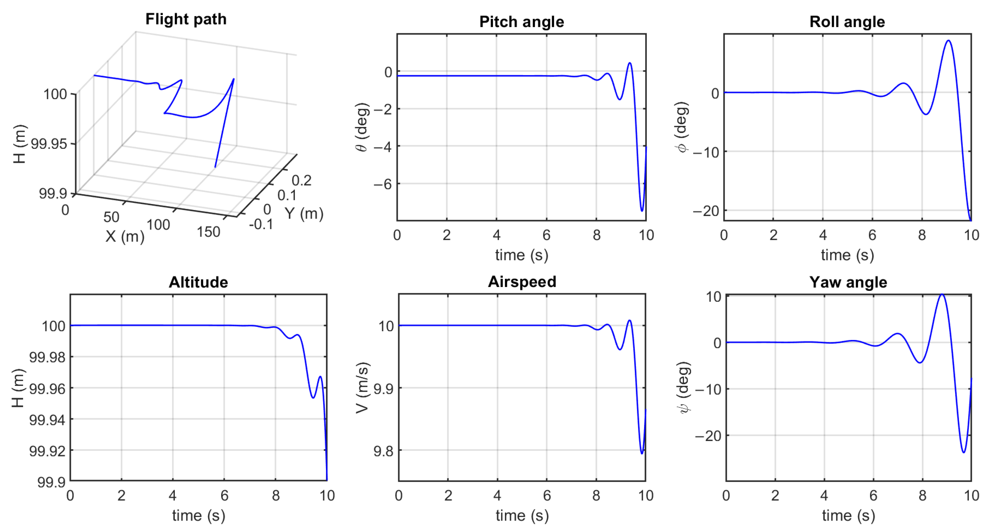
3.2. Flight Simulation for Maneuvering

A dynamics model can be expressed as a function of its states X and inputs U,
X . = f ( X , U )
y = g ( X , U )
Depending on the variables of interest, the output vector y elements can be arbitrary combinations of states and inputs. Matlab’s trim algorithm, which uses sequential quadratic programming [73], was used to evaluate the desired trimmed flight condition values. The states for the aircraft considered were
X = ( u , v , w , p , q , r , ϕ , θ , ψ , x , y , H ) T ,
where ( u , v , w ) are the body velocity components, ( p , q , r ) are the body frame angular velocities, and ( ϕ , θ , ψ ) are the Euler angles that describe the roll, pitch, and yaw of the body, respectively. ( x , y , H ) represents the position of the body relative to the inertial frame. The control inputs are
U = ( δ e , δ a , T n , ϕ T , θ T , ψ T ) T ,
where δ e is the elevator deflection, δ a is the aileron deflection, and T n is the thrust, assumed to align with the longitudinal axis, hence producing no moments. ( ϕ T , θ T , ψ T ) , respectively, are the roll, pitch, and yaw of the abdomen/tail, relative to the body frame.
The flight dynamics model of the conceptual aircraft was simulated in the MATLAB/Simulink environment [74] and the physical properties of the conceptual aircraft with articulated tail/abdomen are shown in Table 1. The fore and hind wing areas were combined to form a single wing with elevons. Depending on the desired flight control response, elevons operate in concert to function as elevators and ailerons. The aircraft was initially trimmed for steady level flight using the elevons as an elevator before the maneuver was initiated with tail/abdomen actuation.

Simulation Results and Analysis

In steady state flight, translational and rotational velocity components in the body frame are constant, so u ˙ = v ˙ = w ˙ = p ˙ = q ˙ = r ˙ = 0 . All analyses we present assume no sideslip. Trim analysis was carried out for level cruise at speed V 0 = 10 m/s and a height of H 0 = 100 m. The tail position was fixed at ( ρ t j 0 = 0.264 m), ( ρ j b 0 = 0.3 m), and the abdomen/tail was undeflected ( θ T 0 = 0 ) . The model was trimmed without actuator dynamics using the Matlab/Simulink linear analysis tool [74]. The trim results for level cruise are presented in Table 2.
A quasi-steady analysis for a pull down maneuver was performed to confirm the response of the abdominal pitch angle ( θ T ) to the control signal input. At altitude 100 m and speed 10 m/s, the duration of the total analysis was 10 s. To examine the longitudinal flight of the aircraft, the abdominal pitch angle control signal was applied as a step response by adding −5° to the trim value of level cruise. Trimmed level cruise thrust was maintained. Figure 10 shows the time course of flight path, altitude, airspeed, and pitch angle in the simulation. The flight path indicates a decreasing altitude from level cruise.
Lateral-directional flight performance was investigated for an abdominal yaw angle ( ψ T ) control input. While maintaining all other controls at their level cruise trim values, an abdominal yaw angle doublet input (symmetrical pulse of equal magnitude and opposite in sign) control signal of 0.5 , of duration 0.5 s, was applied 1 s into the simulation. The duration of the analysis was 10 s. Longitudinal and lateral coupling flight performance of the aircraft was examined. The flight path, altitude, airspeed, and Euler angles of the simulation are presented in Figure 11. It is clear that the aircraft responds by starting to turn with decreasing altitude.

3.3. Integrated Function of Morphological Modifications in Flight

The wings are not the sole contributors to the maneuverability exhibited by insects. Morphological modifications in flight, such as articulation of the abdomen, are used to improve maneuverability or as an alternative source of control in certain scenarios. For instance, despite not having aerosurfaces for roll, pitch, and yaw control such as conventional aircraft, two modes of turning flight have been observed in dragonflies [75]. In the conventional mode of turn, the dragonfly produces more lift and thrust on one side than the other. It then rolls into a bank such that the lift vector has a sideward component, resulting in a turn equivalent to that of a fixed wing aircraft. The “yaw” turn, which is the second turning mode, is achieved without banking; rather, the longitudinal axis of the dragonfly turns, which has now been modelled and simulated, as shown in Figure 11.
Energy savings have been recorded to achieve longitudinal balance and pull up maneuvers by manipulating moments using abdominal articulation as alternative control effectors to conventional aerosurfaces [71]. Overall, a 4–5% average in propulsive power savings was recorded using abdominal movements for the correction of comparatively mild imbalances in steady cruise. Generally, in manned fighter aerial combat, the aircraft with the ability to maintain a higher specific energy and excess power has a greater maneuver advantage [76]. We have reported [71] an average of 1% more specific energy and 1.83% more excess power using abdominal deflection to initiate a steady pull up maneuver, in comparison with using the elevator. In most small electrically powered aircraft, at least 50% of the power available is used for propulsion [77]. Using morphological modifications during flight can save energy and substantially reduce peak power requirements.

3.4. Lessons from Abdominal Control

Dragonflies can grapple and carry prey and females. They can also catch prey with their mouth-parts well ahead of their centre of gravity. With no abdomen, they would have no means to immediately balance the load, losing valuable lift simply to induce an aerodynamic torque to offset mass. Dragonfly flight, like all flying wings, is on the edge of being unstable [78]. A forward shift of the centre of gravity with respect to the aerodynamic centre would certainly allow them to recover stability. Analogous situations for a drone can also be conceived of, particularly if it can drop and collect loads, or if it consumes fuel. Careful consideration shows that the dragonfly and insects generally have their shape and articulation for multiple reasons and that dynamic control of balance is particularly useful. It is challenging to conceive of an alternate solution that is more efficient.

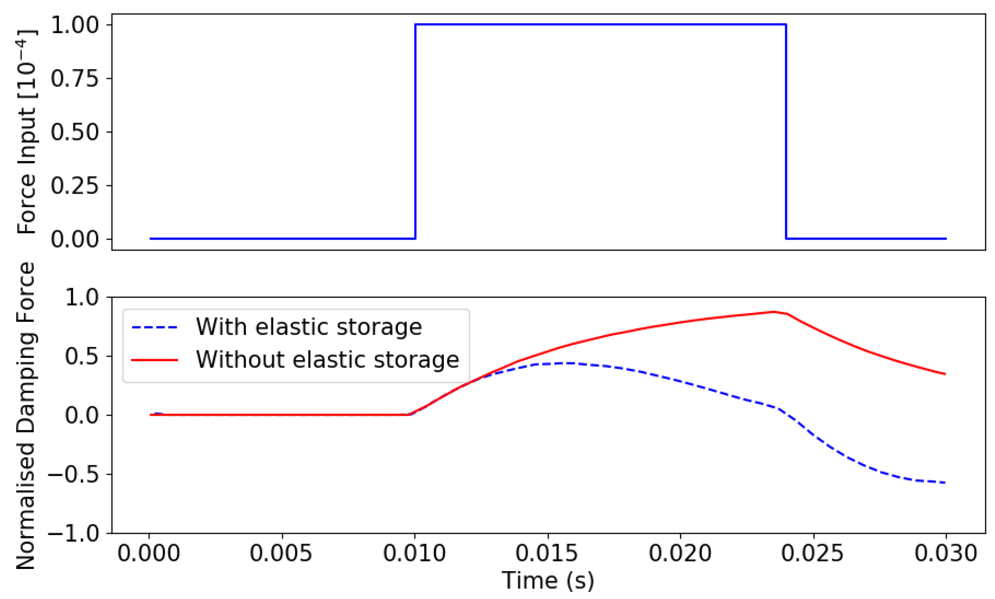
4. Wing Beat System Dynamics

Appreciation of the criticality of each part of a dragonfly requires an understanding of power in the system. An understanding of the power and control of dynamics unravels the reason for the evolution of rigid wings [79] and explains why the dragonfly has retained individual control of each wing beat [75,80,81,82,83,84] and why a technological dragonfly should probably use controlled reciprocating actuators rather than rotating actuators.
In previous studies [79], we have shown that the stiffness of the wing–thorax–actuator structure affects the system level performance of the aerial platform. We compared a pliable mechanism operating in a resonant mode with a more rigid mechanism, in the three dominant modes of flight: hover, glide, and manoeuvre. In hover, wings are driven against inertial, aerodynamic, and elastic forces. The power required to sustain hover can be expressed as the sum of power required to overcome aerodynamic forces ( P A e r o ) and the power required to sustain the continuous acceleration and deceleration of the wing, ( P I n e r t i a ), i.e.,
P H o v e r = P A e r o + P I n e r t i a
Some studies have observed that the use of elastic mechanisms can recover power required to overcome P i n e r t i a [85,86,87]. We have demonstrated a negative impact on performance in gliding and agile flight for systems employing low rigidity and resonant system dynamics to sustain hover. In our study, the inertial and elastic forces were modelled as linear functions, proportional to angular acceleration and position, respectively, i.e.,
E l a s t i c F o r c e = K ϕ
I n e r t i a l F o r c e = I ϕ ¨
where K and I are the spring constant and inertia, respectively, whilst ϕ , the flapping angle, is the relative angular difference between the minimum and maximum position of the wing during flapping. The aerodynamics was modelled using a quasi-steady blade element model, the details of which are found in [79]. Gains of as low as 14% in hover efficiency were observed through the employment of resonance, which were reduced even further when considering a real implementation. A 50–70% reduction in manoeuvring limits was observed when employing resonance compared to a system without an elastic recovery system (i.e., K = 0 ). Figure 12 shows the instantaneous response of the normalised damping force to a unit force input. From this, we observe that by implementing elastic storage, the ability of the system to modulate aerodynamic forces was reduced, even though these forces are critical to manoeuvrability. Additionally, critical glide speed was reduced. Critical glide speed is the speed at which aeroelastic instabilities begin to occur as wings twist and flutter. Fung [88] presented a set of criteria relating critical speed to the stiffness of the system based on Kussner’s formula. According to Fung, critical speed is proportional to the square root of stiffness, K .
These findings support the argument that dragonflies have evolved an apparatus that allows them to efficiently expend energy towards modulating aerodynamic forces as opposed to recovering inertial loss incurred by having heavy wings. The ability to modulate aerodynamic forces is what makes the dragonfly an outstanding natural flyer. This is supported by studies that show that the dragonfly has an aerodynamics-dominated design as opposed to an inertia-dominated design [11,89,90,91].
In addition to having a relatively rigid wing–actuator system, another factor that allows dragonflies to efficiently modulate aerodynamic forces is the control of wing kinematics. Studies have shown that dragonflies have an exceptional amount of control over the dynamics of their wing to the extent that they are able to actively modulate wing stroke, flapping frequency, stroke plane angle, the upstroke-to-downstroke ratio, the phase between fore and hind wings, and the angle of attack of the wing [75,80,81,82,83,84,92,93]. Observations of dragonflies in nature show that they employ various wing kinematics to effect different manoeuvres. However, most robotic flapping platforms rely on rotary mechanisms with transmissions that highly constrain wing kinematics [94,95,96,97,98,99], whilst other designs rely on resonant mechanisms that constrain them to efficient flight only when hovering [85,95,100,101].
Therefore, we make the case that the design of a wing–thorax–actuator system that is able to mimic the capabilities of the dragonfly will require relatively rigid structures that do not rely on resonant modes for achieving flight. In addition, it requires a reciprocating actuator, or set of actuators, that have a high level of control over wing kinematics.

Lessons from System Dynamics
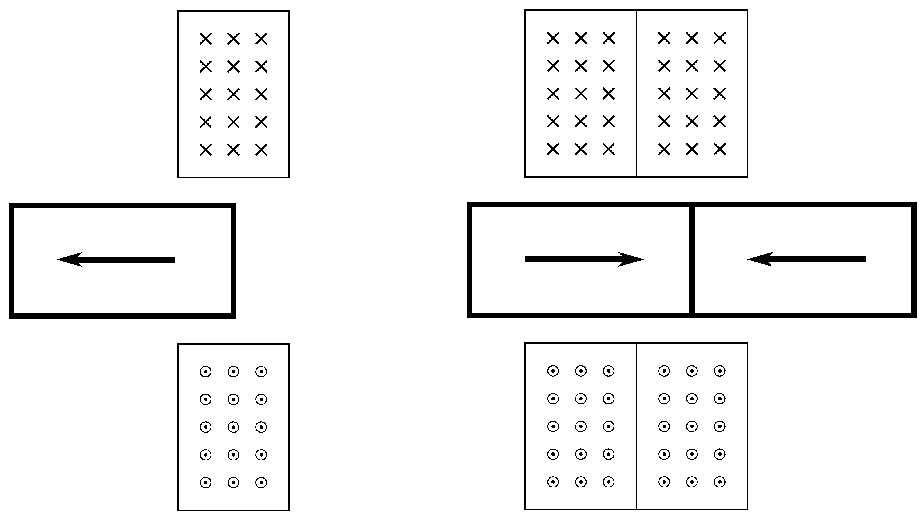
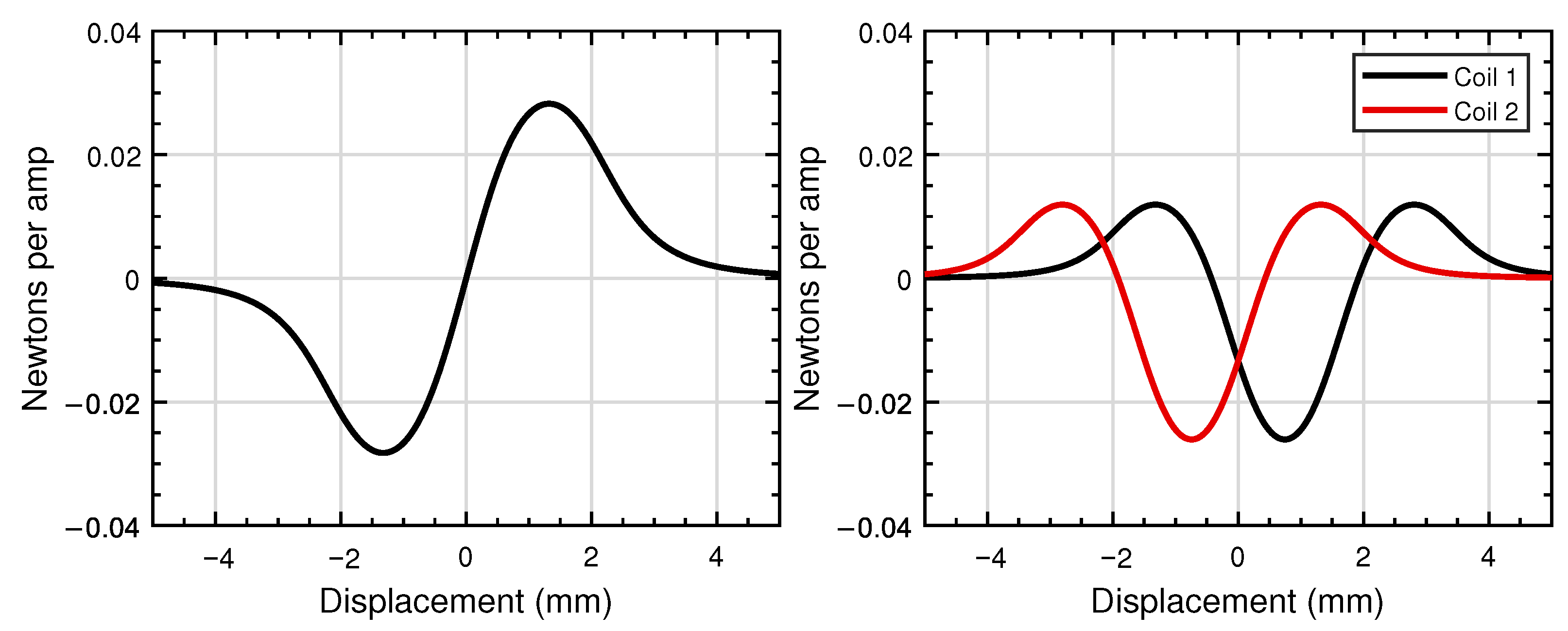
We have shown that the balance of aerodynamic and inertial power use in the system is the key to efficiency. In the absence of resonance, efficiency requires that any kinetic energy generated by the wing actuation system should be used to create aerodynamic force. Resonance in the form of elasticity in the wing or flapping mechanism can recover some kinetic energy at the expense of control, as the mechanism then takes on the characteristics of a flywheel that must be modulated to control the system. Low inertia and stiffness are very important, as it supports the per-wingbeat control enjoyed by dragonflies. We noted that flexibility can limit high speed flight by allowing aerostructural divergence.

5. Actuation

Examples of actuation for technological flapping wing systems have commonly centred around rotary electromagnetic actuators (motors), piezoelectric actuators, and dielectric elastomer actuators. While attempting to mimic biology with available technical solutions, these forms of actuation impose constraints that distance the engineered solution from the biological system. Rotary actuators require a transmission to convert rotation to reciprocation. This typically results in mechanisms with a fixed flapping amplitude, where the motor rotation rate controls flapping frequency. Each element in the drive train has rotational inertia, limiting the rate of change of the fixed flapping amplitude. A limited stroke angle and a limited ability to change rate quickly indicate limited control options. Although some success has been achieved with rotational systems, they are so far removed from the way a dragonfly is actuated that further analysis is not useful when considering a biomimetic design [102,103,104,105].
The use of servo actuation, which couples the wing rotation to a motor through a gearbox, has become popular and has demonstrated liftoff capability [106,107]. Due to the large torques required to generate flapping motion, the small motors require a reduction gearbox to amplify the torque at the cost of increasing the rotor speed. This increases the inertial load of each wing beat, resulting in a return spring to improve efficiency and allow the system to operate around resonance. This system’s limitation is incorporating a large enough return spring without exceeding the gearbox maximum strength. We have already shown that high inertia is a very limiting situation.
Piezoelectric actuators have restricted operational bandwidth, requiring them to be used at their resonant frequency for high efficiency and power density. This also means that the change of operating point to produce more or less power comes at a high price in efficiency [108]. The necessity to operate piezo and electroactive polymer actuators at high voltages comes with additional complexity of control and power electronics. Often, systems under test are tethered, allowing a craft to achieve liftoff without fully addressing the question of drive electronics. The need to generate a high voltage source from a low voltage source costs substantial mass and adds inefficiency. There is a substantial gap between the state of the art of these actuators and a viable flying system.
Our analysis will focus on linear electric motors, the simplest case of which is a solenoid. The electrical requirements of a coil-based actuator are vastly different to that of a piezoelectric actuator. Linear electric motors can be designed to operate at the voltages of common batteries. The power electronics design is also simplified with the use of a simple solid state H-bridge. This converts the DC supply to an AC source, which can be used to control the reciprocation of the actuator. The losses inside the H-bridge transistors are proportional to the resistance of the gates used, which are typically low. However, due to the dominance of ohmic losses in the actuators, and their low impedance, the losses across the gates will be significant.
Insects actuate their wings using muscles that act either directly on the wing base or indirectly by deforming the thoracic exoskeleton [109]. Indirect actuation is found in insects that use asymmetrical flight muscles, allowing them to flap at higher frequencies but with elasticity tuned to improve efficiency [110]. Odonata have a direct connection to symmetrical flight muscles, causing them to flap more slowly but with more control over the entire flapping cycle.
A direct actuation electromechanical system weighing 4.0 g was developed using magnets as a “virtual spring” to allow for high frequency flapping at resonance [111]. This system was capable of lift-off with a lift-to-weight ratio of 1.25; however, this system was uncontrolled [112]. Attempts to use reciprocating electromagnetic actuators to achieve liftoff have been successful while requiring significant electrical power [113]. Although the electrical performance of this actuator was low, it provides a compelling analog to biological muscles and can be designed, tested, and iterated using existing industrial equipment and controlled with simple electronics.
Actuator configurations have typically consisted of a single magnet and coil as shown in Figure 13, left. Our recent work has looked at the performance of actuators with multiple magnets and coils shown in Figure 13, right [114]. These actuators utilise two magnets with axially opposing magnetic fields. The additional coil provides further displacement while reducing peak currents that cause high ohmic losses. The additional magnet provides a higher peak magnetic field, further reducing input current for a fixed force.

5.1. Actuator Modelling

A linear electromagnetic actuator consists of only two major components, a coil of conductive wire and a permanent magnet. When the field of the magnet interacts with the magnetic field of the coil, the actuator generates a force. The force of the actuators can be estimated with an integral model of the actuator adapted from Furlani and Song [115,116] as demonstrated by us in [117]. Their force profile is characterised by
K f ( z ) = A B r B z ( z ) μ 0
where B r is the remnant field of the magnet, B z ( z ) is the magnetic field produced by the coil at displacement z, A = π M d 2 / 4 , and μ 0 is the permeability of free space. The magnetic field of the coil can be determined by taking the integral of the current loops of the coil along its axial length [115,116], (18)
B z ( z ) = 0 L D 1 2 D 2 2 μ o N i r 2 2 π ( r 2 + z 2 ) 3 / 2 d r d z
B z ( z ) = μ 0 N i 2 L ( D 1 D 2 ) ( L + 2 z ) ln α 1 + μ 0 N i 2 L ( D 1 D 2 ) ( L 2 z ) ln α 2
where
α 1 = D 2 + D 2 2 + ( L + 2 z ) 2 D 1 + D 1 2 + ( L + 2 z ) 2
α 2 = D 2 + D 2 2 + ( L 2 z ) 2 D 1 + D 1 2 + ( L 2 z ) 2
These equations can be used to calculate the force profile of the actuators presented in Figure 13. Figure 14, left, shows the force profile of a 58 mg actuator when the coil current is set to one amp, allowing the force profile to be demonstrated in newtons per amp over the displacement of the magnet relative to the coil. To increase the force output, the actuator would require an increased input current. The losses in the coils, however, are proportional to the square of the current, causing significant losses when high forces are required. A limitation of using a single coil stems from the force profiles crossing zero newtons per amp. Thus, a narrow operating range is required to maintain control, leaving some of the magnetic field unused. Changing to a dual magnet actuator increases the peak force that can be generated per amp. Shown on the right in Figure 14 is the force profile of a two-magnet and two-coil actuator of the same total mass, as the actuator is shown on the left in Figure 14. The resulting force peak is reduced, yet displacement is larger.
We demonstrated that the performance of linear electromagnetic actuators was reduced due to operating significantly above the natural frequency of the mechanism [117]. Tuning this system reduced the power consumption by a factor of 7, from 15 kW/kg [113] (relative to the mass of the craft) to 2 kW/kg. Further modifications of the actuator shown in [114] have demonstrated that, for a fixed mass, an improved design in conjunction with operating at the natural frequency of the system can bring the power-to-weight ratio to between 910 and 260 W/kg. Resonant linear electromagnetic actuators can achieve an efficiency of over 15% at the milligram scale, equivalent to Drosophila melanogaster flight muscles, where power output is approximately 60 W/kg for sustained flight with muscle efficiency of around 10% [118].
The argument is illustrated in the approach taken in [119], where the fundamental assumption on wing design is that the operating frequency is the natural frequency of the wing actuation system. This inevitably results in examples where wings with higher inertia can perform better than lower inertia wings [120], which is evidence of conflicting requirements. Electromagnetic actuators allow for the choice to pursue the same avenue of high stiffness mechanisms tuned for resonant operations. However, taking inspiration from nature drives the development of stiff, light wings that reduce the reliance on resonance to broaden the efficient operating range and allow for precise control.

5.2. Lessons from Actuators

A MAV designed to use the same path to efficient and powerful flight as the dragonfly might be able to use electromechanical actuators that have a large degree of design freedom, minimal transmission losses, low inertia, and very modest electronics requirements. We have established both theoretically and experimentally that performance comparable to insect muscle is attainable, both for efficiency and force development.
No studies have been done with wings of the same weight and stiffness as dragonfly wings. Most artificial wings are around an order of magnitude heavier. The weight difference in these artificial wings dramatically changes the balance of power consumption in the system, tilting them heavily towards needing resonance for efficiency, thus diverging from the dragonfly biological exemplar in a fundamental way.

6. Discussion

The dragonfly is one part of the solution space for making a flapping wing drone. It happens to be apparently aerodynamically efficient and maneuverable, but other factors such as cost and complexity may make it less desirable than other solutions. We will reduce what we know about the solution, drawing from the lessons of each system analysed.
The wings are to be light and stiff, to the limit of available technology, ideally lighter than 2% of the weight of the craft. This maximises the amount of instantaneous control that the actuators have over the wings and increases the speed at which aerostructural divergence limits flight. The wings should have high aerodynamic performance through a combination of a two-dimensional planform, for example a high aspect ratio, and three-dimensional surface features that produce lift and retain an attached flow to high angles of attack. This combination of features leads to a heavily damped, low-inertia load on the actuators.
The actuators managing this wing should operate across a broad range of frequencies without a loss of efficiency. The low residual kinetic energy in the system means that the modulation of individual wing beats becomes achievable, including intermittent flapping, variations in amplitude and frequency, and variations in force profiles within a wing beat. These features indicate an actuator with a substantial scope for control, a direct drive, low inertia, and minimal elastic behaviour at the frequencies in question.
The drone could serve multiple functions, including carrying and dropping payload. It might consume fuel from a fuel cell (the dragonfly analogue is fat deposits). In an outdoor environment, it might become wet. These events will cause shifts in the centre of gravity that need to be compensated with energetically expensive aerodynamic moments from the wings, or an internal shift of mass to re-balance. Flying systems should not carry dead weight for balance (although many do, including many fixed wing drones); yet, perhaps if some vital functions and fuel were formed into a high moment beam with articulation from near the centre of mass, rebalance could be rapidly achieved with little additional weight. Having made such a mechanism, it might as well be used for manoeuvre and for reasserting stability on demand by moving the centre of gravity ahead of the aerodynamic centre. This structure might look like an abdomen. Other concepts might be devised, but it seems very attractive and simple compared to other options.
There is clearly another end of the flapping wing drone solution space (and no doubt a multidimensional space in between). Possibly a smaller “fly-like” solution has wings that are heavier and less efficient, either by design or as a function of scale. The mechanisms might rely on resonance to recover kinetic energy from the wings and might exploit flexible parts of the fuselage to store energy in an elastic form. An increased use of low R e aerodynamic energy recapture by wings might be necessary for flight to be possible. Higher wing beat frequencies would compensate for the lack of individual wing control. Wing actuation might be indirect and in a narrow frequency band. The actuated abdomen might remain because of the need for weight shift for steering because of the reduced control over the resonant wing mechanism. This solution would have lower performance and a narrower repertoire of flight modes but would have fewer parts.
Flapping wings for lift and propulsion appear to lead naturally to biomimetic outcomes. Some features that might appear whimsical, such as venation patterns on wings and an articulated aft section, might be a practical necessity in future designs. This might reflect an ingrained influence from the biological systems that surround us. Certainly flapping wing drone designers could consider what sort of solution they are creating and look carefully at the features of existing biological examples. Figure 15 is intended to provoke thought, considering all issues and all roles; if not this, then what?

7. Conclusions

Studies of insects have revealed the principles of most of the systems they use for flight. From this knowledge, it appears that a drone capable of dragonfly-like performance using flapping wings and capable of flexible missions is very likely to have most of the external features of the dragonfly. The wings will be highly optimised with stiff structures and advanced aerodynamic optimisations. The beating of the wings is likely to be directly and individually driven by tuned actuators, also with very little flexibility or inertia. To manage the variations in balance that occur from changes over time or between configurations, a means is required to dynamically alter balance, with the equivalent of an abdomen serving this purpose.
We have shown through analysis of the principles of insect flight systems that future drones that attempt to harness some of the coveted characteristics of dragonflies are likely to be constrained to use many of the same solutions and even their anatomical features.

Author Contributions

Conceptualisation, J.C.; Data curation, N.C.; Formal analysis, Nasim Chitsaz, B.M., T.O., J.-M.K., and E.A.; Funding acquisition, J.C.; Investigation, N.C., B.M., T.O., J.-M.K., and T.M.; Methodology, J.C.; Project administration, T.M.; Resources, J.C. and J.-M.K.; Supervision, J.C. and E.A.; Writing—original draft, J.C.; Writing—review & editing, J.C., N.C., B.M., T.O., J.-M.K., T.M., and E.A. All authors have read and agreed to the published version of the manuscript.

Funding

N.C. and B.M. were supported by the Australian Government Research Training Program (RTP) Scholarship. T.O. was supported by the Australian Government Research Training Program international (RTPi) scholarship. N.C. was supported by the William T. Southcott Scholarship from the University of South Australia.

Institutional Review Board Statement

Not applicable.

Informed Consent Statement

Not applicable.

Data Availability Statement

The 3D geometry of dragonfly wings in zipped files are available at Dryad, https://0-doi-org.brum.beds.ac.uk/10.5061/dryad.6t1g1jwtt (accessed on 27 March 2021). Each zipped file includes the wing models of one species of Odonata.

Acknowledgments

We would like to thank the South Australian Museum, Adelaide, and the South Australian Research and Development Institute (SARDI) Entomology Science Program for granting access to their collections of dragonflies used in this study.

Conflicts of Interest

The authors declare no conflict of interest.

References

  1. Corbet, P.S. Dragonflies: Behaviour and Ecology of Odonata; Harley Books: Manunda, Australia, 1999. [Google Scholar]
  2. Silsby, J. Dragonflies of the World; CSIRO Publishing: Melbourne, Australia, 2001. [Google Scholar]
  3. Chahl, J.; Dorrington, G.; Premachandran, S.; Mizutani, A. The dragonfly flight envelope and its application to micro uav research and development. IFAC Proc. Vol. 2013, 46, 231–234. [Google Scholar] [CrossRef]
  4. Marden, J.H. Maximum lift production during takeoff in flying animals. J. Exp. Biol. 1987, 130, 235–258. [Google Scholar]
  5. Olberg, R.M. Visual control of prey-capture flight in dragonflies. Curr. Opin. Neurobiol. 2012, 22, 267–271. [Google Scholar] [CrossRef]
  6. Olberg, R.; Worthington, A.; Venator, K. Prey pursuit and interception in dragonflies. J. Comp. Physiol. A 2000, 186, 155–162. [Google Scholar] [CrossRef]
  7. Combes, S.; Rundle, D.; Iwasaki, J.; Crall, J.D. Linking biomechanics and ecology through predator-prey interactions: Flight performance of dragonflies and their prey. J. Exp. Biol. 2012, 215, 903–913. [Google Scholar] [CrossRef] [Green Version]
  8. Mizutani, A.; Chahl, J.S.; Srinivasan, M.V. Active motion camouflage by dragonflies. Nature 2003, 423, 604. [Google Scholar] [CrossRef]
  9. Carey, N.E.; Ford, J.J.; Chahl, J.S. Biologically inspired guidance for motion camouflage. In Proceedings of the 2004 5th Asian Control Conference (IEEE Cat. No. 04EX904), Melbourne, VIC, Australia, 20–23 July 2004; Volume 3, pp. 1793–1799. [Google Scholar]
  10. Wakeling, J.; Ellington, C. Dragonfly flight. I. Gliding flight and steady-state aerodynamic forces. J. Exp. Biol. 1997, 200, 543–556. [Google Scholar]
  11. Azuma, A.; Watanabe, T. Flight performance of a dragonfly. J. Exp. Biol. 1988, 137, 221–252. [Google Scholar]
  12. Newman, B. Model test on a wing section of a dragonfly. In Scale Effects in Animal Locomotion; Academic Press: London, UK, 1977; pp. 445–477. [Google Scholar]
  13. May, M.L. A critical overview of progress in studies of migration of dragonflies (Odonata: Anisoptera), with emphasis on North America. J. Insect Conserv. 2013, 17, 1–15. [Google Scholar] [CrossRef] [Green Version]
  14. Scorer, R. The nature of convection as revealed by soaring birds and dragonflies. Q. J. R. Meteorol. Soc. 1954, 80, 68–77. [Google Scholar] [CrossRef]
  15. Purcell, E.M. The efficiency of propulsion by a rotating flagellum. Proc. Natl. Acad. Sci. USA 1997, 94, 11307–11311. [Google Scholar] [CrossRef] [Green Version]
  16. Srinivasan, M.V.; Chahl, J.S.; Weber, K.; Venkatesh, S.; Nagle, M.G.; Zhang, S.W. Robot navigation inspired by principles of insect vision. Robot. Auton. Syst. 1999, 26, 203–216. [Google Scholar] [CrossRef]
  17. Cayley, G. On Aërial Navigation. Annu. Rep. Aeronaut. Soc. Great Br. 1876, 11, 60–94. [Google Scholar] [CrossRef] [Green Version]
  18. Lilienthal, O. Practical experiments for the development of human flight. In The Aeronautical Annual; W.B. Clarke Company: San Jose, CA, USA, 1896; pp. 7–20. [Google Scholar]
  19. McFarland, M.W.; Renstrom, A.G. The Papers of Wilbur and Orville Wright. Q. J. Curr. Acquis. 1950, 7, 22–34. [Google Scholar]
  20. Stange, G. The Ocellar Component of Flight Equilibrium Control in Dragonflies. J. Comp. Physiol. 1981, 141, 335–347. [Google Scholar] [CrossRef]
  21. Chahl, J.; Mizutani, A. Biomimetic attitude and orientation sensors. Sens. J. IEEE 2012, 12, 289–297. [Google Scholar] [CrossRef]
  22. Stange, G.; Howard, J. An Ocellar Dorsal Light Response in a Dragonfly. J. Exp. Biol. 1979, 83, 351–355. [Google Scholar]
  23. Stange, G.F.; Stowe, S.; Chahl, J.S.; Massaro, A. Anisotropic Imaging in the Dragonfly Median Ocellus: A Matched Filter for Horizon Detection. J. Comp. Physiol. 2002, 188, 455–467. [Google Scholar]
  24. Thakoor, S.; Morookian, J.M.; Chahl, J.; Hine, B.; Zornetzer, S. BEES: Exploring mars with bioinspired technologies. Computer 2004, 37, 38–47. [Google Scholar] [CrossRef]
  25. Salami, E.; Ward, T.A.; Montazer, E.; Ghazali, N.N.N. A review of aerodynamic studies on dragonfly flight. Proc. Inst. Mech. Eng. Part J. Mech. Eng. Sci. 2019, 233, 6519–6537. [Google Scholar] [CrossRef]
  26. Sane, S.P. The aerodynamics of insect flight. J. Exp. Biol. 2003, 206, 4191–4208. [Google Scholar] [CrossRef] [Green Version]
  27. Cheng, X.; Sun, M. Very small insects use novel wing flapping and drag principle to generate the weight-supporting vertical force. arXiv 2018, arXiv:1807.05629. [Google Scholar] [CrossRef] [Green Version]
  28. Shyy, W.; Aono, H.; Kang, C.K.; Liu, H. An Introduction to Flapping Wing Aerodynamics; Cambridge University Press: Cambridge, UK, 2013; Volume 37. [Google Scholar]
  29. Kesel, A.B. Aerodynamic characteristics of dragonfly wing sections compared with technical aerofoils. J. Exp. Biol. 2000, 203, 3125–3135. [Google Scholar]
  30. Hu, Z.; McCauley, R.; Schaeffer, S.; Deng, X. Aerodynamics of dragonfly flight and robotic design. In Proceedings of the 2009 IEEE International Conference on Robotics and Automation, Kobe, Japan, 12–17 May 2009; pp. 3061–3066. [Google Scholar]
  31. Luo, Y.; He, G.; Liu, H.; Wang, Q.; Song, H. Aerodynamic Performance of Dragonfly Forewing—Hindwing Interaction in Gliding Flight; IOP Conference Series: Materials Science and Engineering; IOP Publishing: Bristol, UK, 2019; Volume 538, p. 012048. [Google Scholar]
  32. Hefler, C.; Noda, R.; Qiu, H.; Shyy, W. Aerodynamic performance of a free-flying dragonfly—A span-resolved investigation. Phys. Fluids 2020, 32, 041903. [Google Scholar] [CrossRef]
  33. Bunget, G.; Seelecke, S. BATMAV: A biologically inspired micro-air vehicle for flapping flight: Kinematic modeling. In Active and Passive Smart Structures and Integrated Systems 2008; International Society for Optics and Photonics: Bellingham, WA, USA, 2008; Volume 6928, p. 69282F. [Google Scholar]
  34. Chitsaz, N.; Marian, R.; Chahl, J. Experimental method for 3D reconstruction of Odonata wings (methodology and dataset). PLoS ONE 2020, 15, e0232193. [Google Scholar] [CrossRef]
  35. Chitsaz, N.; Chahl, J. Current knowledge of corrugated dragonfly wing structures and future measurement methodology. In Proceedings of the AIAC18: 18th Australian International Aerospace Congress (2019): HUMS—11th Defence Science and Technology (DST) International Conference on Health and Usage Monitoring (HUMS 2019): ISSFD—27th International Symposium on Space Flight Dynamics (ISSFD), Melbourne, Australia, 24–28 February 2019; Engineers Australia, Royal Aeronautical Society: Melbourne, Australia, 2019; pp. 412–417. [Google Scholar]
  36. Oniga, E.; Chirilă, C.; Stătescu, F. Accuracy assessment of a complex building 3d model reconstructed from images acquired with a low-cost Uas. Int. Arch. Photogramm. Remote. Sens. Spat. Inf. Sci. 2017, 42, 551. [Google Scholar] [CrossRef] [Green Version]
  37. Chitsaz, N.; Marian, R.; Chitsaz, A.; Chahl, J.S. Parametric and Statistical Study of the Wing Geometry of 75 Species of Odonata. Appl. Sci. 2020, 10, 5389. [Google Scholar] [CrossRef]
  38. Rees, C.J. Form and function in corrugated insect wings. Nature 1975, 256, 200–203. [Google Scholar] [CrossRef]
  39. Rudolph, R. Aerodynamic properties of Libellula quadrimaculata L.(Anisoptera: Libellulidae), and the flow around smooth and corrugated wing section models during gliding flight. Odonatologica 1978, 7, 49–58. [Google Scholar]
  40. Okamoto, M.; Yasuda, K.; Azuma, A. Aerodynamic characteristics of the wings and body of a dragonfly. J. Exp. Biol. 1996, 199, 281–294. [Google Scholar]
  41. Gaurav, S.; Jain, K.K. Numerical investigation of fluid flow and aerodynamic performance of a dragonfly wing section for micro air vehicles (MAVs) application. Int. J. Innovat. Scient. Res. 2014, 92, 285–292. [Google Scholar]
  42. Flint, T.; Jermy, M.; New, T.; Ho, W. Computational study of a pitching bio-inspired corrugated airfoil. Int. J. Heat Fluid Flow 2017, 65, 328–341. [Google Scholar] [CrossRef]
  43. Xiang, J.; Du, J.; Li, D.; Liu, K. Aerodynamic performance of the locust wing in gliding mode at low Reynolds number. J. Bionic Eng. 2016, 13, 249–260. [Google Scholar] [CrossRef]
  44. Khurana, M.; Chahl, J. A computational fluid dynamic study of a bioinspired corrugated aerofoil for micro air vehicles. In Proceedings of the AIAC15: 15th Australian International Aerospace Congress, Melbourne, Australia, 25–28 February 2013; p. 126. [Google Scholar]
  45. Kok, J.; Chahl, J. Optimization of the leading edge segment of a corrugated wing. In Bioinspiration, Biomimetics, and Bioreplication 2014; International Society for Optics and Photonics: San Diego, CA, USA, 2014; p. 905517. [Google Scholar]
  46. Meng, X.G.; Sun, M. Aerodynamic effects of wing corrugation at gliding flight at low Reynolds numbers. Phys. Fluids 2013, 25, 071905. [Google Scholar] [CrossRef]
  47. Chitsaz, N.; Siddiqui, K.; Marian, R.; Chahl, J. An experimental study of the aerodynamics of micro corrugated wings at low Reynolds number. Exp. Therm. Fluid Sci. 2021, 121, 110286. [Google Scholar] [CrossRef]
  48. Heinrich, B.; Casey, T.M. Heat transfer in dragonflies:‘fliers’ and ‘perchers’. J. Exp. Biol. 1978, 74, 17–36. [Google Scholar]
  49. Dyhr, J.P.; Cowan, N.J.; Colmenares, D.J.; Morgansen, K.A.; Daniel, T.L. Autostabilizing airframe articulation: Animal inspired air vehicle control. In Proceedings of the 2012 IEEE 51st IEEE Conference on Decision and Control (CDC), Maui, HI, USA, 10–13 December 2012; pp. 3715–3720. [Google Scholar]
  50. Jagnandan, K.; Higham, T.E. Lateral movements of a massive tail influence gecko locomotion: An integrative study comparing tail restriction and autotomy. Sci. Rep. 2017, 7, 1–8. [Google Scholar] [CrossRef] [PubMed] [Green Version]
  51. Kohut, N.J. Inertial and Aerodynamic Tail Steering of a Meso-Scale Legged Robot; University of California: Berkeley, CA, USA, 2013. [Google Scholar]
  52. Patel, A. Understanding the Motions of the Cheetah Tail Using Robotics. Ph.D. Thesis, University of Cape Town, Cape Town, South Africa, 2015. [Google Scholar]
  53. Camhi, J.M. Yaw-correcting postural changes in locusts. J. Exp. Biol. 1970, 52, 519–531. [Google Scholar]
  54. Camhi, J.M. Sensory control of abdomen posture in flying locusts. J. Exp. Biol. 1970, 52, 533–537. [Google Scholar]
  55. Götz, K.G.; Hengstenberg, B.; Biesinger, R. Optomotor control of wing beat and body posture in Drosophila. Biological Cybern. 1979, 35, 101–112. [Google Scholar] [CrossRef]
  56. Zanker, J.M. How does lateral abdomen deflection contribute to flight control ofDrosophila melanogaster? J. Comp. Physiol. A 1988, 162, 581–588. [Google Scholar] [CrossRef]
  57. Zanker, J. On the mechanism of speed and altitude control in Drosophila melanogaster. Physiol. Entomol. 1988, 13, 351–361. [Google Scholar] [CrossRef]
  58. Luu, T.; Cheung, A.; Ball, D.; Srinivasan, M.V. Honeybee flight: A novel ‘streamlining’response. J. Exp. Biol. 2011, 214, 2215–2225. [Google Scholar] [CrossRef] [Green Version]
  59. Hinterwirth, A.J.; Daniel, T.L. Antennae in the hawkmoth Manduca sexta (Lepidoptera, Sphingidae) mediate abdominal flexion in response to mechanical stimuli. J. Comp. Physiol. A 2010, 196, 947–956. [Google Scholar] [CrossRef] [PubMed]
  60. Dyhr, J.P.; Morgansen, K.A.; Daniel, T.L.; Cowan, N.J. Flexible strategies for flight control: An active role for the abdomen. J. Exp. Biol. 2013, 216, 1523–1536. [Google Scholar] [CrossRef] [PubMed] [Green Version]
  61. Rüppell, G.; Hilfert-Rüppell, D.; Schneider, B.; Dedenbach, H. On the firing line—Interactions between hunting frogs and Odonata. Int. J. Odonatol. 2020, 23, 1–19. [Google Scholar] [CrossRef]
  62. Sun, M.; Xiong, Y. Dynamic flight stability of a hovering bumblebee. J. Exp. Biol. 2005, 208, 447–459. [Google Scholar] [CrossRef] [PubMed] [Green Version]
  63. Mou, X.; Sun, M. Dynamic flight stability of a model hoverfly in inclined-stroke-plane hovering. J. Bionic Eng. 2012, 9, 294–303. [Google Scholar] [CrossRef]
  64. Liang, B.; Sun, M. Dynamic flight stability of a hovering model dragonfly. J. Theor. Biol. 2014, 348, 100–112. [Google Scholar] [CrossRef]
  65. Cheng, C.; Wu, J.; Zhang, Y.; Li, H.; Zhou, C. Aerodynamics and dynamic stability of micro-air-vehicle with four flapping wings in hovering flight. Adv. Aerodyn. 2020, 2, 1–19. [Google Scholar] [CrossRef] [Green Version]
  66. Jang, J.; Tomlin, C. Longitudinal stability augmentation system design for the DragonFly UAV using a single GPS receiver. In Proceedings of the AIAA Guidance, Navigation, and Control Conference and Exhibit, Austin, TX, USA, 11–14 August 2003; p. 5592. [Google Scholar]
  67. Couceiro, M.S.; Ferreira, N.; Tenreiro Machado, J. Modeling and control of a dragonfly-like robot. J. Control. Sci. Eng. 2010. [Google Scholar] [CrossRef] [Green Version]
  68. Nguyen, Q.V.; Chan, W.L.; Debiasi, M. Design, fabrication, and performance test of a hovering-based flapping-wing micro air vehicle capable of sustained and controlled flight. In Proceedings of the IMAV 2014: International Micro Air Vehicle Conference and Competition 2014, Delft, The Netherlands, 12–15 August 2014; Delft University of Technology: Delft, The Netherlands, 2014. [Google Scholar]
  69. Kok, J.M. Active Wing Control in a Dragonfly-Inspired Micro Air Vehicle. 2016. Available online: https://find.library.unisa.edu.au/primo-explore/fulldisplay?vid=UNISA&search_scope=All_Resources&docid=UNISA_ALMA11153485500001831 (accessed on 16 September 2020).
  70. Du, C.; Xu, J.; Zheng, Y. Modeling and control of a dragonfly-like micro aerial vehicle. Adv. Robot. Autom. 2015, 2, 2. [Google Scholar]
  71. Ogunwa, T.; McIvor, B.; Jumat, N.A.; Abdullah, E.; Chahl, J. Longitudinal Actuated Abdomen Control for Energy Efficient Flight of Insects. Energies 2020, 13, 5480. [Google Scholar] [CrossRef]
  72. Zipfel, P.H. Modeling and Simulation of Aerospace Vehicle Dynamics; American Institute of Aeronautics and Astronautics: Washington, DC, USA, 2007. [Google Scholar]
  73. Constrained Nonlinear Optimization Algorithms—MATLAB & Simulink—MathWorks. Available online: https://au.mathworks.com/help/optim/ug/constrained-nonlinear-optimization-algorithms.html (accessed on 16 September 2020).
  74. MATLAB. 9.7.0.1190202 (R2019b); The MathWorks Inc.: Natick, MA, USA, 2019.
  75. Alexander, D.E. Wind tunnel studies of turns by flying dragonflies. J. Exp. Biol. 1986, 122, 81–98. [Google Scholar] [PubMed]
  76. Shaw, R.L. Fighter Combat. In Tactics Maneuvering; Naval Institute Press: Annapolis, MD, USA, 1985. [Google Scholar]
  77. Dantsker, O.D.; Theile, M.; Caccamo, M. A High-Fidelity, Low-Order Propulsion Power Model for Fixed-Wing Electric Unmanned Aircraft. In Proceedings of the 2018 AIAA/IEEE Electric Aircraft Technologies Symposium (EATS), Cincinnati, OH, USA, 9–11 July 2018; pp. 1–16. [Google Scholar]
  78. Nickel, K.; Wohlfahrt, M. Tailless Aircraft in Theory and Practice; Hodder Education: London, UK, 1994. [Google Scholar]
  79. Kok, J.; Chahl, J. Systems-level analysis of resonant mechanisms for flapping-wing flyers. J. Aircr. 2014, 51, 1833–1841. [Google Scholar] [CrossRef]
  80. Alexander, D.E. Unusual phase relationships between the forewings and hindwings in flying dragonflies. J. Exp. Biol. 1984, 109, 379–383. [Google Scholar]
  81. Sviderskiĭ, V.; Plotnikova, S.; Gorelkin, V. Structural-functional peculiarities of wing appatatus of insects that have and do not have maneuver flight. Zhurnal Evoliutsionnoĭ Biokhimii Fiziologii 2008, 44, 545. [Google Scholar]
  82. Ruppell, G. Kinematic analysis of symmetrical flight manoeuvres of Odonata. J. Exp. Biol. 1989, 144, 13–42. [Google Scholar]
  83. Wang, Z.J. The role of drag in insect hovering. J. Exp. Biol. 2004, 207, 4147–4155. [Google Scholar] [CrossRef] [Green Version]
  84. Wang, Z.J. Dissecting insect flight. Annu. Rev. Fluid Mech. 2005, 37, 183–210. [Google Scholar] [CrossRef] [Green Version]
  85. Wood, R.J. The first takeoff of a biologically inspired at-scale robotic insect. Robot. IEEE Trans. 2008, 24, 341–347. [Google Scholar] [CrossRef]
  86. Sahai, R.; Galloway, K.C.; Wood, R.J. Elastic element integration for improved flapping-wing micro air vehicle performance. IEEE Trans. Robot. 2012, 29, 32–41. [Google Scholar] [CrossRef]
  87. Baek, S.S.; Ma, K.Y.; Fearing, R.S. Efficient resonant drive of flapping-wing robots. In Proceedings of the IROS 2009. IEEE/RSJ International Conference on Intelligent Robots and Systems, St. Louis, MO, USA, 11–15 October 2009; pp. 2854–2860. [Google Scholar]
  88. Fung, Y.C. An Introduction to the Theory of Aeroelasticity; Includes Index; Wiley: New York, NY, USA, 1955; 490p. [Google Scholar]
  89. Sun, M.; Lan, S.L. A computational study of the aerodynamic forces and power requirements of dragonfly (Aeschna juncea) hovering. J. Exp. Biol. 2004, 207, 1887–1901. [Google Scholar] [CrossRef] [Green Version]
  90. Azuma, A.; Azuma, S.; Watanabe, I.; Furuta, T. Flight mechanics of a dragonfly. J. Exp. Biol. 1985, 116, 79–107. [Google Scholar]
  91. May, M.L. Dragonfly flight: Power requirements at high speed and acceleration. J. Exp. Biol. 1991, 158, 325–342. [Google Scholar]
  92. Kok, J.; Chahl, J. A low-cost simulation platform for flapping wing MAVs. In SPIE Smart Structures and Materials+ Nondestructive Evaluation and Health Monitoring; International Society for Optics and Photonics: San Diego, CA, USA, 2015; p. 94290L. [Google Scholar]
  93. Kok, J.; Lau, G.; Chahl, J. On the Aerodynamic Efficiency of Insect-Inspired Micro Aircraft Employing Asymmetrical Flapping. J. Aircr. 2016, 1–11. [Google Scholar] [CrossRef]
  94. Lentink, D.; Jongerius, S.R.; Bradshaw, N.L. The scalable design of flapping micro-air vehicles inspired by insect flight. In Flying Insects and Robots; Springer: Berlin/Heidelberg, Germany, 2009; pp. 185–205. [Google Scholar]
  95. Karpelson, M.; Whitney, J.P.; Wei, G.Y.; Wood, R.J. Energetics of flapping-wing robotic insects: Towards autonomous hovering flight. In Proceedings of the 2010 IEEE/RSJ International Conference on Intelligent Robots and Systems (IROS), Taipei, Taiwan, 18–22 October 2010; pp. 1630–1637. [Google Scholar]
  96. Ratti, J.; Vachtsevanos, G. A biologically-inspired micro aerial vehicle. J. Intell. Robot. Syst. 2010, 60, 153–178. [Google Scholar] [CrossRef]
  97. Ratti, J.; Jones, E.; Vachtsevanos, G. Fixed frequency, variable amplitude (FiFVA) actuation systems for micro aerial vehicles. In Proceedings of the 2011 IEEE International Conference on Robotics and Automation (ICRA), Shanghai, China, 9–13 May 2011; pp. 165–171. [Google Scholar]
  98. Ratti, J.; Vachtsevanos, G. Inventing a biologically inspired, energy efficient micro aerial vehicle. J. Intell. Robot. Syst. 2012, 65, 437–455. [Google Scholar] [CrossRef]
  99. Roll, J.A. Bio-Inspired Flapper with Electromagnetic Actuation. Ph.D. Thesis, Purdue University, West Lafayette, IN, USA, 2012. [Google Scholar]
  100. Finio, B.M.; Wood, R.J. Open-loop roll, pitch and yaw torques for a robotic bee. In Proceedings of the 2012 IEEE/RSJ International Conference on Intelligent Robots and Systems (IROS), Vilamoura, Algarve, 7–12 October 2012; pp. 113–119. [Google Scholar]
  101. Karpelson, M.; Wei, G.Y.; Wood, R.J. Milligram-scale high-voltage power electronics for piezoelectric microrobots. In Proceedings of the ICRA’09. IEEE International Conference on Robotics and Automation, Kobe, Japan, 12–17 May 2009; pp. 2217–2224. [Google Scholar]
  102. De Croon, G.; De Clercq, K.; Ruijsink, R.; Remes, B.; De Wagter, C. Design, aerodynamics, and vision-based control of the DelFly. Int. J. Micro Air Veh. 2009, 1, 71–97. [Google Scholar] [CrossRef]
  103. Ristroph, L.; Childress, S. Stable hovering of a jellyfish-like flying machine. J. R. Soc. Interface 2014, 11, 20130992. [Google Scholar] [CrossRef] [Green Version]
  104. Palmer, J.L.; Jones, M.B.; Drobik, J. Design Elements of a Bio-Inspired Micro Air Vehicle. IFAC Proc. Vol. 2013, 46, 235–241. [Google Scholar] [CrossRef]
  105. Phan, H.V.; Kang, T.; Park, H.C. Design and stable flight of a 21 g insect-like tailless flapping wing micro air vehicle with angular rates feedback control. Bioinspir. Biomim. 2017, 12, 036006. [Google Scholar] [CrossRef] [PubMed]
  106. Campolo, D.; Azhar, M.; Lau, G.K.; Sitti, M. Can DC motors directly drive flapping wings at high frequency and large wing strokes? IEEE/ASME Trans. Mechatron. 2012, 19, 109–120. [Google Scholar] [CrossRef]
  107. Hines, L.; Campolo, D.; Sitti, M. Liftoff of a motor-driven, flapping-wing microaerial vehicle capable of resonance. IEEE Trans. Robot. 2014, 30, 220–232. [Google Scholar] [CrossRef]
  108. Steltz, E.; Avadhanula, S.; Fearing, R.S. High lift force with 275 Hz wing beat in MFI. In Proceedings of the 2007 IEEE/RSJ International Conference on Intelligent Robots and Systems, San Diego, CA, USA, 29 October–2 November 2007; pp. 3987–3992. [Google Scholar]
  109. Josephson, R.K. Comparative physiology of insect flight muscle. In Nature’s Versatile Engine: Insect Flight Muscle Inside and Out; Springer: Berlin/Heidelberg, Germany, 2006; pp. 34–43. [Google Scholar]
  110. Ellington, C.P. Power and efficiency of insect flight muscle. J. Exp. Biol. 1985, 115, 293–304. [Google Scholar]
  111. Roll, J.A.; Cheng, B.; Deng, X. An electromagnetic actuator for high-frequency flapping-wing microair vehicles. IEEE Trans. Robot. 2015, 31, 400–414. [Google Scholar] [CrossRef]
  112. Roll, J.A.; Bardroff, D.T.; Deng, X. Mechanics of a scalable high frequency flapping wing robotic platform capable of lift-off. In Proceedings of the 2016 IEEE International Conference on Robotics and Automation (ICRA), Stockholm, Sweden, 16–21 May 2016; pp. 4664–4671. [Google Scholar]
  113. Zou, Y.; Zhang, W.; Zhang, Z. Liftoff of an electromagnetically driven insect-inspired flapping-wing robot. IEEE Trans. Robot. 2016, 32, 1285–1289. [Google Scholar] [CrossRef]
  114. McIvor, B.A.; Ogunwa, T.T.; Chahl, J.S. Geometry of efficient Electromagnetic Linear actuators for flapping wing MAVs. Eng. Res. Express 2020, 2, 045027. [Google Scholar] [CrossRef]
  115. Furlani, E.P. Permanent Magnet and Electromechanical Devices: Materials, Analysis, and Applications; Academic Press: Cambridge, MA, USA, 2001. [Google Scholar]
  116. Song, C.W.; Lee, S.Y. Design of a solenoid actuator with a magnetic plunger for miniaturized segment robots. Appl. Sci. 2015, 5, 595–607. [Google Scholar] [CrossRef] [Green Version]
  117. McIvor, B.; Chahl, J. Energy efficiency of linear electromagnetic actuators for flapping wing micro aerial vehicles. Energies 2020, 13, 1075. [Google Scholar] [CrossRef] [Green Version]
  118. Lehmann, F.O.; Dickinson, M.H. The changes in power requirements and muscle efficiency during elevated force production in the fruit fly Drosophila melanogaster. J. Exp. Biol. 1997, 200, 1133–1143. [Google Scholar] [PubMed]
  119. Whitney, J.; Wood, R. Conceptual design of flapping-wing micro air vehicles. Bioinspir. Biomimetics 2012, 7, 036001. [Google Scholar] [CrossRef] [PubMed] [Green Version]
  120. Chen, Y.; Ma, K.; Wood, R.J. Influence of wing morphological and inertial parameters on flapping flight performance. In Proceedings of the 2016 IEEE/RSJ International Conference on Intelligent Robots and Systems (IROS), Daejeon, Korea, 9–14 October 2016; pp. 2329–2336. [Google Scholar]
Figure 1. An aircraft wing (a), a rotor (b), and a dragonfly wing (c), each highly optimised for its function.
Drones 05 00024 g001
Figure 2. The difference between the wing shapes of two large flying insects—a robber fly, Phellus piliferus (left), and a dragonfly, Libellula pulchella (right)—can be described, to a first order approximation, by aspect ratio.
Drones 05 00024 g002
Figure 3. Left: Museum specimens are fragile and cannot be removed from their cases. Intact and damaged specimens are shown. Right: A dragonfly wing being scanned by a robotic photogrammetry assistant at the South Australian Museum [34].
Drones 05 00024 g003
Figure 4. Models of wings reconstructed using an automated photogrammetry technique for measuring insect wing geometry [34].
Drones 05 00024 g004
Figure 5. Reconstructed aerofoils of Aeshna cyanea (Müller, 1764) FW [29].
Drones 05 00024 g005
Figure 6. Comparison of span-wise vorticity (color bar) and instantaneous velocity field around the reconstructed FW and HW (left) and flat FW and HW (right), at R e = 3 × 10 3 and α = 10 . The laser light sheet incident from the top side created a shadow underneath the wing.
Drones 05 00024 g006
Figure 7. Comparison of aerodynamic lift and drag measurements of corrugated and flat wings at α = 10 and R e = 22 × 10 3 (left) and pressure distribution from numerical and experimental results of corrugated wing at α = 10 and R e = 6 × 10 3 (right).
Drones 05 00024 g007
Figure 8. Scanning electron microscope image of a Neurobasis daviesi wing.
Drones 05 00024 g008
Figure 9. Definition of coordinate systems: Inertial (I), Body (B), and Tail (T).
Drones 05 00024 g009
Figure 10. Pull down flight simulation results.
Drones 05 00024 g010
Figure 11. Turning flight simulation results.
Drones 05 00024 g011
Figure 12. Response of two damped systems with and without elastic storage mechanisms to an instantaneous step input (Top). The aerodynamic forces are represented by a quadratic function. The dashed and solid lines represent systems with and without elastic storage, respectively. The damping force (Bottom) is the performance metric for determining the manoeuvrability of the system.
Drones 05 00024 g012
Figure 13. The force profile of a single magnet within a coil (left) and the force profile of a dual magnet within a coil (right).
Drones 05 00024 g013
Figure 14. The force profile of a single magnet within a coil (left) and the force of a two-magnet and two-coil actuator (right).
Drones 05 00024 g014
Figure 15. A whimsical 200 mm wingspan biomimetic dragonfly drone in flight. Large, directly driven, corrugated wings are as efficient as fixed wings on drones with a much larger wingspan. Direct actuation allows for exquisite control of hover, while being able to soar effortlessly on rising currents of air. The abdomen containing the fuel cell doubles as a rudder and ballast, allowing the vehicle to collect and deliver awkward unbalanced loads while flying on the efficient edge of instability.
Drones 05 00024 g015
Table 1. Aircraft model physical properties [71].
ParameterValueParameterValue
m B  (kg)0.325 m T  (kg)0.06
Body length, l B  (m)0.3Tail length, l T m a x  (m)0.4
Max. body diameter, d B m a x  (m)0.14Tail diameter, d T  (m)0.05
J x x b B  (kg m 2 )0.00187 b r e f  (m)1.4
J y y b B  (kg m 2 )0.01117 c r e f  (m)0.19434
J z z B B  (kg m 2 )0.00934S (m 2 )0.26865
c g b B  (m)[−0.064; 0; 0.003] A R P  (m)[0.025; 0; 0]
Table 2. Results for steady level flight trim conditions.
V 0  (m/s) H 0  (m) ρ jb x 0  (m) ρ tj x 0  (m) θ T 0 ( ) θ 0 ( ) δ e 0 ( ) T n 0  (N)
101000.2640.30−0.252−1.790.825
Publisher’s Note: MDPI stays neutral with regard to jurisdictional claims in published maps and institutional affiliations.

