
Lyapunov Stability of a Planar Vertical Take-Off and Landing Aircraft Exerting a Force in the Environment


1
CNRS UMR 7253 Heudiasyc, Université de Technologie de Compiègne, 60200 Compiègne, France
2
UMI-LAFMIA, CINVESTAV, Ciudad de Mexico 07360, Mexico
*
Author to whom correspondence should be addressed.
Drones 2022, 6(6), 144; https://0-doi-org.brum.beds.ac.uk/10.3390/drones6060144
Submission received: 29 April 2022
/
Revised: 3 June 2022
/
Accepted: 8 June 2022
/
Published: 11 June 2022
(This article belongs to the Special Issue Honorary Special Issue for Prof. Max F. Platzer)
Abstract
:This work proposes a simplified control method to stabilize the model of a nonlinear Planar Vertical Take-Off and Landing (PVTOL) system when a constant force is applied in the horizontal axis. Since the stability analysis is based on a Lyapunov function, exponential stability is guaranteed when the initial conditions fall inside a domain of attraction that is also specified. The performance of the suggested control algorithm is demonstrated using numerical simulations.
1. Introduction
PVTOL (Planar Vertical Take-Off and Landing) have been the subject of extensive research over the years. Multiple control techniques have been applied to these vehicles. For example, in (Aguilar-Ibañez, 2017) [1] a sliding mode controller is proposed. The altitude of the PVTOL is stabilized using feedback linearization technique. The sliding mode controller is used to stabilize the horizontal and angular variables. Another example is given in (Hernandez et al., 2020) [2] and (Aguilar-Ibañez et al., 2018) [3] where the Immersion and Invariance (I&I) control technique is used to design a controller that stabilizes the PVTOL aircraft system. The controller prioritizes control of the aircraft’s altitude over control of the lateral displacement. In (Aguilar-Ibañez et al., 2020) [4] an output-feedback regulation control law for a PVTOL based on the shaping of an energy function is introduced. To that purpose, a variant of the matching control energy approach is utilized to build the Lyapunov candidate function and the controller used to regulate the system. Finally, even the interaction between two PVTOL vehicles performing together an activity has been studied in (Escobar et al., 2020) [5] were the proposed method employs a decentralized control scheme based on the concept of passivity, in which no explicit communication occurs between agents, utilizing instead the physical link that exists between the agents and the load.
One of the attractive aspects of these PVTOL nonlinear systems is that they provide a first two-dimensional approach to the intricate dynamics of a three-dimensional quadrotor. PVTOL may face undesired interactions, such as turbulence in the environment. (Aguilar-Ibañez et al., 2019) [6] provides a robust controller for solving the trajectory-tracking control problem of a PVTOL in the presence of a crosswind where input–output feedback linearization and active disturbance rejection control techniques are used in the controller. Moreover, (Yao, 2021) [7] shows the trajectory tracking control problem of a PVTOL in the presence of position constraints and external disturbances. It is usual to task aerial vehicles with obstacle avoidance, as shown in (Kobayashi et al., 2009) [8] where the authors formulate the obstacle avoidance problem as an optimal control problem. It is also desirable in some instances to interact with an object, as long as it is under control. The interaction of a PVTOL with an object through the application of a controlled force is a subject being researched for a variety of applications where contact with the environment is required.
The subject of modeling and control of a specific configuration of Ducted-Fan Aerial Vehicle (DFAV) is addressed in (Marconi et al., 2008) [9], with explicit consideration given to the interaction with the environment. A controller capable of performing a tracking task when the DFAV comes into contact with a wall, in particular, is designed under certain conditions based on the trajectory to be tracked and the initial conditions associated to the movement of the DFAV when it is flying freely and approaching the wall. Robustness issues have been considered in the preliminary stages, and an adaptive algorithm to estimate system friction has been designed. Later, Marconi and Naldi presented control solutions for UAVs that were physically interacting with the environment [10]. Likewise, the problem of modeling and controlling a DFAV equipped with a fully-actuated robotic arm is addressed in [11]. Following the introduction of a detailed dynamical model, a control law based on the impedance control paradigm is proposed. This system is capable of performing complex operations that necessarily require physical interaction with its environment. Experimental results of this study are presented later in [12]. A final example is mentioned in the conducted experiments for the project presented by Huerzeler et al. in [13], where a Double DFAV was created by combining two ducted–fan prototypes to develop a novel type of system with fully actuated longitudinal dynamics. This vehicle has an aerial manipulator and uses an impedance controller to retain safe physical interactions while minimizing the negative effects of elastic collisions.
Albers et al. [14] presented a quadrotor system stabilized by an inertial measurement unit. A second actuator was incorporated as a new method to generate forces during physical contact while the UAV remained in a horizontal position. The authors suggest a control architecture based on ultrasonic distance sensors and a CMOS camera. Flying tests show that flight stability can be achieved while applying a horizontal force to a surface. Likewise, Fumagalli et al. [15] investigated a quadrotor aerial vehicle equipped with a manipulation system that was designed to interact with a vertical wall. The paper focuses on the dynamics and control of an underactuated flying robot during interaction tasks. As a result, the aerial vehicle can perform interaction tasks while in flight.
As a result, the innovative force control application of the quad-rotor system is provided in (Jung, 2012) [16] to perform a possible constrained task against a ceiling. To change the desired trajectory in relation to the applied force, a contact force control scheme is added to the attitude control loop. Force control is easy to accomplish by adding another loop to the trajectory level’s position controlled loop. A similar scenario of changing a light bulb on the ceiling is modelled in (Jeong et al., 2014) [17]. Along with position control, the contact force control application of a quadrotor system with the desk that simulates the task on the ceiling is demonstrated. The force in the altitude direction is controlled. The haptic device, which constitutes the bilateral teleoperation system, controls the quadrotor system remotely.
So far, only problems involving quadrotors and DFAV have been presented, so this paper provides a simplified control approach for stabilizing a nonlinear PVTOL system when a constant force in the horizontal axis is applied by the vehicle. Figure 1 depicts the concept of force application as a displacement of a spring attached to the PVTOL system. Since the stability analysis is based on a Lyapunov function, exponential stability is ensured when the initial conditions fall inside a specified domain of attraction. Numerical simulations are used to demonstrate the performance of the proposed control algorithm.
It is worth to notice that the current proposal is a multibody system equipped with vectorized thrusters. Thrust vectoring is a technology that uses orientable thrusters to control the force and torque applied to an aircraft [18]. A more detailed explanation is provided by Nguyen et al. [18], where the main focus is that thrust vectoring is applicable to multibody systems as well as single vehicles. Similarly, since the proposed vehicle in this work is spring-attached to a wall, it can be considered a multi-link aerial robot as described by Shi et al. in [19].
The present work is organized as follows: Section 2 presents the PVTOL model with constant force. Section 3 presents the desired modes for the horizontal displacement dynamics. Section 4 develops the control strategy for the orientation angle. The proposed algorithm is tested in numerical simulations in Section 5. Final remarks are given in the Section 6.
2. PVTOL Model with Constant Force
Given that there is no coupling between the roll moment and the lateral force [6,20], the model of the PVTOL applying a constant force is given by the following:
where m is the mass, is the angle of the aircraft with respect to the horizontal, g is the gravitational acceleration, x is the horizontal displacement, z is the vertical displacement, u is the total thrust and is the torque. The desired force to be applied is given by the following:
where k is the spring constant and is the desired displacement. Let us assume that the altitude dynamics is linearized by using the following thrust control input:
Introducing the above into (2) and provided that is different from 0, we obtain the following closed loop system for the altitude dynamic.
Assume for simplicity that the altitude has already reached its desired value . Then, the PVTOL system equations is reduced to the following.
3. Control Strategy for the Horizontal Displacement
The present paper is mainly devoted to present a control strategy for the above nonlinear system such that the orientation angle remains strictly inside the interval . A new variable is defined to represent the difference between the current displacement x and the desired displacement .
Let us define the following desired dynamics for horizontal displacement:
where is a positive constant which defines the convergence rate. Therefore our objective is to reach the value . Differentiating the above, the following is the case.
Considering that is constant, from the second derivative of (10), we obtain and introduce it into the above equation.
Let us define a virtual input and the error e as follows.
Then, introducing the error into (14), we obtain the following.
Let us choose the virtual input as follows.
In the following, we present the first and second derivatives:
where the following is the case.
Introducing the virtual input (16) into (15), we obtain the following:
where is a positive constant that defines the rate of convergence of the second desired mode for the horizontal displacement. From Equation (11), we obtain the following.
Equations (23) and (24) can be expressed in the following state space representation:
which satisfies the following Lyapunov equation
where and are positive definite matrices given by the following.
Let us define the following positive function.
Differentiating the above leads to the following.
Notice that the last term above satisfies the following inequality:
where the following is obtained.
4. Control Strategy for the Orientation Angle
The error between the virtual and the actual angle is defined as follows.
Differentiating it twice provides the following.
By introducing (3) into the above, we obtain the following:
Then, torque is proposed such that error converges to zero.
The above is introduced into (38) and provides the following:
which can be expressed in the following state space representation
where
satisfies the Lyapunov equation
for the following positive definite matrices.
Consider the following positive function:
for which its derivative is as follows.
5. Simulation
Numerical simulations are carried out in Matlab Simulink module to verify the performance of the proposed control based on the Lyapunov function. The code consists of the main blocks that are responsible for taking the necessary data to perform the computation of and its two derivatives (16)–(18), respectively. So, and its derivatives are employed to generate the control input (39).
For the simulation, the constants and initial conditions shown in Table 1 were used for a simulation time of 10 s. The controller parameters have been selected in order to reduce the convergence time of the error between the vehicle’s force and its desired value. The parameters have been chosen by trial and error. Measurement noise has been added to the numerical simulation.
A comparison with the control algorithm proposed by Wopereis et al. in [21] was made to better understand the results of the control proposed in this work. The article proposed for comparison deals with a quadrotor vehicle that exerts a constant force on a vertical wall through an arm attached close to its gravity center. Due to the fact that the vehicle is a quadrotor, the necessary simplifications have been made to simulate the results of a PVTOL under PD control.
6. Results
This section presents a comparison of the results obtained by using the proposed control strategy with respect to the control algorithm in [21]. Figure 2a, Figure 3a, Figure 4a and Figure 5a show the results obtained with the control strategy proposed in Section 3 and Section 4, while Figure 2b, Figure 3b, Figure 4b and Figure 5b show the results obtained using the control algorithm in [21].
Figure 2 shows the convergence of the x displacement to the desired value . Notice that the x displacement for the algorithm in [21] is zero because that algorithm is designed to keep the arm in touch with the environment, while Figure 2a shows the convergence of the x displacement to the desired value in a damped manner, eventually stabilizing around 4 s. and gains determine the desired rate of convergence to the equilibrium point of x and .
Convergence of the interaction force to the desired value is shown in Figure 3a,b; notice that force converges without overshooting in the case of our control algorithm.
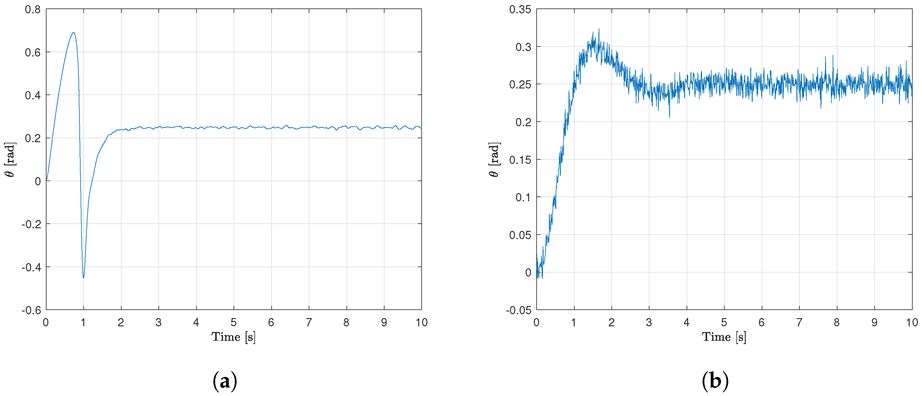
Figure 4 shows the convergence of the orientation angle toward the value required to stabilize the platform and maintain a constant force in the environment. Angle is eventually stabilized at around 2 s in Figure 4a; the and gains determine the desired convergence rate to the equilibrium point. Meanwhile, in Figure 4b, this angle is stabilized around 4 s.
Finally, the convergence of control input is shown in Figure 5. In Figure 5a, the proposed control algorithm manages to stabilize the platform in one second, which is relatively fast. However, the speed of the response involves a lot of energy to stabilize the system, as shown by the high overshoots. On the other hand, the control input in [21] converges at around 4 s and presents a higher overshoot.
7. Discussion
A PVTOL model applying a horizontal force, modeled as a spring attached between the system and the environment, was presented in this work. A Lyapunov function was used to guarantee the nonlinear system’s exponential stability, ensuring that the closed-loop system state converges exponentially to the origin. The results of numerical simulations reveal that it is possible to maintain a constant orientation angle by exerting the horizontal force required to elongate the spring a desired distance. The proposed controller has been tested in numerical simulations and the force applied to the environment converged faster to the desired interaction force than when using the controller in [21]. In addition to, results show good performance of the control strategy based on the proposed Lyapunov function.
Author Contributions
Conceptualization, R.L., S.C. and I.G.-H.; methodology, R.L.; software, S.C.; validation, R.L. and I.G.-H.; formal analysis, R.L., S.C. and I.G.-H.; investigation, R.L. and I.G.-H.; resources, R.L.; data curation, S.C.; writing—original draft preparation, S.C.; writing—review and editing, R.L. and I.G.-H.; visualization, S.C.; supervision, R.L.; project administration, R.L.; funding acquisition, R.L. All authors have read and agreed to the published version of the manuscript.
Funding
Research funded by Conacyt (2022).
Institutional Review Board Statement
Not applicable.
Informed Consent Statement
Not applicable.
Data Availability Statement
Not applicable.
Conflicts of Interest
The funders had no role in the design of the study; in the collection, analyses, or interpretation of data; in the writing of the manuscript, or in the decision to publish the results.
Abbreviations
The following abbreviations are used in this manuscript:
| PVTOL | Planar Vertical Takeoff and Landing |
| DFAV | Ducted-Fan Aerial Vehicle |
| UAV | Unmanned Aerial Vehicle |
| CMOS | Complementary Metal-Oxide-Semiconductor |
References
- Aguilar-Ibañez, C. Stabilization of the PVTOL aircraft based on a sliding mode and a saturation function. Int. J. Robust Nonlinear Control 2017, 27, 843–859. [Google Scholar] [CrossRef]
- Hernández-Castañeda, F.; Santibáñez, V.; Jurado, F. Priority altitude PVTOL aircraft control via immersion and invariance. Int. J. Control 2020, 93, 2290–2301. [Google Scholar] [CrossRef]
- Aguilar-Ibañez, C.; Suarez-Castanon, M.S.; Meda-Campaña, J.; de Jesús Rubio, J.; Martínez-Castro, J.; Barrón-Fernández, R. Shaping Energy for the Stabilization of an Unmanned Aircfrat. In Proceedings of the 2018 15th International Conference on Electrical Engineering, Computing Science and Automatic Control (CCE), Mexico City, Mexico, 5–7 September 2018; pp. 1–5. [Google Scholar]
- Aguilar-Ibañez, C.; Suarez-Castanon, M.S.; Meda-Campaña, J.; Gutierrez-Frias, O.; Merlo-Zapata, C.; Martinez-Castro, J.A. A simple approach to regulate a pvtol system using matching conditions. J. Intell. Robot. Syst. 2020, 98, 511–524. [Google Scholar] [CrossRef]
- Cariño Escobar, J.; Lozano, R.; Bonilla Estrada, M. Two PVTOLs cooperative slung-load transport control based on passivity. Adv. Control Appl. Eng. Ind. Syst. 2020, 2, e22. [Google Scholar] [CrossRef]
- Aguilar-Ibañez, C.; Sira-Ramirez, H.; Suarez-Castanon, M.S.; Garrido, R. Robust trajectory-tracking control of a PVTOL under crosswind. Asian J. Control 2019, 21, 1293–1306. [Google Scholar] [CrossRef]
- Yao, Q. Robust constrained trajectory tracking control for a PVTOL aircraft subject to external disturbances. Int. J. Syst. Sci. 2021, 52, 2617–2629. [Google Scholar] [CrossRef]
- Kobayashi, T.; Ueda, A.; Imae, J.; Zhai, G. Obstacle avoidance control for PVTOLs based on a virtual space approach. In Proceedings of the 2009 International Conference on Networking, Sensing and Control, Okayama, Japan, 26–29 March 2009; pp. 868–872. [Google Scholar]
- Gentili, L.; Naldi, R.; Marconi, L. Modeling and control of VTOL UAVs interacting with the environment. In Proceedings of the 2008 47th IEEE Conference on Decision and Control, Cancun, Mexico, 9–11 December 2008; pp. 1231–1236. [Google Scholar]
- Marconi, L.; Naldi, R. Control of aerial robots: Hybrid force and position feedback for a ducted fan. IEEE Control Syst. Mag. 2012, 32, 43–65. [Google Scholar]
- Forte, F.; Naldi, R.; Macchelli, A.; Marconi, L. Impedance control of an aerial manipulator. In Proceedings of the 2012 American Control Conference (ACC), Montreal, QC, Canada, 27–29 June 2012; pp. 3839–3844. [Google Scholar]
- Forte, F.; Naldi, R.; Macchelli, A.; Marconi, L. On the control of an aerial manipulator interacting with the environment. In Proceedings of the 2014 IEEE International Conference on Robotics and Automation (ICRA), Hong Kong, China, 31 May–7 June 2014; pp. 4487–4492. [Google Scholar]
- Huerzeler, C.; Naldi, R.; Lippiello, V.; Carloni, R.; Nikolic, J.; Alexis, K.; Siegwart, R. Airobots: Innovative aerial service robots for remote inspection by contact. In Proceedings of the 2013 IEEE/RSJ International Conference on Intelligent Robots and Systems, Tokyo, Japan, 3–8 November 2013; p. 2080. [Google Scholar]
- Albers, A.; Trautmann, S.; Howard, T.; Nguyen, T.A.; Frietsch, M.; Sauter, C. Semi-autonomous flying robot for physical interaction with environment. In Proceedings of the 2010 IEEE Conference on Robotics, Automation and Mechatronics, Singapore, 28–30 June 2010; pp. 441–446. [Google Scholar]
- Fumagalli, M.; Naldi, R.; Macchelli, A.; Carloni, R.; Stramigioli, S.; Marconi, L. Modeling and control of a flying robot for contact inspection. In Proceedings of the 2012 IEEE/RSJ International Conference on Intelligent Robots and Systems, Algarve, Portugal, 7–12 October 2012; pp. 3532–3537. [Google Scholar]
- Jung, S. A position-based force control approach to a quad-rotor system. In Proceedings of the 2012 9th International Conference on Ubiquitous Robots and Ambient Intelligence (URAI), Daejeon, Korea, 26–28 November 2012; pp. 373–377. [Google Scholar]
- Jeong, S.H.; Jung, S. Bilateral teleoperation control of a quadrotor system with a haptic device: Experimental studies. In Proceedings of the 2014 IEEE International Conference on Robotics and Automation (ICRA), Hong Kong, China, 31 May–7 June 2014; pp. 543–548. [Google Scholar]
- Nguyen, T.W.; Hosseinzadeh, M.; Garone, E. Thrust vector control of constrained multibody systems. Automatica 2021, 129, 109586. [Google Scholar] [CrossRef]
- Shi, F.; Zhao, M.; Anzai, T.; Ito, K.; Chen, X.; Nozawa, S.; Inaba, M. Multi-rigid-body dynamics and online model predictive control for transformable multi-links aerial robot. Adv. Robot. 2019, 33, 971–984. [Google Scholar] [CrossRef]
- Gruszka, A.; Malisoff, M.; Mazenc, F. On tracking for the PVTOL model with bounded feedbacks. In Proceedings of the 2011 American Control Conference, San Francisco, CA, USA, 29 June–1 July 2011; pp. 1428–1433. [Google Scholar]
- Wopereis, H.W.; Hoekstra, J.J.; Post, T.H.; Folkertsma, G.A.; Stramigioli, S.; Fumagalli, M. Application of substantial and sustained force to vertical surfaces using a quadrotor. In Proceedings of the 2017 IEEE International Conference on Robotics and Automation (ICRA), Singapore, 29 May–3 June 2017; pp. 2704–2709. [Google Scholar]
Figure 1.
PVTOL configuration. The red component represents the actual force applied by the PVTOL, acting in the opposite direction of the desired force with which the spring resists elongation.
Figure 1.
PVTOL configuration. The red component represents the actual force applied by the PVTOL, acting in the opposite direction of the desired force with which the spring resists elongation.

Figure 2.
Behavior of the x displacement. (a) Using the proposed controller. (b) Using the controller in [21].
Figure 2.
Behavior of the x displacement. (a) Using the proposed controller. (b) Using the controller in [21].

Figure 3.
Behavior of the force. (a) Using the proposed controller. (b) Using the controller in [21].
Figure 3.
Behavior of the force. (a) Using the proposed controller. (b) Using the controller in [21].

Figure 4.
Behavior of the angle. (a) Using the proposed controller. (b) Using the controller in [21].
Figure 4.
Behavior of the angle. (a) Using the proposed controller. (b) Using the controller in [21].

Figure 5.
Behavior of the control input. (a) Using the proposed controller. (b) Using the controller in [21].
Figure 5.
Behavior of the control input. (a) Using the proposed controller. (b) Using the controller in [21].


Table 1.
Initial conditions and simulation constants.
| Initial Condition | Value | Constant | Value | Gain | Value |
|---|---|---|---|---|---|
| 0 (m) | 5 (N/m) | 20 | |||
| 0 (m/s) | 5 (N) | 5 | |||
| 0 (rad) | m | 2 (kg) | 30 | ||
| 0 (rad/s) | g | 9.81 (m/s2) | 30 |
Publisher’s Note: MDPI stays neutral with regard to jurisdictional claims in published maps and institutional affiliations. |
© 2022 by the authors. Licensee MDPI, Basel, Switzerland. This article is an open access article distributed under the terms and conditions of the Creative Commons Attribution (CC BY) license (https://creativecommons.org/licenses/by/4.0/).
Share and Cite
MDPI and ACS Style
Lozano, R.; Calderón, S.; González-Hernández, I. Lyapunov Stability of a Planar Vertical Take-Off and Landing Aircraft Exerting a Force in the Environment. Drones 2022, 6, 144. https://0-doi-org.brum.beds.ac.uk/10.3390/drones6060144
AMA Style
Lozano R, Calderón S, González-Hernández I. Lyapunov Stability of a Planar Vertical Take-Off and Landing Aircraft Exerting a Force in the Environment. Drones. 2022; 6(6):144. https://0-doi-org.brum.beds.ac.uk/10.3390/drones6060144
Chicago/Turabian StyleLozano, Rogelio, Samantha Calderón, and Iván González-Hernández. 2022. "Lyapunov Stability of a Planar Vertical Take-Off and Landing Aircraft Exerting a Force in the Environment" Drones 6, no. 6: 144. https://0-doi-org.brum.beds.ac.uk/10.3390/drones6060144