

Research on Service Function Chain Embedding and Migration Algorithm for UAV IoT


School of Electronic and Information Engineering, Harbin Institute of Technology, Harbin 150001, China
*
Author to whom correspondence should be addressed.
Drones 2024, 8(4), 117; https://0-doi-org.brum.beds.ac.uk/10.3390/drones8040117
Submission received: 14 February 2024
/
Revised: 19 March 2024
/
Accepted: 21 March 2024
/
Published: 22 March 2024
(This article belongs to the Special Issue Advances of Drones in Green Internet-of-Things)
Abstract
:This paper addresses the challenge of managing service function chaining (SFC) in an unmanned aerial vehicle (UAV) IoT, a dynamic network that integrates UAVs and IoT devices for various scenarios. To enhance the service quality and user experience of the UAV IoT, network functions must be flexibly configured and adjusted based on varying service demands and network situations. This paper presents a model for calculating benefits and an agile algorithm for embedding and migrating SFC based on particle swarm optimization (PSO). The model takes into account multiple factors such as SFC quality, resource utilization, and migration cost. It aims to maximize the SFC benefit and minimize the migration times. The algorithm leverages PSO’s global search and fast convergence to identify the optimal or near-optimal SFC placement and update it when the network state changes. Simulation experiments demonstrate that the proposed method improves network resource efficiency and outperforms existing methods. This paper presents a new idea and method for managing SFC in UAV IoT.
1. Introduction
1.1. Background and Research Motivation
With the rapid development of wireless communication technology, unmanned aerial vehicles (UAVs), as flexible, efficient, and low-cost air platforms, have become widely utilized in civil, military, commercial, and other fields [1]. UAVs can be equipped with a variety of IoT devices, such as sensors, cameras, and GPS modules, forming an airborne IoT system that provides a range of services to users on the ground, including monitoring, communication, and sensing [2]. However, the dynamic, heterogeneous, and distributed nature of UAV networks brings significant challenges for network management and optimization. In order to enhance the service quality and user experience of UAV networks, it is essential to flexibly configure and adjust the network functions to meet various business requirements and network conditions [3].
Network virtualization is a technology that implements multiple virtual networks on the same physical network to improve the utilization, flexibility, and innovation of network resources [4]. Network virtualization enables the software and programmability of network functions, reduces network costs and complexity, and improves the delivery speed and quality of network services. By employing network virtualization technology, network functions can be virtualized into VNFs (virtualized network functions), which can be deployed at various layers of the UAV network to achieve quick configuration, adjustment, and migration of network functions. This enhances the performance, reliability, and security of the UAV network [5].
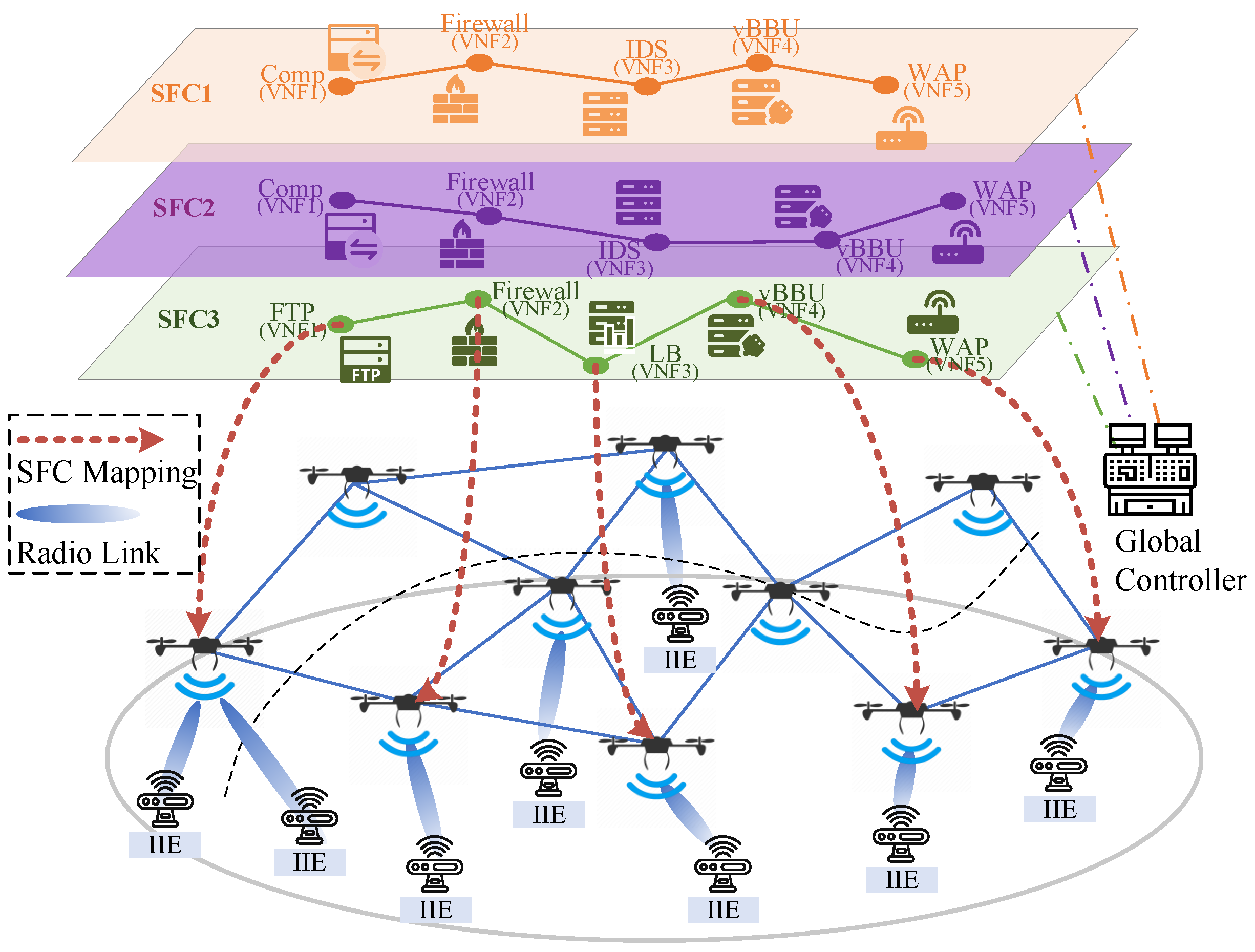
Based on VNFs and software-defined networking (SDN) technologies, service function chaining (SFC) connects network functions in a specific sequence to achieve flexible orchestration and scheduling of network functions, adapting to different service scenarios and network states, as shown in Figure 1. Because of its network characteristics, which combine UAVs and IoT devices, it can support a variety of complex business scenarios, such as emergency rescue, intelligent transportation, and smart agriculture [5]. These service scenarios have diverse network requirements, such as high bandwidth, low latency, and high reliability. In order to meet these requirements, network functions need to be carefully controlled and optimized to achieve on-demand combination and customization of network functions [6]. Therefore, the SFC has significant application value and research significance in UAV IoT.
1.2. Network Architecture and Challenges
The network architecture we used for the UAV IoT leverages SFC based on VNF and SDN technologies, as shown in Figure 1. This design enables a dynamic and flexible orchestration of network functions to cater to varying service scenarios and network states.
System Overview: A fundamental component of the architecture is a set of UAVs, each equipped with a common computing platform capable of hosting multiple virtual machines (VMS). These virtual machines provide a deployment environment for SFC services requested by terrestrial Industrial IoT equipment (IIE) to support the transmission of service data.
Network Resources: We consider the four most typical node resources provided by the UAV, namely, the computing resources (CPU), represented by the number of CPU cores; the memory resources (RAM), represented by the size of the cache space; the storage resources (DISK), represented by the size of the disk space; and the energy consumption resources (ENG), represented by the battery capacity on the UAV. Without loss of generality, we consider the most typical transmission bandwidth (BAND), that is, the maximum rate of data transmission between two UAVs.
Global Controller: Within the network’s deployment domain, the global controller acts as a command and communications hub, coordinating the entire UAV network. It is responsible for policy implementation of SFC embedding and migration across UAVs. The controller can be deployed for ground stations or spaceborne platforms.
SFC Embedding Workflow: When the IIE sends an SFC setup request to the UAV network, the workflow starts. After receiving the request, the UAV relays the request to the VNF manager located in the global controller. According to the resource quantity and quality of service (QoS) requirements in the request, the VNF manager uses the embedded algorithm to divide node and link resources on the computing platform of each UAV and establish SFC in the UAV network. Then, SDN technology is used to configure network routing and manage the forwarding of service data.
Real-Time Monitoring and Adaptation: The global controller continuously monitors the performance of SFC on the network in real time. The SFC migration algorithm is triggered when the network topology changes and the link fails or the QoS fails to meet the SFC requirements. This process includes invalidating the existing VNFs, removing the existing VNFs, establishing a new VNFS, and then rerouting to complete the establishment of the new SFC.
The architecture is designed to provide a robust, adaptable, and efficient communication network for UAV IoT systems, capable of supporting complex IIE data transfers with high reliability and flexibility. The research in this paper is based on two observations in this network architecture:
- (1)
- SFC has life cycle characteristics and requires maintenance during operation. Its life cycle includes creation, embedding, operation, migration, and destruction. Due to the dynamic characteristics of the network, such as UAV movement, network topology changes, and resource fluctuations, system performance may deteriorate or services may even be interrupted. Therefore, real-time monitoring and maintenance of the SFC are essential to guarantee the availability and reliability of the SFC.
- (2)
- Due to the particularity of UAV energy consumption, load balancing should be considered in the embedding algorithm. If the SFC embedding algorithm does not consider the energy consumption resources of UAVs, it may lead to the premature depletion of UAVs’ energy or an imbalance of energy consumption among UAVs, thus affecting the stability and sustainability of UAVs’ dynamic network.
Based on the above observations, the challenge of this research is to design an SFC embedding algorithm deployed on a global controller. The algorithm can dynamically select the appropriate UAV as the SFC execution node according to the energy consumption resources and network status of the UAV, so as to achieve efficient SFC embedding and balance the energy consumption of the UAV. At the same time, in order to ensure the service continuity during the SFC life cycle, the algorithm can dynamically migrate SFC according to the real-time performance of SFC and the energy distribution of the UAVs.
1.3. Contributions
The main contributions of this paper are as follows:
- Aiming to address the resource perception problem of SFC in UAV dynamic networks, a revenue calculation model based on SFC operation process monitoring is proposed. This model comprehensively considers the service quality, resource utilization, and migration cost of SFC.
- An agile algorithm for embedding and migrating SFC based on particle swarm optimization (PSO) is proposed. It can quickly find the optimal or nearly optimal embedding scheme to meet the requirements of SFC and facilitate the agile migration of SFC when the network state changes.
- A simulator and simulation environment based on MANO architecture has been developed. It is capable of simulating dynamic network topology, SFC operation processes, embedding, and migration processes.
- The experimental results demonstrate that the proposed method outperforms the comparison algorithm in terms of SFC income, migration quality, and resource utilization, thus confirming the effectiveness and superiority of the proposed method.
2. Related Work
In this paper, from the perspective of network operators, we focus on the SFC embedding and migration problem of UAV dynamic network topology under the scenario of a large number of SFC service requests. This section will introduce some representative and high-quality related studies from recent years.
2.1. SFC Embedding
The software implementation of VNFs provides the flexibility for service providers to deploy SFC in the existing networks. Therefore, a critical issue to be solved is how to determine the deployment location of each VNF in the SFC, which is called the SFC embedding problem.
Beck et al. [7] took the lead in bringing this problem to researchers’ attention and proposed a universal virtual network framework that embedded multiple virtual networks onto the base network. On this basis, a heuristic algorithm is used to coordinate the embedding of VNF chains with the goal of minimizing bandwidth utilization [8]. However, the framework is oriented to the large-capacity server of the computing center and cannot be directly applied to the UAV computing platform. With the goal of minimizing the total deployment cost, Tomassilli et al. [9] designed an optimal algorithm based on tree topology to optimally place VNFs when meeting all SFC requirements of the stream. Sallam et al. [10] expressed the maximum flow problem constrained by SFC as the fractional multi-commodity flow problem and then solved it. Jin et al. [11] expressed the VNF chain deployment problem as mixed-integer linear programming (MILP) to minimize total resource consumption in the context of computing service deployment on the edge service area. However, due to their dependence on prior knowledge and high computational complexity, these offline methods are difficult to apply to online placement scenarios.
In recent years, some researchers have turned their attention to hybrid SFC embedding problems, such as bidirectional SFC based on real-world business needs. Zheng et al. [12] define a new problem for minimum delay hybrid SFC embedding (ML-HSFCE) and propose an optimal hybrid SFC embedding algorithm (Opt-HSFCE). They extended this work in [13], proposing the first 2-approximation algorithm to jointly optimize the processes of h-SFC construction and embedding, which is called Eulerian-circuit-based hybrid SFP optimization (EC-HSFP). Dimolitsas et al. [14] proposed a distributed VNF embedding method (DVNE) to embed two SFC round-trips with the goal of minimizing round-trip latency. The problem of hybrid SFC embedding focuses on the service delay after the completion of embedding, and the service delay in these studies is mainly described by the hop number in the middle of the node, which does not accord with the fact that a large amount of delay also exists in the virtual resource scheduling on each computing platform.
2.2. SFC Migration
The embedding of SFC in ground infrastructure has been widely studied, but the research progress on the embedding of SFC in a platform with high mobility, such as a UAV network, is relatively slow. Although Vidal et al. [15] has built a UAV network test platform supporting SFC to verify its effectiveness, its highly dynamic and changing topology poses challenges to the real-time migration effect of SFC services.
Carpio et al. [16] investigated the problem of optimal placement of hybrid SFC from an Internet service provider (ISP) perspective and proposed a two-stage optimization process to analyze the performance impact of replication and migration of VNF. They extended the work using a traffic forecasting approach [17] to reduce migration costs. Rui et al. [18] modeled the SFC as a Petri net model and obtained reliability evaluation results related to execution time. Then, a VNF migration strategy with reliability as the optimization objective and cost as a consideration was designed. While the above study noted the importance of SFC migration on cloud computing platforms, it focused more on migrating SFC to accommodate the dynamic changes in services traffic, which is different from the dynamic nature of deploying SFC on UAV networks.
Qin et al. [3] described the application scenario of SFC for vehicle-assisted or UAV-assisted edge computing, studied the SFC migration problem in dynamic networks with long-term cost budget constraints, and used the Lyapunov optimization method to solve it. In the same scenario, Bai et al. [19] used a quantitative modeling method based on semi-Markov process to study the potential impact of VNF migration time and network elasticity in SFC. In order to maximize the acceptance rate of service function chain requests (SFCRs) and reduce VNF migration and energy consumption as much as possible, Hu et al. [20] summarized the relevant factors such as node status, link status, energy consumption, migration node, and mapping success. Then, the VNF migration algorithm was designed using the actor-critic model, graph convolutional network, and LSTM network.
The optimization goal of these studies is to maximize the success rate of SFC embedding and improve the system benefits. However, considering that there is a life cycle of SFC, the revenue calculation of SFC cannot be determined only by whether it completes the embedding, and the supervision in its operation process is equally important, which is missing in the above research.
3. System Model
In this section, we describe the system model in five aspects, including the substrate network, the service function chain, the SFC embedding, the SFC latency, and the SFC revenue. Then, we formulate the problem as an integer programming model. The symbols used in this paper are summarized in Table 1.
3.1. Substrate Network Model
The base network is represented as an infrastructure by an undirected graph , with network nodes denoted as , and for each physical node. Due to topological dynamics, we define as an adjacency matrix, unlike the typical definition of links in graphs, and each element in the matrix is determined by a function of time t. Thus, there is a set of physical links , and for each physical link , represents the link between node and node , where:
The physical node serves as a server to provide resources for the deployment of SFC, utilizing the function to describe the maximum resource capacity, and the function to describe the remaining resources at time t. In this paper, we consider four types of physical node resources: CPU, RAM, DISK, and ENG. Therefore, for node , its resource capacity is , and the remaining resource at time t is . Different from other researchers’ definitions of network node resources, this paper includes energy consumption resources. It considers UAVs as deployment platforms for physical nodes, with their batteries providing limited power. This is distinct from CPU, RAM, DISK, and other occupation-release resources, as energy consumption is one-time. The resource for a physical link is the transmission bandwidth (BAND). For link , its maximum resource capacity is . As with node resources, SFC in the network will continue to occupy part of the transmission bandwidth between UAVs, so we need to pay attention to the remaining situation of link resources in real time, so as to facilitate the embedding of the new SFC and realize the full utilization of link resources. The remaining resource at time t is . The deployment of VNF on physical nodes requires latency for creation and task queues.
We refer to the “Wait-Time Matrix” proposed by Boutin et al. [21] to describe the time that must be waited to request resources from the computing platform on the UAV. We consider that the DISK resources of a node are determined by the total size of the embedded functional software, which is pre-installed on the platform, while the different SFC only activates the software on demand, and the activation time is very short. What really affects the VNF operation time is the number of CPU cores applied for the SFC and the cache of service data. Therefore, the time waiting matrix is determined by the index of CPU resources and RAM resources, a consideration consistent with Boutin et al. [21] ’s cluster design for the Microsoft cloud computing platform. The difference is that the table is designed as the index of the remaining resources of the node. For the sake of generality, we set the index granularity to 1 resource unit. The more remaining resources, the shorter the waiting time, and the tighter the remaining resources, the longer the scheduling time of the resources required to complete the task. We define a latency matrix for servers in each physical node as . The matrix is indexed by the current CPU resources and the remaining amount of RAM resources of the node, that is, . The value indexed in the table represents the latency required for VNF preparation on the server when requesting resources.
3.2. Service Function Chain Model
We define the set of SFCs to be processed as . For an SFC , we utilize the directed graph to represent the virtual network structure of the service function chain. In this structure, the VNF virtual node is denoted as , and for each virtual node, there exists . To align with the physical links in the base network, virtual links are defined using the adjacency matrix . In other words, , where each virtual link , denotes the link between virtual node and virtual node . Of which:
The advantage of using an adjacency matrix to define a network function chain is that it provides convenience for extending subsequent service functions. Schneider et al. [22] has proposed that the virtual network embedding with complex functions may not always exhibit a perfect chain structure. In some cases, bidirectional networks containing loops may be necessary to support complex applications, such as optimizing network video transmission and inserting advertisements, thereby achieving the network slicing effect.
SFC construction involves requesting resources from the base network to sequentially build VNF virtual nodes and connect them through virtual links. We use the function to describe the amount of resources that SFC applies to the base network. The resources utilized are the four types available in the substrate network. For a virtual node , the allocated resources are denoted as and . The purpose of the virtual link is to request transmission bandwidth from the base link. Therefore, for the virtual link , the requested resource occupation applied for is . Li et al. [23] point out that the SFC for achieving complete wireless access functionality for the industrial Internet of things should include a wireless access node and industrial Internet of things equipment , as shown in Figure 1. In this paper, we assume that all UAV nodes have wireless access functions to enable random access of Internet of things equipment. The functions and configurations of these two nodes do not vary across different SFCs, which is not the focus of this paper. Therefore, they will not be discussed further.
When a user requests resources from the network, the network controller must specify the duration for which the resources will be occupied. This allows the network controller to determine when to release the occupied resources and reallocate them to other users, thereby improving the efficiency of network resource utilization. In order to implement this function, the arrival time of SFC is defined as , and the service duration, which is the life cycle of SFC, is defined as . Therefore, the end time of service can be calculated as . This paper focuses on the transmission latency in the quality of service (QoS) requirements that users submit to the network. It should be noted that in SFC resource allocation, the energy consumption resource of virtual node is interrelated with other resources, and its magnitude should not be specified from the user’s perspective. Su et al. [24] highlight that in the actual operation of VNFs, CPU energy consumption accounts for a larger share compared to RAM and DISK. We used Su et al.’s assumption [24] (i.e., the mapping relationship between energy consumption resources, CPU, and running time in the resources applied by virtual node is ). When SFC arrives at , the controller anticipates the future energy consumption of the virtual node based on this, and then selects the appropriate deployment location.
3.3. SFC Embedding Model
For SFC , at time t, the mapping indication of a virtual node to a physical node is defined as , where represents the mapping of virtual node to physical node . The mapping indication that defines the virtual link to the physical link is represented as , where represents the mapping of virtual link to physical link .
Since the resources provided by physical nodes are limited, the total resources occupied by VNFs running on them must not exceed the upper limit of available resources. Therefore, the mapping of virtual nodes needs to satisfy the following constraint relations:
Similarly, because the transmission bandwidth of the physical links between UAVs is limited, the requested bandwidth of the virtual link of SFCf mapped to a physical link cannot be greater than the remaining bandwidth. Therefore, the mapping of virtual links must meet the following constraint:
We do not consider the scenario where a VNF virtual node in SFCf can be deployed and operated concurrently on multiple physical facilities, that is, the virtual node cannot be mapped to multiple physical nodes. Therefore, there is the following constraint:
Considering the dynamic nature of network topology, the prerequisite for successful virtual link mapping is the existence of physical links in the base network. Therefore, there is the following constraint:
At the same time, we refer to wang et al. [25], using a flow model approach to ensure that the virtual links mapped from SFC f to the base network traverse the VNF virtual nodes in a specified order. We represent the set of incoming and outgoing links of physical node as and , respectively. Additionally, and represent the destination and source VNF of virtual link , respectively. According to the flow model, all the outgoing traffic from nodes should be equal to the incoming traffic, and this constraint exists only for the virtual nodes and links to which SFC is mapped. Therefore, the constraint can be expressed as:
3.4. SFC Latency Model
3.4.1. Operation Latency
We analyzed the transmission delay of an SFC and discovered that the propagation delay and transmission delay are significantly influenced by the size of the data packet. This size is closely related to the SFC’s service type and is also affected by the client and server’s sending and receiving mechanisms, which are designed by the user and not taken into account by the operator. As an infrastructure leasing service, the primary concern should be the scheduling latency of running VNFs on each physical node. We provided the model for server latency in physical nodes with the “Wait-Time Matrix” at the end of Section 3.1. Considering that multiple VNFs in the SFC are running in parallel to process the service data flow at time t, the delay bottleneck may occur in one of the VNFs. This can be expressed as:
Mapping can only be completed if the SFC’s runtime latency meets its QoS requirements. Therefore, there are the following constraints:
3.4.2. Remap Latency
When a virtual node mapping needs to be migrated from one physical node to another, the delay primarily arises from requesting resources from the server and retransmitting cached data. We use the indicator vector to determine the migration relation of the mapping of virtual node at time t. The calculation method is , where represents the vector composed of the mapping relation of virtual node and all physical nodes at time t, and the symbol ⊕ represents the exclusive OR operation between two vectors. The resulting migration delay can be calculated as follows:
where represents the 0-norm of , which is the count of non-zero elements in the vector, and determines the number of physical nodes involved in the migration process. represents the amount of buffered data that needs to be retransmitted to recover the state of virtual node , and represents the bandwidth requested by virtual link with virtual node as the destination.
3.4.3. Reroute Latency
We believe that embedding SFC into the virtual network relies on the OpenFlow table delivery mechanism of SDN to establish virtual links. Therefore, it is necessary to sequentially modify the routing tables of physical nodes to facilitate the forwarding of service traffic in SFC. The process of distributing the flow table contributes to the rerouting delay. We utilize the indicator vector to determine the migration relation of the mapping of the virtual link at time t. The calculation method is , where represents the vector composed of the mapping relation of the virtual link and all physical links at time t, and the symbol ⊕ represents the exclusive OR operation between the two vectors. The resulting migration delay can be calculated as follows:
The expression represents the 0-norm of , which is the count of non-zero elements in the vector. It is used to calculate the number of physical links involved in the migration process. represents the latency of modifying the routing table needed to modify a mapped physical link.
In summary, the total delay required for SFC service transmission is:
3.5. SFC Revenue Model
In contrast to other research studies, this paper utilizes the revenue per unit time method. This method is based on observing the dynamic service mode of SFC. SFC adjusts the mapping scheme in real time based on the network topology during operation, leading to temporary network fluctuations and a potential inability to maintain the service according to the original QoS requirements. Therefore, it is not appropriate to base revenue solely on the success of the embedding. In this paper, we employ a lenient decision method to calculate the revenue during the migration process. This means that there may be QoS nonconformity during the migration process, but it is essential to ensure that the QoS requirements can be satisfied after migration. By setting the QoS violation device gain to 0, we can suppress the behavior of frequently performing migration that affects SFC traffic transmission. The unit revenue earned at a given time can be calculated as follows:
where represents the resource price per node, and represents the resource price per link. is an indicator variable used to indicate whether the SFC violates QoS requirements at time t, that is:
Let us discuss this expression in the context of different situations:
Case 1: When migration does not occur at time t, the migration indicator variables and are both zero vectors, and the total delay is solely the waiting delay of the migrated SFC in the regular operation of the base network. Since the SFC has been embedded, the delay must satisfy the constraint condition that is less than the QoS requirement (i.e., ), so the revenue is calculated normally.
Case 2: When migration occurs at time t, the migration indicator variables and are not zero vectors. The total delay at this time includes the remapping delay, the waiting delay of the SFC operation, and the rerouting delay in the migration process. It is necessary to determine whether the delay is less than the QoS delay requirement . The result is if the requirement is met, and the payoff is calculated normally; it is if the requirement is not met, in which case the payoff is 0.
As a result, the unified expression for income calculation before and after SFC migration is achieved. When SFC completes its service life cycle, revenue settlement occurs:
It should be noted that this definition also differs from the definition of SFC revenue in other studies. We calculate the revenue of SFC throughout its entire life cycle, rather than just completing the embedding process. If the SFC fails to map after migration due to an operation taking place during migration (i.e., if the SFC ends abnormally), it will be recorded as 0 along with the revenue before migration. This is designed from the perspective that incomplete traffic transmissions will be meaningless. We also hope that the designed algorithm will be integrated into SFC and that the integrity of its traffic will be guaranteed, rather than executing multiple broken traffic transmissions to generate revenue.
During the continuous operation of the network, we prioritize the long-term average revenue of operators:
3.6. Problem Formulation
The aim of this paper is to maximize the long-term average return for operators. Problem 1 can be expressed as follows:
It should be noted that this is a non-traditional integer programming problem with a time-dependent objective function that needs to be solved quickly, requiring the algorithm to perform well online. At the same time, the decision variables in this problem are discrete 0 and 1 variables related to time, and the constraint conditions are complex and change over time, making this problem strongly discrete and dynamic.
3.7. Hardness Analysis
The challenge of solving problem 1 mainly arises from its extensive solution space. This can be analyzed as follows: the solution space size of node mapping is , and the solution space of link mapping is . From the perspective of the online algorithm, only one SFC embedding at a time is considered, simplifying the problem to the knapsack problem with a solution space of . However, the complexity of the problem is further increased by introducing the interaction between time and multiple knapsacks. Rost et al. [26] has proposed that the problem of virtual network embeddings is abstracted as a graph mapping problem and specified using the 3SAT model. The NP-completeness of SFC mapping in a static topology has been proven. Considering the complex constraints, such as dynamic topology and delay, the problem remains NP-hard and non-approximable.
4. Algorithmic Descriptions
4.1. Particle Swarm Optimization for SFC Embedding
Inspired by the regularity of bird flocks’ foraging behavior, James Kennedy and Russell Eberhart developed a simplified algorithm model [27], which eventually evolved into particle swarm optimization (PSO) after years of refinement. In order to fully utilize the particle swarm optimization algorithm’s ability to search for function extrema in a continuous domain, we consider the probability of mapping a virtual node to each base network node in SFC as the position variable of a particle. Therefore, the dimension of each particle is , and the position of the i-th particle is:
The range of particle positions is given by , and the velocity of the i-th particle is:
We define the mapping relationship between the particle’s position and the node when SFC is embedded as:
That is, for the virtual node , we will extract the probability vector representing the mapping from particles to physical nodes, and select the position with the highest probability to execute the embedding action.
The optimal position sought by the i-th particle in the PSO algorithm (i.e., the individual optimal solution) is:
The population searches for the optimal position, which is the global optimal solution:
The fitness value of the optimal position searched by the i-th particle (i.e., the optimization function ) is defined as:
That is to say, if embedding the i-th particle according to its position violates the constraint and results in embedding failure, the fitness value is set to the maximum value. If the embedding is successful, the fitness value is calculated based on the revenue generated by the embedding scheme. Note that we do not directly use Equation (13) as the fitness function because we believe that there is a distinction between the success of the embedding and the transient nature of the QoS violation. There may be a situation where embedding is successful, but the delay in the process of embedding SFC and migration exceeds the QoS requirement. Equation (13) directly calculates this part of the benefit as 0, but further exploration should be encouraged in the PSO algorithm. We calculate the difference between the delay caused by the current mapping and the QoS delay requirement. Then, we combine this with the benefit to incentivize particles to move towards positions in the solution space where the SFC delay is minimized. The lowest fitness value among all particles is taken as the global optimal fitness value .
The velocity update formula for the i-th particle is:
The position update formula is:
Where N represents the number of particles, K represents the number of iterations, and omega is inertia weight. Additionally, and are learning factors, while and are random numbers within a specific interval used to enhance the randomness of the search.
The complete flow of the algorithm is shown in Algorithm 1. We give the steps of the proposed algorithm in detail, and we believe that it provides an effective method to solve the problem of online SFC embedding and migration. The computational complexity of a particle swarm optimization algorithm can usually be expressed as , where D is the particle dimension, which in our problem is calculated as . Meanwhile, the Djikstra algorithm was used to perform routing and link mapping between two VNFs, whose complexity is . Therefore, the complexity of the algorithm proposed in this paper is .
| Algorithm 1 Particle Swarm Optimization Algorithm for SFC Embedding | |
| Input: Current substrate network ; Current SFC request f; Dimension of particle position ; Max iterations ; Number of particles . | |
| Output: SFC embedding scheme node mapping and link mapping , indicating whether embedding succeeds. | |
| 1: | for all each particle i do |
| 2: | for all each dimension d do |
| 3: | Randomly initialize the particle position in the range [0,1]; |
| 4: | Randomly initialize the particle velocity in the range [0,1]; |
| 5: | end for |
| 6: | end for |
| 7: | Initialize current iteration number ; |
| 8: | while |
| 9: | for all each particle i do |
| 10: | Calculate fitness value with Equation (23); |
| 11: | if the fitness is less than the particle historical optimum then |
| 12: | Set the current fitness to ; |
| 13: | end if |
| 14: | end for |
| 15: | Select the smallest historical optimal fitness value among all particles as the global optimal fitness value ; |
| 16: | for all each particle i do |
| 17: | Calculate velocity according to the Equation (24); |
| 18: | Update particle position according to the Equation (25); |
| 19: | end for |
| 20: | ; |
| 21: | end while |
| 22: | if the fitness is the limiting value then |
| 23: | ,,; |
| 24: | else |
| 25: | Convert the global optimum fitness particle position to a node embedding scheme with Equation (20); |
| 26: | Solve the shortest path between embedded nodes with Dijkstra algorithm, and the link embedding scheme is obtained; |
| 27: | |
| 28: | end if |
| 29: | return ,,; |
4.2. Analysis of Convergence of Algorithm
We conduct a dynamic analysis of the particle’s trajectory during the algorithm iteration, and the velocity update is expressed as:
Position updates are indicated by:
Let , , and .
Thus, the updates for velocity and position can be rewritten as:
The matrix form can be expressed as:
According to the hypothesis in [28], the position corresponding to the current optimal fitness value of the particle is the global optimal position, and it has become a fixed value in the long-term iteration. In this case, the dynamics model of PSO is rewritten as:
where , is the velocity vector of the particle during iteration. , and are the position vectors of particles in the iterative process. The parameters in the original formula are expressed in matrix form as follows:
We can think of this particle as a dynamic system whose coefficient matrix is:
The stability criterion of the system (i.e., ensuring that the eigenvalues of the coefficient matrix are less than 1) is used for analysis. Find the eigenvalues of the block matrix , that is, solve the equation .
For , the equation can be rewritten as:
The characteristic roots are and , respectively, under the condition .
The conditions for stable convergence are:
where . The equation can be solved as follows:
Our particle swarm optimization algorithm uses the parameters that satisfy this condition to ensure the stability of convergence. Although the parameter selection conditions that make the algorithm in this paper converge can be analyzed from the above content, an important decision of whether the particle swarm converges still depends on the fitness function with Equation (23). The fitness function determines the movement direction of the particle and affects the process of particle searching for the optimal solution, while the design of learning factors and weights ensures the asymptotic stability of the particle adjustment process. The complexity of the fitness function lies in its discreteness. Although we make the particle variables continuous by mapping probabilities, the function values are still discrete, and the direct reason for this is the discrete network structure. We have not yet solved how to prove the discreteness of the algorithm directly from the fitness function, but only hope that the embedding strategy of SFC under the learning factors and weights of PSO is not so sloppy.
5. Performance Evaluation
5.1. Simulation Model
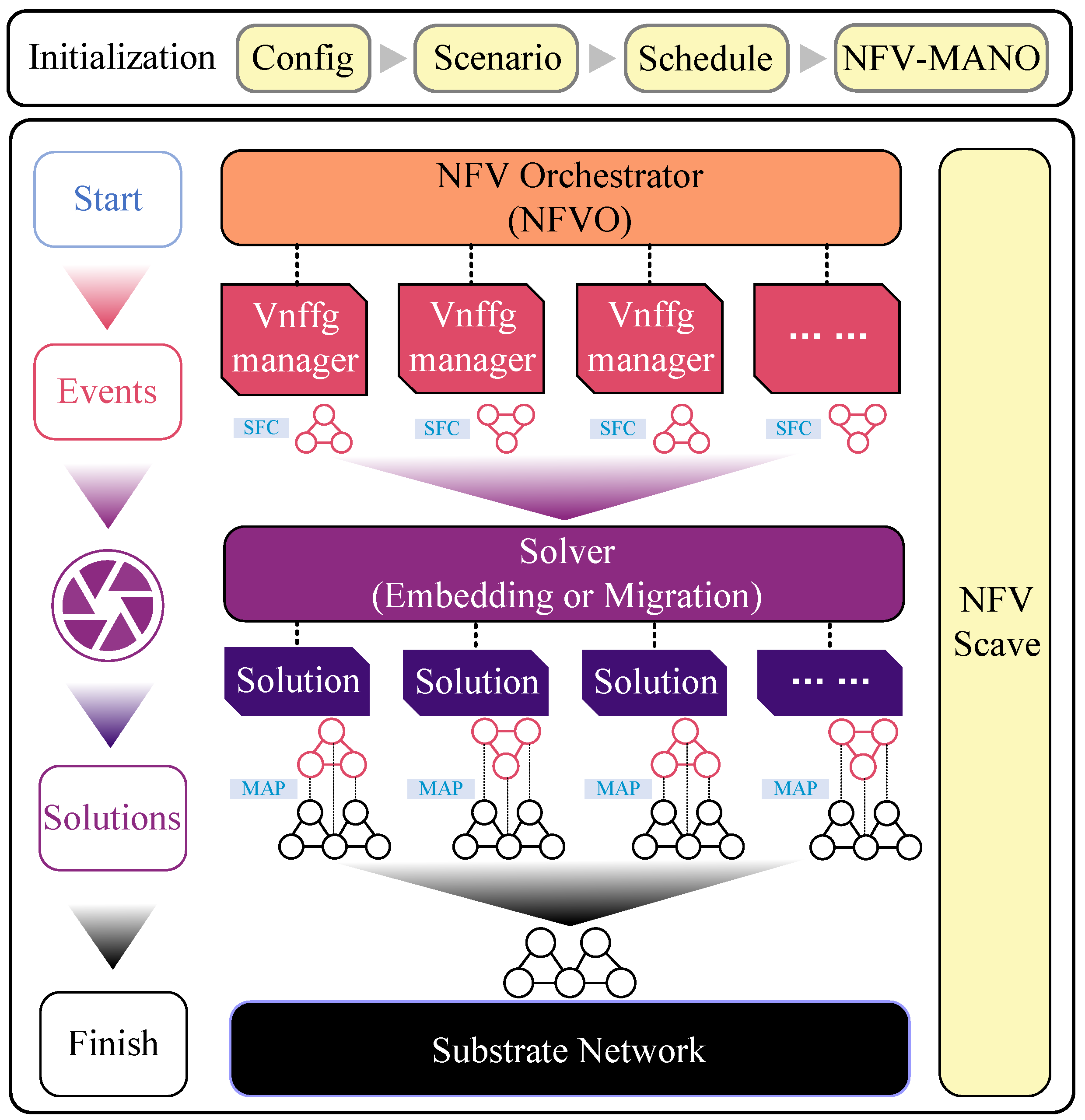
In order to validate the effectiveness and performance of the proposed resource-aware SFC embedding and migration algorithm for UAV dynamic networks, we developed a simulation framework for SFC embedding based on MANO architecture using Python 3.9 (https://gitee.com/WangXi_Chn/mini_sfc, accessed on 3 February 2024), with reference to [29], as shown in Figure 2.
Designed and proposed by the European Telecommunications Standards Institute (ETSI), the MANO architecture provides a well-defined framework for NFV that is particularly adept at handling the intricate dependencies and operational dynamics of network services. The MANO architecture’s ability to interface with various virtual network functional infrastructure (VNFI) domains makes it better suited for the heterogeneous environment of UAV IoT, where interoperability and integration with different network elements and services is critical. We designed the simulation model of SFC embedding and migration algorithm with reference to MANO architecture, so that it has certain standardization, reproducibility, and replicability.
The simulation framework mainly comprises the following components:
- The initialization model is used to configure and schedule events in simulation scenarios, initialize all NFV-MANO modules, and make preparations for the simulation.
- The virtual network function orchestrator (VNFO) model is used to orchestrate and manage the SFC. This includes tasks such as creating, embedding, migrating, and destroying the SFC, as well as calculating the revenue model of the SFC and optimizing the objective function through a solver.
- The virtual network function forwarding graph (VNFFG) model describes the topology, functional requirements, and quality of service of the SFC, as well as the life cycle status of the SFC, including creation, embedding, running, migration, and destruction.
- The NFV Scave model is used to monitor and maintain SFC, which involves collecting and analyzing SFC operating status, performance indicators, energy consumption, and resources. It also includes making judgments and executing SFC migration trigger conditions.
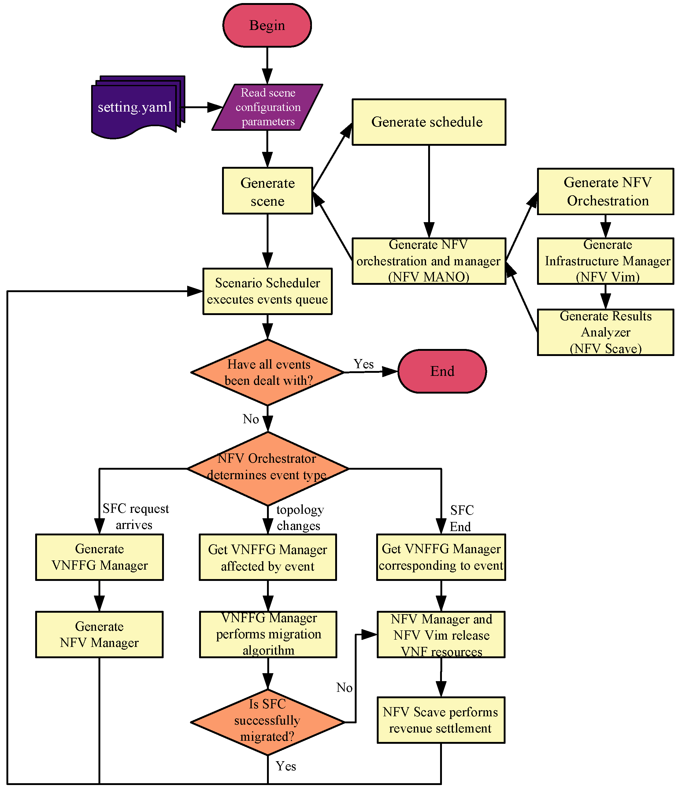
The simulation framework utilizes a discrete event-driven approach, meaning it advances the simulation clock and processes events based on their occurrence time and type. Events are primarily categorized into endogenous events and exogenous events. Endogenous events are those caused by state changes resulting from internal activities of the system, such as the creation, embedding, migration, and destruction of SFC, while exogenous events are those caused by external factors affecting the system, such as the movement, communication, and energy consumption of UAVs. The timing and nature of events are determined by the relevant probability distribution or rules, and the processing of events is carried out using the corresponding model or algorithm. The execution flow of the simulation framework is depicted in Figure 3.
5.2. Simulation Setting
In this section, we will showcase the performance of the PSO algorithm for SFC deployment in the emulator. Since there is currently no online algorithm for income calculation based on long-term operation, this paper chooses to compare it with random and greedy strategies. Random strategy refers to NFVO randomly selecting physical nodes in the current base network for VNF embedding after receiving SFC deployment requests from the environment and SFC migration due to topology changes. The greedy strategy involves selecting physical nodes with ample remaining resources to embed as much as possible, and then using the Dijkstra algorithm to sequentially route each node for embedding virtual links.
In the simulation, we consider a UAV network with 30 nodes as the base network, and the network topology is randomly generated using the Waxman model. According to the literature [25], we set the capacity of CPU, RAM, and DISK resources of each site in the network to 20 units and set the battery capacity to 200 units. The bandwidth resource on the physical link is 200 units. For each SFC, its source and destination sites are randomly selected from the network topology, and the number of VNFs ranges from 8 to 10. Each VNF instance requires a uniformly distributed random number of CPU, RAM, and DISK resources (1–10). The requested virtual link bandwidth resource is a uniformly distributed random number between 10 and 100. The life cycle of each SFC follows a uniform distribution of (5,10) time units, and the delay requirement in QoS consists of uniformly distributed random numbers in the range of [0.2, 0.3]. We generate multiple SFC requests in the scheduler of the simulated event, and the SFC requests arrive at the system in a Poisson process sequence. At the same time, in order to simulate topological dynamics while maintaining network connectivity, the physical links are randomly dismantled and rebuilt at intervals. When the SFC’s life cycle ends, NFVO removes it from the base network to indicate that its task has been completed. Set the time cost for updating a forwarding rule on the switch when the VNF is remapped between two nodes to 0.01 unit. The minimum wait time in the delay list for applying for resources on a node is 0.01 unit. Each experiment was repeated 10 times, and the results were averaged to minimize the impact of chance.
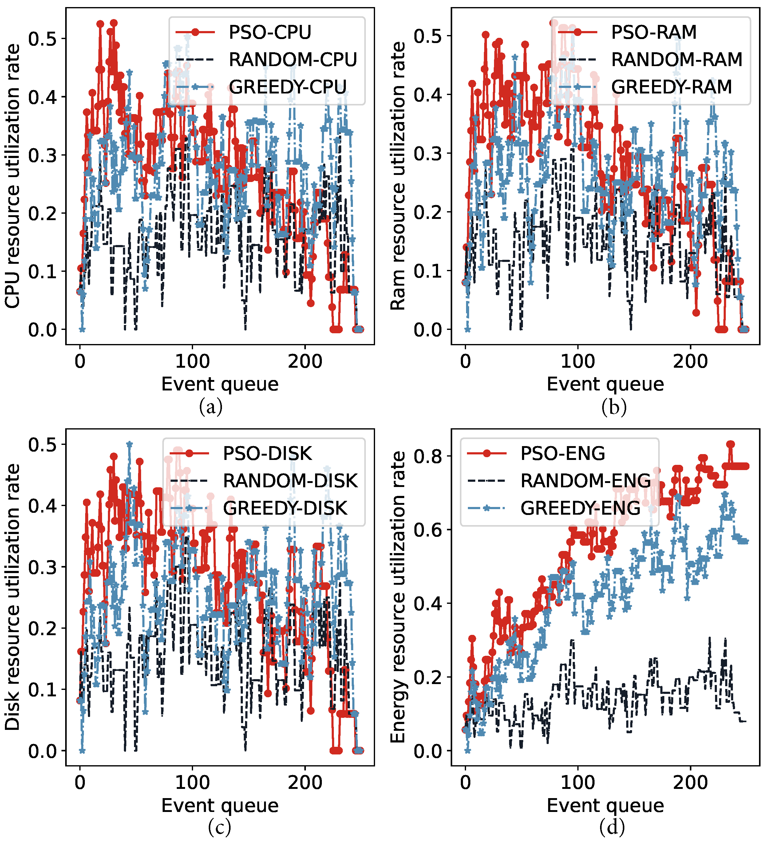
5.3. Network Resource Consumption
To evaluate the network resource awareness of the PSO, we compared it to the baseline algorithm using the simulation settings mentioned above. Figure 4 illustrates the fluctuations in the remaining CPU, RAM, DISK, and ENG resources during operation in the same network scenario. We can observe from the utilization of CPU, RAM, and DISK leased resources represented by Figure 4a–c that the PSO algorithm can effectively utilize the available resources in the network. During the initial phase of scenario operation, the SFC completion rate is high, leading to a rapid increase in resource utilization, exceeding 50%. In contrast, the baseline algorithm remains below this level for an extended period. In the later stages of the scenario operation, resource utilization under the PSO algorithm gradually decreases. This is mainly influenced by the remaining power resources on the UAV node, as depicted in the ENG consumption resource utilization represented by Figure 4d. After analyzing all the events, the utilization of network power resources under the PSO algorithm reaches 79%, while the greedy algorithm and random algorithm in the baseline algorithm correspond to 58% and 10%, respectively. It is evident that deploying SFC through the PSO algorithm can improve network resource awareness and achieve optimal resource utilization.
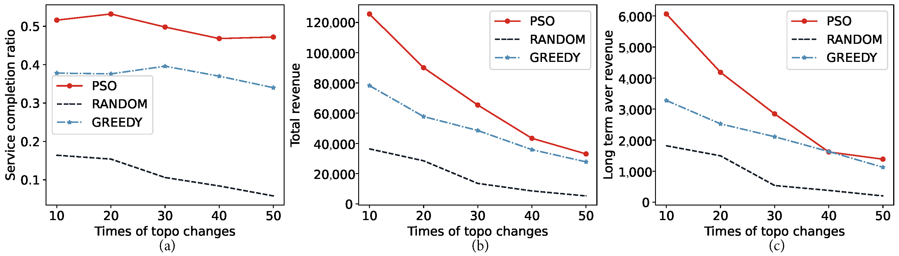
5.4. Impact of Topological Change
To assess the algorithm’s performance in a UAV network with dynamic topological changes, we introduced various topological change events at different times in the base network during the operation process. We then compared and observed the completion rate of SFC, total revenue, and long-term average revenue during the experiment. The result is depicted in Figure 5. Given that the number of network topology changes during operation falls within the range of 10 to 50, the experiment is repeated 5 times. In Figure 5a, it can be seen that the PSO-based embedding algorithm has a significantly higher SFC completion rate than the baseline algorithm by approximately 50%. It is also less affected by the severity of topological changes, whereas the greedy algorithm and random algorithm are only 37% and 10%. Figure 5b,c demonstrate that the PSO algorithm also outperforms the two baseline algorithms in terms of the total and long-term average benefits of the running process. However, as the complexity of the topology changes increases, the income situation of PSO gradually deteriorates to the level of the greedy algorithm. This demonstrates that although SFC can maintain a high completion rate and provide an embedding scheme that meets the constraint conditions under the action of the PSO algorithm, the frequent rerouting and remapping delays in the migration process prevent it from obtaining benefits normally.
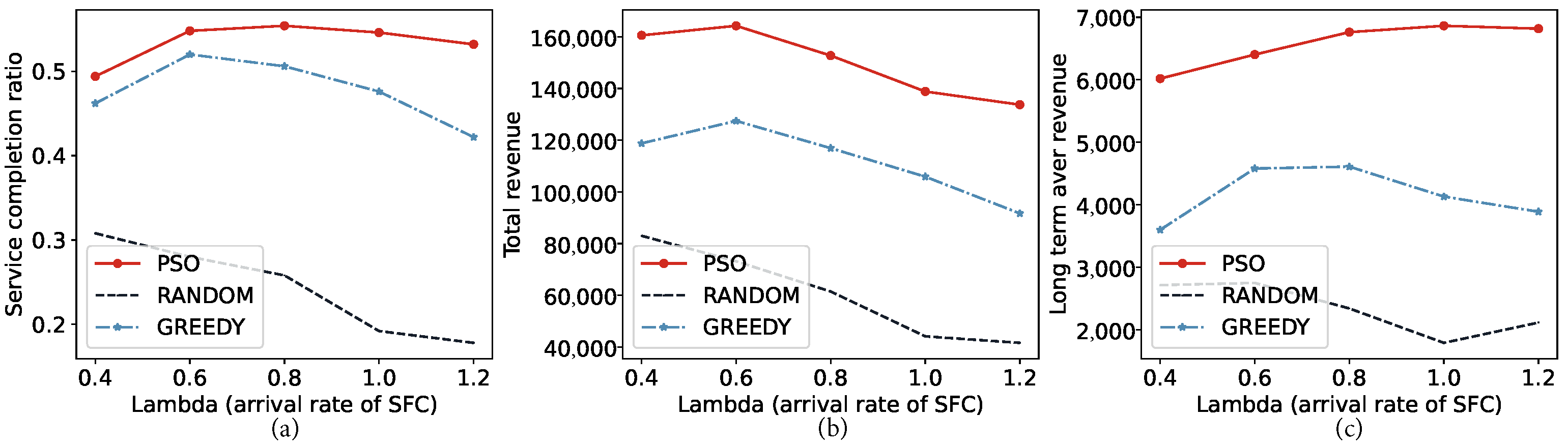
5.5. Impact of Workload
To investigate the influence of service load on the SFC embedding algorithm, we varied the SFC arrival rates for our experiments, and the results are depicted in the figure. Figure 6a illustrates the completion of the SFC as the service load gradually increases. It is evident that the PSO algorithm can maintain a stable level, while the greedy algorithm and random algorithm gradually deteriorate. This gap gradually expands with an increase in load. This phenomenon can also be observed in the total returns and long-term average returns depicted in Figure 6b,c. This result demonstrates that the PSO algorithm is capable of thoroughly exploring the solution space of the problem and offering a viable placement or migration plan, even when there are more SFC services in the network and fewer remaining resources. This also exemplifies its resource-aware ability. It should be noted that under optimal conditions, the arrival rate of SFC ultimately impacts the fluctuation of resource occupancy in the network. Hence, apart from the embedding algorithm, the bottleneck also lies in the distribution of network resources, which can result in significant random errors in experimental outcomes.
5.6. Impact on Volume of Services
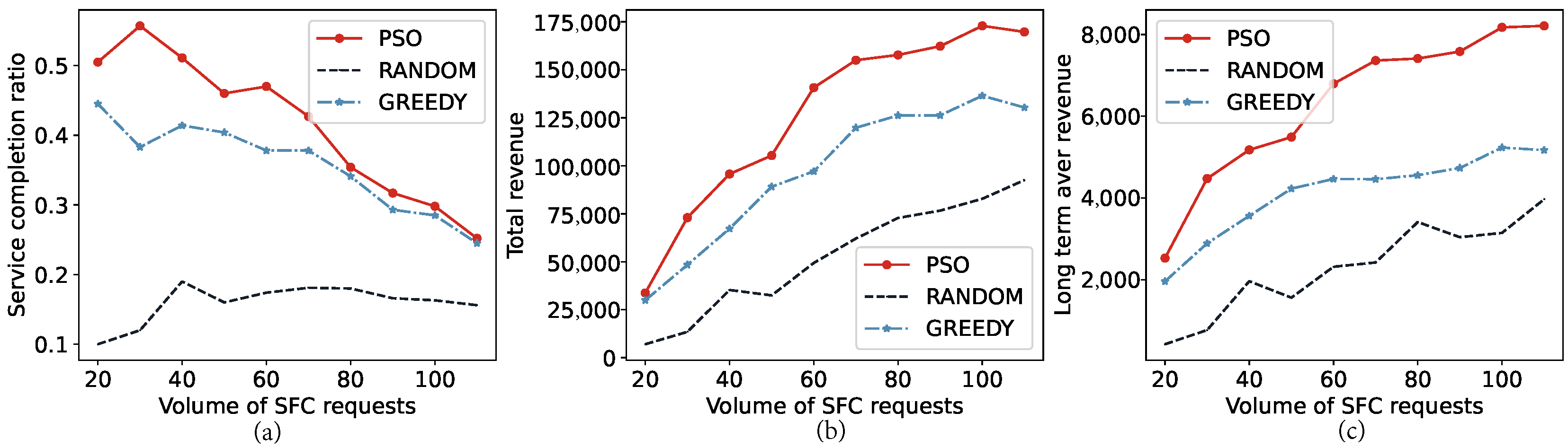
In the experiment, we are investigating the network’s capacity by using different amounts of SFC. Specifically, we gradually increase the amount of network resources requested to explore the network’s ultimate capacity. Leased resources, such as CPU, RAM, and DISK, have recyclable characteristics that result in minimal impact on the increase in the number of SFCs when the arrival rate and life cycle remain unchanged. As a result, revenue increases steadily over time. However, for consumable resources such as ENG, once the energy is depleted, the network will no longer be able to provide resources for any SFCs. As shown in Figure 7a, as the number of SFCs increases, the PSO algorithm gradually reaches the bottleneck of network resources, and the completion rate approaches that of the greedy algorithm. It can also be calculated that the maximum number of SFCs that can provide resources in the network is approximately 30. It can also be observed from the total and long-term returns in Figure 7b,c that the yield curve reaches its limit when energy resources are near exhaustion.
6. Discussion and Future Work
This paper has presented an in-depth examination of the embedding and migration of service function chaining (SFC) within a dynamic network topology, specifically a UAV network. The study focused on the comprehensive process of calculating the benefits of SFC, from its deployment to maintenance throughout its lifecycle, with the long-term average benefit as the optimization goal. The problem was formulated as an integer programming problem and addressed with a proposed SFC embedding algorithm based on the particle swarm optimization (PSO) algorithm. This algorithm provides an SFC embedding and migration scheme with reduced time costs. Experimental results demonstrated the algorithm’s ability to achieve network resource perception by leveraging the exploratory capabilities of particles, thereby efficiently utilizing network resources across varying loads, from low to high.
However, we acknowledges the limitation of the local optimal solution bottleneck of the PSO algorithm as a heuristic algorithm. Moreover, the performance of optimized deployment under given simulation settings is not presented in this paper and then compared with the used algorithm to reflect the degree of optimality of the algorithm. This is mainly because using the existing network modeling methods in dynamic scenarios, it is extremely complicated to solve the optimal deployment scheme, and this complexity is mainly related to the sequential decisions brought by considering the time factor. As far as we know, the solution of the optimal SFC embedding mode in a dynamic network environment has not been studied in the existing research. In fact, our verification experiment on network resource consumption can also demonstrate the optimality of this algorithm to a certain extent, because at the end of the simulation, the battery resource utilization rate of the UAV swarm has reached about 80%, and it is already very difficult to further deploy SFC to the network under the constraint of energy consumption. We do not yet have an offline algorithm that can tell us what the ideal limit of resource utilization is. In our recent research, modeling dynamic networks using a time extend graph (TEG) combined with maximum flow theory is a possible way to achieve this goal, which is one of our future research plans.
Future research is recommended to propose an online algorithm with similar agility but improved exploration performance, further optimizing the utilization of network resources in conjunction with the statistical law of SFC service arrival and SFC context. This approach will enable progress towards the global optimal solution. Intelligent algorithms, such as those represented by deep reinforcement learning, may be one of the potential solutions to this challenge. This study’s findings and proposed algorithm have significant implications for the field of dynamic network topology, particularly in the context of UAV networks.
Author Contributions
Conceptualization, X.W.; methodology, X.W. and S.S.; validation, S.S.; writing—original, X.W.; writing—review and editing, S.S. and C.W. All authors have read and agreed to the published version of the manuscript.
Funding
This work has received support from the National Natural Science Foundation of China under Grant 62171158 and was also supported by the Fundamental Research Funds for the Central Universities under Grant 2242022k60006.
Data Availability Statement
The data are inconvenient to directly disclose. The data presented in this study are available on request from the corresponding author.
Conflicts of Interest
The authors declare no conflicts of interest.
References
- Chaumette, S.; Kim, J.H.; Namuduri, K.; Sterbenz, J.P.G. UAV Networks and Communications; Cambridge University Press: Cambridge, UK, 2017. [Google Scholar]
- Zeng, Y.; Xu, X.; Jin, S.; Zhang, R. Simultaneous Navigation and Radio Mapping for Cellular-Connected UAV With Deep Reinforcement Learning. IEEE Trans. Wirel. Commun. 2021, 20, 4205–4220. [Google Scholar] [CrossRef]
- Qin, Y.; Guo, D.; Luo, L.; Zhang, J.; Xu, M. Service function chain migration with the long-term budget in dynamic networks. Comput. Netw. 2023, 223, 109563. [Google Scholar] [CrossRef]
- Attaoui, W.; Sabir, E.; Elbiaze, H.; Guizani, M. VNF and CNF Placement in 5G: Recent Advances and Future Trends. IEEE Trans. Netw. Serv. Manag. 2023, 20, 4698–4733. [Google Scholar] [CrossRef]
- Wijethilaka, S.; Liyanage, M. Survey on Network Slicing for Internet of Things Realization in 5G Networks. IEEE Commun. Surv. Tutorials 2021, 23, 957–994. [Google Scholar] [CrossRef]
- Wu, W.; Zhou, C.; Li, M.; Wu, H.; Zhou, H.; Zhang, N.; Shen, X.S.; Zhuang, W. AI-Native Network Slicing for 6G Networks. IEEE WIreless Commun. 2022, 29, 96–103. [Google Scholar] [CrossRef]
- Beck, M.T.; Fischer, A.; de Meer, H.; Botero, J.F.; Hesselbach, X. A distributed, parallel, and generic virtual network embedding framework. In Proceedings of the 2013 IEEE International Conference on Communications (ICC), Budapest, Hungary, 9–12 June 2013; pp. 3471–3475. [Google Scholar]
- Beck, M.T.; Botero, J.F. Coordinated Allocation of Service Function Chains. In Proceedings of the 2015 IEEE Global Communications Conference (GLOBECOM), San Diego, CA, USA, 6–10 December 2015. [Google Scholar] [CrossRef]
- Tomassilli, A.; Giroire, F.; Huin, N.; Pérennes, S. Provably Efficient Algorithms for Placement of Service Function Chains with Ordering Constraints. In Proceedings of the IEEE INFOCOM 2018—IEEE Conference on Computer Communications, Honolulu, HI, USA, 16–19 April 2018; pp. 774–782. [Google Scholar] [CrossRef]
- Sallam, G.; Gupta, G.R.; Li, B.; Ji, B. Shortest path and maximum flow problems under service function chaining constraints. In Proceedings of the IEEE Infocom 2018—IEEE Conference on Computer Communications, Honolulu, HI, USA, 16–19 April 2018; pp. 2132–2140. [Google Scholar]
- Jin, P.; Fei, X.; Zhang, Q.; Liu, F.; Li, B. Latency-aware VNF chain deployment with efficient resource reuse at network edge. In Proceedings of the IEEE INFOCOM 2020—IEEE Conference on Computer Communications, Toronto, ON, Canada, 6–9 July 2020; pp. 267–276. [Google Scholar]
- Zheng, D.; Peng, C.; Liao, X.; Cao, X. Toward optimal hybrid service function chain embedding in multiaccess edge computing. IEEE Internet Things J. 2019, 7, 6035–6045. [Google Scholar] [CrossRef]
- Zheng, D.; Peng, C.; Liao, X.; Tian, L.; Luo, G.; Cao, X. Towards latency optimization in hybrid service function chain composition and embedding. In Proceedings of the IEEE INFOCOM 2020—IEEE Conference on Computer Communications, Toronto, ON, Canada, 6–9 July 2020; pp. 1539–1548. [Google Scholar]
- Dimolitsas, I.; Dechouniotis, D.; Papavassiliou, S. Time-efficient distributed virtual network embedding for round-trip delay minimization. J. Netw. Comput. Appl. 2023, 217, 103691. [Google Scholar] [CrossRef]
- Vidal, I.; Nogales, B.; Valera, F.; Gonzalez, L.F.; Sanchez-Aguero, V.; Jacob, E.; Cervelló-Pastor, C. A multi-site NFV testbed for experimentation with SUAV-based 5G vertical services. IEEE Access 2020, 8, 111522–111535. [Google Scholar] [CrossRef]
- Carpio, F.; Bziuk, W.; Jukan, A. On optimal placement of hybrid service function chains (SFCs) of virtual machines and containers in a generic edge-cloud continuum. arXiv 2020, arXiv:2007.04151. [Google Scholar]
- Carpio, F.; Bziuk, W.; Jukan, A. Scaling migrations and replications of virtual network functions based on network traffic forecasting. Comput. Netw. 2022, 203, 108582. [Google Scholar] [CrossRef]
- Rui, L.; Chen, X.; Gao, Z.; Li, W.; Qiu, X.; Meng, L. Petri Net-Based Reliability Assessment and Migration Optimization Strategy of SFC. IEEE Trans. Netw. Serv. Manag. 2021, 18, 167–181. [Google Scholar] [CrossRef]
- Bai, J.; Chang, X.; Rodríguez, R.J.; Trivedi, K.S.; Li, S. Towards uav-based mec service chain resilience evaluation: A quantitative modeling approach. IEEE Trans. Veh. Technol. 2023, 72, 5181–5194. [Google Scholar] [CrossRef]
- Hu, Y.; Min, G.; Li, J.; Li, Z.; Cai, Z.; Zhang, J. VNF Migration in Digital Twin Network for NFV Environment. Electronics 2023, 12, 4324. [Google Scholar] [CrossRef]
- Boutin, E.; Ekanayake, J.; Lin, W.; Shi, B.; Zhou, J.; Qian, Z.; Wu, M.; Zhou, L. Apollo: Scalable and coordinated scheduling for cloud-scale computing. In Proceedings of the 11th USENIX Conference on Operating Systems Design and Implementation, Broomfield, CO, USA, 6–8 October 2014; pp. 285–300. [Google Scholar]
- Schneider, S.; Sharma, A.; Karl, H.; Wehrheim, H. Specifying and Analyzing Virtual Network Services Using Queuing Petri Nets. In Proceedings of the 2019 IFIP/IEEE Symposium on Integrated Network and Service Management (IM), Arlington, VA, USA, 8–12 April 2019; pp. 116–124. [Google Scholar]
- Li, J.; Wang, R.; Wang, K. Service Function Chaining in Industrial Internet of Things With Edge Intelligence: A Natural Actor-Critic Approach. IEEE Trans. Ind. Inform. 2023, 19, 491–502. [Google Scholar] [CrossRef]
- Su, S.; Zhang, Z.; Liu, A.X.; Cheng, X.; Wang, Y.; Zhao, X. Energy-Aware Virtual Network Embedding. IEEE/ACM Trans. Netw. 2014, 22, 1607–1620. [Google Scholar] [CrossRef]
- Wang, T.; Fan, Q.; Li, X.; Zhang, X.; Xiong, Q.; Fu, S.; Gao, M. DRL-SFCP: Adaptive Service Function Chains Placement with Deep Reinforcement Learning. In Proceedings of the ICC 2021—IEEE International Conference on Communications, Montreal, QC, Canada, 14–23 June 2021; pp. 1–6. [Google Scholar] [CrossRef]
- Rost, M.; Schmid, S. On the Hardness and Inapproximability of Virtual Network Embeddings. IEEE/ACM Trans. Netw. 2020, 28, 791–803. [Google Scholar] [CrossRef]
- Kennedy, J.; Eberhart, R. Particle swarm optimization. In Proceedings of the ICNN’95—International Conference on Neural Networks, Perth, WA, Australia, 27 November–1 December 1995; Volume 4, pp. 1942–1948. [Google Scholar] [CrossRef]
- Clerc, M.; Kennedy, J. The particle swarm—Explosion, stability, and convergence in a multidimensional complex space. IEEE Trans. Evol. Comput. 2002, 6, 58–73. [Google Scholar] [CrossRef]
- Castillo-Lema, J.; Venâncio Neto, A.; de Oliveira, F.; Takeo Kofuji, S. Mininet-NFV: Evolving Mininet with OASIS TOSCA NVF profiles Towards Reproducible NFV Prototyping. In Proceedings of the 2019 IEEE Conference on Network Softwarization (NetSoft), Paris, France, 24–28 June 2019; pp. 506–512. [Google Scholar] [CrossRef]
Figure 1.
Deployment of VNFs on the UAV IoT to enable network slicing and support the SFC.

Figure 2.
SFC embedding and migration simulation framework based on MANO.

Figure 3.
Simulation model workflow.

Figure 4.
Dynamic diagram illustrating changes in network resource utilization: (a) CPU resource; (b) RAM resource; (c) DISK resource; (d) energy resource.
Figure 4.
Dynamic diagram illustrating changes in network resource utilization: (a) CPU resource; (b) RAM resource; (c) DISK resource; (d) energy resource.

Figure 5.
Comparison of SFC algorithm embedding performance under different frequencies of topological changes: (a) comparison of SFC completion rates; (b) comparison of total system revenue; (c) comparison of long-term average revenue.
Figure 5.
Comparison of SFC algorithm embedding performance under different frequencies of topological changes: (a) comparison of SFC completion rates; (b) comparison of total system revenue; (c) comparison of long-term average revenue.

Figure 6.
Comparison of SFC algorithm embedding performance under different arrival rates of SFCs: (a) comparison of SFC completion rates; (b) comparison of total system revenue; (c) comparison of long-term average revenue.
Figure 6.
Comparison of SFC algorithm embedding performance under different arrival rates of SFCs: (a) comparison of SFC completion rates; (b) comparison of total system revenue; (c) comparison of long-term average revenue.

Figure 7.
Comparison of SFC algorithm embedding performance under different volumes of SFCs: (a) comparison of SFC completion rates; (b) comparison of total system revenue; (c) comparison of long-term average revenue.
Figure 7.
Comparison of SFC algorithm embedding performance under different volumes of SFCs: (a) comparison of SFC completion rates; (b) comparison of total system revenue; (c) comparison of long-term average revenue.


Table 1.
Notation and definitions.
| Notation | Definition |
|---|---|
| Set of substrate network nodes | |
| Each physical node in substrate network | |
| Set of substrate network links at time t | |
| Each physical link between node and node at time t | |
| Maximum resource capacity of node | |
| Remaining resource of node at time t | |
| Maximum resource capacity of link | |
| Remaining resource of link at time t | |
| “Wait-Time Matrix” for servers in physical node 1 | |
| Set of SFCs to be processed | |
| Set of virtual network nodes (VNFs) of SFC | |
| Each virtual node in SFC | |
| Set of virtual network links of SFC | |
| Each virtual link between VNF and VNF | |
| Resource need to be allocated of VNF | |
| Resource need to be allocated of virtual link | |
| ,, | Arrival time, life cycle, and end time of SFC |
| Transmission latency requirement of SFC | |
| Set of mapping indication between VNF in SFCf and physical node at time t | |
| Whether VNF is deployed on physical node at time t | |
| Set of mapping indication between virtual link in SFCf and physical link at time t | |
| Whether virtual link is embedded in physical link at time t | |
| , , , | Total latency, operation latency, remap and reroute latency of SFC at time t |
| System revenue of SFC |
1 Boutin et al. [13] defines the latency matrix for servers.
Disclaimer/Publisher’s Note: The statements, opinions and data contained in all publications are solely those of the individual author(s) and contributor(s) and not of MDPI and/or the editor(s). MDPI and/or the editor(s) disclaim responsibility for any injury to people or property resulting from any ideas, methods, instructions or products referred to in the content. |
© 2024 by the authors. Licensee MDPI, Basel, Switzerland. This article is an open access article distributed under the terms and conditions of the Creative Commons Attribution (CC BY) license (https://creativecommons.org/licenses/by/4.0/).
Share and Cite
MDPI and ACS Style
Wang, X.; Shi, S.; Wu, C. Research on Service Function Chain Embedding and Migration Algorithm for UAV IoT. Drones 2024, 8, 117. https://0-doi-org.brum.beds.ac.uk/10.3390/drones8040117
AMA Style
Wang X, Shi S, Wu C. Research on Service Function Chain Embedding and Migration Algorithm for UAV IoT. Drones. 2024; 8(4):117. https://0-doi-org.brum.beds.ac.uk/10.3390/drones8040117
Chicago/Turabian StyleWang, Xi, Shuo Shi, and Chenyu Wu. 2024. "Research on Service Function Chain Embedding and Migration Algorithm for UAV IoT" Drones 8, no. 4: 117. https://0-doi-org.brum.beds.ac.uk/10.3390/drones8040117