
A Versatile Deposition Model for Natural and Processed Surfaces


Institute of Thermal Turbomachinery, Karlsruhe Institute of Technology (KIT), 76137 Karlsruhe, Germany
*
Author to whom correspondence should be addressed.
Dynamics 2024, 4(2), 233-253; https://0-doi-org.brum.beds.ac.uk/10.3390/dynamics4020014
Submission received: 31 January 2024
/
Revised: 17 March 2024
/
Accepted: 28 March 2024
/
Published: 30 March 2024
Abstract
:This paper introduces a robust deposition model designed for exploring the growth dynamics of deposits on surfaces under practical conditions. The study addresses the challenge of characterizing the intricate morphology of deposits, exhibiting significant visual variations. A generative approach is deployed to create diverse natural and engineered surface textures, governed by probabilistic principles. The model’s formulation addresses key questions related to deposition initiation, nucleation point behaviour, spatial scaling, deposit growth rates, spread dynamics, and surface mobility. A versatile algorithm, relying on six parameters and employing nested loops and Gaussian sampling, is developed. The algorithm’s efficacy is examined through extensive simulations, involving variations in nucleation scaling densities, aggregate scaling scenarios, spread factors, and diffusion rates. Surface statistics are computed for simulated deposits and analyzed using Fast Fourier Transform (FFT). The resulting database enables quantitative comparisons of surfaces generated with different parameters, where the database-derived parallel coordinates offer guidance for selecting optimal model parameters to achieve desired surface morphologies. The proposed approach is validated against urea-derived deposits, exhibiting statistical consistency and agreement with experimental observations. Overall, the model’s adaptable framework holds promise for understanding and predicting deposit growth on surfaces in diverse practical scenarios.
1. Introduction
Kinetic interface roughening refers to the dynamic evolution of interfaces or boundaries between different phases or materials over time, resulting in changes in their roughness. This process is often characterized by the interplay of growth mechanisms, stochastic fluctuations, and the influence of external factors, leading to the development of complex and irregular surface patterns. These processes are prevalent in a wide range of natural and engineered systems, contributing to the formation of diverse surface patterns. Examples include the growth of crystal surfaces [1], the development of thin films [2], the advancement of biological fronts such as bacterial colonies [3], coffee stains, density of birds on a wire [4], sedimentary rock formations [5], the progression of chemical reaction fronts, and DNA walk [6]. The roughening of interfaces is influenced by both deterministic and stochastic factors. Deterministic factors may include the inherent growth mechanisms and physical properties of the materials involved, while stochastic factors introduce randomness and fluctuations that affect the evolving interface. The combination of these factors gives rise to intriguing phenomena such as self-affine or self-similar interface profiles and the emergence of power-law behaviours in the spatial and temporal statistical properties of the evolving surfaces.
Sequential random packing could be considered as one of the earliest attempts to describe growth dynamics [7]. Given a one-dimensional space, the goal is to sequentially place objects along this line in a random manner. Once an object is placed, it occupies a certain length along the line, and subsequent objects must be placed without overlapping the existing ones. The term random indicates that the placement of each object is not predetermined or planned; rather, it is subject to some form of stochastic or probabilistic process. The mono-layered surface, in such a case, will saturate asymptotically to a constant, 0.74759. In parallel, Vold pioneered the formal particle deposition models for the sediment formation application, where particles are added one at a time to a two-dimensional surface with randomly selected linear ballistic trajectories [8]. Herein, the angle on trajectory could be either at a prescribed angle [9], normal to the surface, or selected randomly on a flat or inclined surface [10,11,12]. The extensively examined iteration of this ballistic deposition (BD) model involves the use of pixel-like particles with uniform sizes, creating clusters characterized by sophisticated porous structures, often articulated in terms of fractal dimensionality. Herein, a crucial distinction lies in how the deposited particle becomes immobilized upon contacting either another particle or the underlying surface. In simple ballistic models, the particle dropped in the ith column can adhere upon initially reaching a lattice site with one or more neighboring sites already occupied [13]. A further level of complexity was later introduced by considering low-temperature diffusion [14,15]. In this case, the deposited particle surveys the surface sites at nearest-neighbor coordinates (), assessing which one provides the strongest binding, i.e., the highest number of occupied neighbors. The particle then relocates to this site and adheres accordingly. This modification allowed better agreement with the linear generalized Langevin equation [16] for growth with surface diffusion [14]. If the particles are nonsticky, on the other hand, dropped particles deposit at the lowest position along its trajectory (i.e., random deposition (RD)). As a result, deposition structure contains no voids and is compact. Further studies extended the ballistic deposition algorithm for next-nearest-neighbour interactions [17], binary particles with different diffusion/stickiness characteristics [18,19,20], hybrid models with random deposition [21,22], particles of different sizes and shapes [23,24,25,26,27,28,29,30,31], triangular lattice with relaxation [32], more complex sticking probability schemes [33,34,35,36,37], including surface restructuring [38], and radial diffusion [39].
In summary, the exploration of kinetic interface roughening, which encompasses the dynamic evolution of interfaces or boundaries between different phases or materials, has been a subject of considerable interest due to its relevance in various natural and engineered systems. This dynamic process leads to the development of intricate and irregular surface patterns, influenced by growth mechanisms, stochastic fluctuations, and external factors. The significance of understanding these phenomena is underscored by their prevalence in diverse contexts. In contrast to the wealth of deposit models focusing on scaling behaviors, however, practical applications may demand a pragmatic approach. In many instances, we possess knowledge about the desired properties of a surface, such as roughness or porosity, but lack a suitable model to generate structures aligning with these specifications. This gap necessitates the development of a general model capable of creating surfaces with predefined properties, facilitating integration with mathematical models or parametric studies for practical applications. In this context, our paper makes a significant contribution by introducing a robust deposition model that adopts a top-down approach, utilizing a minimal set of parameters to generate diverse surface morphologies. The model’s versatility lies in its capacity to mimic the sub-physics of the deposit formation process, serving as a valuable tool for researchers and practitioners seeking to create surfaces with specific properties for coupling with mathematical models or parametric studies. Our approach provides a systematic and adaptable framework, as demonstrated through extensive simulations and validation against urea-derived deposits.
The subsequent sections of this paper delve into the underlying theory behind the deposition models, followed by a detailed description of the proposed algorithm. We further provide insights into a case study that validates the efficacy of the proposed algorithm, followed by an exploration of the impact of model parameters on deposit morphology and the presentation of proof-of-concept study results. The paper concludes with a summary of key findings and conclusions, emphasizing the broader applicability and significance of the developed deposition model for practical scenarios.
2. Theory and Methods
2.1. Modeling Interface Growth in the Kardar-Parisi-Zhang Universality Class
A universality class is a concept in statistical physics that groups together different physical systems exhibiting similar macroscopic behavior, despite differences in their microscopic details. In the context of interface growth, the Kardar–Parisi–Zhang (KPZ) universality class describes a broad category of systems with universal scaling properties [40].
At its core, the KPZ universality class is described by a stochastic partial differential equation that captures the dynamic evolution of an interface under the influence of random fluctuations. Consider a one-dimensional interface described by the height function , where x represents the spatial coordinate and t the time. The KPZ equation for such a system is given by [41]
where
- is time under the derivative of the height function;
- is the surface tension, or diffusion term smoothing the interface,
- is a nonlinear term capturing the local curvature of the interface, promoting the growth in regions with significant local curvature;
- is the Gaussian white noise term representing random fluctuations.
The scaling parameters and can be heuristically calculated for a particular case study.
The roughness of a growing interface, denoted as , characterizes the deviation of the surface from its average height:
where L is the characteristic system size. In the KPZ universality class, the roughness typically increases as a power of time, expressed as
where is the growth exponent. This scaling behavior indicates that the surface becomes increasingly rough over time, with the rate of roughening determined by the specific value of for the given system. As time progresses, the roughness of the surface may exhibit saturation, reaching a plateau value that depends on the system size. This saturation behavior is often expressed as
where is the saturation exponent. The saturation value of the roughness increases as a power of the system size, reflecting the influence of the overall dimensions of the system on the final state of the interface.
The model has attracted much scientific interest on a variety of problems, as highlighted in the introduction section. Although presenting any rigorous analytic treatment is beyond the scope of this paper, we will discuss simple discrete models to lay out the ground work of the proposed methodology. For a more comprehensive theoretical exploration, interested readers are directed to the works of Takeuchi [41] and Corwin [42], where deeper analytical discussions and theoretical insights into KPZ universality can be found in the related literature.
2.2. Random Versus Ballistic Deposition Models
Within the scope of stochastic models governing interface growth, a comparative exploration between random and ballistic deposition unveils fundamental distinctions in their underlying growth mechanisms, which is necessary to revisit before describing the proposed methodology. Random deposition (RD) is one of the simplest models capturing the essence of a randomly evolving interface. The process unfolds as individual blocks descend independently and concurrently onto substrate sites. The stochastic evolution of the interface height function can be described by the following discrete Markov process for a dropped particle size of unity:
Herein, represents a random variable that equals 1 with probability p and 0 with probability . models the stochastic nature of block deposition for independent column i for event j. The sampled probabilities for event j can be interpreted as exponential waiting times, leading to the central limit theorem. In other words, as the number of deposition events increases, the sum of these independent, identically distributed waiting times converges to a Gaussian distribution. Consequently, the height fluctuations of the interface exhibit Gaussian behavior, a characteristic feature of the Gaussian universality class.
Ballistic deposition (BD), on the other hand, introduces spatial correlations, deviating from the inherent independent randomness of the RD. In this approach, particles again fall similarly, but adhere upon their contact with the neighbouring particle, and/or the substrate:
In this simple formulation, the sticking probability is is assumed to 1, and neighbour search is limited to a unit distance. In more recent implementations, such events are also approximated with prior probability distribution [33,34,35,36,37], resulting in more complex behaviours. In this context, RD can be considered as a BD model with sticking probability of zero. This simple yet powerful mechanism results in the formation of porous structures and overhangs, defining the height function as the maximum height above x occupied by a block of deposit.
It is worth noting here that the BD model shares essential characteristics with the KPZ universality class, forming a connection between microscopic deposition dynamics and macroscopic features encapsulated by the KPZ equation. In the BD model, the height changes are locally determined, relying solely on the heights of neighboring sites. Similarly, in the KPZ equation, the growth of the interface at a given point is nonlinearly influenced by the local slope, emphasizing the significance of nearby heights. Additionally, the rapid filling of large valleys, promoting surface uniformity, aligns with the smoothing tendencies observed in KPZ-like growth phenomena. BD model also exhibits growth driven by noise that rapidly decorrelates both spatially and temporally, in line with the stochastic dynamics typical of the KPZ universality class. Interestingly, the KPZ equation itself emerges as a continuous limit of the discrete BD process, elucidating the shared mathematical underpinnings.
2.3. Proposed Top-Down Modelling Approach
The objective of this study is to devise a robust model capable of generating diverse surface morphologies while utilizing a minimal set of parameters. To achieve this objective, we adopt a top-down approach, as illustrated in Figure 1. The initiation of this process involves defining the global specifications of the surface, encompassing parameters such as surface roughness, the slope of the power spectra density, and optionally, the porosity and pore size distribution. In essence, our modeling strategy aims to commence with a generalized deposit formation model, and through parameter selection, mimic the sub-physics of the deposit formation process in a reverse engineering fashion.
The following subsection delineates the proposed algorithm, with the descriptions of the model parameters. Then, we explain simulated cases within a parametric sweep study, systematically constructing a target library. This library proves instrumental in facilitating parameter tuning for diverse use case scenarios. Finally, a proof-of-concept study is detailed to test the proposed methodology.
2.3.1. Algorithm
The quality of our model lies in its generative nature, intending to produce varied natural or engineered surfaces that are unique in each run, thereby yielding a distinct height distribution profile. This necessitates the adoption of a probabilistic framework, steering away from deterministic solutions. A crucial consideration in this pursuit is the “creativity” problem, where the model’s outcomes should be statistically consistent. To address this challenge, our model algorithm imposes constraints on the infinite possibility space by incorporating a predefined set of rules rooted in the physics of the deposition problem.
To determine the mathematical form of the governing equations and the resulting algorithm, we posed several key questions: (i) How is the deposition process initiated? (ii) Can the initialization be approximated as nucleation points, serving as origins for deposit growth propagation? (iii) Do nucleation points scale with the dimensions of the solution domain? (iv) What are the relative lifetimes of nucleation events – do they occur simultaneously or exhibit varying durations? (v) Do we anticipate variations in the relative deposit growth rates across different spatial coordinates? (vi) To what extent does the deposit growth spread over the surface? (vii) Is there a notable surface mobility? By exploring alternative approaches, we arrived at a versatile algorithm (Figure 2) that adeptly addresses these considerations and demonstrates efficacy in capturing the intricacies of the deposition process.
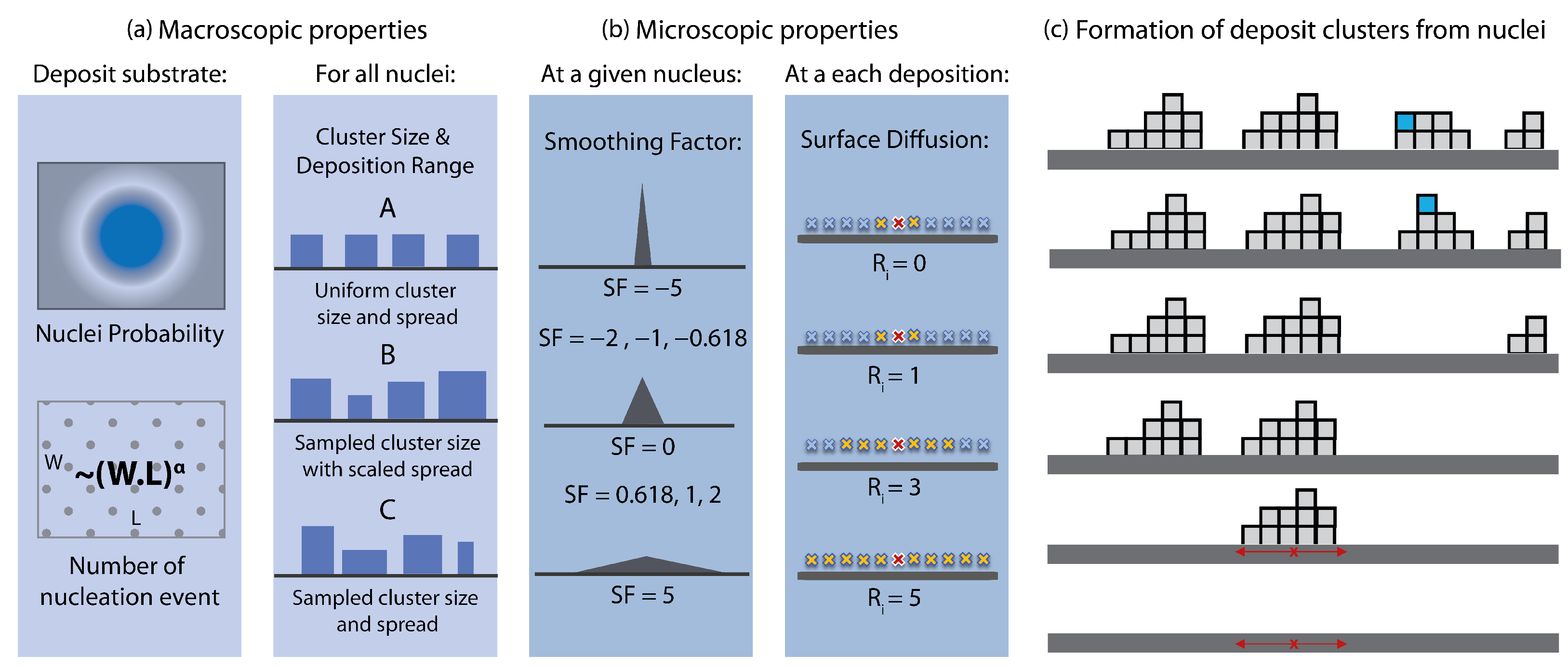
The backbone model is based on the terms governing the KPZ class (Equation (1)) with a sticking probability of zero (i.e., RD). Nonetheless, instead of depositing individual particles of unit size, the deposition process is governed by nucleation points and evolves as deposition of clusters (Figure 3). The nuclei can be considered as attractors originating from the physics of the problem, such as supersaturated solutions [43]. Herein, the nuclei can be homogeneously, or heterogeneously distributed over the substrate surface. As a result of this cluster-based approach, the model inherently gains properties that can be tuned at macroscopic level (Figure 3a), such as (i) the locations of nuclei, which can be coded as a surface property and passed down to model as a filter, (ii) scalability of number of nuclei with the substrate size, (iii) variable cluster size and size distribution, (iv) variable cluster aspect ratio (i.e., spread of nucleation event) and (v) pore and pore size distributions.
In the presented model, nucleation event density is scaled with the size of the substrate , where is the nucleation density parameter. The homogeneity of the process time distribution for deposit formation (i.e., how long each event takes) and the spread of the deposit clusters are defined by another parameter, cluster group. In particular, Class A refers to the uniform amount deposit formation with the same spread characteristics for all nuclei, typically yielding symmetric surfaces with uniform properties. Class B denotes the same spread behaviour for all nuclei, but with different process times. In the code, these process times were sampled from Gaussian distributions. Class C refers to cases with varying process times and spread dynamics, both sampled from Gaussian distributions (Figure 3a).
For a given nucleation point, particles are dropped via RD within a radius of influence around the nucleus. This event can be considered as a micro random deposition process. Figure 3c depicts four cluster formations with RD. The spread dynamics of each nucleus (marked with red for the first cluster) is defined by a smoothing factor, which changes the radius of influence of the random deposition process (Figure 3b). Another micro-parameter is the surface diffusion, related to the first term of the KPZ equation. If allowed, the model checks the neighbours within a radius for surface relaxation (Figure 3b). The process is depicted in Figure 3c for the fourth deposited cluster. When the last blue particle is dropped, it slides down to a the lower position on the left when .
In the base model (Figure 2), the simulation starts with the definition of the model parameters: substrate dimensions , scaling factor for nucleation density , amount of particles to drop in terms of average height H, size of a particle , cluster group , smoothing factor and surface relaxation radius . Then, the number of nuclei is calculated from
Next, the number of dropped particles per cluster i is determined as follows for cluster group A and B, C, respectively:
Then, a random location p is selected for nucleation event n. This is followed by the calculation of the radius of influence () via smoothing factor :
In the current work, we set as for Group and for Group , respectively. During the model development phase, we found heuristically that the resulting surfaces are much more consistent and natural when such parameters are based on the golden ratio. Once is calculated for the nucleation event n, we first create a list of coordinates within the by drawing a circle around the coordinate p. Then, within a for loop, particles are dropped randomly to the enlisted coordinates. If surface diffusion parameter , then we create a sub-list of neighbours within , and check for surface diffusion/relaxation and the particle is shifted to the lowest position within . This inner loop continues until all the particles are dropped in the micro-RD loop for the cluster n nucleated at position p. For more details, readers are encouraged to review the code example provided in Supplementary Material S1, which also incorporates a visual representation of the deposition process in the form of a rendered video.
As discussed in Section 2.2, RD model is not capable of creating porous surfaces like the BD model. In this work, we introduce porosity as a macroscopic property of the surface, which is represented as a particle type in the RD model. Herein, the objective is not to simulate the pore development, but to integrate known material properties like porosity and pore size distribution to the deposition model for pragmatic purposes, such as calculation of the effective thermal conductivity or permeability of a 3D object is a tandem modelling study. As the RD relies on stochastic sampling of many events, by defining the type of a particle, one can also develop complex pore structures without introducing further complexity. Herein, particle type is assigned with a probability distribution based on the porosity parameter. In particular, we experimented with different pore size distributions, aspect ratios and macro/micro pore types. All based on simple stochastic sampling principles from a priori assigned pore size distribution, assumed to be collected via experimental methods. More details can be found in the sample codes provided in Supplementary Material S1.
2.3.2. Proof-of-Concept Study and the Target Library
In a previous work [1], we identified a unique morphology of urea-derived deposits within selective catalytic reduction (SCR) systems, exhibiting self-affine surfaces and a consistent power-law distribution. Our subsequent investigation further illustrated similar deposit characteristics during the crystallization of individual urea water solution droplets [43]. Importantly, we observed nuanced variations in deposition dynamics influenced by the surface properties, which in turn results in distinct deposition regimes. This led us to question the possibility of effectively characterizing and modeling the dynamics governing such processes. Given the inherent difficulty in predicting growth dynamics for a particular problem in advance, we developed and fine-tuned the proposed algorithm (Figure 2) capable of generating intricate surface textures with a minimal set of parameters (Figure 3).
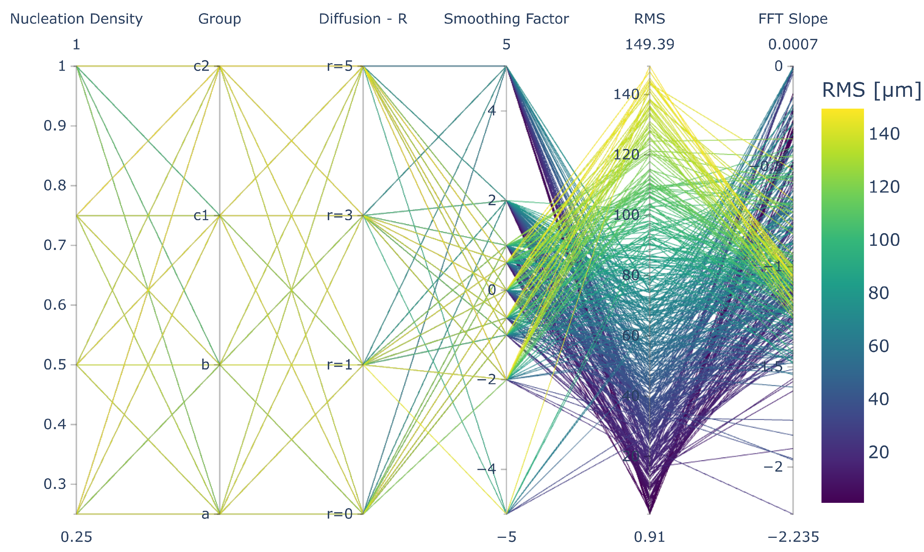
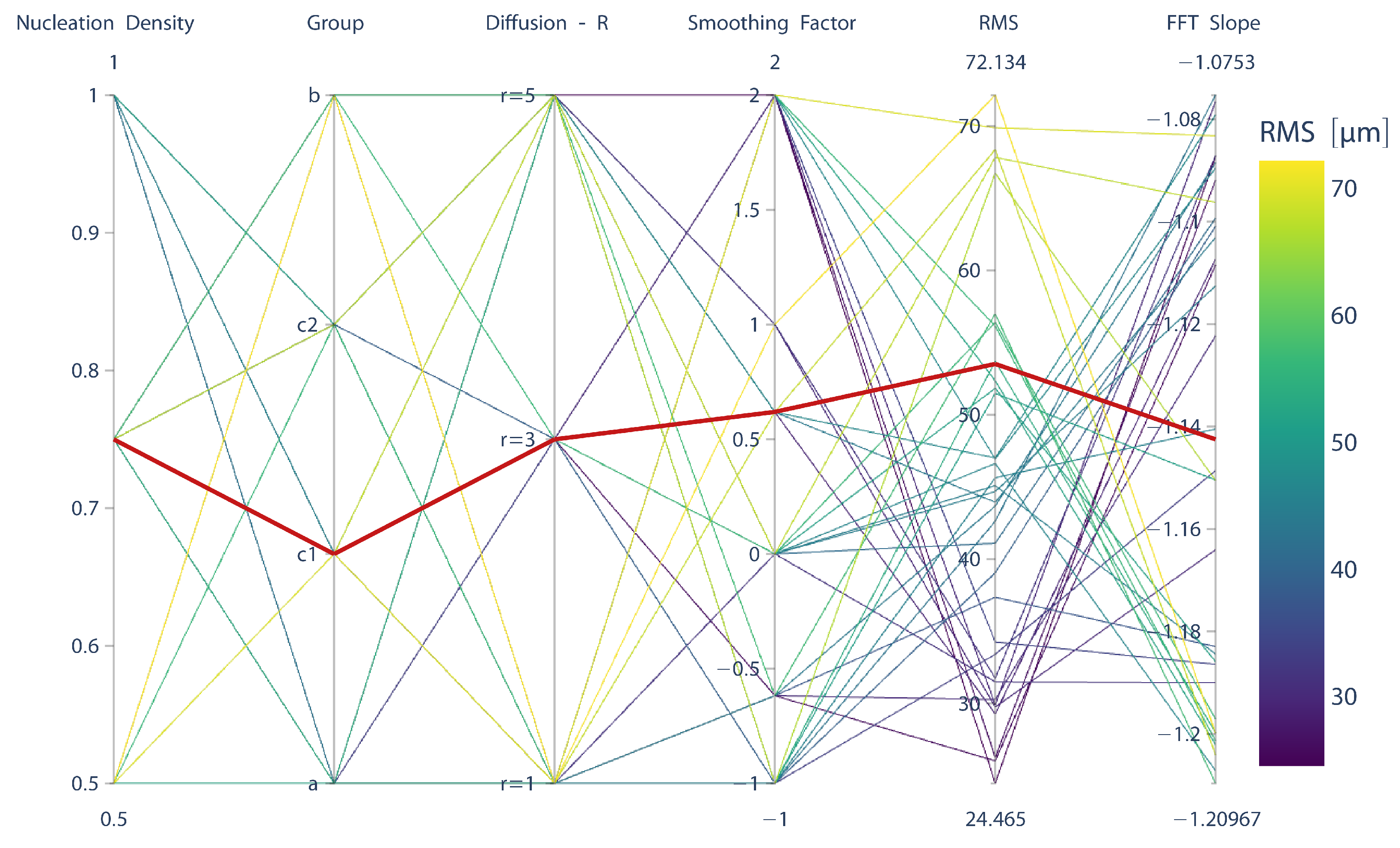
In order to analyze the influence of the model parameters on the resulting surface morphology, we tested 4 nucleation scaling densities (), 4 aggregate scaling scenarios (i.e., cluster groups ), 9 smoothing factors (), and 4 diffusion rates () over 1000 × 1000 unit length planes (W × L) with a high total deposition volume (i.e., H) ensuring surface saturation. In the next step, we calculated the surface statistics for all simulated deposits and applied Fast Fourier Transform (FFT), which together constitute a target library for the quantitative comparison of the surfaces generated with different parameters (Figure 1). In particular, the database was used to generate a guideline in the form of an interactive parallel coordinates (Figure 4 was used to select the proper model parameters leading to the desired surface morphology, which can be found in Supplementary Material S2).
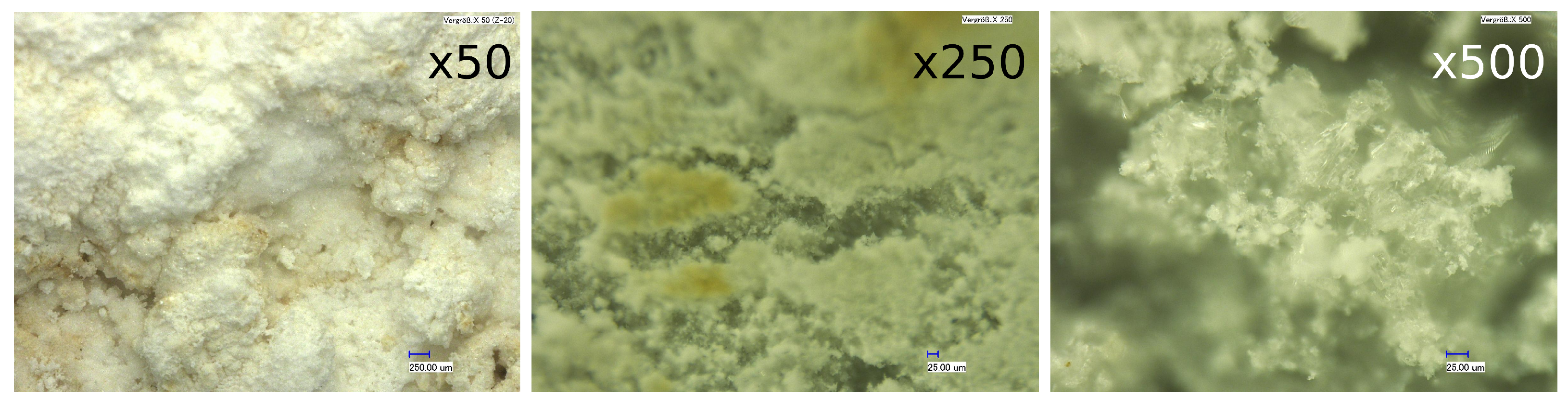
To assess the utility and the statistical consistency of our approach, we used surface height profile measurements of urea deposits generated under practically relevant conditions. To capture high-resolution data on the deposit topology, we utilized an optical profilometer (Sensofar Plμ Neox) in confocal measurement mode. In this setup, the sample underwent vertical scanning in incremental steps, ensuring that every point on the surface passed through the focus. The measurements presented in this study employed a 10× confocal objective, resulting in a field of view measuring 1270 μm × 950 μm with a spatial sampling interval of 1.66 μm. The achieved vertical resolution is smaller than 50 nm [1]. The measurements, conducted in replicates (n = 50), revealed (i) an interface width of 50 μm with a standard deviation of 26 μm, and (ii) an averaged slope of for the corresponding power spectral density (PSD) functions. For further details on the measurements and FFT computations, refer to [1]. Figure 5 illustrates images of urea deposit samples at three different magnifications, providing a detailed view of the urea deposits under optical microscopy. By using these target variables (RMS and slope), we identify the corresponding model parameters and run 400 simulations to analyze the variations in the generated surface topology.
3. Results
3.1. Impact of Model Parameters on the Generated Deposit Morphology
The objective of this study is to create a robust deposition model, which can be utilized to generate surface structures with the desired macroscopic properties such as surface roughness, or the scaling behaviour of the surface deposits (i.e., shape and slope of the PSD curve). This is carried out by a top-down, data driven approach (Figure 1, where the macroscopic target variables that can be easily measured (roughness, PSD curve characteristics) is used to select model parameters. To create the necessary parameter space library, the deposition model is run with 576 different parameter combinations over four features: nucleation density parameter α, macroscopic scaling group (A,B,C), diffusion radius R and smoothing factor (see Section 2.3.1 and Figure 3 for details). The resulting target variables are illustrated for 150 μm is shown in Figure 4.
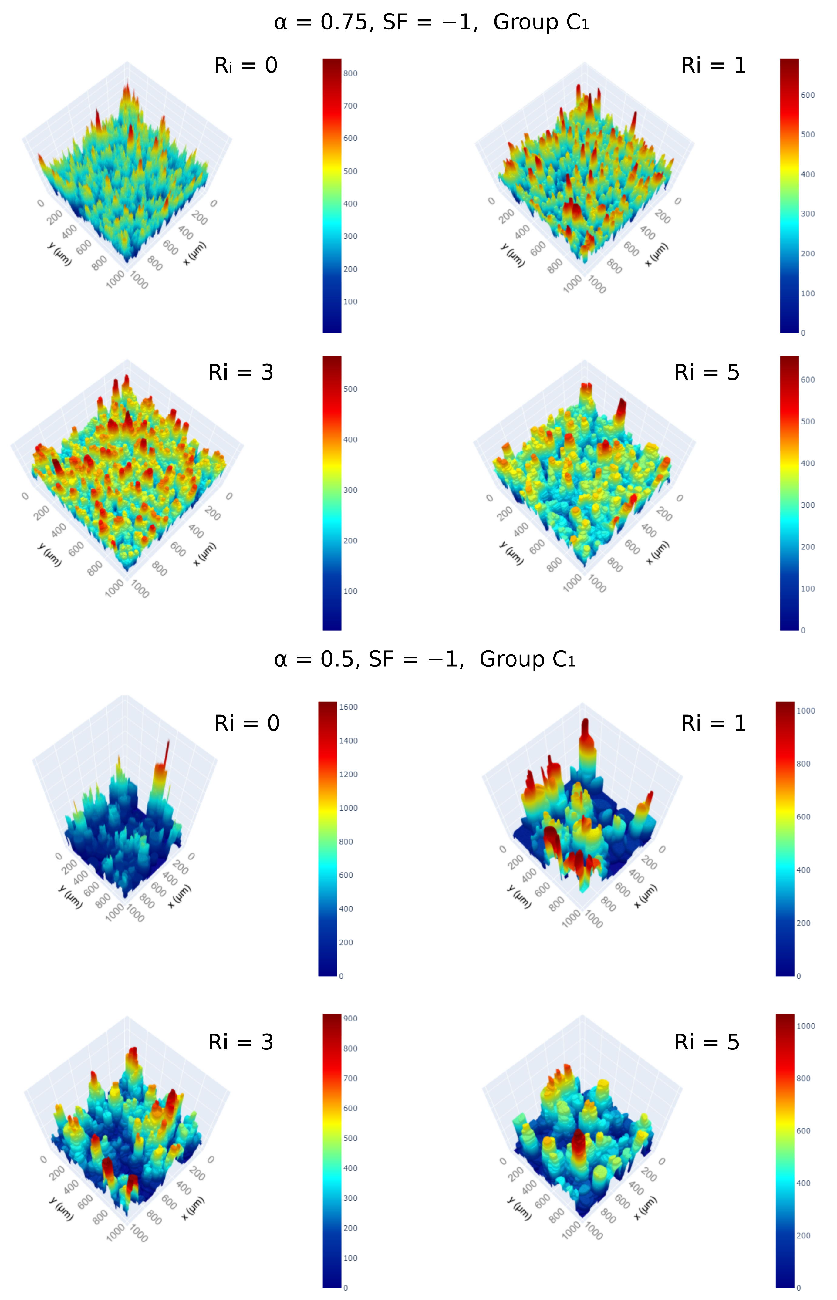
One macroscopic parameter of the model is the cluster type (Figure 3), which determines both (i) the distribution of process times and (ii) the macroscopic spread of deposit nucleation events. In the current model, we have defined four modes: (i) A, where nucleation events have the same spatial spread and deposits have the same volume; (ii) B, where nucleation events have the same spread dynamics but different sizes (hence different process times); and (iii) C, the cluster type where both spread and volume are sampled via a distribution. The generated deposits for two sets of parameters are shown in Figure 6. As expected, developed clusters become more heterogeneously distributed with Group C, while Group B enables the emergence of similar structures with different sizes or process times.
The impact is more easily observed when comparing the saturated surface roughness profiles and the corresponding PSD for different cluster types, as depicted in Figure 7 and Figure 8, respectively. At smaller smoothing factors, the micro-scale nucleation events have very small radii, creating a very spiky landscape. When deposits have the same cluster size and shape characteristics (Group A), for , the model yields a cascade of “doped” surfaces with distinct peaks in the PSD curve. With high SF, deposition events overlap and smoothen the surface.
A similar effect is observed when introducing surface mobility with the parameters. For Group A, increasing makes the peaks in the PSD curve vanish, as seen in the surface roughness profiles calculated from 2D cut planes of the 3D deposit structure (Figure 7). When changing the cluster group from A to B, fluctuations along the 2D cut-planes typically increase. However, this difference can be suppressed with the introduction of lateral surface diffusion with . A similar effect is also observed between cluster groups and , where deploys a wider range of cluster process times and spreads.
Another intriguing parameter in the model is the surface diffusion parameter , which induces intricate variations in surface properties and exhibits diverse behaviors at different nucleation number densities. As the parameter decreases, the number of nucleation events decreases following a logarithmic relationship (Figure 9). This effect leads to the formation of deeper valleys for a fixed total volume of deposits, offering an opportunity to leverage such structures if desired. In this context, surface diffusion once again provides control over the smoothness of the developed macro-structures.
Overall, a wide variety of surfaces could be created by changing macroscopic () and/or microscopic () model parameters. For detailed plots of all 576 parameter combinations, refer to Supplementary Material S3.
3.2. Generation of Porous Structures
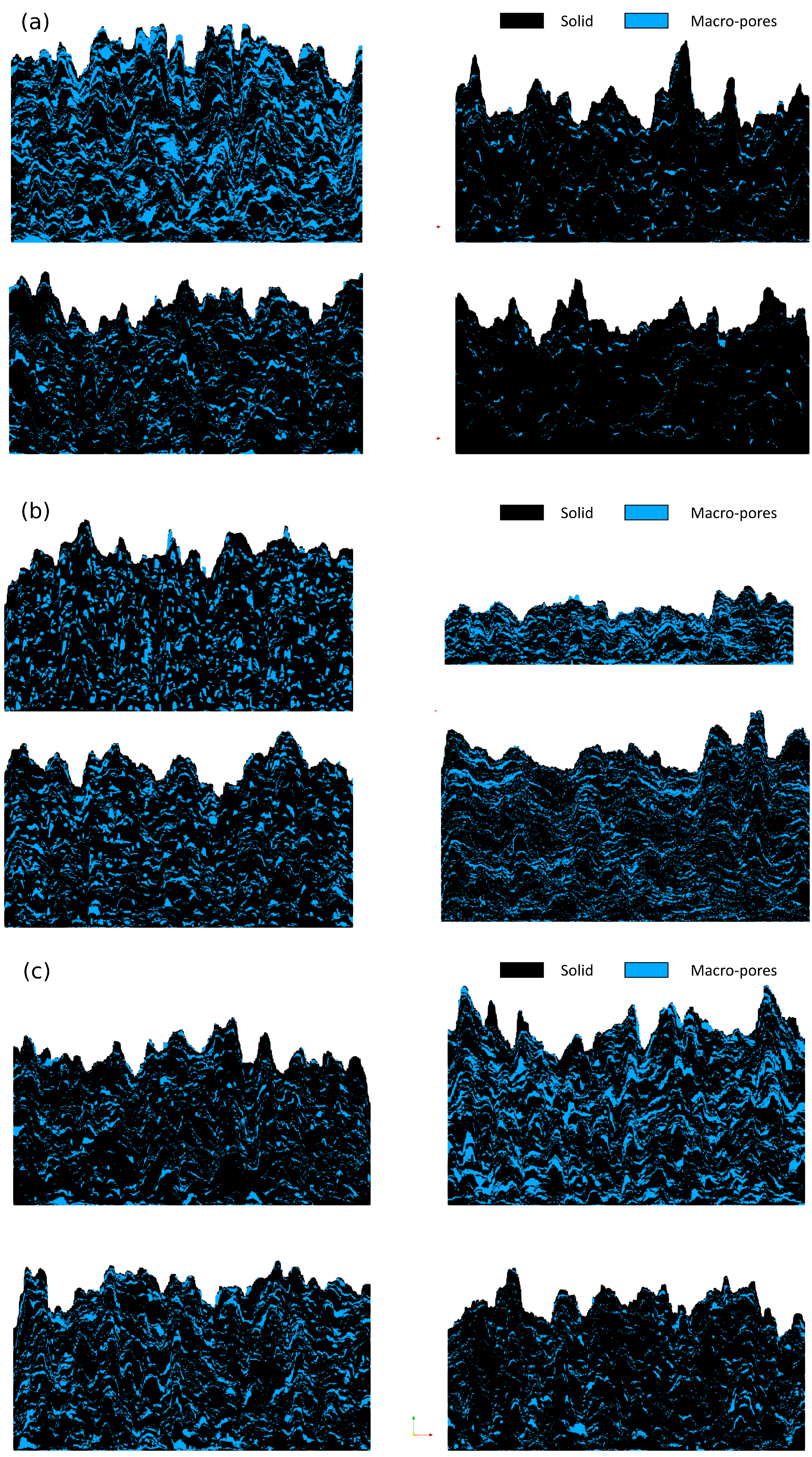
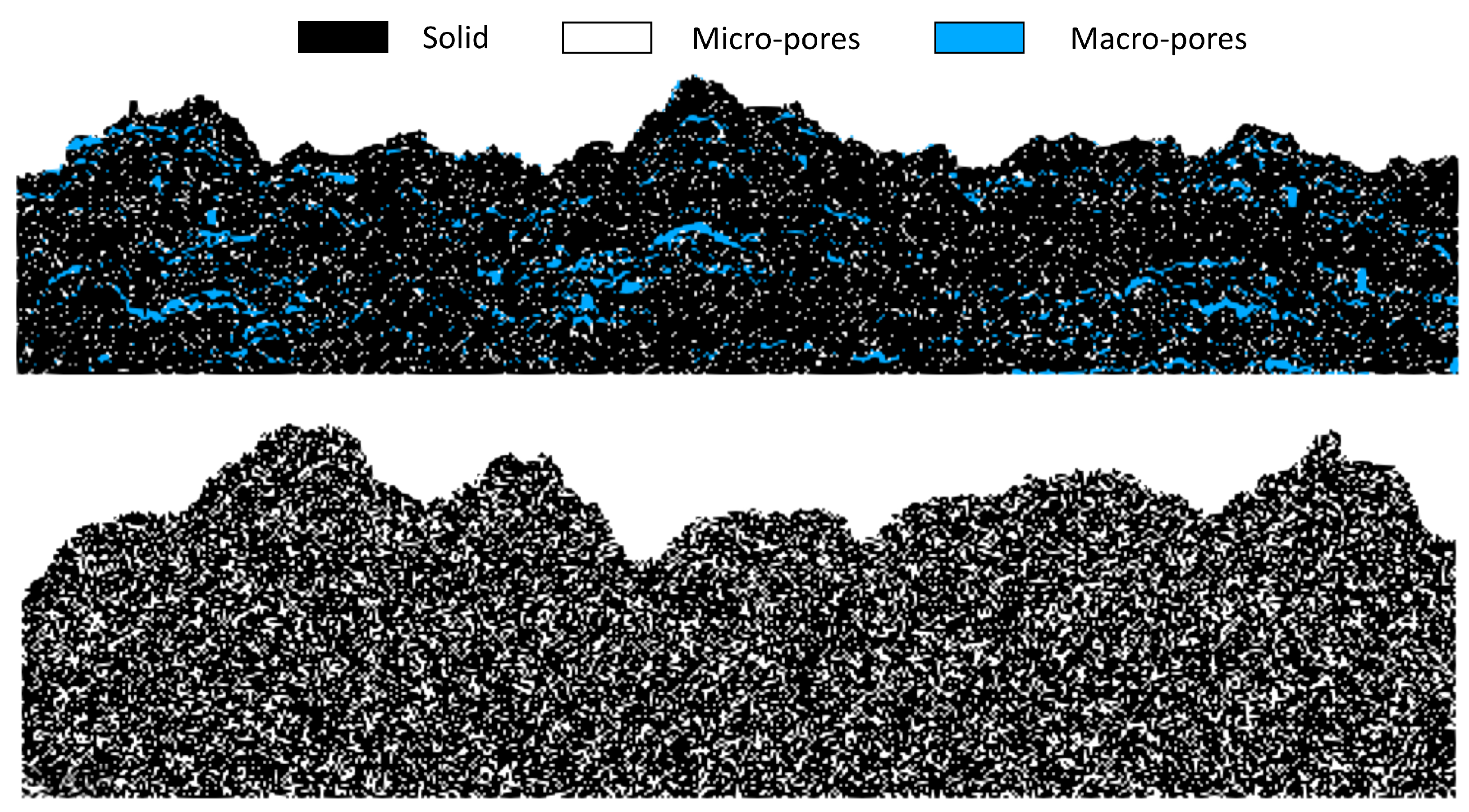
Another possibility offered by the proposed algorithm is the simplicity of mimicking alternative pore structures from macroscopic target variables such as overall porosity and the pore size distributions (Figure 1). This is achieved by assigning particle types, distinguishing between solid particles, voids belonging to macro-pore structures, or micro-pore structures (see Section 2.3.1 for detailed information). By incorporating this feature, the model not only preserves total porosity but also inherently maintains the pore size distribution. It is essential to emphasize that this approach is not intended to replace the ballistic deposition model, where pore structures emerge due to stickiness probability sampling. Instead, we propose extending the random deposition model by incorporating additional target variables (porosity and pore size distribution) and relying on statistical sampling to generate pores with precise spatial distributions. This simple addition unlocks the potential to simulate complex structures for transport phenomena, such as heat conduction and mass transfer, with desired parametric properties.
Figure 10 illustrates various examples of pore structures with different aspect ratios and pore size distributions, incurring minimal additional computational burden. Through the sampling of the cluster event type and its parameters, the same algorithm can create 3D structures with distinct global porosity (Figure 10a), pore shapes and aspect ratios (Figure 10b), and pore size distributions (Figure 10c). The introduction of porous structures can be further extended with a nucleation event (i.e., inner loop in Figure 2), where the dropped particle type can be sampled from a pre-defined distribution (Figure 11)). This capability enables the generation of micro-pores alongside the macro-pores introduced by selecting the type of clustering event (i.e., macro-pores). It should be remembered that the same idea can be utilized for any “particle type”, so that complex structures with multiple solids with different properties can be generated without any significant change in the model algorithm. Supplementary Material S1 includes two example codes illustrating the use of macro–micro pore particles within the proposed algorithm (Figure 2).
3.3. Proof-of-Concept: Urea Deposit Formation
While the proposed model exhibits the capability to generate deposit structures with varying macroscopic properties, such as surface roughness or characteristics of the Power Spectral Density (PSD) curve, the added value of this top-down approach requires further demonstration. To address this, we selected a problem that inspired this work—the urea deposit formation problem encountered in SCR systems due to complex heat and reactive mass transfer mechanisms [1]. Our previous measurements uncovered a unique scaling behavior for surface morphology under practically relevant conditions [1], a finding later confirmed in controlled single droplet experiments [43]. Additionally, we demonstrated that changes in deposit morphology significantly affect the re-atomization performance over static mixers, a crucial step in managing emissions in SCR systems [44]. Therefore, the representation of surface morphology for modeling other physical phenomena holds significant practical value.
The surface characterization of urea deposits revealed a mean Root Mean Square (RMS) of 50 μm with a standard deviation of 26 μm and an averaged slope of . When these target variables are represented in parallel coordinates, the model parameters were determined to be (Figure 12). Herein, the selection of the model parameters via parallel coordinates can be interpreted as a “coarse regression task”. In the subsequent step, the proposed algorithm is executed with these parameters 400 times to investigate the creativity and statistical consistency of the proposed approach. Figure 13a,b displays RMS variations along the width of the generated sample with 1 μm resolution over a substrate of 1000 × 1000, along with the Power Spectral Density (PSD) curves for 25 randomly selected surfaces, respectively. Overall, the 3D RMS values (interface width values for the entire surface) oscillate typically between 30–80 μm (Figure 13c). The immediate conclusion drawn from this observation is that the developed algorithm is both generative and statistically consistent. Interestingly, our approach yields statistics very similar to experimental observations, where the RMS values oscillate around 50 μm with a standard deviation of 26 μm. This similarity is also reflected in the variations in the PSD slopes (Figure 13d). The model produces surfaces with the expected scaling behavior but also oscillates around the set point, as observed during the experiments. This agreement confirms the robustness of the model and its capability to capture urea-derived deposit dynamics from a morphological perspective.
It is important to emphasize that urea crystallization is a complex process influenced by numerous factors specific to each application. The design of experiments often aims to achieve diverse practical objectives. Therefore, it is crucial to delve deeper into the connection between model parameters and macroscopic growth conditions observed in experiments. By utilizing the UWS example, we can gain deeper insights into how to select appropriate model parameters tailored to specific applications.
The final shape and morphology of deposits formed during the crystallization of UWS are strongly influenced by the dynamics of mass and heat transfer during the preceding solvent evaporation phase. For instance, if evaporation is diffusion-limited, the evaporation flux is non-uniform along the liquid–gas interface, particularly near the three-phase contact line. This non-uniformity can lead to capillary flows that transport dissolved solids towards the contact line, resulting in the formation of characteristic ring-like deposits, a phenomenon known as the “coffee-ring” effect. Conversely, Marangoni flows induced by surface tension gradients along the liquid–gas interface can lead to more uniform deposit distributions, or even reverse the coffee-ring effect. In particular, solutal Marangoni flows, driven by composition gradients in the solution, influence mass transport during evaporation, impacting the distribution of supersaturated regions within the liquid. Changes in surface properties, on the other hand, such as alterations in the contact angle due to variations in surface finishing or coating, can lead shift the balance between these two characteristic mechanisms, and lead to the dominance of solutal Marangoni flows. At elevated contact angles, pronounced Marangoni flows result in the distribution of soluted urea along the liquid–gas interface. Under such conditions, the entire interface becomes saturated with urea, eliminating localized concentration increases observed in cases of good wettability. Under these circumstances, the crystallization process mirrors a swift solidification of the liquid–gas interface. Continuous nucleation outpaces the growth of existing crystals, hastening the formation of a solid surface.
When considering the proposed top-down modeling approach, the presented UWS deposition case provides further insights into how these model parameters can be connected with a real, macroscopic deposition event. For UWS, Marangoni flows have a strong impact on crystallization behavior, as they define how supersaturated regions are distributed within the liquid. The internal flow field depends on both substrate temperature and the contact angle, which in turn are reflected in the time scales and dynamics of crystallization. Overall, these factors lead to extremely nonlinear dependencies for individual nucleation events. This was the reason for constructing the parameterized model presented in this study, where global parameters such as nucleation number density and their locations can be defined separately from nucleation event properties such as volume, spread dynamics, and diffusion. Depending on the experimental configuration (single droplet or a spray experiment, well-defined substrate temperature or a variable temperature field, contact angle, chamber temperature, whether there is already formed deposit on the surface or not), key mass transfer mechanisms can be identified a priori, and model parameters can be selected accordingly. Herein, the physical processes that lead to nucleation events should be aligned with the design philosophy of the model parameters. If the time scales of the deposition events are expected to be similar, then using group C behavior would be inappropriate. If the three-phase contact line of the spray is known, nucleation events should only be triggered in that particular spatial region. Another important point here is how asymmetrically the deposition process evolves for a given problem. For instance, during the crystallization of UWS sessile droplets, PSD signals, which is one of the key target variable to determine model parameters, exhibits three different behaviors following the trends in the crystallization dynamics and time scales [43]. In particular, capillary flow-dominated crystallization process (low contact angle) is vividly identified as a bimodal distribution of aggregate sizes across a deposit sample, with the number of smaller structures exhibiting much higher density. With the increased influence of Marangoni flow, the local size distributions of the deposits are much more uniform compared to the case where capillary flow dominates. Such a behaviour should be represented with nucleation type A. In our previous work with urea deposits, we also showed that this distinction also seems to be reflected onto the fractal dimension of the deposit surfaces [43]. In the same work, we also demonstrated that the effect of Marangoni flow becomes even more apparent (the higher the evaporation rates, the stronger the supersaturation of the liquid-gas interface) as the substrate temperature increases, leading to a more homogeneous appearance of the deposit surface.
As in all mathematical models, domain expertise would allow the user to select proper growth dynamics from the available options presented in Figure 3. We also suggest that the reader look into the provided deposition library and height profile images, together with the surface properties given in the parallel coordinates, to narrow down the model parameter search space for their particular application.
4. Conclusions
This paper introduces a robust deposition model, providing a versatile and generative framework for investigating the growth dynamics of deposits on surfaces in practical conditions. The study addresses crucial aspects related to deposition initiation, nucleation point behavior, spatial scaling, deposit growth rates, spread dynamics, and surface mobility. Adopting a top-down approach, the model utilizes a minimal set of parameters to generate diverse surface morphologies, effectively reverse engineering the sub-physics of the deposit formation process.
To establish a framework, 576 different parameter combinations were executed, generating a comprehensive dataset that connects model parameters with target variables, specifically surface roughness and deposit scaling characteristics obtained through Fast Fourier Transform. The impact of model parameters on surface morphology is elucidated through illustrative examples. Moreover, the robustness of the proposed algorithm is extended by integrating particle type concept, enabling the creation of porous structures with desired properties.
As a proof-of-concept, the paper further demonstrates the applicability of the top–down approach by employing the created dataset to select optimal model parameters for a specific problem. Results indicate that the model can generate surfaces with the desired properties, exhibiting similar variances compared to experimental measurements. Overall, the successful demonstration of the model’s applicability highlights its potential for understanding and predicting deposit growth in various real-world scenarios.
Supplementary Materials
The following supporting information can be downloaded at: https://0-www-mdpi-com.brum.beds.ac.uk/article/10.3390/dynamics4020014/s1, SM-S1: This package comprises code for generating both solid and porous deposits, accompanied by a README file for ease of use; SM-S2: The archive file encompasses a parallel coordinate HTML file along with the data and code essential for visualization; SM-S3: This archive provides detailed depictions of deposit morphologies under diverse settings, coupled with an analysis of their surface properties.
Author Contributions
Conceptualization, C.A. and R.K.; methodology, C.A.; software, C.A.; formal analysis, C.A.; writing—original draft preparation, C.A.; writing—review and editing, R.K. and H.-J.B.; visualization, C.A.; supervision, R.K. and H.-J.B.; project administration, C.A. and H.-J.B.; funding acquisition, C.A., R.K. and H.-J.B. All authors have read and agreed to the published version of the manuscript.
Funding
The authors would like to acknowledge Deutsche Forschungsgemeinschaft (DFG, German Research Foundation) for funding this work (Grant number AT 277/1-1).
Institutional Review Board Statement
Not applicable.
Informed Consent Statement
Not applicable.
Data Availability Statement
The code and the target library dataset can be found in Supplementary Materials S1 and S2, respectively. Supplementary Material S3 provides a visual library of the generated surfaces, as well as their quantitative properties.
Acknowledgments
We would like to thank Marion Börnhorst, KIT for the urea deposit experiments. We further thank Marcel Milich and Johannes Schneider from the Institute for Applied Materials, KIT for their assistance with microscopy measurements.
Conflicts of Interest
The authors declare no conflicts of interest. The funders had no role in the design of the study; in the collection, analyses, or interpretation of data; in the writing of the manuscript; or in the decision to publish the results.
Abbreviations
The following abbreviations are used in this manuscript:
| BD | Ballistic Deposition |
| FFT | Fast Fourier Transform |
| KPZ | Kardar–Parisi–Zhang |
| PSD | Power Spectral Density |
| RD | Random Deposition |
| RMS | Root Mean Square |
| SCR | Selective Catalytic Reduction |
| SF | Smoothing Factor |
| UWS | Urea Water Solution |
References
- Ates, C.; Börnhorst, M.; Koch, R.; Eck, M.; Deutschmann, O.; Bauer, H.J. Morphological characterization of urea derived deposits in SCR systems. Chem. Eng. J. 2021, 409, 128230. [Google Scholar] [CrossRef]
- Lehnen, C.; Lu, T.M. Morphological evolution in ballistic deposition. Phys. Rev. B—Condens. Matter Mater. Phys. 2010, 82, 085437. [Google Scholar] [CrossRef]
- Cagnetta, F.; Evans, M.R.; Marenduzzo, D. Kinetic roughening in active interfaces. EPJ Web. Conf. 2020, 230, 00001. [Google Scholar] [CrossRef]
- Krapivsky, P.L.; Redner, S. Birds on a wire. J. Stat. Mech. Theory Exp. 2022, 2022, 103405. [Google Scholar] [CrossRef]
- Giri, A.; Tarafdar, S.; Gouze, P.; Dutta, T. Fractal pore structure of sedimentary rocks: Simulation in 2-d using a relaxed bidisperse ballistic deposition model. J. Appl. Geophys. 2012, 87, 40–45. [Google Scholar] [CrossRef]
- Peng, C.K.; Buldyrev, S.; Goldberger, A.; Havlin, S.; Sciortino, F.; Simons, M.; Stanley, H. Fractal landscape analysis of DNA walks. Phys. A Stat. Mech. Its Appl. 1992, 191, 25–29. [Google Scholar] [CrossRef] [PubMed]
- Clay, M.P.; Simányi, N.J. Rényi’s parking problem revisited. Stochastics Dyn. 2016, 16, 1660006. [Google Scholar] [CrossRef]
- Vold, M.J. Computer simulation of floc formation in a colloidal suspension. J. Colloid Sci. 1963, 18, 684–695. [Google Scholar] [CrossRef]
- Meakin, P.; Ramanlal, P.; Sander, L.M.; Ball, R.C. Ballistic deposition on surfaces. Phys. Rev. A 1986, 34, 5091–5103. [Google Scholar] [CrossRef]
- Meakin, P. Ballistic deposition onto inclined surfaces. Phys. Rev. A 1988, 38, 994–1004. [Google Scholar] [CrossRef]
- Poxson, D.J.; Mont, F.W.; Schubert, M.F.; Kim, J.K.; Schubert, E.F. Quantification of porosity and deposition rate of nanoporous films grown by oblique-angle deposition. Appl. Phys. Lett. 2008, 93, 2981690. [Google Scholar] [CrossRef]
- Grüner, C.; Grüner, S.; Mayr, S.G.; Rauschenbach, B. Avoiding Anisotropies in On-Lattice Simulations of Ballistic Deposition. Phys. Status Solidi 2021, 258, 2000036. [Google Scholar] [CrossRef]
- Meakin, P.; Jullien, R. Spatially correlated ballistic deposition on one- and two-dimensional surfaces. Phys. Rev. A 1990, 41, 983–993. [Google Scholar] [CrossRef] [PubMed]
- Wolf, D.E.; Villain, J. Growth with Surface Diffusion. Europhys. Lett. 1990, 13, 389. [Google Scholar] [CrossRef]
- Meakin, P.; Jullien, R. Ballistic deposition with sticky and non-sticky particles. Phys. A Stat. Mech. Its Appl. 1991, 175, 211–221. [Google Scholar] [CrossRef]
- Ermak, D.L.; Buckholz, H. Numerical integration of the Langevin equation: Monte Carlo simulation. J. Comput. Phys. 1980, 35, 169–182. [Google Scholar] [CrossRef]
- El-Nashar, H.F.; Wang, W.; Cerdeira, H.A. Ballistic deposition model for multiple species with next nearest-neighbour interactions in (2 + 1)-dimensions. Surf. Sci. 1997, 391, 1–10. [Google Scholar] [CrossRef]
- Wang, W.; Cerdeira, H.A. Surface growth of two kinds of particle deposition models. Phys. Rev. E 1995, 52, 6308–6313. [Google Scholar] [CrossRef] [PubMed]
- Pellegrini, Y.P.; Jullien, R. Roughening transition and percolation in random ballistic deposition. Phys. Rev. Lett. 1990, 64, 1745–1748. [Google Scholar] [CrossRef]
- El-Nashar, H.F.; Cerdeira, H.A. Dynamic scaling in a ballistic deposition model for a binary system. Phys. Rev. E Stat. Phys. Plasmas Fluids Relat. Interdiscip. Top. 2000, 61, 6149–6155. [Google Scholar] [CrossRef]
- Horowitz, C.M.; Monetti, R.A.; Albano, E.V. Competitive growth model involving random deposition and random deposition with surface relaxation. Phys. Rev. E Stat. Nonlinear Soft Matter Phys. 2001, 63, 066132. [Google Scholar] [CrossRef] [PubMed]
- Das, S.K.; Banerjee, D.; Roy, J.N. Stochastic Study of Random-Ballistic Competitive Growth Model in 2+1 Dimension and Related Scaling Exponents. J. Inst. Eng. Ser. D 2023, 104, 777–784. [Google Scholar] [CrossRef]
- Karmakar, R.; Dutta, T.; Lebovka, N.; Tarafdar, S. Effect of surface roughness on the bulk properties of simulated porous media. Phys. A: Stat. Mech. Its Appl. 2005, 348, 236–244. [Google Scholar] [CrossRef]
- Forgerini, F.L.; Figueiredo, W. Random deposition of particles of different sizes. Phys. Rev. E Stat. Nonlinear Soft Matter Phys. 2009, 79, 041602. [Google Scholar] [CrossRef] [PubMed]
- Ebrahiminejad, Z.; Masoudi, S.F.; Dariani, R.S.; Jahromi, S.S. Thin film growth by deposition of randomly shaped clusters. J. Chem. Phys. 2012, 137, 4755956. [Google Scholar] [CrossRef] [PubMed]
- Sharafedini, E.; Hamzehpour, H.; Masoudi, S.F.; Sahimi, M. Electrical conductivity of the films grown by ballistic deposition of rodlike particles. J. Appl. Phys. 2015, 118, 4936548. [Google Scholar] [CrossRef]
- Madadi, Z.; Hassanibesheli, F.; Esmaeili, S.; Hedayatifar, L.; Masoudi, A.A. Surface growth by cluster particles: Effects of diffusion and cluster’s shape. J. Cryst. Growth 2017, 480, 56–61. [Google Scholar] [CrossRef]
- Hosseinabadi, S.; Masoudi, A.A. Random deposition with a power-law noise model: Multiaffine analysis. Phys. Rev. E 2019, 99, 012130. [Google Scholar] [CrossRef]
- Das, S.K.; Banerjee, D.; Roy, J.N. Particle shape-induced correlation effect in random deposition in 1 + 1 dimension and related effect in ballistic deposition. Surf. Rev. Lett. 2021, 28, 2050043. [Google Scholar] [CrossRef]
- Comets, F.; Dalmau, J.; Saglietti, S. Scaling limit of the heavy tailed ballistic deposition model with p-sticking. Ann. Probab. 2023, 51, 1870–1931. [Google Scholar] [CrossRef]
- Rahimi, M.; Hosseinabadi, S.; Masoudi, A. Geometrical exponents of contour loops on ballistic deposition model with power-law distributed noise. Chaos Solitons Fractals 2023, 177, 114249. [Google Scholar] [CrossRef]
- Hu, G.; Orkoulas, G.; Christofides, P.D. Regulation of film thickness, surface roughness and porosity in thin film growth using deposition rate. Chem. Eng. Sci. 2009, 64, 3903–3913. [Google Scholar] [CrossRef]
- Robledo, A.; Grabill, C.N.; Kuebler, S.M.; Dutta, A.; Heinrich, H.; Bhattacharya, A. Morphologies from slippery ballistic deposition model: A bottom-up approach for nanofabrication. Phys. Rev. E Stat. Nonlinear Soft Matter Phys. 2011, 83, 1–9. [Google Scholar] [CrossRef] [PubMed]
- Banerjee, K.; Shamanna, J.; Ray, S. Surface morphology of a modified ballistic deposition model. Phys. Rev. E Stat. Nonlinear Soft Matter Phys. 2014, 90, 3–9. [Google Scholar] [CrossRef] [PubMed]
- Aarão Reis, F.D. Kinetic roughening and porosity scaling in film growth with subsurface lateral aggregation. Phys. Rev. E Stat. Nonlinear Soft Matter Phys. 2015, 91, 1–9. [Google Scholar] [CrossRef]
- Mal, B.; Ray, S.; Shamanna, J. Surface properties and scaling behavior of a generalized ballistic deposition model. Phys. Rev. E 2016, 93, 3–8. [Google Scholar] [CrossRef] [PubMed]
- Kartha, M.J. Surface morphology of ballistic deposition with patchy particles and visibility graph. Phys. Lett. A 2017, 381, 556–560. [Google Scholar] [CrossRef]
- Oliveira Filho, J.S.; Oliveira, T.J.; Redinz, J.A. Surface and bulk properties of ballistic deposition models with bond breaking. Phys. A Stat. Mech. Its Appl. 2013, 392, 2479–2486. [Google Scholar] [CrossRef]
- Nasehnejad, M.; Nabiyouni, G.; Gholipour Shahraki, M. Thin film growth by 3D multi-particle diffusion limited aggregation model: Anomalous roughening and fractal analysis. Phys. A Stat. Mech. Its Appl. 2018, 493, 135–147. [Google Scholar] [CrossRef]
- Corwin, I. The Kardar-Parisi-Zhang Equation and Universality Class; World Scientific: Singapore, 2011. [Google Scholar]
- Takeuchi, K.A. An appetizer to modern developments on the Kardar–Parisi–Zhang universality class. Phys. A Stat. Mech. Its Appl. 2018, 504, 77–105. [Google Scholar] [CrossRef]
- Corwin, I. Kardar-Parisi-Zhang Universality. Not. AMS 2016, 63, 230–239. [Google Scholar] [CrossRef]
- Schumacher, O.; Ates, C.; Börnhorst, M.; Koch, R.; Stephan, P. Deposit formation from evaporating urea-water droplets on substrates of different wettability. J. Colloid Interface Sci. 2023, 634, 21. [Google Scholar] [CrossRef] [PubMed]
- Dörnhöfer, J.; Börnhorst, M.; Ates, C.; Samkhaniani, N.; Pfeil, J.; Wörner, M.; Koch, R.; Bauer, H.J.; Deutschmann, O.; Frohnapfel, B.; et al. A Holistic View on Urea Injection for NOx Emission Control: Impingement, Re-atomization, and Deposit Formation. Emiss. Control. Sci. Technol. 2020, 6, 228–243. [Google Scholar] [CrossRef]
Figure 1.
Proposed top-down approach to create surfaces with different target properties.

Figure 2.
Algorithm of the proposed deposit formation model.

Figure 3.
Details of the model parameters to change the deposit morphology at macroscopic (a) and microscopic (b) scale. Formation of deposit clusters for a set of parameters including surface diffusion is also depicted (c).
Figure 3.
Details of the model parameters to change the deposit morphology at macroscopic (a) and microscopic (b) scale. Formation of deposit clusters for a set of parameters including surface diffusion is also depicted (c).

Figure 4.
Visualization of the target library with the model feature space via parallel coordinates. The RMS axis is ranged up to 150 μm for better visibility. The data, interactive html file and plotting script can be found in Supplementary Material S2 to generate alternative views.
Figure 4.
Visualization of the target library with the model feature space via parallel coordinates. The RMS axis is ranged up to 150 μm for better visibility. The data, interactive html file and plotting script can be found in Supplementary Material S2 to generate alternative views.

Figure 5.
Microscopic view of urea deposits at different magnifications.

Figure 6.
Impact of cluster type on the generated deposit height profiles with 1 μm resolution over a substrate of 1000 × 1000 units. The remaining parameters are given at the top of each figure groups. The legends show the height profile. The remaining surface profiles for other parameter combinations can be found in Supplementary Material S3.

Figure 7.
Impact of cluster type on the surface roughness with 1 μm resolution over a substrate of 1000 × 1000 units. X axis gives the calculated RMS for each 2D cut-plane over the 3D deposit topology. Each curve represents a different smoothing factor (SF). The remaining parameters are given at the top of each figure groups. The remaining profiles for other parameter combinations can be found in Supplementary Material S3.

Figure 8.
Impact of cluster type on the PSD curves with 1 μm resolution over a substrate of 1000 × 1000 units. Each curve represents a different smoothing factor (SF). The remaining parameters are given at the top of each figure groups. The remaining profiles for other parameter combinations can be found in Supplementary Material S3.

Figure 9.
Impact of surface diffusion on the generated deposit height profiles with 1 μm resolution over a substrate of 1000 × 1000 units. The remaining parameters are given at the top of each figure groups. The legends show the height profile. The remaining surface profiles for other parameter combinations can be found in Supplementary Material S3.

Figure 10.
Porous structures generated with the proposed algorithm with varying (a) global porosity, (b) pore cluster shape/aspect ratio and (c) pore size distributions.
Figure 10.
Porous structures generated with the proposed algorithm with varying (a) global porosity, (b) pore cluster shape/aspect ratio and (c) pore size distributions.

Figure 11.
Porous structures generated with the proposed algorithm with macro and micro pore types. Macro-pores are sampled as nucleation events, while micro-pores are generated by sampling the particle type during a RD event for a given nucleus. An example of the pore sampling procedure can be found in Supplementary Material S1.

Figure 12.
Identification of model parameters with the measured RMS and PSD slope values. The interactive html file and plotting script can be found in Supplementary Material S2 to generate alternative views.
Figure 12.
Identification of model parameters with the measured RMS and PSD slope values. The interactive html file and plotting script can be found in Supplementary Material S2 to generate alternative views.

Figure 13.
Surface properties of the generated deposits with . (a) 2D RMS profiles along the y axis, (b) mean PSD curve for each deposit surface, (c) variations in 3D RMS of the deposits, (d) variations in the slopes of the PSD curves.
Figure 13.
Surface properties of the generated deposits with . (a) 2D RMS profiles along the y axis, (b) mean PSD curve for each deposit surface, (c) variations in 3D RMS of the deposits, (d) variations in the slopes of the PSD curves.

Disclaimer/Publisher’s Note: The statements, opinions and data contained in all publications are solely those of the individual author(s) and contributor(s) and not of MDPI and/or the editor(s). MDPI and/or the editor(s) disclaim responsibility for any injury to people or property resulting from any ideas, methods, instructions or products referred to in the content. |
© 2024 by the authors. Licensee MDPI, Basel, Switzerland. This article is an open access article distributed under the terms and conditions of the Creative Commons Attribution (CC BY) license (https://creativecommons.org/licenses/by/4.0/).
Share and Cite
MDPI and ACS Style
Ates, C.; Koch, R.; Bauer, H.-J. A Versatile Deposition Model for Natural and Processed Surfaces. Dynamics 2024, 4, 233-253. https://0-doi-org.brum.beds.ac.uk/10.3390/dynamics4020014
AMA Style
Ates C, Koch R, Bauer H-J. A Versatile Deposition Model for Natural and Processed Surfaces. Dynamics. 2024; 4(2):233-253. https://0-doi-org.brum.beds.ac.uk/10.3390/dynamics4020014
Chicago/Turabian StyleAtes, Cihan, Rainer Koch, and Hans-Jörg Bauer. 2024. "A Versatile Deposition Model for Natural and Processed Surfaces" Dynamics 4, no. 2: 233-253. https://0-doi-org.brum.beds.ac.uk/10.3390/dynamics4020014