Optimization of a New Design of Molten Salt-to-CO2 Heat Exchanger Using Exergy Destruction Minimization


1
E.T.S. Ingenieros Industriales-UNED, C/Juan del Rosal 12, 28040 Madrid, Spain
2
Rafael Mariño Chair in New Energy Technologies–COMILLAS-ICAI, C/Alberto Aguilera 25, 28015 Madrid, Spain
*
Author to whom correspondence should be addressed.
Entropy 2020, 22(8), 883; https://0-doi-org.brum.beds.ac.uk/10.3390/e22080883
Submission received: 16 July 2020
/
Revised: 31 July 2020
/
Accepted: 8 August 2020
/
Published: 12 August 2020
(This article belongs to the Special Issue Thermodynamic Optimization of Complex Energy Systems)
Abstract
:One of the ways to make cost-competitive electricity, from concentrated solar thermal energy, is increasing the thermoelectric conversion efficiency. To achieve this objective, the most promising scheme is a molten salt central receiver, coupled to a supercritical carbon dioxide cycle. A key element to be developed in this scheme is the molten salt-to-CO2 heat exchanger. This paper presents a heat exchanger design that avoids the molten salt plugging and the mechanical stress due to the high pressure of the CO2, while improving the heat transfer of the supercritical phase, due to its compactness with a high heat transfer area. This design is based on a honeycomb-like configuration, in which a thermal unit consists of a circular channel for the molten salt surrounded by six smaller trapezoidal ducts for the CO2. Further, an optimization based on the exergy destruction minimization has been accomplished, obtained the best working conditions of this heat exchanger: a temperature approach of 50 °C between both streams and a CO2 pressure drop of 2.7 bar.
1. Introduction
The main advantages of the energy supplied through Solar Thermal Power Plants (STPPs) are its capacity, reliability and stability to the grid, which in turn allows the renewable electricity percentage to be also higher. However, when compared to the costs of solar photovoltaic electricity, the reduction in cost must still be very large for solar thermal electricity, to be competitive. One of the ways to achieve this is by increasing global conversion efficiency by coupling the solar field to a supercritical cycle. In this scheme, a reliable design of the heat exchanger between the solar field and the Brayton cycle is essential for the technical viability of these STPPs.
Within the SunShot program [1], the U.S. Department of Energy (DOE) has identified three potential schemes for the next generation of STPPs, based on the Heat Transfer Fluid (HTF) in the receiver: molten salts, falling particles or gas phase. In all the schemes, the solar field is coupled to a supercritical carbon dioxide (sCO2) cycle, achieving high thermo-electric conversion efficiency.
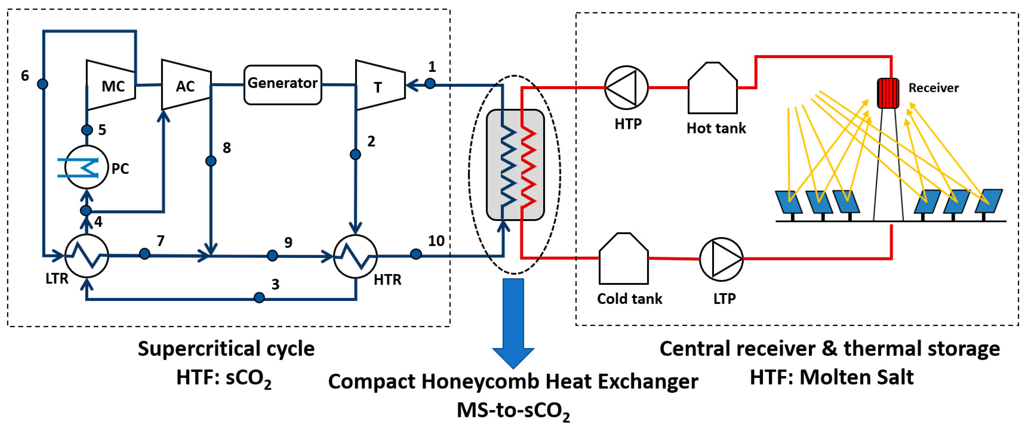
The scheme based on a molten salt central receiver coupled to a sCO2 Brayton cycle is the most conventional one, as the molten salt systems are a state-of-art technology. Besides that, the Thermal Energy Storage (TES) associated, provides this scheme of a high capacity factor and a dispatchable electricity production [2]. This scheme is showed in Figure 1.
Nevertheless, several challenges arise in this technology, like an efficient central receiver working at a temperature higher than 700 °C; a supercritical cycle that maximizes performance and minimizes cost, taking into account the peculiarities of the solar field to which it is coupled; and, between these two subsystems, a key element is the heat exchanger (HX) to transfer energy from the molten salt in the solar field to the CO2 in the Brayton cycle, the Source Heat Exchanger (SHX). This paper deals in depth with this last equipment, proposing a design that can overcome some of the technological difficulties of these type of HXs: the mechanical stress due to the high pressure of the supercritical phase; the need of improving the heat transfer of the supercritical fluid; and overall, the molten salt plugging in the microchannels of a Compact Heat Exchanger (CHX), as it will be explained below.
Supercritical CO2 Brayton cycles have a very high efficiency, above 50%, even with dry-cooling [3], so their integration in a STPP can yield to an overall performance increase. Wang et al. [4] identified six possible supercritical cycles that can be integrated in a molten salt central receiver system with thermal storage: simple recovery cycle; recompression cycle; precompression cycle; intercooling cycle; partial-cooling cycle; and split expansion cycle. These cycles can be assessed according to different parameters, being the most important ones: the cycle efficiency; the complexity of the cycle compared to the most conventional one, the recompression cycle (represented in Figure 1); and the CO2 temperature increment in the source heat exchanger, as this value determines the molten salt volume in the solar field.
The intercooling cycle is the one with higher thermal efficiency when the thermal source temperature ranges from 600 °C to 800 °C, followed by the recompression cycle, that is also the simplest. Regarding the temperature difference in the source heat exchanger, the partial cooling layout is the one with the largest increment. In summary, three cycles can be identified to be the most suitable for coupling to a molten salt central receiver: recompression cycle, intercooling cycle and partial-cooling cycle [4,5]
The central receiver is usually a external-type with a surrounding heliostat field [1], although the cavity-type is recommended in recent investigations when the working temperature is high [2], because the radiation heat loss is lower compared to external receivers working at the same temperature. At last, the molten salt thermal storage consists of two tanks of molten salts, which have been sized to provide the nominal thermal power to the supercritical cycle for 6 h, with a charging time of 6 h.
This paper is focused in the heat exchanger between the solar field and the supercritical cycle, so a literature review on this heat exchanger is presented below.
There are several designs proposed in the literature for MS-to-CO2 heat exchangers, for both nuclear and solar applications, since both technologies use the scheme of a thermal source coupled to a supercritical CO2 cycle, as an alternative to increase performance.
The simplest design for this heat exchanger is a Shell and Tube Heat Exchanger (STHX), in which the CO2 at supercritical pressure circulates inside the tubes, and the molten salt trough the shell. This HX is well suited in supercritical cycles in which the source thermal energy is supplied through the low pressure side of the layout (85 bar approximately), as the one presented in [6]. Nevertheless, if a conventional supercritical cycle is used, the turbine inlet pressure should be limited to 200 bar, which constrains the cycle efficiency. There are several reasons that make the STHX not the most appropriate in conventional supercritical cycles: the great tube thickness due to the high pressure of the CO2 yields to a limited heat transfer and performance [7]; and, although the molten salt plugging does not occur in the shell, this fluid can be kept retained in the baffles and interstices of the HX, also yielding to a reduction in the heat transfer [8,9].
A more advanced design is the Printed Circuit Heat Exchanger (PCHE), which consists of plate sheets joined by diffusion-bonding, alternating hot-cold rows of semi-circular channels [10,11]. These microchannels withstand the high pressure of the CO2 (180–300 bar, approximately), and they also improve the heat transfer of this fluid, as the convection coefficient and the hydraulic diameter are inversely related. Nevertheless, PCHEs have the drawback of the viscous molten salt plugging in the microchannels. This issue has been studied in several reports of both nuclear [12] and solar [13] power plants, but very few designs address this problem. The most recent designs of MS-to-CO2 based on PCHE are focused on the heat transfer improvement by using airfoil fins in the microchannels [14,15,16].
Only one design has been found in the bibliography that tries to solve the problem of the molten salt plugging in microchannels [17]; the basic principle of this design is to face two plate sheets intended for molten salt, so that a circular channel is formed for this fluid, whereas the CO2 still circulates through semi-circular channels. Although this design does not optimize the heat transfer, the plugging and corrosion problems of the MS are reduced; nevertheless, the channel dimension for the molten salt is still small.
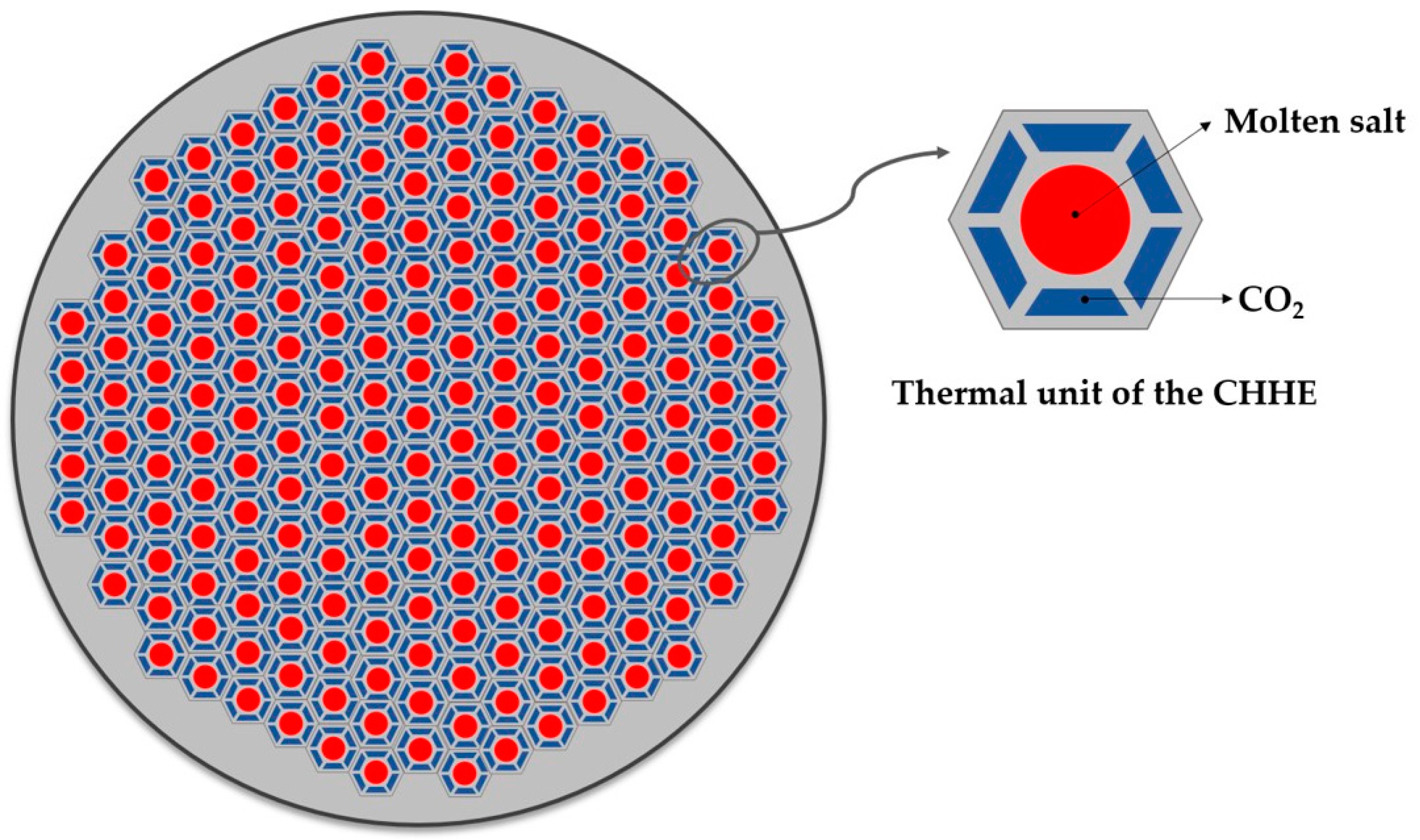
To overcome the problems detailed in the two HX configurations described above, this work proposes and studies a new MS-to-CO2 HX design. From the analysis of the state of the art, it is clear that it would be desirable to increase the ratio of heat transfer area compared to the volume of the HX, that is, the most suitable design is a Compact Heat Exchanger (CHX); the lower convection coefficient of the supercritical phase is compensated by the larger area to transfer the thermal energy. But, at the same time, the MS channel must be larger enough to avoid plugging. To meet both conditions, a small compact shell and tube design [18] has been modified for the thermal duty and working pressure required by the supercritical cycle. The cross section of this design is a compact shell consisting of many thermal units like the one shown in Figure 2. The MS goes through a circular duct that is surrounded by 6 trapezoidal ducts, through which the CO2 circulates. Repetition of this unit gives the cross section of the shell a honeycomb-like appearance. Because of that, this HX will be referred as Compact Honeycomb Heat Exchanger (CHHE).
2. Thermal Model and Boundary Conditions of the Compact Honeycomb Heat Exchanger
2.1. Thermal Inputs and Boundary Conditions from the Supercritical Cycle and the Solar Field
The CHHE is located between the supercritical cycle and the solar field as shown in Figure 1. The supercritical cycle is a conventional recompression cycle that is one of the three layouts (with the partial cooling and the intercooling) that show better characteristics to be coupled to a molten salt solar tower plant [4,5]. The cycle power output is 50 MWe, for which, the thermal energy in the CHHE is 100.99 MWth. Table 1 shows the thermodynamic properties of the state points following the numbering marked in Figure 1.
Figure 3 shows the temperature-entropy diagram of this supercritical cycle. As it can be seen, this cycle is characterized by two compressors (processes 5, 6 and 4–8) and two recuperators, for low and high temperature (LTR and HTR, respectively). The source heat exchanger is characterized by process 10–1.
2.2. Heat Transfer Fluids and Mechanical Design of the CHHE
As the CHHE is located between the supercritical Brayton cycle and the solar field, the thermal fluids of this heat exchanger are the CO2 (cold side) and the molten salt (hot side). The CO2 thermodynamic properties have been obtained from NIST database [19]. On the other hand, the molten salt selected as HTF in the solar field and, thus, in the CHHE is a ternary chloride salt MgCl2/NaCl/KCl. This salt has a low melting point (385 °C) and a high thermal decomposition temperature (>800 °C), yielding to a large working temperature range; it has the cheapest estimated cost; and its volumetric heat capacity is higher, so its volume for a given thermal storage size is lower. Table 2 summarizes the main thermal properties of the ternary chloride molten salt selected [2].
The alloy selected for the CHHE is Haynes 242 (65%Ni-8%Cr-25%Mo, % weight). This alloy shows a good corrosion resistance in MS at temperatures higher than 700 °C, due to the higher percentage of molybdenum [20]. Besides that, the maximum allowable stress at the design temperature is very high, so it can withstand the high pressure difference at the working conditions [21]. The minimum thickness between the CO2 and the MS is calculated applying ASME codes [22].
The thermal power required in the source heat exchanger is 100.99 MWth, as pointed above. The CHHE has been divided in three modules of 33.66 MWth. The inlet temperatures of both the MS and the CO2 are also fixed by the solar field and the supercritical cycle, respectively. The CHHE is considered to be a balanced counter-flow heat exchanger.
There are two thermal inputs that will be parametrized for the optimization procedure in next section: the temperature approach (TAMS-CO2) between both streams, considering a balanced HX, and the pressure drop of the supercritical phase (dPCO2), which is the main pressure drop; once the CO2 pressure drop is fixed, the heat exchanger length is also fixed, and thus the MS pressure drop.
For a particular value of each of the previous two parameters (TAMS-CO2 and dPCO2), the outlet temperatures and the velocities of both streams are fixed. In this way, all the thermophysical properties that define the heat exchanger are established.
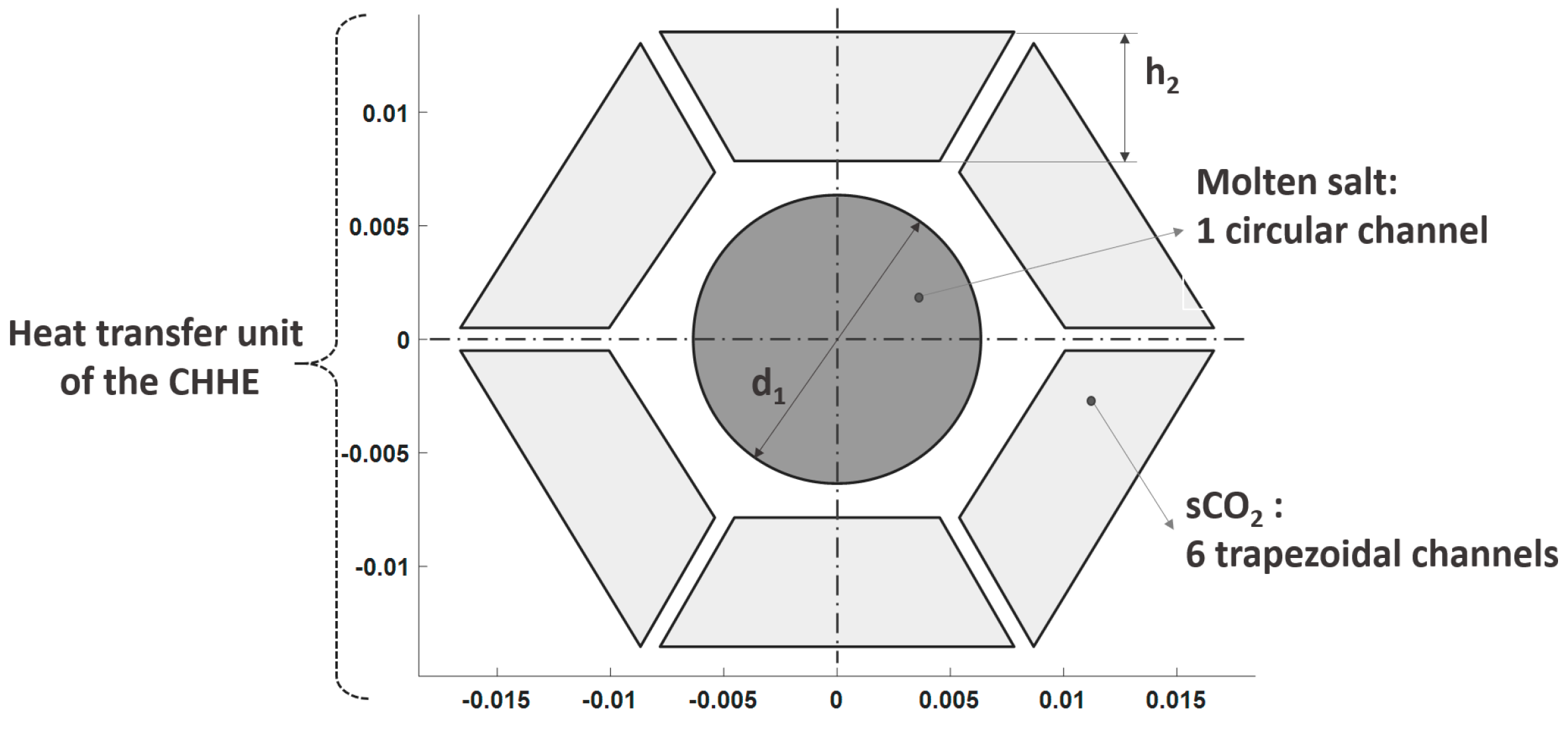
Figure 4 represents a thermal unit of the CHHE accounting for the dimensions. Regarding the geometric parameters of the heat transfer unit, the MS channel diameter (d1 in Figure 4) has been set to 0.5 inch (12.7 mm), whereas the CO2 trapezoidal channel width (h2 in Figure 4) has been set to 5.7 mm. The trapezoidal shape of the duct cross section has been chosen because of geometric reasons, since in this way it is easy to form a thermal unit with a hexagonal shape whose repetition allows creating a honeycomb-like structure. The MS channel diameter is the minimum value reported in [23], that ensures the salt flow without clogging; and the CO2 channel dimensions have been selected to avoid a great pressure drop without penalizing the heat transfer due to a lower CO2 velocity. The pressure drop in the source heat exchanger of a STPP ranges from 2 to 3 bar, depending on the daily operation hours; this a greater value than that of baseload plants [24], that can operate continuously.
2.3. Thermo-Fluid Dynamic Model of the CHHE
Once geometric and thermal parameters are defined, the CHHE is calculated by a two dimensional thermo-fluid dynamic model. The heat exchanger is divided in N heat exchanger elements (HXEs), along the longitudinal direction, of the same thermal duty: . In every element, the thermophysical properties of both fluids are assumed constant and equal to the average between the inlet and the outlet.
The overall heat transfer coefficient of the counterflow elementary CHHE, , is calculated by Equation (1).
is the thermal transfer coefficient for the wall between channels, that accounts for an equivalent constant thickness [25]; and hconv (W/m2/°C) is the convection heat transfer coefficient.
In this particular case, the flow, for both MS and CO2, is fully-developed turbulent (Re > 2300), so Gnielinski correlation is recommended [18], given by Equation (2).
This correlation is valid for Reynolds numbers ranging from 2300 to 5 × 10⁵ and Prandtl numbers from 0.5 to 2000. In the above equation fc is the friction factor, calculated as needed from the Filonenko correlation [26]; ReDh is the Reynolds number based on the inner hydraulic diameter; Pr is Prandtl number at the bulk fluid temperature; Prsi is the Prandtl number at the inner duct temperature, tsi.
In case of laminar flow (only for molten salt under particular conditions), the Nusselt number is constant, as seen in Equation (3).
Once the value of the global heat transfer coefficient is known, length of every HXE is calculated by means of the basic equation of heat transfer, Equation (4).
is the thermal duty of every HXE; is the heat transfer area of every HXE; (°C) is the mean temperature, that is constant, as the CHHE is balanced and the CO2 is considered as an ideal gas. The length of every HXE, , is calculated from the heat transfer area, .
Finally, friction pressure destruction is calculated by means of the Darcy-Weisbach equation [18], for both fluids:
where Dh (m) is the hydraulic diameter of the duct; ρ (kg/m3) is the average fluid density; u (m/s) is the average fluid velocity; and fD is the Darcy friction factor, that is calculated by the Techo et al. correlation [18], for turbulent flow (); or the Hägen-Poiseulle correlation [18], in case of laminar flow (); finally, the subindex i refers to the each fluid: molten salt or CO2.
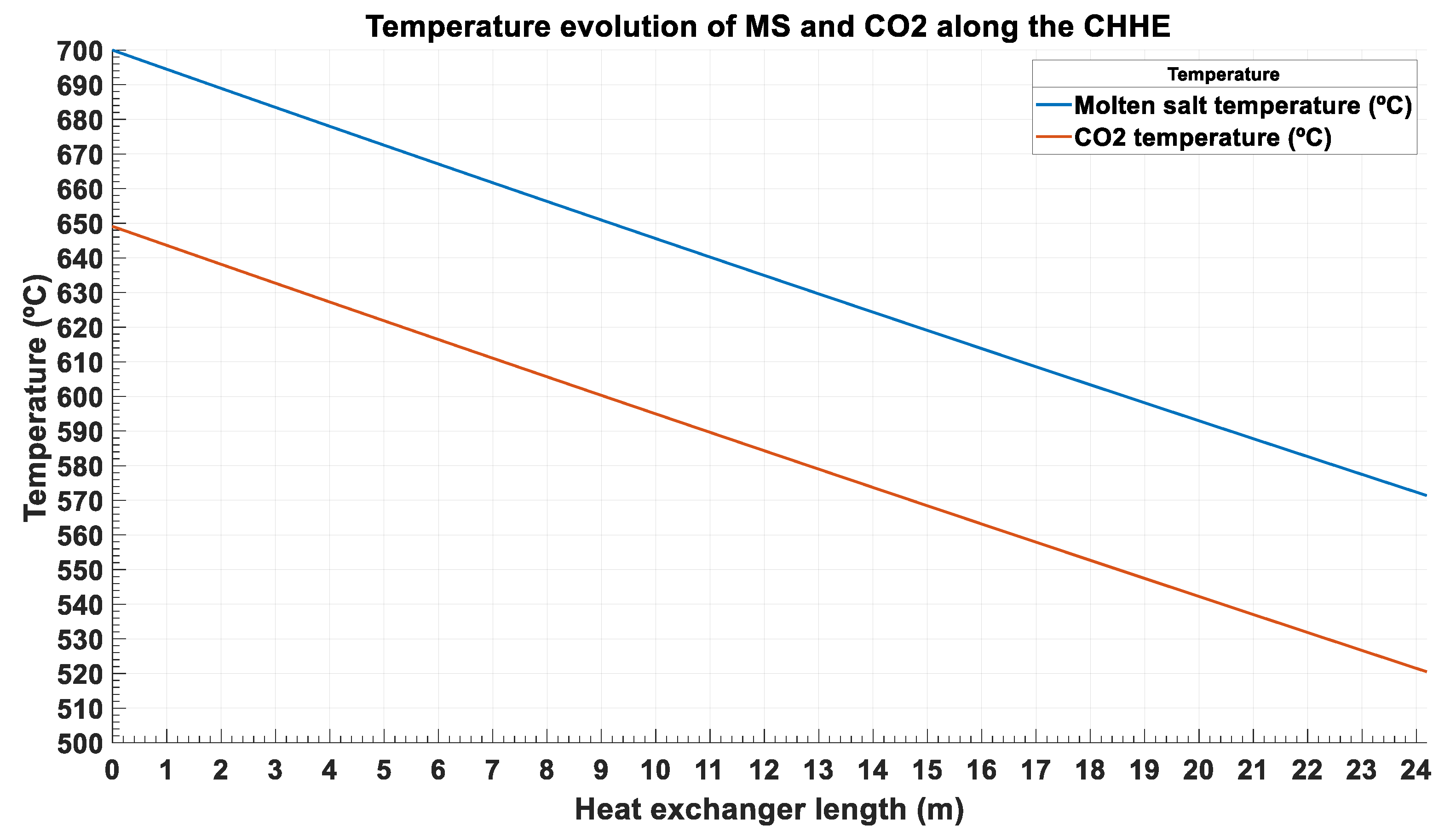
Figure 5 shows the temperature evolution of the MS and the CO2 for a CHHE with a temperature approach TAMS-CO2 = 52 °C and a pressure drop dPCO2 = 2.75 bar. As it will be explained in next section, these values minimize the exergy destruction for the CHHE proposed.
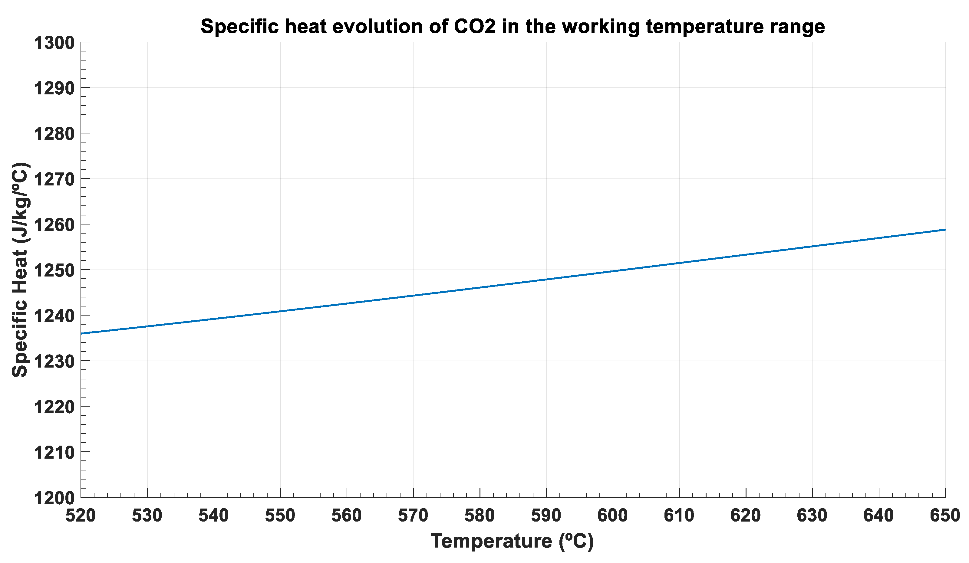
From Figure 5, it is concluded that temperature evolution is almost lineal for both streams, which means that specific heat is nearly constant. This is clear for the molten salt, which is an incompressible fluid approximately, but also for the supercritical CO2, as this fluid is at very high temperature and far away from the critical point. Figure 6 shows that specific heat ranges from 1.236 kJ/kg/°C to 1.258 kJ/kg/°C in the working temperature values (from 520 °C to 650 °C).
The main thermal and geometric parameters of this optimal CHHE are shown in Table 3. As seen in this table, this CHHE is divided into 6 smaller modules: 3 modules in parallel, in order not to have a shell diameter greater than 1 m; and 2 modules in series, for not exceeding 15 m long. As this HX is a new and not built design, it is difficult to set manufacturing restrictions, so these maximum values have been set according to the STHX limitation, in which the ratio shell diameter to length must be greater than 1/15.
The thermal model presented in this section has not been validated with empirical results, as it is a new design of heat exchanger. Nevertheless, the correlations used in this model, for both the CO2 and the ternary chloride molten salt have been validated in other HX designs for the same performance, by means of a numerical model in CFD, as the one presented in [17].
3. Optimization Procedure of the Heat Exchanger Based on the Exergy Destruction Minimization
The optimization of the CHHE proposed is based on the minimization of the exergy destruction, or entropy generation, in the heat exchanger. Assigning monetary values to these irreversibilities, this method allows to assess the cost of exergy destruction on each stream of the heat exchanger against its capital cost. Thus, the new objective function to be minimized is the Annual Total Cost (ATC), which takes into account the investment cost and the operation cost, including the irreversibilities in this last one.
In Equation (6), CRF is the capital-recovery factor and CELF is the constant-escalation levelization factor, both defined below; CE is the cost per unit of exergy ($/Wh), which has been taken as 0.00005$/Wh, according to several references [27,28]; Y is the yearly operation time, calculated for a solar multiple equal to 2: Y = 365*12 h; CC is the investment cost of the CHHE; finally, is the total exergy destruction due to the most important irreversibilities in the heat exchanger.
The capital-recovery factor (CRF) and the constant-escalation levelization factor (CELF) are calculated by means of Equations (7) and (8).
In the above equations, ieff (%) is the weighted average capital cost, and n (years) is the economic life o span period of the power plant; rn is the nominal escalation rate, which represents the annual change in cost and includes the effects of both the real escalation rate rr and the inflation ri. The values of the parameters defined above are summarized in Table 4.
The next two subsections are devoted to the calculation of the Exergy Destruction () and the Capital Cost (CC) of the Compact Honeycomb Heat Exchanger.
3.1. Accounting for the Exergy Destruction in the CHHE
Many researchers [29,30] have used the minimization of entropy generation, or exergy destruction, method to optimize the design of heat exchangers.
The causes of exergy destruction in a heat exchanger are: the finite temperature difference between hot and cold fluids, pressure drops on both fluids, and exergy losses associated to the non-adiabatic condition of a real heat exchanger, with a heat leakage with the environment; taking the limit of the system in the outer wall of the heat exchanger, these exergy losses constitute external irreversibilities to the heat exchanger.
In general, the total (internal and external) exergy destruction measured, normalized by the thermal power of the heat exchanger, is given by Equation (9).
These irreversibilities are calculated taking into account Gouy-Stodola Theorem [31], obtaining the equations summarized in Table 5, valid for ideal gas or incompressible liquid. For this exergy analysis, CO2 and MS can be assimilated to ideal gas and incompressible liquid, respectively. Dead state temperature (T0) has been taken as 298 K.
For the heat exchanger under study, the two main sources of exergy destruction are the finite temperature difference and the friction pressure drop on both sides, so these are the two irreversibilities that are going to be considered in the optimization procedure.
3.2. Capital Cost Estimation of the CHHE
The capital cost of the CHHE is estimated by means of a base cost, CB, affected by three correction factors: pressure factor, FP, material factor, FM, and tube length correction factor, FL [32].
The base cost, CB ($), is calculated by Equation (12):
In Equation (12), is the heat transfer area of the CHHE.
The pressure factor, FP, the material of construction factor, FM, and the tube length correction factor, FL, are given by Equations (13) and (14) and Table 6, respectively:
In Equation (13), P (psia) is the working pressure; in Equation (14), is the heat transfer area of the CHHE, the constant a is equal to 9.6, and the constant b is equal to 0.06.
4. Results from the Optimization of the Compact Honeycomb Heat Exchanger
As said in Section 2, the optimization procedure to minimize the objective function Annual Total Cost (Mio.$) is done on the following parametrized thermal inputs: the temperature approach (TAMS-CO2) between both streams, and the pressure drop of the supercritical phase (dPCO2). TAMS-CO2 ranges from 30 °C to 60 °C, whereas dPCO2 ranges from 1.5 bar to 3.25 bar. These two parameters (pressure drop and temperature approach) have been considered in several optimization studies of heat exchangers, as they affect both the investment and the operation costs [33,34].
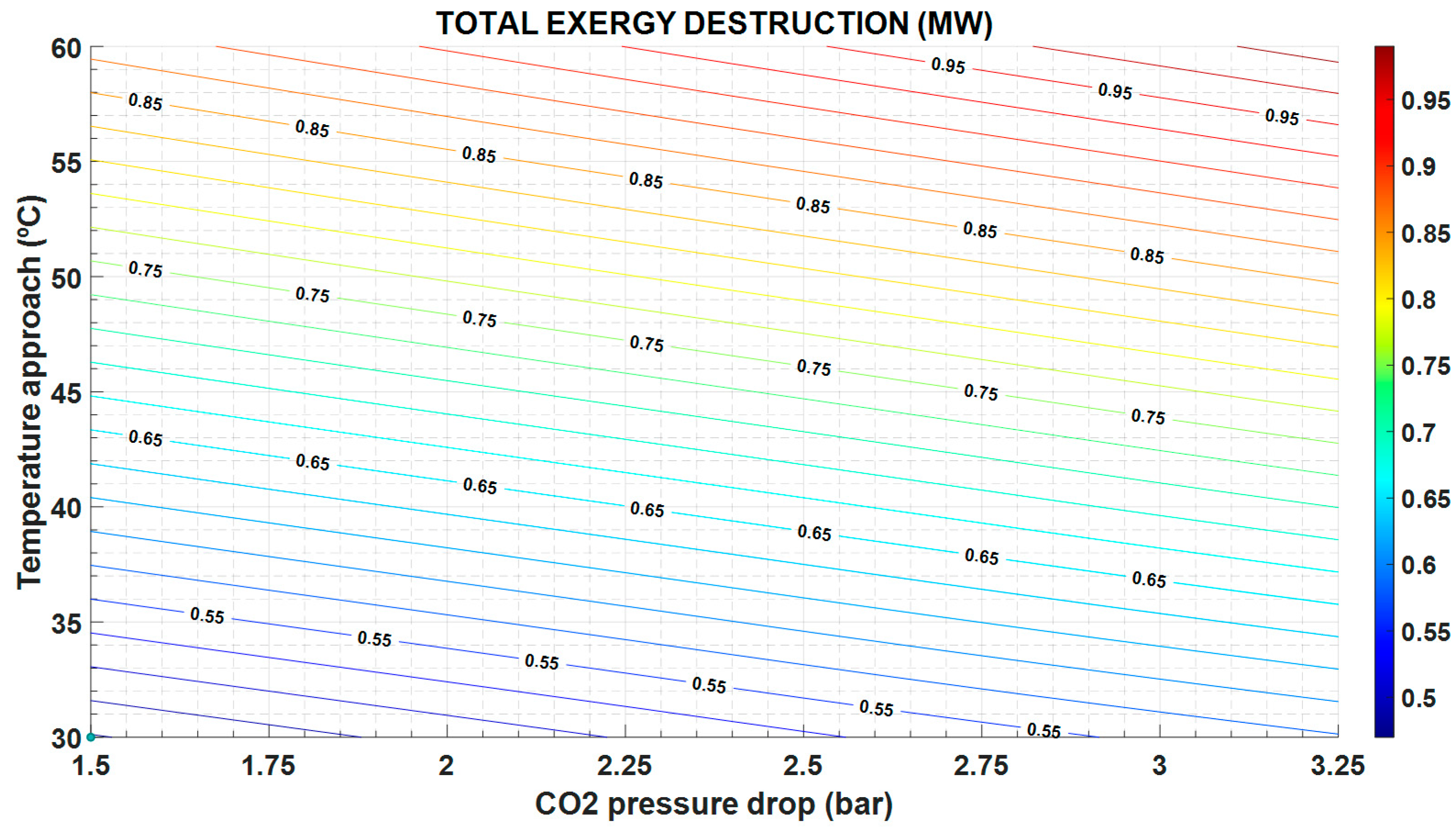
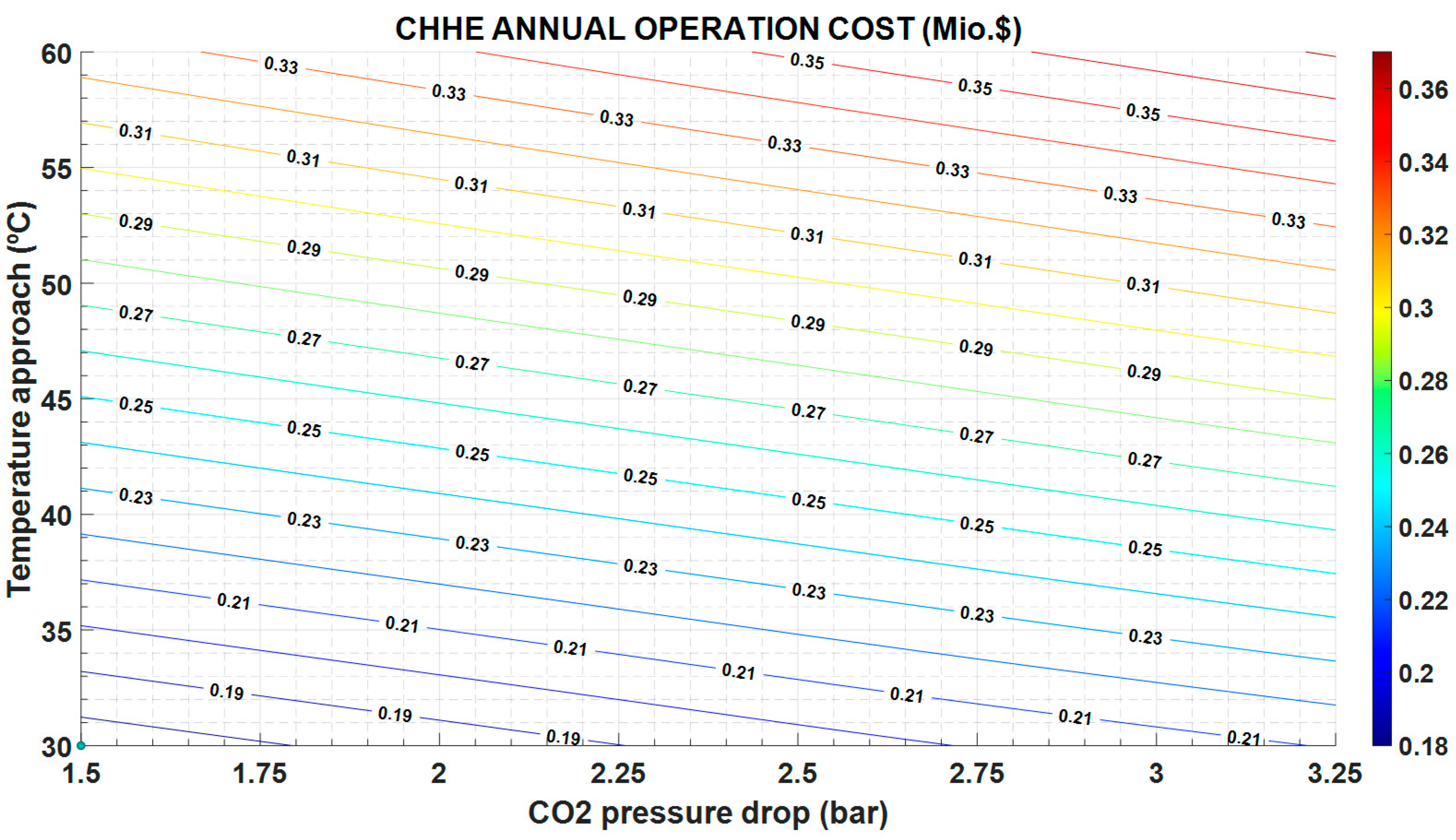
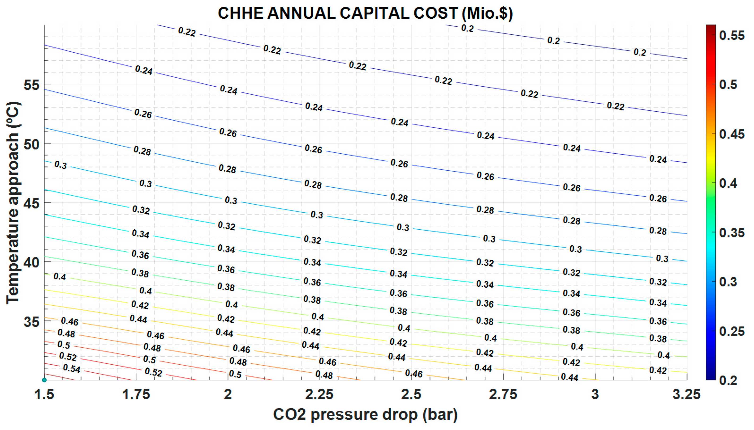
The greater the temperature approach, the higher the exergy destruction (Figure 7) and the operation cost (Figure 8), but the lower the capital cost because the heat exchange area is also lower (Figure 9).
In the same way, the exergy destruction increases as the pressure drop increases, following expression in Table 5 and Figure 7. Instead, the greater the pressure drop, the lower the heat exchange area and the investment cost (Figure 9).
It is important to note that the exergy destruction increases with a greater pressure drop, since the entropy generation by friction also increases; and with the temperature difference between the two streams in the HX, as shown in the Figure 7.
The exergy destruction influences both the operation and maintenance cost and the investment cost. As can be seen in Figure 8, the operation and maintenance cost is proportional to the exergy destruction and follows the same variation: it increases with increasing exergy destruction. However, the investment cost in CHHE decreases as exergy destruction increases, as shown in Figure 9; in this case, a cheaper CHEE (due to smaller dimensions) also exhibits a more limited performance.
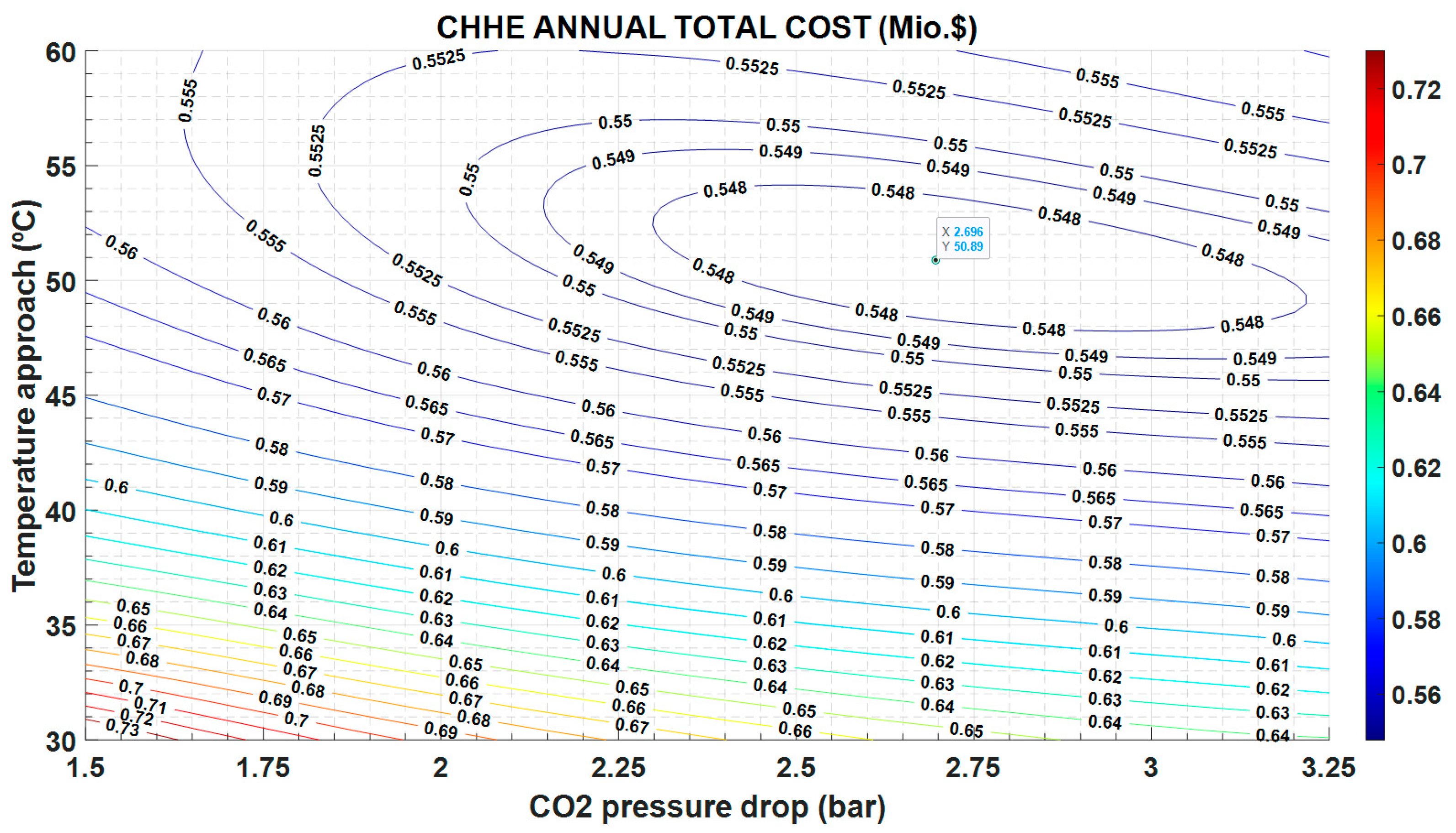
This different trend in O&M costs versus investment costs, yields to the minimum in the annual total cost observed in Figure 10.
Figure 10 plots the results of the optimization, showing that there is a minimum value for the ATC equal to 0.547 Mio.$, for 2.7 bar and 51 °C, approximately. These working conditions are very different of those reported in other type of HXs [24], in which pressure drop is 0.5 bar, whereas the temperature difference is 10 °C, approximately. It must be taken into account that this source heat exchanger only works 12 h a day, as it is located in a STPP, so cost derived of the irreversibilities in the operation are less penalized than if the power plant works continuously.
5. Conclusions
This work presents a new design for the source heat exchanger between the molten salt in the solar field and the supercritical CO2 in a Brayton cycle. This heat exchanger is compact, so the heat transfer of the supercritical phase in enhanced; and, at the same time, the molten salt duct is large enough to avoid plugging problems. This last characteristic is the main advantage of this design compared to other designs presented in the bibliography, since it allows the technological viability of this type of STPP based on a MS solar field and a sCO2 cycle.
The structure best suited to the above requirements is the honeycomb: the thermal unit of this compact heat exchanger consists of a circular channel for the molten salt, surrounded by 6 trapezoidal channels for the CO2. The thermal model of this new Compact Honeycomb Heat Exchanger (CHHE) is implemented and explained.
It is important note that the objective of this design is not to attain the highest heat transfer performance, but the technical feasibility of the heat transfer between a supercritical fluid, at high pressure, and a viscous liquid, that can cause plugging in the small channels of a CHX.
An economic optimization of the CHHE is also accomplished. Previous to this optimization procedure the main sources of exergy destruction have been identified: the temperature approach between both streams and the pressure drop on both fluids. If an exergy cost is defined and assigned to these irreversibilities, they can be included as an operation cost, that can be compared to the initial investment cost. In this way, the objective function Annual Total Cost is minimized as a function of the two thermal inputs: TAMS-CO2 and dPCO2. Results show that there is a minimum for 2.7 bar and 51 °C, approximately. These values are higher than others reported in bibliography, probably because the operational cost are lower, as the operation period of this STTP is lower than that of a conventional power plant.
Other future works include a numerical CFD model to validate the analytical model described in this paper, and to show possible thermo-mechanical problems. A later objective would be to build a laboratory scale model to obtain empirical results.
Author Contributions
Conceptualization, M.J.M. and J.I.L.; methodology, M.J:M.; software, M.J.M. and J.I.L.; validation, R.B. and B.Y.M.; formal analysis, M.J.M.; investigation, R.B. and B.Y.M.; resources, R.B.; data curation, B.Y.M.; writing—original draft preparation, M.J.M.; writing—review and editing, J.I.L.; visualization, M.J.M. supervision, J.I.L.; project administration, M.J.M.; funding acquisition, M.J.M. All authors have read and agreed to the published version of the manuscript.
Funding
This work has been developed in the frame of the ACES2030-CM project, funded by the Regional Research and Development in Technology Programme 2018 (ref. P2018/EMT-4319).
Conflicts of Interest
The authors declare no conflict of interest.
Nomenclature
| Acronyms | |
| ATC | Annual Total Cost |
| CELF | Constant-escalation levelization factor |
| CFD | Computational Fluid Dynamics |
| CHHE | Compact Honeycomb Heat Exchanger |
| CHX | Compact Heat Exchanger |
| CRF | Capital-recovery factor |
| DOE | U.S Department of Energy |
| HX | Heat Exchanger |
| MS | Molten salt |
| PCHE | Printed Circuit Heat Exchanger |
| SHX | Source Heat Exchanger |
| STHX | Shell and Tube Heat Exchanger |
| STPP | Solar Thermal Power Plant |
| TES | Thermal Energy Storage |
| Latin letters | |
| A | Area (m2) |
| c | Specific heat (J/kg/°C) |
| C | Cost ($) |
| CC | Capital Cost ($) |
| CE | Cost per unit of exergy ($/Wh) |
| CB | Base cost ($) |
| Dh | Hydraulic diameter (m) |
| d | Diameter (m) |
| dP | Pressure Drop (Pa) |
| Exergy (W) | |
| f | Darcy pressure friction loss factor |
| FP | Pressure factor |
| FM | Material of construction factor |
| FL | Tube length correction factor, |
| hconv | Convection heat transfer coefficient (W/m2/°C) |
| ieff | Weighted average capital cost |
| k | Thermal conductivity (W/m/°C) |
| L | Length (m) |
| Mass flow rate (kg/s) | |
| N | Number of heat exchanger elements |
| n | Number of years |
| Nu | Nusselt number |
| p | Pressure (Pa) |
| Pr | Prandtl number |
| Thermal power (W) | |
| rn | Nominal escalation rate |
| Re | Reynolds number |
| T | Temperature (°C) |
| TA | Temperature Approach (°C) |
| U | Overall heat transfer coefficient (W/m2/°C) |
| u | Velocity (m/s) |
| V | Volume (m3) |
| Y | Yearly operation time |
| Greek Letters | |
| ρ | Density (kg/m3) |
| Dynamic viscosity (Pa·s) | |
| Subscripts | |
| ave | Average |
| net | Net |
| p | Pressure |
| th | Thermal |
References
- Mehos, M.; Turchi, C.; Vidal, J.; Wagner, M.; Ma, Z.; Ho, C.; Kolb, W.; Andraka, C.; Kruizenga, A. Concentrating Solar Power Gen3 Demonstration Roadmap (No. NREL/TP--5500-67464, 1338899); National Renewable Energy Lab. (NREL): Golden, CO, USA, 2017. [CrossRef] [Green Version]
- Turchi, C.S.; Vidal, J.; Bauer, M. Molten salt power towers operating at 600–650 °C: Salt selection and cost benefits. Solar Energy 2018, 164, 38–46. [Google Scholar] [CrossRef]
- Ehsan, M.M.; Guan, Z.; Gurgenci, H.; Klimenko, A. Feasibility of dry cooling in supercritical CO2 power cycle in concentrated solar power application: Review and a case study. Renew. Sustain. Energy Rev. 2020, 132, 110055. [Google Scholar] [CrossRef]
- Wang, K.; He, Y.-L.; Zhu, H.-H. Integration between supercritical CO2 Brayton cycles and molten salt solar power towers: A review and a comprehensive comparison of different cycle layouts. Appl. Energy 2017, 195, 819–836. [Google Scholar] [CrossRef]
- Neises, T.; Turchi, C. Supercritical carbon dioxide power cycle design and configuration optimization to minimize levelized cost of energy of molten salt power towers operating at 650 °C. Solar Energy 2019, 181, 27–36. [Google Scholar] [CrossRef]
- Linares, J.I.; Montes, M.J.; Cantizano, A.; Sánchez, C. A novel supercritical CO2 recompression Brayton power cycle for power tower concentrating solar plants. Appl. Energy 2020, 263, 114644. [Google Scholar] [CrossRef]
- Kakaç, S.; Liu, H.; Pramuanjaroenkij, A. Heat Exchangers: Selection, Rating, and Thermal Design, 3rd ed.; CRC Press: Hoboken, NJ, USA, 2012. [Google Scholar]
- Du, B.-C.; He, Y.-L.; Qiu, Y.; Liang, Q.; Zhou, Y.-P. Investigation on heat transfer characteristics of molten salt in a shell-and-tube heat exchanger. Int. Commun. Heat Mass Transf. 2018, 96, 61–68. [Google Scholar] [CrossRef]
- Rajeh, T.; Tu, P.; Lin, H.; Zhang, H. Thermo-Fluid Characteristics of High Temperature Molten Salt Flowing in Single-Leaf Type Hollow Paddles. Entropy 2018, 20, 581. [Google Scholar] [CrossRef] [Green Version]
- Le Pierres, R.; Southall, D.; Osborne, S. Impact of Mechanical Design Issues on Printed Circuit Heat Exchangers. In Proceedings of the SCO2 Power Cycle Symposium, University of Colorado at Boulder—University Memorial Center, Boulder, CO, USA, 24–25 May 2011. [Google Scholar]
- Southall, D.; Le Pierres, R.; Dewson, S.J. Design considerations for compact heat exchangers. International Congress on Advances in Nuclear Power Plants, American Nuclear Society. ICAPP’08. In Proceedings of the 2008 International Congress on advances in Nuclear Power Plants, Anaheim, CA, USA, 8–12 June 2008. [Google Scholar]
- Challenges Related to the Use of Liquid Metal and Molten Salt Coolants in Advanced Reactors: Report of the Collaborative Project COOL of the International Project on Innovative Nuclear Reactors and Fuel Cycles (INPRO); International Project on Innovative Nuclear Reactors and Fuel Cycles; International Atomic Energy Agency: Vienna, Austria, 2013.
- Iverson, B.D.; Conboy, T.M.; Pasch, J.J.; Kruizenga, A.M. Supercritical CO2 Brayton cycles for solar-thermal energy. Appl. Energy 2013, 111, 957–970. [Google Scholar] [CrossRef] [Green Version]
- Fu, Q.; Ding, J.; Lao, J.; Wang, W.; Lu, J. Thermal-hydraulic performance of printed circuit heat exchanger with supercritical carbon dioxide airfoil fin passage and molten salt straight passage. Appl. Energy 2019, 247, 594–604. [Google Scholar] [CrossRef]
- Wang, W.-Q.; Qiu, Y.; He, Y.-L.; Shi, H.-Y. Experimental study on the heat transfer performance of a molten-salt printed circuit heat exchanger with airfoil fins for concentrating solar power. Int. J. Heat Mass Transf. 2019, 135, 837–846. [Google Scholar] [CrossRef]
- Shi, H.-Y.; Li, M.-J.; Wang, W.-Q.; Qiu, Y.; Tao, W.-Q. Heat transfer and friction of molten salt and supercritical CO2 flowing in an airfoil channel of a printed circuit heat exchanger. Int. J. Heat Mass Transf. 2020, 150, 119006. [Google Scholar] [CrossRef]
- Sun, X.; Zhang, X.; Christensen, R.; Anderson, M. Compact Heat Exchanger Design and Testing for Advanced Reactors and Advanced Power Cycles (No. 13–5101, 1437159); USDOE Office of Nuclear Energy (United States): Washington, DC, USA, 2018. Available online: https://www.osti.gov/servlets/purl/1437159 (accessed on 9 August 2020).
- Hesselgreaves, J.E. Compact Heat Exchangers: Selection, Design, and Operation, 2nd ed.; Elsevier/BH: Amsterdam, The Netherlands, 2017. [Google Scholar]
- NIST Database. Available online: https://webbook.nist.gov/chemistry/ (accessed on 1 July 2020).
- Sun, H.; Wang, J.; Li, Z.; Zhang, P.; Su, X. Corrosion behavior of 316SS and Ni-based alloys in a ternary NaCl-KCl-MgCl2 molten salt. Solar Energy 2018, 171, 320–329. [Google Scholar] [CrossRef]
- Haynes International. Available online: https://www.haynesintl.com/ (accessed on 1 July 2020).
- ASME Boiler and Pressure Vessel Committee, American Society of Mechanical Engineers, ASME Boiler and Pressure Vessel Committee, Subcommittee on Pressure Vessels. Rules for Construction of Pressure Vessels; An international code VIII, Division 1 VIII, Division 1; American Society of Mechanical Engineers: New York, NY, USA, 2010. [Google Scholar]
- Pacheco, J.E.; Ralph, M.E.; Chavez, J.M.; Dunkin, S.R.; Rush, E.E.; Ghanbari, C.M.; Matthews, M.W. Results of Molten Salt Panel and Component Experiments for Solar Central Receivers: Cold Fill, Freeze/thaw, Thermal Cycling and Shock, and Instrumentation Tests (No. SAND--94-2525, 46671); Sandia National Labs.: Albuquerque, NM, USA, 1995. [Google Scholar] [CrossRef] [Green Version]
- Medrano, M.; Puente, D.; Arenaza, E.; Herrazti, B.; Paule, A.; Brañas, B.; Orden, A.; Domínguez, M.; Stainsby, R.; Maisonnier, D.; et al. Power conversion cycles study for He-cooled reactor concepts for DEMO. Fusion Eng. Des. 2007, 82, 2689–2695. [Google Scholar] [CrossRef]
- Ariu, V. Heat Exchanger Analysis for Innovative Molten Salt Fast Reactor. Master Thesis, ETH Zürich–EPF, Lausanne, Switzerland, 2014. [Google Scholar]
- Gnielinski, V. New equations for heat and mass transfer in turbulent pipe and channel flow. Int. Chem. Eng. 1976, 16, 359–368. [Google Scholar]
- Özçelik, Y. Exergetic optimization of shell and tube heat exchangers using a genetic based algorithm. Appl. Therm. Eng. 2007, 27, 1849–1856. [Google Scholar] [CrossRef]
- Ashrafizadeh, S.A. Application of Second Law Analysis in Heat Exchanger Systems. Entropy 2019, 21, 606. [Google Scholar] [CrossRef] [Green Version]
- Bejan, A. Fundamentals of exergy analysis, entropy generation minimization, and the generation of flow architecture. Int. J. Energy Res. 2002, 26, 545–565. [Google Scholar] [CrossRef]
- London, A.L.; Shah, R.K. Costs of Irreversibilities in Heat Exchanger Design. Heat Transf. Eng. 1983, 4, 59–73. [Google Scholar] [CrossRef]
- Shah, R.K.; Sekulić, D.P. Fundamentals of Heat Exchanger Design; John Wiley & Sons: Hoboken, NJ, USA, 2003. [Google Scholar]
- Seider, W.D.; Seader, J.D.; Lewin, D.R. Product and Process Design Principles: Synthesis, Analysis, and Evaluation, 2nd ed.; Wiley: New York, NY, USA, 2004. [Google Scholar]
- Kim, E.S.; Oh, C.H.; Sherman, S. Simplified optimum sizing and cost analysis for compact heat exchanger in VHTR. Nucl. Eng. Des. 2008, 238, 2635–2647. [Google Scholar] [CrossRef]
- Yoon, S.-J.; Sabharwall, P.; Kim, E.-S. Numerical study on crossflow printed circuit heat exchanger for advanced small modular reactors. Int. J. Heat Mass Transf. 2014, 70, 250–263. [Google Scholar] [CrossRef]
Figure 1.
Scheme of the complete STPP (Solar Thermal Power Plants) with the CHHE (Compact Honeycomb Heat Exchanger) between the solar field and the sCO2 cycle.
Figure 1.
Scheme of the complete STPP (Solar Thermal Power Plants) with the CHHE (Compact Honeycomb Heat Exchanger) between the solar field and the sCO2 cycle.

Figure 2.
Cross section of the Compact Honeycomb Heat Exchanger and thermal unit.

Figure 3.
Temperature–entropy diagram for the sCO2 cycle, including the source heat exchanger.

Figure 4.
Dimensions of the thermal unit of the CHHE selected. (scale in mm).

Figure 5.
Temperature evolution of the ternary chloride molten salt and the CO2 along the CHHE.

Figure 6.
Specific heat evolution for the supercritical CO2 between 520 °C and 650 °C.

Figure 7.
Exergy destruction in the CHHE, as function of the temperature approach between MS and CO2, and the CO2 pressure drop.
Figure 7.
Exergy destruction in the CHHE, as function of the temperature approach between MS and CO2, and the CO2 pressure drop.

Figure 8.
CHHE annual operation cost, as function of the temperature approach between MS and CO2, and the CO2 pressure drop.
Figure 8.
CHHE annual operation cost, as function of the temperature approach between MS and CO2, and the CO2 pressure drop.

Figure 9.
CHHE annual capital cost, as function of the temperature approach between MS and CO2, and the CO2 pressure drop.
Figure 9.
CHHE annual capital cost, as function of the temperature approach between MS and CO2, and the CO2 pressure drop.

Figure 10.
Annual Total Cost as function of the temperature approach between MS and CO2, and the CO2 pressure drop.
Figure 10.
Annual Total Cost as function of the temperature approach between MS and CO2, and the CO2 pressure drop.


Table 1.
Thermodynamic properties of the state points of the recompression sCO2 cycle.
| Recompression Cycle | |||
|---|---|---|---|
| P (bar) | T (°C) | h (kJ/kg) | |
| 1 | 200 | 688 | 701.3 |
| 2 | 86.2 | 574.1 | 566.5 |
| 3 | 85.8 | 224.2 | 158.4 |
| 4 | 85.4 | 122.9 | 39.09 |
| 5 | 85 | 50 | −80.9 |
| 6 | 201.2 | 118.3 | −41.57 |
| 7 | 200.8 | 219.6 | 117.4 |
| 8 | 200.8 | 212 | 107.2 |
| 9 | 200.8 | 217.7 | 114.9 |
| 10 | 200.4 | 545.6 | 522.9 |
| Cycle power (MWe) | 50.00 | ||
| Source thermal power (MWth) | 100.99 | ||
| Cycle efficiency (%) | 49.57 | ||
Table 2.
Thermal properties of the ternary chloride salt MgCl2/NaCl/KCl. (Source: [2]).
Table 2.
Thermal properties of the ternary chloride salt MgCl2/NaCl/KCl. (Source: [2]).
| Thermal Property | Correlation |
|---|---|
| Specific heat (J/kg/°C) | |
| Density (kg/m3) | |
| Thermal conductivity (W/m/°C) | |
| Dynamic viscosity (Pa·s) |
Table 3.
Main thermal and geometric characteristics of the optimal CHHE simulated.
| CO2-MS COMPACT HONEYCOMB HEAT EXCHANGER | |
|---|---|
| Sizing and geometric characteristics | |
| Number of modules in parallel | 3 |
| Number of modules in series | 2 |
| Shell diameter of each module(m) | 0.96 |
| Length of each module(m) | 12.09 |
| Heat transfer area of each module (m2) | 424.66 |
| Number of channels of each module (MS) | 440 |
| Number of channels of each module (CO2) | 2640 |
| MS circular channel diameter (m) | 0.0127 |
| CO2 trapezoidal channel width (m) | 0.0056 |
| Material | Haynes-242 |
| Thermal characteristics | |
| Thermal power (MWth) | 33.664 |
| Average global heat transfer coefficient (W/m2/°C) | 1564.32 |
| Temperature Approach (°C) | 50.89 |
| Primary (Chloride molten salt) | |
| Maximum velocity (m/s) | 2.49 |
| Primary inlet temperature (°C) | 700 |
| Primary inlet pressure (bar) | 25 |
| Primary mass flow rate (kg/s) | 221.82 |
| Primary outlet temperature (°C) | 571.39 |
| Primary outlet pressure (bar) | 22.44 |
| Primary pressure drop (bar) | 2.56 |
| Average convection heat transfer coefficient (W/m2/°C) | 4360.55 |
| Secondary (CO2) | |
| Maximum velocity (m/s) | 10.27 |
| Secondary inlet temperature (°C) | 520.51 |
| Secondary inlet pressure (bar) | 202.68 |
| Secondary mass flow rate (kg/s) | 209.64 |
| Secondary outlet temperature (°C) | 649.11 |
| Secondary outlet pressure (bar) | 200 |
| Secondary pressure drop (bar) | 2.68 |
| Average convection heat transfer coefficient (W/m2/°C) | 2959 |
Table 4.
Parameters for the thermo-economic analysis and optimization.
| Economic Parameters | |
|---|---|
| Weighted average capital cost ieff (%) | 7 |
| Capital recovery factor CRF (%) | 8.58 |
| Nominal escalation rate (%) | 5 |
| k (%) | 98.13 |
| Constant escalation levelization factor (CELF) | 19.74 |
| Economic life (years) | 25 |
Table 5.
Equations to calculate normalized exergy destruction in a heat exchanger (Source: [32]).
Table 5.
Equations to calculate normalized exergy destruction in a heat exchanger (Source: [32]).
| Finite temperature difference | |
| Pressure drops on hot and cold fluid sides | |
| Heat loss (to environment) |
Table 6.
Parameters for the thermo-economic analysis and optimization.
| Tube Length (ft) | FL |
|---|---|
| 8 | 1.25 |
| 12 | 1.12 |
| 16 | 1.05 |
| 20 | 1.00 |
© 2020 by the authors. Licensee MDPI, Basel, Switzerland. This article is an open access article distributed under the terms and conditions of the Creative Commons Attribution (CC BY) license (http://creativecommons.org/licenses/by/4.0/).
Share and Cite
MDPI and ACS Style
Montes, M.J.; Linares, J.I.; Barbero, R.; Moratilla, B.Y. Optimization of a New Design of Molten Salt-to-CO2 Heat Exchanger Using Exergy Destruction Minimization. Entropy 2020, 22, 883. https://0-doi-org.brum.beds.ac.uk/10.3390/e22080883
AMA Style
Montes MJ, Linares JI, Barbero R, Moratilla BY. Optimization of a New Design of Molten Salt-to-CO2 Heat Exchanger Using Exergy Destruction Minimization. Entropy. 2020; 22(8):883. https://0-doi-org.brum.beds.ac.uk/10.3390/e22080883
Chicago/Turabian StyleMontes, María José, José Ignacio Linares, Rubén Barbero, and Beatriz Yolanda Moratilla. 2020. "Optimization of a New Design of Molten Salt-to-CO2 Heat Exchanger Using Exergy Destruction Minimization" Entropy 22, no. 8: 883. https://0-doi-org.brum.beds.ac.uk/10.3390/e22080883
Note that from the first issue of 2016, this journal uses article numbers instead of page numbers. See further details here.