Stator Winding Fault Phase Identification Using Piezoelectric Sensors in Three-Phase Induction Motors †


Abstract
:1. Introduction
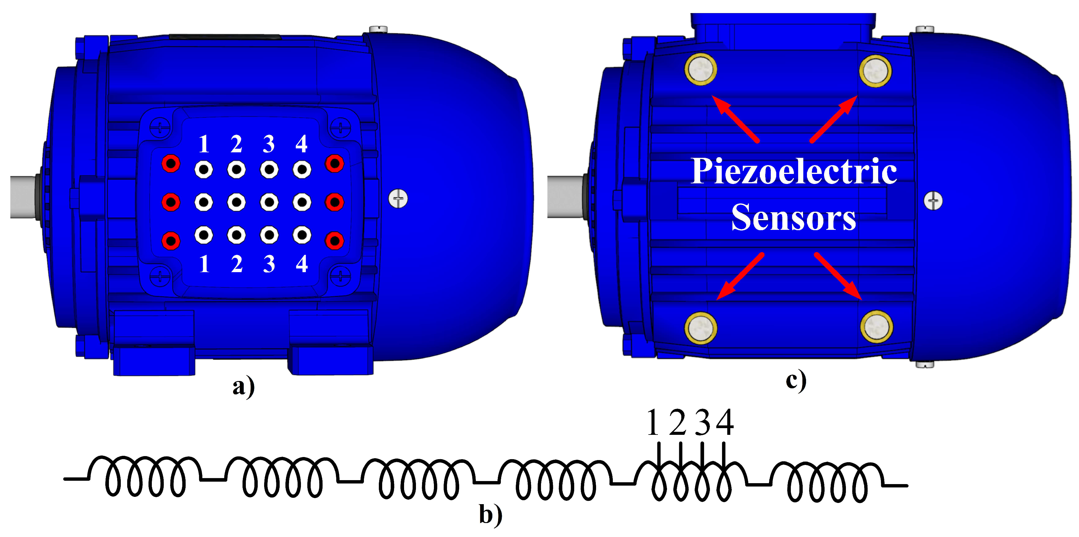
2. Acoustic Sensors
3. Acoustic Signals Analysis
3.1. Fast Fourier Transform
3.2. Signal Energy
4. Experimental Setup
4.1. Test Bench Setup
4.2. Sensor and Data Acquisition
5. Results
6. Conclusions
Funding
Conflicts of Interest
References
- Gangsar, P.; Tiwari, R. A support vector machine based fault diagnostics of Induction motors for practical situation of multi-sensor limited data case. Measurement 2019, 135, 694–711. [Google Scholar] [CrossRef]
- Jiang, C.; Li, S.; Habetler, T.G. A review of condition monitoring of induction motors based on stray flux. In Proceedings of the 2017 IEEE Energy Conversion Congress and Exposition (ECCE), Cincinnati, OH, USA, 1–5 October 2017. [Google Scholar] [CrossRef]
- Chen, J.; Hu, N.; Zhang, L.; Chen, L.; Wang, B.; Zhou, Y. A Method for Broken Rotor Bars Diagnosis Based on Sum-Of-Squares of Current Signals. Appl. Sci. 2020, 10, 5980. [Google Scholar] [CrossRef]
- Dorrell, D.G.; Makhoba, K. Detection of Inter-Turn Stator Faults in Induction Motors Using Short-Term Averaging of Forward and Backward Rotating Stator Current Phasors for Fast Prognostics. IEEE Trans. Magn. 2017, 53, 1–7. [Google Scholar] [CrossRef]
- Xu, Z.; Hu, C.; Yang, F.; Kuo, S.H.; Goh, C.K.; Gupta, A.; Nadarajan, S. Data-Driven Inter-Turn Short Circuit Fault Detection in Induction Machines. IEEE Access 2017, 5, 25055–25068. [Google Scholar] [CrossRef]
- Gangsar, P.; Tiwari, R. Signal based condition monitoring techniques for fault detection and diagnosis of induction motors: A state-of-the-art review. Mech. Syst. Signal Process. 2020, 144, 106908. [Google Scholar] [CrossRef]
- Ali, M.Z.; Shabbir, M.N.S.K.; Liang, X.; Zhang, Y.; Hu, T. Machine Learning-Based Fault Diagnosis for Single- and Multi-Faults in Induction Motors Using Measured Stator Currents and Vibration Signals. IEEE Trans. Ind. Appl. 2019, 55, 2378–2391. [Google Scholar] [CrossRef]
- Fraden, J. Handbook of Modern Sensors: Physics, Designs, and Applications; Springer: Cham, Switzerland; New York, NY, USA, 2016. [Google Scholar]
- Carvalho, L.; Lucas, G.; Rocha, M.; Fraga, C.; Andreoli, A. Undervoltage Identification in Three Phase Induction Motor Using Low-Cost Piezoelectric Sensors and STFT Technique. Proceedings 2019, 42, 72. [Google Scholar] [CrossRef]
- Zhen, D.; Wang, Z.; Li, H.; Zhang, H.; Yang, J.; Gu, F. An Improved Cyclic Modulation Spectral Analysis Based on the CWT and Its Application on Broken Rotor Bar Fault Diagnosis for Induction Motors. Appl. Sci. 2019, 9, 3902. [Google Scholar] [CrossRef]
- Proakis, J. Digital Signal Processing; Pearson Prentice Hall: Upper Saddle River, NJ, USA, 2007. [Google Scholar]
- Ewert, P.; Kowalski, C.T.; Orlowska-Kowalska, T. Low-Cost Monitoring and Diagnosis System for Rolling Bearing Faults of the Induction Motor Based on Neural Network Approach. Electronics 2020, 9, 1334. [Google Scholar] [CrossRef]
- Gonzalez-Toral, R.; Reviriego, P.; Maestro, J.A.; Gao, Z. A Scheme to Design Concurrent Error Detection Techniques for the Fast Fourier Transform Implemented in SRAM-Based FPGAs. IEEE Trans. Comput. 2018, 67, 1039–1045. [Google Scholar] [CrossRef]
- Lucas, G.B.; de Castro, B.A.; Rocha, M.A.; Andreoli, A.L. Three-phase induction motor loading estimation based on Wavelet Transform and low-cost piezoelectric sensors. Measurement 2020, 164, 107956. [Google Scholar] [CrossRef]
- Zhao, M.; Xu, G. Feature extraction of power transformer vibration signals based on empirical wavelet transform and multiscale entropy. IET Sci. Meas. Technol. 2018, 12, 63–71. [Google Scholar] [CrossRef]


Disclaimer/Publisher’s Note: The statements, opinions and data contained in all publications are solely those of the individual author(s) and contributor(s) and not of MDPI and/or the editor(s). MDPI and/or the editor(s) disclaim responsibility for any injury to people or property resulting from any ideas, methods, instructions or products referred to in the content. |
© 2020 by the authors. Licensee MDPI, Basel, Switzerland. This article is an open access article distributed under the terms and conditions of the Creative Commons Attribution (CC BY) license (https://creativecommons.org/licenses/by/4.0/).
Share and Cite
Lucas, G.; Rocha, M.; Castro, B.; Leão, J.; Andreoli, A. Stator Winding Fault Phase Identification Using Piezoelectric Sensors in Three-Phase Induction Motors. Eng. Proc. 2020, 2, 32. https://0-doi-org.brum.beds.ac.uk/10.3390/ecsa-7-08183
Lucas G, Rocha M, Castro B, Leão J, Andreoli A. Stator Winding Fault Phase Identification Using Piezoelectric Sensors in Three-Phase Induction Motors. Engineering Proceedings. 2020; 2(1):32. https://0-doi-org.brum.beds.ac.uk/10.3390/ecsa-7-08183
Chicago/Turabian StyleLucas, Guilherme, Marco Rocha, Bruno Castro, José Leão, and André Andreoli. 2020. "Stator Winding Fault Phase Identification Using Piezoelectric Sensors in Three-Phase Induction Motors" Engineering Proceedings 2, no. 1: 32. https://0-doi-org.brum.beds.ac.uk/10.3390/ecsa-7-08183