
Review on Interface and Interphase Issues in Sulfide Solid-State Electrolytes for All-Solid-State Li-Metal Batteries


Materials Sciences Division, Lawrence Berkeley National Laboratory, Berkeley, CA 94720, USA
*
Author to whom correspondence should be addressed.
Electrochem 2021, 2(3), 452-471; https://0-doi-org.brum.beds.ac.uk/10.3390/electrochem2030030
Submission received: 7 July 2021
/
Revised: 21 July 2021
/
Accepted: 23 July 2021
/
Published: 2 August 2021
(This article belongs to the Collection Feature Papers in Electrochemistry)
Abstract
:All-solid-state batteries have emerged as promising alternatives to conventional Li-ion batteries owing to their higher energy density and safety, which stem from their use of inorganic solid-state electrolytes instead of flammable organic liquid electrolytes. Among various candidates, sulfide solid-state electrolytes are particularly promising for the development of high-energy all-solid-state Li metal batteries because of their high ionic conductivity and deformability. However, a significant challenge remains as their inherent instability in contact with electrodes forms unstable interfaces and interphases, leading to degradation of the battery performance. In this review article, we provide an overview of the key issues for the interfaces and interphases of sulfide solid-state electrolyte systems as well as recent progress in understanding such interface and interphase formation and potential solutions to stabilize them. In addition, we provide perspectives on future research directions in this field.
1. Introduction
For decades, rechargeable lithium-ion batteries (LIBs) using organic liquid electrolytes have been commercially used as a power source for portable electronic devices [1,2,3], and their use has recently expanded to mid–large-scale electrochemical energy storage applications, including electric vehicles (EVs) and grids [4,5]. For the success of EVs, battery technology must surpass the current limitation of driving ranges by achieving a larger capacity. According to a global technical goal for 2030, the specific energy of secondary batteries must reach 500 Wh kg−1, which is much higher than the 246 Wh kg−1 of today’s typical EV batteries used in the Tesla Model 3 [6,7,8,9]. To achieve such a high energy density, a Li-metal anode is considered to be an unrivaled component, owing mainly to its extremely high theoretical specific capacity (3860 mAh g−1) and lowest reduction potential (−3.040 V vs. the standard hydrogen electrode). Safety issues have become more important than ever as battery sizes have increased. However, current LIB technology using liquid electrolytes cannot meet the requirements for the use of a Li-metal anode or safety [10,11].
In this respect, all-solid-state batteries (ASSBs), which use inorganic solid-state electrolytes (SSEs) instead of flammable organic liquid electrolytes, have emerged as promising alternatives to conventional LIBs. SSEs offer several advantages over conventional liquid electrolytes. First, ASSBs are stable even in extreme environmental conditions such as high pressure, temperature, overcharge, or external shock, and there is much less risk of ignition or explosion [12,13]. Second, it is believed that ASSBs can use a Li-metal anode since the sufficient stiffness of SSEs can mitigate the internal short circuit by suppressing the Li dendrite growth during the electrochemical cycles [14]. Third, the volumetric energy density can be improved by reducing its volume since there is no need to pack each cell and a simpler design through bipolar stacking is available for ASSBs [15,16]. Despite these advantages of ASSBs, important challenges remain to be addressed. Many SSEs display lower ionic conductivity at room temperature when compared to liquid electrolytes. Moreover, it is difficult to ensure the ion-transfer channel between the SSE and electrodes because of their unstable interfaces.
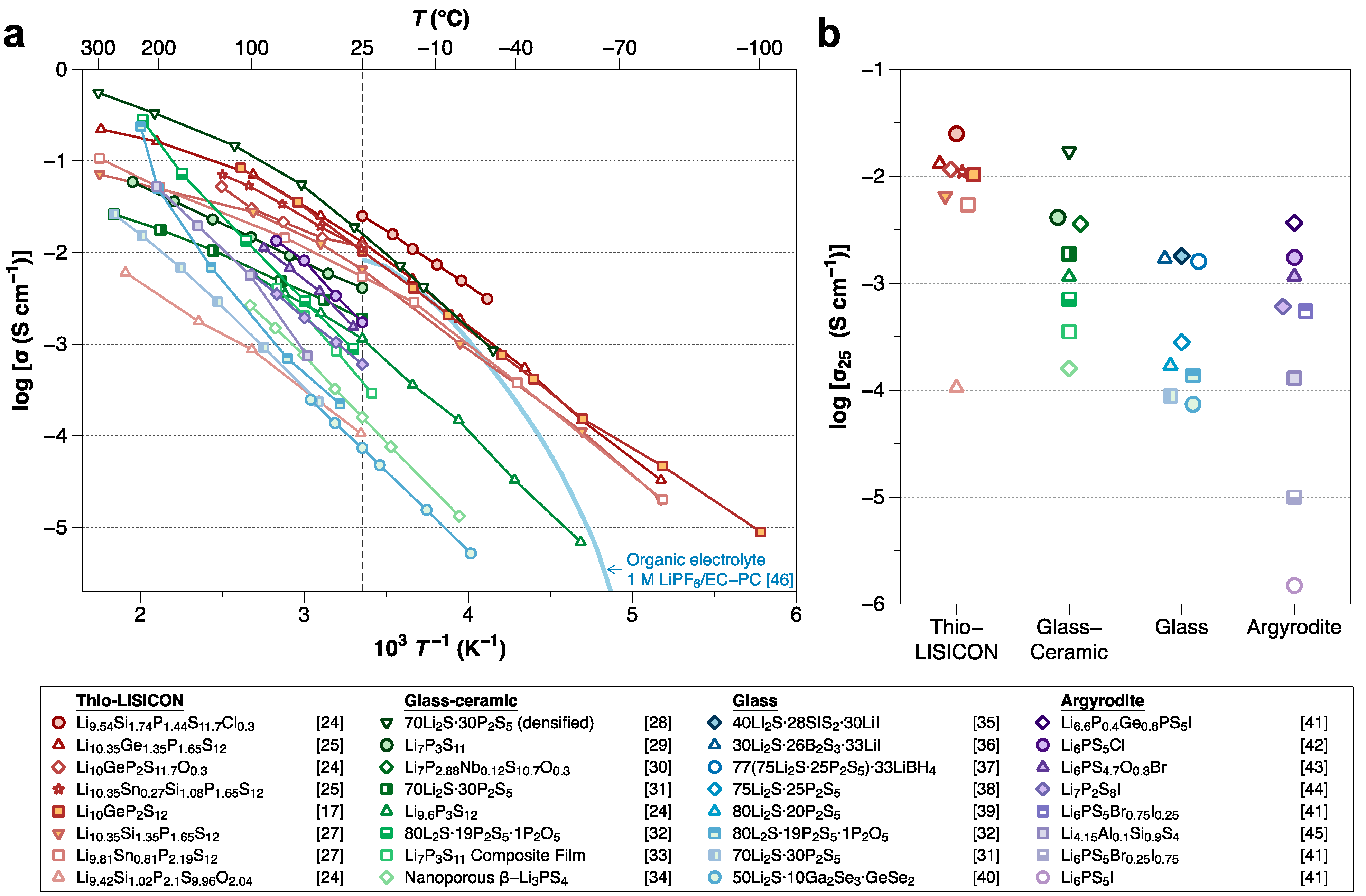
Of the various kinds of SSEs, sulfide SSEs have attracted significant attention due to their high ionic conductivity (10−2–10−4 S cm−1), which is comparable to that of organic liquid electrolytes [11,17,18]. Figure 1 summarizes the ionic conductivities of sulfide SSEs. Although the high ionic conductivity and deformability make sulfide compounds promising SSEs, several important challenges remain. Sulfide SSEs have an intrinsically narrow electrochemical stability window, which results in undesired (electro)chemical reactions between the sulfide SSE and electrodes during battery cycling [19], forming unstable interphases. Such interphase formation leads to operation failures of ASSBs. Therefore, considerable efforts are now focused on improving the interfacial stabilities between sulfide SSEs and electrode materials.
In this review, we present an overview of the limitations and recent achievements in the development of sulfide SSEs, with a particular focus on the stability issue of sulfide SSEs with lithium-metal anodes and various cathode active materials. We will not discuss the conductivities of sulfide SSEs, as this topic is already well documented in previous review articles [11,20,21,22,23]. We further discuss recently proposed techniques to achieve a favorable interface between sulfide SSEs and electrodes in ASSBs. This review aims to provide not only a comprehensive description of the developments of sulfide SSEs but also insight into potential directions of future research.
2. Electrochemical Stability of Sulfide SSEs
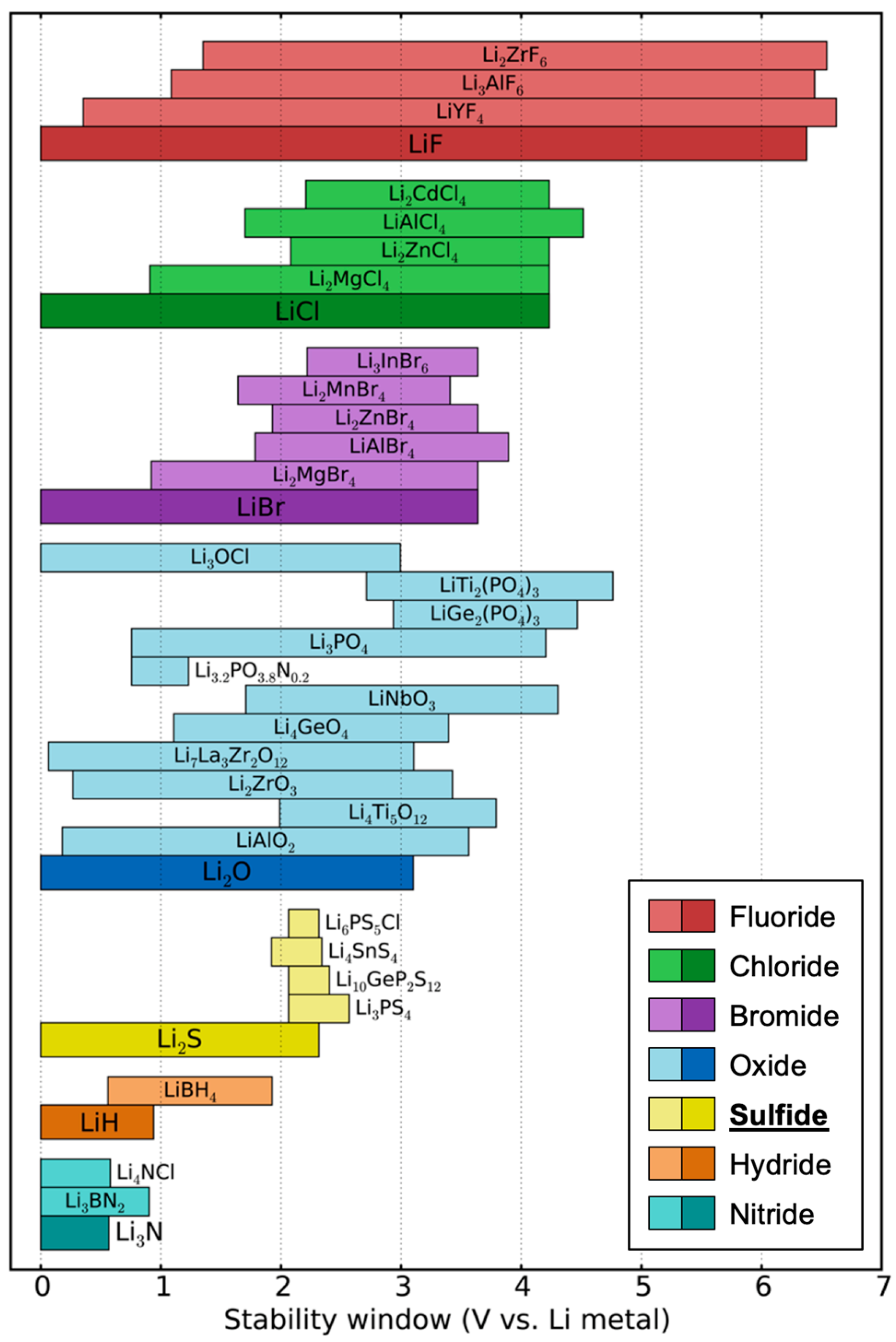
The greatest challenge for sulfide SSEs is their very narrow electrochemical stability window, which leads to poor compatibility with electrodes. Although early works claimed that sulfide SSEs have a good electrochemical stability window of 0–4 V (vs. Li metal) based on cyclic voltammetry (CV) measurements [17,28,47], it is highly likely that these works overestimated their electrochemical stability. In the CV tests, the planar electrode geometry limits the contact area, leading to small currents, which can show kinetically extended electrochemical stability instead of a thermodynamic stability window. Later, Han et al. and Dewald et al. proved that the electrochemical stability windows of sulfide SSEs are indeed much narrower than those determined by previous CV tests [48,49]. To increase the ‘active’ contact area, they mixed Li10GeP2S12 (LGPS) thiophosphate and carbon and measured the CV of the mixture, which presented a much lower oxidation limit (<2.5 V vs. Li). In the mixture of LGPS–carbon, LGPS provides Li-transport pathways and carbon works for electron transfer. Therefore, such a configuration could show a ‘practical’ electrochemical stability window. This is critical since SSEs will encounter carbon additives in the cathode composite of ASSBs. Computational works have also demonstrated that sulfide SSEs have a narrow electrochemical stability window when compared with oxides and halides, as shown in Figure 2 [19,50,51]. Such a narrow electrochemical stability window is a major practical disadvantage of sulfide SSEs since the electrolyte must be stable over a wide range of lithium potentials between the anode chemical potential (0 eV/atom vs. Li) and the potential set by the cathode, which is near <−4.0 eV/atom for typical cathodes.
3. Interfacial Stability
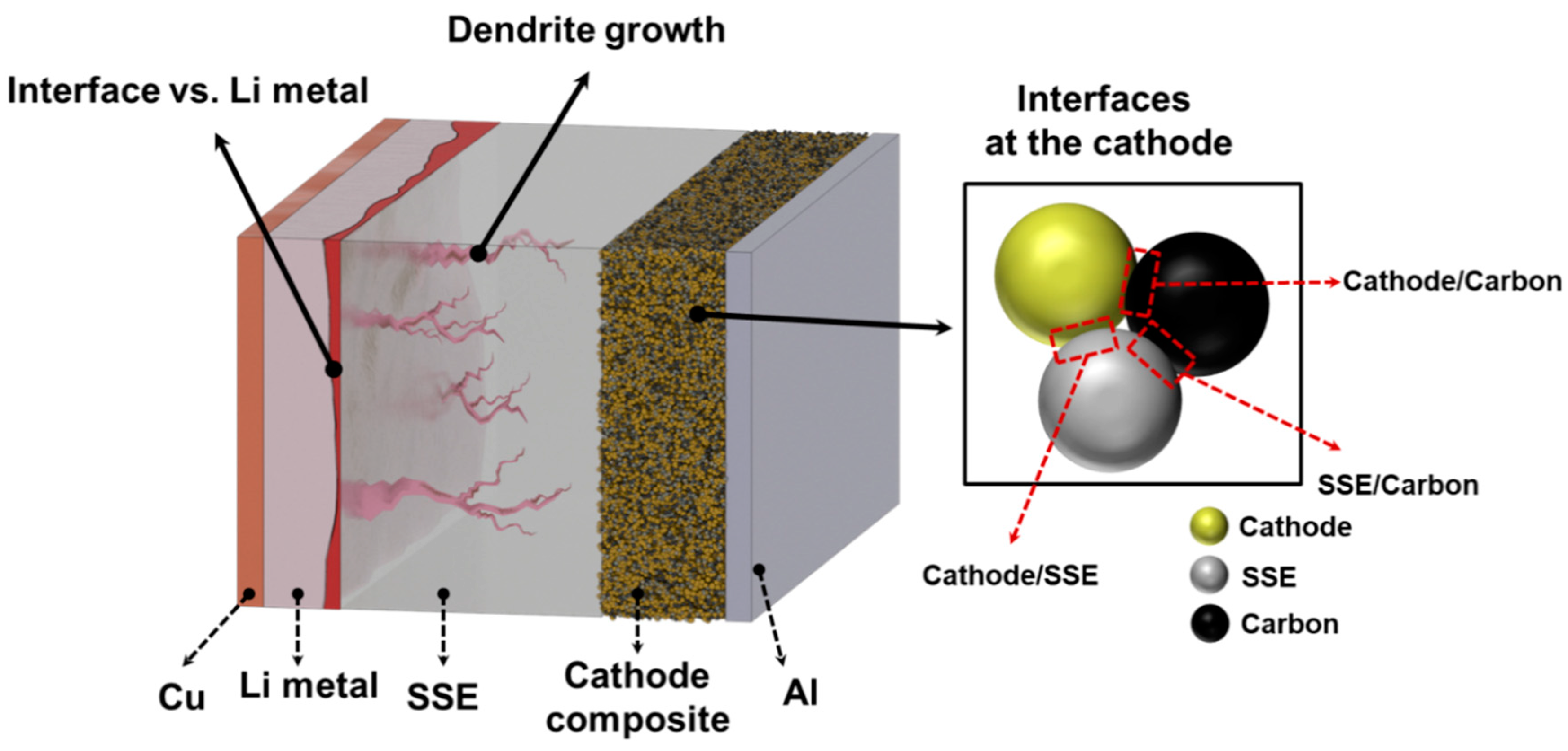
The narrow electrochemical stability window of sulfide SSEs leads to poor compatibility with both the anode and cathode. At the interface with electrodes, sulfide SSEs suffer from significant material degradation when electron-transport pathways are provided. Figure 3 summarizes the interfaces in sulfide-SSE-based ASSBs. With a Li metal anode, sulfide SSEs are reduced and form a solid-electrolyte interphase (SEI) layer between the Li metal and SSE. Depending on the reduction products, the interface can be passivated or cause the continuous reduction of the SSE, thus leading to battery failure [19]. Another important issue at the anode side is dendritic Li growth during the charging of ASSBs. Although it was believed that rigid SSEs could prevent dendritic growth in the early stages of research, many reports have since shown Li dendritic growth and penetration through SSEs [52,53,54,55]. The situation is much more complicated on the cathode composite side. A cathode active material needs to be homogeneously mixed with an SSE and carbon to provide Li-ion and electron pathways. As a result, the cathode composite has more interfaces, namely cathode/SSE, carbon/SSE, and cathode/carbon. We will discuss recent findings of interfacial degradation mechanisms and approaches to overcome them in the following sections.
3.1. Interface with Li-Metal Anode
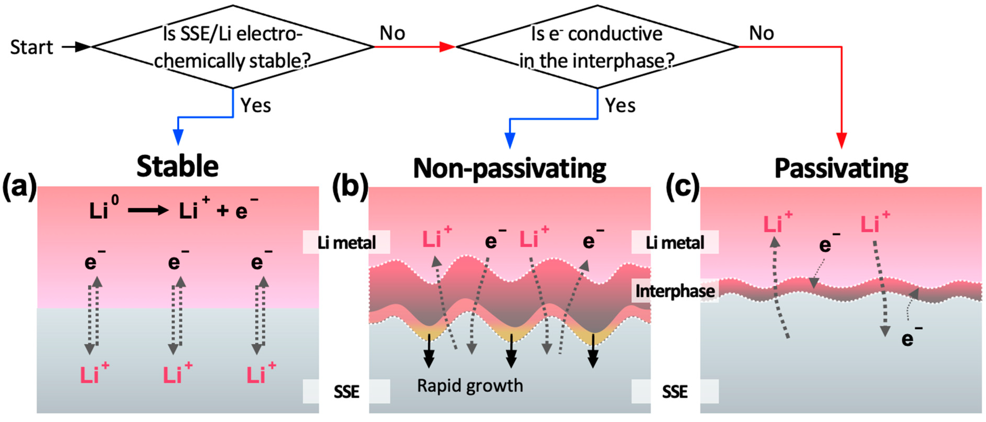
Due to the inherently narrow electrochemical stability window, many sulfide SSEs decompose spontaneously simply by contacting a Li-metal anode [19]. Several efforts have been made to evaluate Li-metal/sulfide-SSE interfaces both theoretically and experimentally [18,50,56,57,58,59,60,61,62,63,64,65,66,67]. The interfaces formed between Li metal and the SSE can be classified into the following three types [68]. Type I interfaces are stable and ideal interfaces formed when the SSE does not react with Li metal electrochemically (Figure 4a). Most binary compounds, including Li2S and Li3P, form this ‘type I’ interface with Li metal. However, if the SSE is not electrochemically stable with Li metal, as most of the sulfide compounds are, the interphase will form at the interface as products of the SSE decompose. If the interphase material is highly conductive for both ionic and electronic transport, non-passivating interphases will form, and the reduction of SSE continuously occurs (Type II). Thus, the reaction front rapidly propagates into the SSE, leading to a short circuit and failure of the SSB (Figure 4b). When the interphases exhibit ionic conductivity but not electrical conductivity (Type III), the interface becomes relatively stable (passivating interphase) because the decomposition reaction of the SSE is suppressed significantly (Figure 4c).
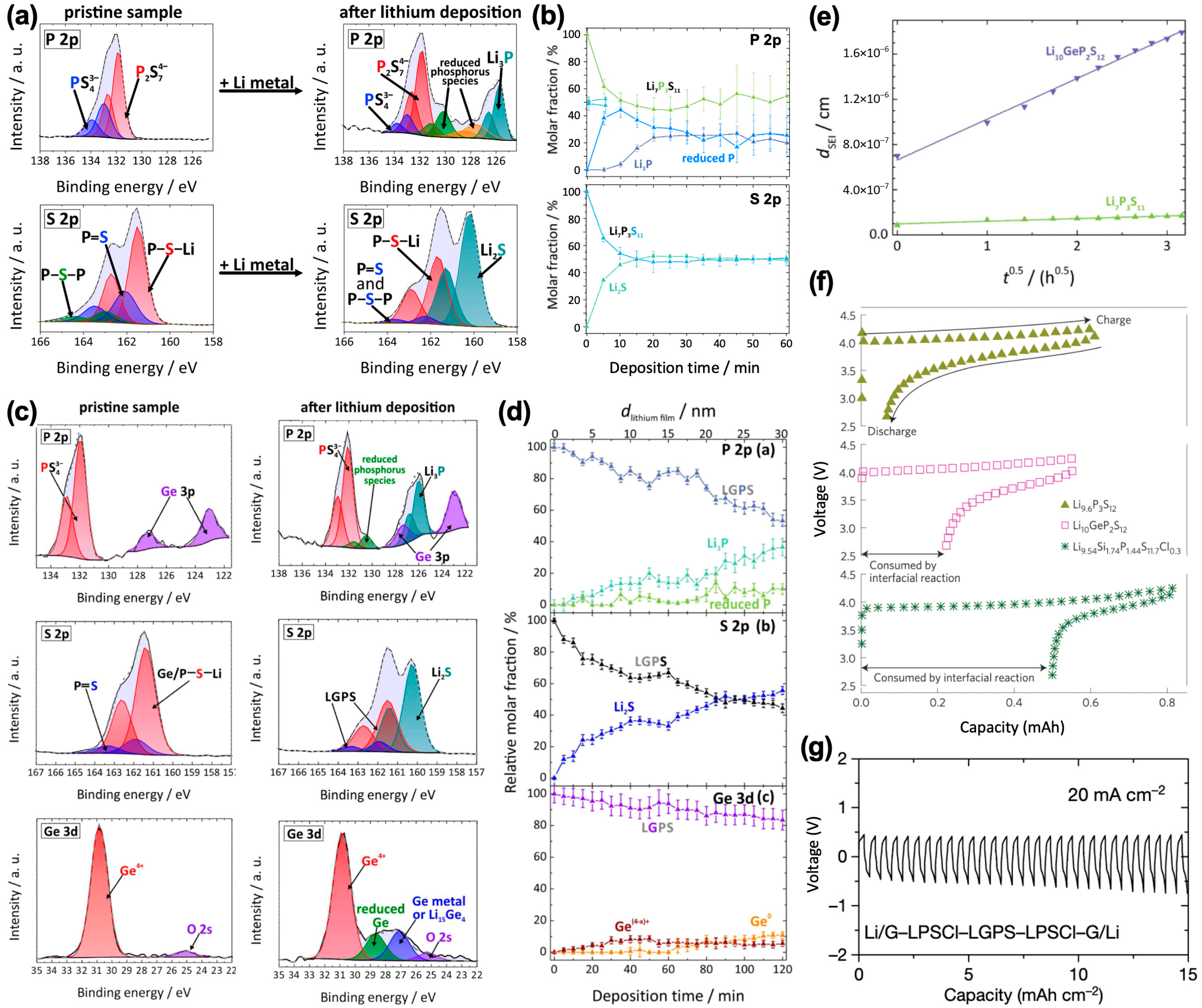
In situ X-ray photoelectron spectroscopy (XPS) measurements during Li vapor deposition of various sulfide SSEs by Wenzel et al. provide experimental evidence of the formation of passivating interphases [69,70,71,72]. For the crystalline Li7P3S11 and Li6PS5X (X = Cl, Br, or I) argyrodites, Li2S, Li3P, and LiX (X = Cl, Br, or I) were formed at the interphase (Figure 5a), consistent with the theoretical predictions [73]. Despite the possible existence of the various reduced P phases in P 2p signals, the authors concluded that this reduced P phase likely originated from the reactions of Li3P with residual oxygen and water in the UHV chamber. Some studies have pointed out that the oxygen (O) contamination in sulfide SSEs can lead to phase segregation in the lithium phosphate (Li3PO4) phase at the initial stage of the interphase formation reaction [74]. It remains debatable whether the oxygen-containing interphase formation should be attributed to the pre-existing oxygen in the sulfide SSEs or contamination from air exposure during the sample transfer. Correlative analysis from time-resolved electrochemical impedance spectroscopy (EIS) and XPS confirms that an increase in the thickness and resistivity of the interphase is gradually slowed down as more Li metal is deposited (Figure 5b) in the Li7P3S11 system, suggesting that their interphase stabilizes the interface themselves (the formation of a passivating interphase). Similar passivating interphase formation has been reported in Li6PS5Cl (LPSCl) and Li6PS5Br [71].
In contrast to the passivating-layer formation of Li7P3S11 and Li-argyrodite (Li6PS5Cl and Li6PS5Br)-related interphases, Li thiophosphates such as LGPS and LSPS (Li10SnP2S12) are known to form a non-passivating interphase upon contact with Li metal due to the presence of components (i.e., Ge4+ and Sn4+) that provide electron-conducting pathways when reduced [71,75]. Wenzel et al. conducted in situ XPS experiments on LGPS material and reported its interfacial instability with Li metal [72]. Figure 5c shows the XPS spectra changes of LGPS before and after deposition of 31-nm Li metal. In addition to the formation of Li3P and Li2S, the reduction of Ge4+ to metallic Ge species is clearly detected and denoted as “reduced Ge” and “Ge metal or Li15Ge4” in Figure 5c. The fraction of Li2S continues to increase even after 2 h (Figure 5d), indicating that the interfacial reaction is not yet finished at the end of the last deposition step and that the SEI is still growing (Figure 5e). Compared with that in germanium-free Li7P3S11, the SEI formed in Li10GeP2S12 grows much faster. It is interesting that the decomposition of LGPS continues given that the amount of Ge reduction measured in this study is much less than the amount of formed Li3P and Li2S. The authors attributed this to the formation of electronically conducting Ge phases that also have high Li diffusivity. Such non-passivating interphase formation leads to the high coulombic loss of LGPS, compared to LPS (specifically, Li9.6P3S12), as shown in Figure 5f [24].
Various solutions have been reported to engineer the compatibility between SSEs and Li metals. For example, Yang et al. suggested antiperovskite lithium oxychloride, Li3OCl, as a potential artificial passivating compound to stabilize the interface between SSEs and Li metal [77]. As also well predicted in Figure 2 (located at the top of the oxides) [19], antiperovskites are theoretically stable at 0 V, owing to the absence of reducible non-Li cations in the composition [10]. In their experiments, Li-symmetric cell shows a stable voltage polarization profile >100 h at 0.035 mA cm−2. However, their approach did not expand on how to incorporate their artificial passivating compound into the full cell systems. Recently, Ye et al. proposed an interesting solution for the poor interfacial stability of sulfide SSEs with Li metal [76]. For example, the Li–LGPS–Li symmetric cell exhibited very poor cyclability at 0.25 mA cm−2 (corresponding to 0.5C), with a voltage spark after 3 cycles. Even for LPSCl, which is well known for being more electrochemically stable, a short-circuit occurred after over 150 h of operation under the same test condition. However, by employing combined strategies of multilayer stacking of the electrolytes, a less-stable electrolyte sandwiched between more-stable SSEs, and covering of the Li-metal anode with a graphite film, the authors demonstrate superior cycling performance for 1800 h under the same condition (0.25 mA−2) without any observable voltage drops for the Li/G–LPSCl–LGPS-LPSCl–G/Li symmetric cell. Further, this cell is also stable for up to 15 h of operation at 20 mA cm−2 (corresponding to 40C, Figure 5g). The authors suggested that the multilayer design can prevent lithium dendrite penetration because the decomposition products of SSEs at the interface between LGPS and LPSCl fill and heal cracks. However, this mechanism has not yet been fully proven.
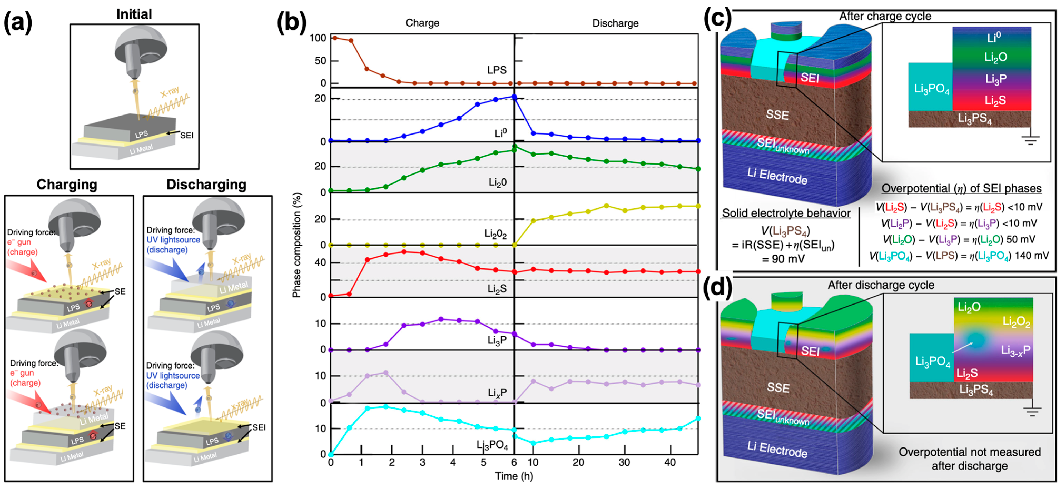
Recently, operando XPS (opXPS) measurements were developed and applied to investigate a Li/Li2S–P2S5 interface by Wood et al. This technique mimics the charging–discharging process of a battery system using an electron gun (for lithium plating, charging) and ultraviolet-light source (for lithium stripping, discharging) [74]. Figure 6a presents schematics of the operando XPS technique employed in this study. By following the general trends in the phase-composition changes during charge/discharge half-cycles (Figure 6b), the opXPS profiles having depth information of the interphase reveal that the interphase has a layered configuration composed of Li0/Li2O/Li3P/Li2S/LPS (Figure 5c). The authors claim that Li2S and Li3P phases form first on the LPS, followed by Li2O phase formation, and finally Li0 deposition. The authors argued that Li2O converts into Li2O2 and that Li3P transforms into the Li-deficient phase Li3−xP via delithiation during discharging (lithium-stripping process), as shown in Figure 6d, since Li2O and Li3P are the redox-active species.
3.2. Li-Dendrite Penetration
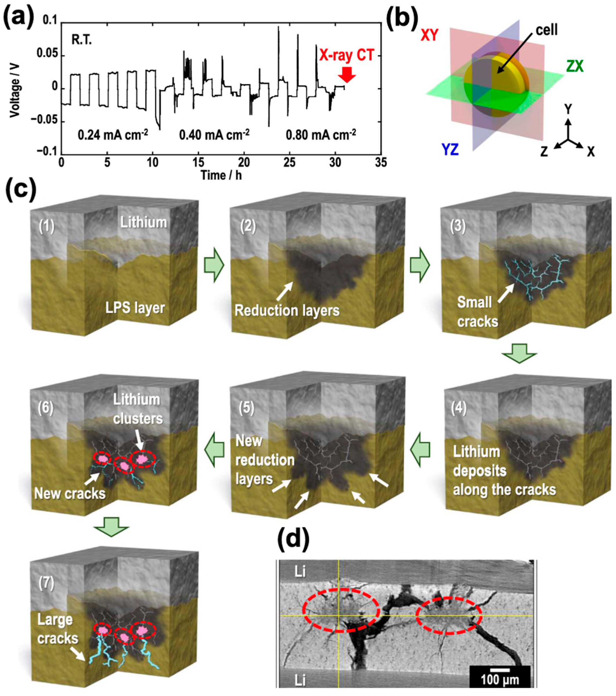
Dendritic Li growth and its penetration through SSEs is a major issue that must be addressed for the commercialization of ASSBs. In general, Li dendrites grow at relatively high current rates even in SSE systems, and the dendrites lead to a short circuit of the battery cell. In addition, the Li dendrite will form a new interface once it penetrates a SSE, and then, it will decompose the SSE and form a SEI layer, which will lead to deterioration of the battery performance. For example, 0.75Li2S–0.25P2S5 glass electrolyte shows a voltage drop in a Li-symmetric cell when the current is larger than 0.4 mA cm−2; this voltage drop indicates the short circuit of the cell [78]. Similarly, other sulfide SSEs have relatively low critical currents (<1.5 mA cm−2) that result in short circuits [79,80,81], which are much lower critical currents than those for liquid electrolytes (>10 mA cm−2) [82] A very recent work by Otoyama et al. confirmed that Li metal can penetrate through the Li3PS4 SSE using in situ X-ray computed tomography (X-ray CT) [83]. Figure 7a presents the galvanostatic cycling results of the Li/Li3PS4/Li symmetric cell under three different current rates of 0.24, 0.40, and 0.80 mA cm−2. Tomograms in the XY, YZ, and ZX planes were obtained from the X-ray CT measurements (Figure 7b). The authors claimed that a crack is formed when Li3PS4 is decomposed in contact with Li metal since the volume expanded. Then, Li metal could easily penetrate the cracks and form new interfaces of Li/Li3PS4. Such a reduction–expansion–cracking reaction is repeated and thus makes large cracks and form Li clusters inside the Li3PS4 electrolyte, finally causing a short circuit (Figure 7c,d). A very recent study by Ning et al. using in situ X-ray CT in Li/Li6PS5Cl/Li system also demonstrated that the cracking is initiated near the surface with the plated electrode, and that the cracks propagate across the electrolyte from the plated to the stripped electrode [84], which agrees well with previous observations [83]. Similarly, Kazyak et al. observed Li dendrite penetration through Li3PS4 electrolyte using operando optical microscopy [54].
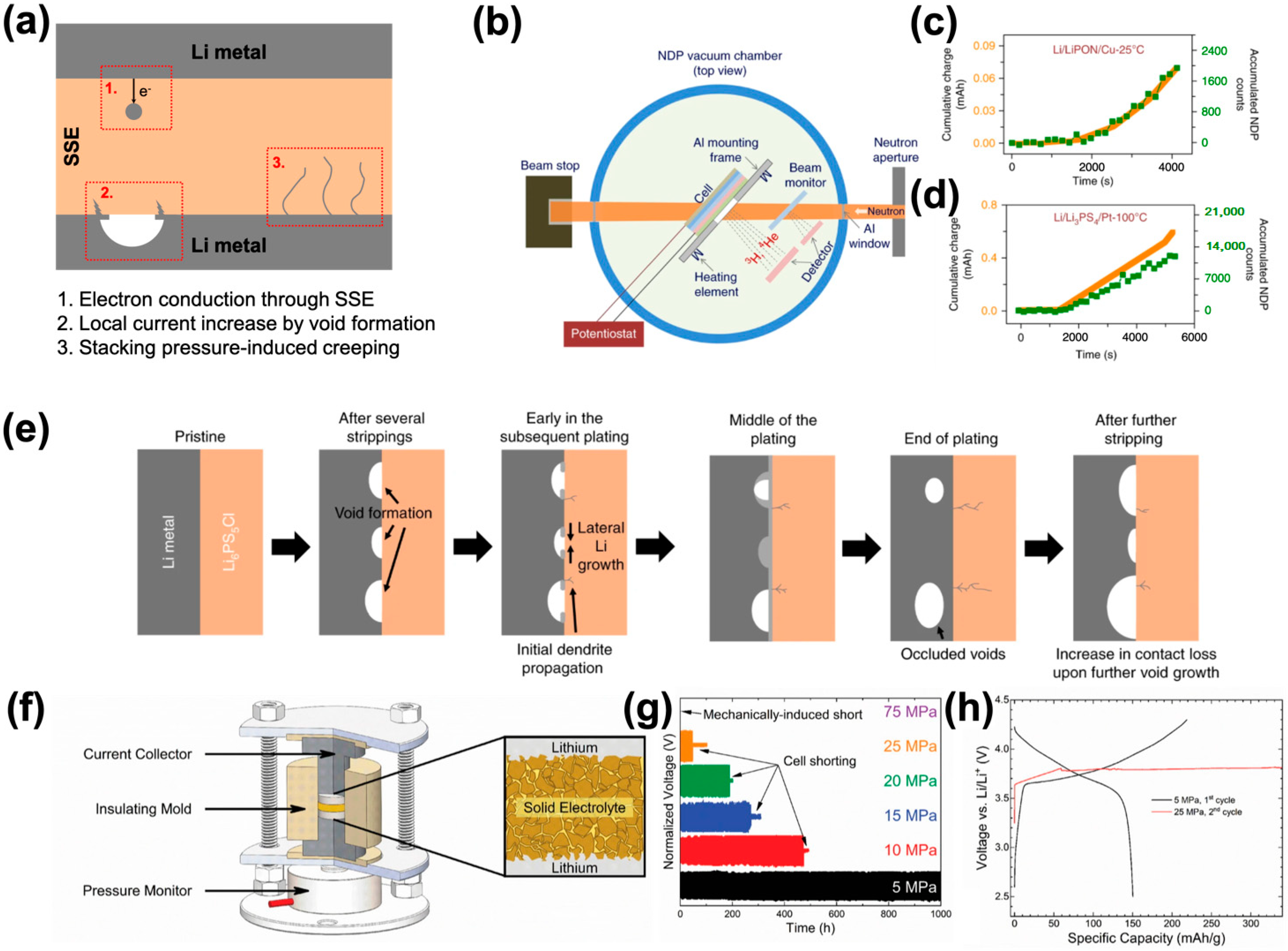
It is widely known that Li dendrite grows even in SSEs. However, it remains unclear how Li dendrite can penetrate through inorganic SSEs. Some plausible scenarios have been suggested (Figure 8a). First, Han et al. proposed that the relatively high electronic conductivity of SSEs is the origin of Li-dendrite formation within the electrolyte after monitoring the dynamic evolution of Li concentration profiles in SSEs during Li-metal plating using time-resolved operando neutron depth profiling (Figure 8b–d) [85]. They quantified the net amount of Li transported and compared it with the cumulative electric charge (Figure 8c,d). In the LiPON system, they did not observe a noticeable difference between the total amount of Li transported and the cumulative charge (Figure 8c). In contrast, a smaller amount of accumulated Li is observed than the cumulative charge in the Li3PS4 system (Figure 8d). Thus, they suggested that the Li dendrites are formed in the deep and undetectable region of the SSEs. Similar behavior is also observed in the LLZO electrolyte system. Given that the electronic conductivities of LLZO (10−9 S cm−1) and Li3PS4 (10−8 S cm−1) are much higher than that of LiPON (10−15–10−12 S cm−1) [86,87,88], they concluded that the relatively high electronic conductivity results in the Li dendrite formation. Second, in a recent work by Bruce’s group, it was proposed that voids formed during stripping increase the ‘effective’ current significantly because of the poor contact between Li metal and SSEs, thereby resulting in the dendritic formation upon plating in the Li6PS5Cl electrolyte system [89]. Figure 8e summarizes the proposed mechanism of Li-dendrite formation. The authors claimed that the high stacking pressure of the ASSBs can overcome the Li-dendrite growth issue: the Li-symmetric cell with 7 MPa did not show a noticeable polarization increase during 100 cycles at 1.0 mA cm−2, whereas the cell with 3 MPa showed a substantial increase of polarization during stripping and short circuit after 8 cycles at the same current density. A high stacking pressure forms more uniform interface between a SSE and Li metal, thereby increases contact areas. Thus, higher current density is needed to make Li dendrite penetration through the SSE at high stacking pressures. In a very recent computational work, void formation in Li metal during stripping was shown to depend on the lithiophilicity of the interface [90]. For example, Li2O and LiPON have lithiophilic interfaces with Li metal and do not show accumulated voids at the interface during the striping process in their density functional theory (DFT) and kinetic Monte Carlo (KMC) computations. In contrast, LiF with lithiophobicity shows accumulated void formation at the LiF/Li interface. This finding suggests that interface and coating design play important roles in suppressing Li dendrite growth. Third, it was proposed that the relatively high stacking pressure in ASSBs accelerates Li penetration through the SSEs [91,92,93]. Although some degree of stack pressure is required to ensure contact between an SSE and Li-metal anode [94], too high of a stack pressure results in Li dendrite penetration through the SSE and thus a short circuit. Recently, Meng’s group investigated the effect of stack pressure of ASSBs on the short-circuit behavior using the pressure-monitoring system shown in Figure 8f [91]. They observed the charge/discharge profiles of Li/Li6PS5Cl/Li symmetric cells at 75 µA cm−2 with different stack pressures from 5 to 75 MPa (Figure 8g). Interestingly, the cell with a very high stack pressure of 75 MPa showed a short circuit even before the Li plating and stripping test was conducted. The authors claimed that the short circuit at such high stack pressure is due to the creeping of Li metal to flow within the pores of Li6PS5Cl. When the stack pressure was lowered, the cell ran longer before the short circuit occurs. For example, for the cell with a stack pressure of 5 MPa, a short circuit was not observed within 1000 h of plating and stripping. In a full-cell configuration, the cell with a stack pressure of 5 MPa showed no short-circuit behavior and a typical charge–discharge profile, delivering a specific capacity of 150 mAh g−1 (Figure 8h). In contrast, the cell was short-circuited when the pressure was increased to 25 MPa. Large low-density structures were also observed in the SSE using X-ray tomography after the electrochemical Li plating and stripping process at 20 MPa. It was speculated that these low-density structures are Li dendrites and SEI formed between Li metal and Li6PS5Cl. Based on their observations, it is clear that the stack pressure is an important parameter to control Li plating and stripping behavior in ASSB systems; this idea is also supported by a recent work by Hänsel et al. [93]. In their work, they investigated the effect of the thickness of Li6PS5Cl at no current condition and observed that the time required for short circuit monotonically increases with the thickness of the Li6PS5Cl SSE. This finding demonstrates that the short circuit at high stack pressure occurs via Li extrusion through the micropores of SSEs. The same group also discovered that the characteristics of SEI affect Li and Na exclusion, and thus short-circuit behaviors, considerably [92]. In their comparison study, they showed very sharp contrast between Li3PS4/Li and Na3PS4/Na systems: Li3PS4 showed short circuit at 45 MPa after 55 h, whereas Na3PS4 did not show such behavior at the same stack pressure even after 250 h. The authors claimed that the root cause of these contrasting observations is the different characteristics of the SEI formed between Li3PS4 and Li metal vs. Na3PS4 and Na metal. Whereas the Li3PS4/Li system forms a very thin passivating layer, the SEI continues to grow at the Na3PS4/Na interface because of the relatively high electronic conductivity of Na3P and Na2S compared to that of their Li counterparts, confirmed by the density of states (DOS) computations. These results indicate that the thickness and mechanical properties of the SEI formed between an SSE and Li-metal anode are crucial parameters to enable the realization of Li-metal ASSBs.
3.3. Interface with Cathodes
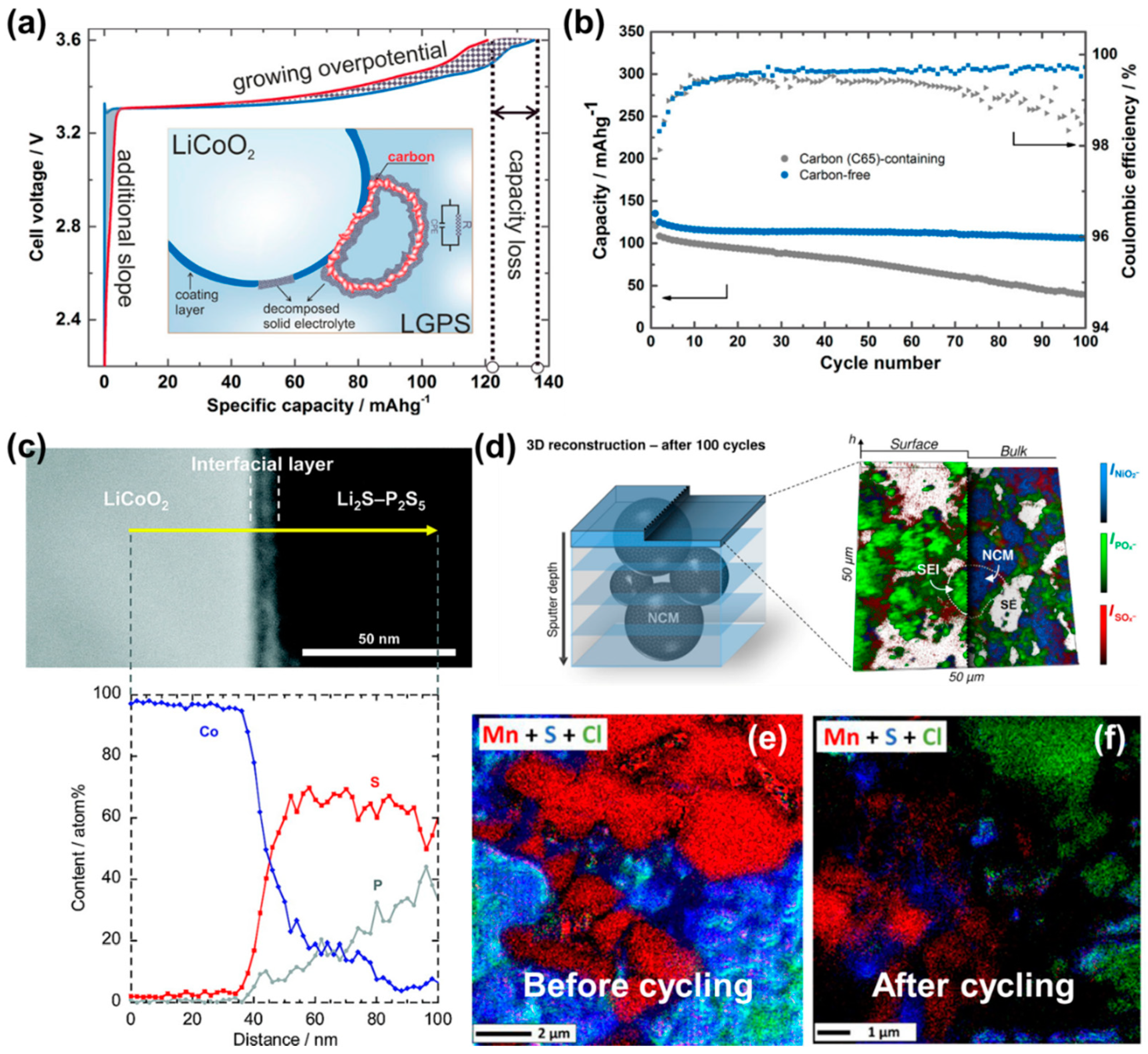
The cathode side has complicated interfaces since it contains various components to provide both electron and ion-conduction pathways. Typically, the cathode composite consists of a cathode active material, electron-conducting carbon, and an ion-conducting SSE. Therefore, it forms three distinct interfaces, cathode/carbon, cathode/SSE, and carbon/SSE (as shown in Figure 3). At the early stage of sulfide SSE development, sulfide SSEs were thought to be stable upon electrochemical oxidation [17,28,47]. However, recent works have shown that most of the sulfide SSEs are prone to instability during oxidation when electron pathways are provided [48,49,95,96,97,98]. Specifically, Zhang et al. investigated the interfacial properties of a carbon-containing cathode composite with a LGPS SSE [96]. Figure 9a presents a schematic illustration showing how the electron-conducting carbon additives affect the electrochemical reaction processes at the LiCoO2/LGPS interface. They found that the carbon additive contributes to an additional slope during the charging process and degrades the LGPS electrolyte, which increases the overpotential and thus decreases the specific capacity. In their ex situ XPS characterizations, it was confirmed that the LiCoO2/LGPS cathode composite with carbon additive shows much more pronounced decomposition of LGPS and produces more insulating sulfide products than the composite without carbon after 100 cycles. In addition, as shown in Figure 9b, the cathode composite without carbon additive exhibits better cycling stability after 100 cycles at 115 µA cm−2 (0.1C). Yoon et al. also demonstrated similar degradation mechanisms at the interface between LGPS and carbon [95]. Both groups observed that the degradation of the LGPS/carbon interface does not depend on the structure and morphology of the carbon additives. It is a great challenge because the sulfide SSE will decompose once electron pathways are provided, which is essential to enable ASSBs. However, we expect that it is possible to slow down such degradations by using a low carbon content or low surface area of carbon.
Chemical and electrochemical degradation of sulfide SSEs at the interface with the cathode material is another important hurdle to overcome. Sakuda et al. observed the interfacial layer between a LiCoO2 cathode and Li2S–P2S5 sulfide-SSE after the first charging using TEM and EDS, as shown in Figure 9c [99]. The authors reported the mutual diffusions of Co, P, and S at the interface between the LiCoO2 cathode and sulfide SSE. The formation of the interfacial layer increases the resistance of the cell significantly. In contrast, the authors were able to suppress the mutual diffusion and the formation of the interfacial layer by coating a Li2SiO3 thin film on the LiCoO2 cathode particle, thereby improving the specific capacity. Similarly, the diffusion of S, P, and Cl into LiNi0.8Co0.1Mn0.1O2 cathode particle was confirmed by the SEM/EDS technique [100]. Later, Walther et al. further studied the degradation mechanisms of the cathode composite of Li6PS5Cl/LiNi0.6Co0.2Mn0.2O2 [101]. They characterized the interphase formation using XPS combined with time-of-flight secondary-ion mass spectrometry (ToF-SIMS) to determine the composition and microstructure of interphases. Phosphate and sulfate compounds were detected by their ex situ XPS analysis after 100 cycles, which agrees with a report by Visbal et al. [102,103]. ToF-SIMS obtains compositional and morphological information on the interphases beyond the capability of XPS. To investigate the spatial fragment distribution, the depth profiles were reconstructed, as shown in Figure 9d. The results show that the intensities of the phosphates and sulfates are dominated by the interface regions, demonstrating the formation of the SEI with POx and SOx enriched. In the investigation of the interphase formation between the Li6PS5Cl SSE and LiMn2O4 cathode by Auvergniot et al., it was observed that the Li6PS5Cl electrolyte decomposes upon electrochemical cycling by scanning Auger microscopy (SAM) analysis. Figure 9e and f present the SAM mapping results before and after cycling, respectively. Before the electrochemical cycling, the S and Cl signals overlapped. However, the S-rich and Cl-rich regions are clearly separated after 22 cycles. The authors also observed such SSE decomposition and SEI formation in other oxide cathode systems, including LiCoO2 and LiNi1/3Co1/3Mn1/3O2 [103].
A recent study by Li’s group presented interesting experimental results that the oxidation stability of a sulfide SSE, LGPS, can be improved significantly and that the oxidation stability window can be expanded up to 10 V vs. Li metal by high mechanical stack pressure even if conductive carbon (10 wt%) is added [104]. The authors claimed that the high mechanical constriction can kinetically stabilize sulfide SSEs based on their DFT computations and experimental observations. Note that the authors used graphite-film-covered Li metal to avoid Li metal penetration through the LGPS electrolyte at high stack pressure. They presented good cycling stability: 91% retention after 360 cycles in LiCoO2/LGPS/Li4Ti5O12 and 82% retention after 100 cycles in LiNi0.5Mn1.5O4/LGPS/Li4Ti5O12 full-cell configurations. In ex situ XPS characterizations, no significant decomposition reactions of LGPS were observed. The effects of mechanical constriction on the electrochemical stability window of sulfide SSEs are well summarized in a recent review article [105]. However, it is questionable if such a high stack pressure (>250 MPa) of the cell is practically feasible and how much the cost of manufacturing ASSBs would increase.
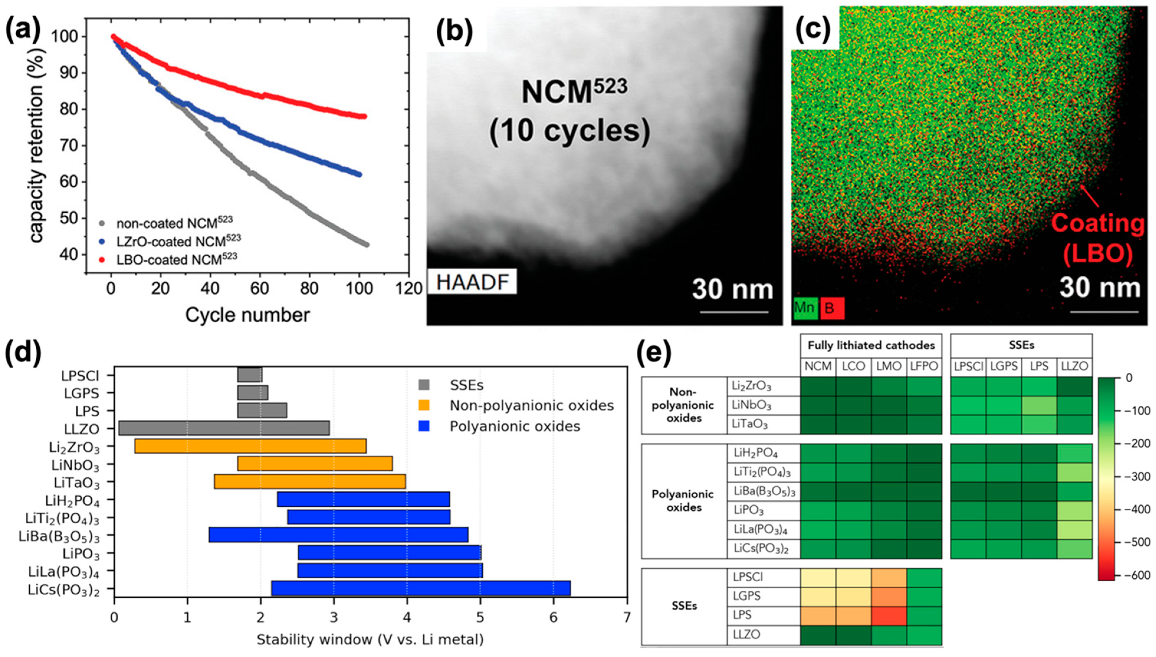
A representative strategy to avoid (electro)chemical degradation of the interface between a cathode and a sulfide SSE is the ‘cathode coating’ approach. Many ternary-metal oxide compounds have been studied for use as cathode coatings, including LiNbO3, LiTaO3, Li4Ti5O12, Li2SiO3, LiAlO2, Li2CoTi3O8, and Li2ZrO3 [24,56,99,106,107,108,109,110,111,112,113,114]. In theory, cathode coatings can separate an SSE from the low Li chemical potentials of the cathode in its highly charged state and prevent electrochemical self-decomposition of the SSE. However, such oxide coating compounds could not solve the interfacial issue between the cathode and sulfide SSE completely. In many cases, S/O exchange between coating materials and sulfide SSEs occurs, driven by the strong binding energy of PO4 groups, as confirmed by computational studies [51,115]. Recently, Zhang et al. observed a sharp contrast between two coating materials, Li2ZrO3 and Li3B11O18 [116]. They show that Li extraction occurs at Li2ZrO3 during the first charge process and that it loses its protection capability for the cathode. It was also observed that metal sulfides form within the Li2ZrO3 coating after 50 cycles. Therefore, it presents ~60% capacity retention after 100 cycles (Figure 10a). In contrast, Li3B11O18 coating material shows much improved cycling stability, ~80% retention after 100 cycles. The Li3B11O18 coating is also confirmed to be well maintained even after 10 cycles using STEM, as shown in Figure 10b,c.
Yihan et al. conducted a computational investigation to identify Li-containing cathode coating materials [115]. In their work, the phase stability, electrochemical and chemical stability against both cathodes and SSEs, and ionic conductivity were considered. The computational screening identifies polyanionic oxide compounds as promising cathode coating materials, including phosphates and borates. Figure 10d shows the electrochemical stability windows of six polyanionic oxides selected by Yihan et al. For better comparison, they plotted the electrochemical stability windows of common sulfide SSEs: Li6PS5Cl (LPSCl), LGPS, the glass-ceramic LPS, garnet-type LLZO, and ternary non-polyanionic coating materials such as Li2ZrO3, LiNbO3, and LiTaO3. Polyanionic oxides have much higher oxidation stability (>4.5 V) than non-polyanionic oxides (3–4 V). They explained that the higher oxidation limit of polyanionic oxides is attributable to the highly covalent bonds between M (here, P and B) and oxygen in MOx polyhedral units, which lowers the energy of the oxygen orbitals. This effect decreases the chemical reactivity of the polyanionic compounds with sulfide SSEs and increases the oxidation stability limit significantly. They also computed the reaction energy between each component, including the sulfide SSEs, oxide cathodes, and coating materials, as presented in Figure 10e. As expected, sulfide SSEs show very high reactivity with most of the oxide cathode materials. Interestingly, the reactivity between an oxide coating and a sulfide SSE is similar with that between an oxide cathode and a sulfide SSE (>100 meV/atom). In contrast, the polyanionic coating materials show less reactivity against sulfide SSEs. Similarly, Liu et al. explored the fluorides for cathode coatings using high-throughput computational screening [117]. By screening the phase stability, electrochemical stability, chemical stability, and Li-ion conductivity, they identified Li2MF6 (M = Si, Ge, Zr, Ti) compounds as good coating materials. However, their work did not aim for ASSB applications; thus, they did not include the chemical reactivity between SSEs and coating materials, which merit investigation.
4. Perspectives and Outlooks
The promise of ASSBs arises from the high safety and use of energy-dense Li-metal anodes. At a very early stage, it was expected that ‘hard’ and ‘non-flammable’ SSEs could prevent the dendritic growth of ‘soft’ Li metals. However, many studies have since demonstrated that Li metals can still penetrate SSEs at relatively high current rates [52,55,118,119]. One simple way to suppress Li dendrite growth is to ensure good contact between the SSE and electrode in order to increase the effective contact area, thereby reducing the effective current. Relatively high stacking pressure can ensure contact between the Li metal and SSE and suppress Li dendrite growth, as demonstrated by Bruce’s group [89]. However, too high of a stacking pressure can lead to Li extrusion and thereby Li dendrite penetration through the micropores of the SSE [91,93]. Another strategy is to form a lithiophilic interphase that ensures contact between the Li metal and SSE [90]. This strategy has been widely studied with some successes shown not only in sulfide but also in oxide SSEs [120,121,122,123]. However, it is vital to better understand Li-dendrite growth mechanisms. Although there are some plausible explanations, as discussed in Section 3.2, the mechanism is not yet fully understood. We do not expect that a single theory can explain everything but suspect that instead the origin of Li-dendrite formation could depend on the properties of SSEs.
There have been significant efforts to understand SEI formation on both cathodes and anodes since the chemical evolution of SEI plays a critical role in determining the electrochemical properties of ASSBs [71,72,74,99,101,103]. However, our current understanding is still limited, including with respect to the thickness of the interphases and the nature of their microstructures. This lack of knowledge can be mainly attributed to the buried nature inside the solid-state bulk cell, which is thus not readily accessible using most conventional analysis techniques. Further, the extreme reactivity of the Li metal, sulfide SSE, and interphases to moisture, oxygen, and even the electron beam are other important challenges for their characterization. Such high reactivity requires air-tight sample preparation and transfer capabilities for studying buried interfaces since typical sample handling can damage these highly reactive materials. In addition, due to vulnerability to the e-beam, the sample can be damaged during the electron microscopy analyses. Thus, most previous works have been limited to low magnification to minimize the electron-beam dose rate to the sample. However, owing to recent developments of electron microscopy technology, such as a multi-capable TEM sample holders (e.g., offering both cryo and air-tight transfer capabilities in a single holder), high-sensitive electron detectors, etc., it is expected to play a major role soon in investigations of the morphological/structural/chemical properties of the interphase.
Although several works have proposed coating materials that can stabilize the interface between the SSE and cathode active materials [115,116,117], another critical issue remains, namely the oxidation of the SSE at the interfaces with the conductive additive (e.g., carbon) and current collector (since an SSE is subject to the full cathode potential at such interfaces). Using a low carbon additive content would reduce such oxidation of the SSE. However, a better strategy is required. One alternative could be a dual coating method that uses carbon nanowire or nano-mesh with uniform cathode active material coating and then SSE coating. This structure will be able to separate electron and ion pathways. Another strategy is to form a passivating interface between a sulfide SSE and carbon.
5. Summary
Sulfide SSEs have attracted significant interest as a key component to realize ASSBs due to their high ionic conductivity and deformability. However, there are remaining challenges. Herein, we provided an overview of the major challenges in interfaces and interphases formed in sulfide SSE systems and the recent progress that has been made in understanding such interface and interphase formation. Then, efforts to address interface and interphase issues in sulfide SSEs were introduced, including several strategies to stabilize the interface or form passivating interphase. Finally, we provided our perspectives on future research directions, with the hope that this review will help guide potential efforts for developing long-lasting and fast-charging solid-state batteries.
Author Contributions
Writing, Y.-W.B. and H.K.; Visualization, Y.-W.B.; Supervision, H.K. Both authors have read and agreed to the published version of the manuscript.
Funding
This work was supported by the Laboratory Directed Research and Development Program of Lawrence Berkeley National Laboratory under U.S. Department of Energy Contract No. DE-AC02-05CH11231.
Institutional Review Board Statement
Not applicable.
Informed Consent Statement
Not applicable.
Data Availability Statement
The data presented in this study are available on request from the corresponding author.
Conflicts of Interest
The authors declare no conflict of interest.
References
- Whittingham, M.S. Electrical Energy Storage and Intercalation Chemistry. Science 1976, 192, 1126–1127. [Google Scholar] [CrossRef]
- Nagaura, T. A lithium ion battery. In Proceedings of the 5th International Seminar on Lithium Battery Technology and Applications, Deerfield Beach, FL, USA, 5–7 March 1990. [Google Scholar]
- Xu, K. Nonaqueous Liquid Electrolytes for Lithium-Based Rechargeable Batteries. Chem. Rev. 2004, 104, 4303–4418. [Google Scholar] [CrossRef] [PubMed]
- Bruce, P.G. Energy storage beyond the horizon: Rechargeable lithium batteries. Solid State Ion. 2008, 179, 752–760. [Google Scholar] [CrossRef]
- Thackeray, M.M.; Wolverton, C.; Isaacs, E.D. Electrical energy storage for transportation—approaching the limits of, and going beyond, lithium-ion batteries. Energy Environ. Sci. 2012, 5, 7854. [Google Scholar] [CrossRef]
- U.S. DRIVE. Electrochemical Energy Storage Technical Team Roadmap; US Department of Energy: Washington, DC, USA, 2013.
- Li, C.; Negnevitsky, M.; Wang, X.; Yue, W.L.; Zou, X. Multi-criteria analysis of policies for implementing clean energy vehicles in China. Energy Policy 2019, 129, 826–840. [Google Scholar] [CrossRef]
- Takehiko, N. The Japanese Policy and NEDO Activity for Future Mobility; Representative office in Europe, New Energy and Industrial Technology Development Organization (NEDO): Paris, France, 2017. [Google Scholar]
- Harris, S.J. Unlocking a Secret Stash of Energy. Joule 2020, 4, 1155–1157. [Google Scholar] [CrossRef]
- Xiao, Y.; Wang, Y.; Bo, S.-H.; Kim, J.C.; Miara, L.J.; Ceder, G. Understanding interface stability in solid-state batteries. Nat. Rev. Mater. 2020, 5, 105–126. [Google Scholar] [CrossRef]
- Tian, Y.; Zeng, G.; Rutt, A.; Shi, T.; Kim, H.; Wang, J.; Koettgen, J.; Sun, Y.; Ouyang, B.; Chen, T.; et al. Promises and Challenges of Next-Generation “Beyond Li-ion” Batteries for Electric Vehicles and Grid Decarbonization. Chem. Rev. 2021, 121, 1623–1669. [Google Scholar] [CrossRef]
- Appetecchi, G.B.; Shin, J.H.; Alessandrini, F.; Passerini, S. 0.6Ah Li/V2O5 battery prototypes based on solvent-free PEO–LiN(SO2CF2CF3)2 polymer electrolytes. J. Power Sources 2005, 143, 236–242. [Google Scholar] [CrossRef]
- Seino, Y.; Takada, K.; Kim, B.-C.; Zhang, L.; Ohta, N.; Wada, H.; Osada, M.; Sasaki, T. Synthesis of phosphorous sulfide solid electrolyte and all-solid-state lithium batteries with graphite electrode. Solid State Ion. 2005, 176, 2389–2393. [Google Scholar] [CrossRef]
- Monroe, C.; Newman, J. The impact of elastic deformation on deposition kinetics at lithium/polymer interfaces. J. Electrochem. Soc. 2005, 152, A396–A404. [Google Scholar] [CrossRef]
- Baba, M.; Kumagai, N.; Fujita, H.; Ohta, K.; Nishidate, K.; Komaba, S.; Kaplan, B.; Groult, H.; Devilliers, D. Multi-layered Li-ion rechargeable batteries for a high-voltage and high-current solid-state power source. J. Power Sources 2003, 119, 914–917. [Google Scholar] [CrossRef]
- Sato, T.; Morinaga, T.; Marukane, S.; Narutomi, T.; Igarashi, T.; Kawano, Y.; Ohno, K.; Fukuda, T.; Tsujii, Y. Novel Solid-State Polymer Electrolyte of Colloidal Crystal Decorated with Ionic-Liquid Polymer Brush. Adv. Mater. 2011, 23, 4868–4872. [Google Scholar] [CrossRef]
- Kamaya, N.; Homma, K.; Yamakawa, Y.; Hirayama, M.; Kanno, R.; Yonemura, M.; Kamiyama, T.; Kato, Y.; Hama, S.; Kawamoto, K.; et al. A lithium superionic conductor. Nat. Mater. 2011, 10, 682–686. [Google Scholar] [CrossRef] [PubMed]
- Tatsumisago, M.; Nagao, M.; Hayashi, A. Recent development of sulfide solid electrolytes and interfacial modification for all-solid-state rechargeable lithium batteries. J. Asian Ceram. Soc. 2013, 1, 17–25. [Google Scholar] [CrossRef] [Green Version]
- Richards, W.D.; Miara, L.J.; Wang, Y.; Kim, J.C.; Ceder, G. Interface Stability in Solid-State Batteries. Chem. Mater. 2016, 28, 266–273. [Google Scholar] [CrossRef]
- Ma, Z.; Xue, H.-G.; Guo, S.-P. Recent achievements on sulfide-type solid electrolytes: Crystal structures and electrochemical performance. J. Mater. Sci. 2018, 53, 3927–3938. [Google Scholar] [CrossRef]
- Chen, S.; Xie, D.; Liu, G.; Mwizerwa, J.P.; Zhang, Q.; Zhao, Y.; Xu, X.; Yao, X. Sulfide Solid Electrolytes for All-Solid-State Lithium Batteries: Structure, Conductivity, Stability and Application. Energy Storage Mater. 2018, 14, 58–74. [Google Scholar] [CrossRef]
- Reddy, M.V.; Julien, C.M.; Mauger, A.; Zaghib, K. Sulfide and Oxide Inorganic Solid Electrolytes for All-Solid-State Li Batteries: A Review. Nanomaterials 2020, 10, 1606. [Google Scholar] [CrossRef] [PubMed]
- Kudu, Ö.U.; Famprikis, T.; Fleutot, B.; Braida, M.-D.; Mercier, T.L.; Islam, M.S.; Masquelier, C. A review of structural properties and synthesis methods of solid electrolyte materials in the Li2S−P2S5 binary system. J. Power Sources 2018, 407, 31–43. [Google Scholar] [CrossRef]
- Kato, Y.; Hori, S.; Saito, T.; Suzuki, K.; Hirayama, M.; Mitsui, A.; Yonemura, M.; Iba, H.; Kanno, R. High-power all-solid-state batteries using sulfide superionic conductors. Nat. Energy 2016, 1, 16030. [Google Scholar] [CrossRef]
- Kwon, O.; Hirayama, M.; Suzuki, K.; Kato, Y.; Saito, T.; Yonemura, M.; Kamiyama, T.; Kanno, R. Synthesis, structure, and conduction mechanism of the lithium superionic conductor Li10+δGe1+δP2−δS12. J. Mater. Chem. A 2014, 3, 438–446. [Google Scholar] [CrossRef]
- Sun, Y.; Suzuki, K.; Hori, S.; Hirayama, M.; Kanno, R. Superionic Conductors: Li10+δ[SnySi1−y]1+δP2−δS12 with a Li10GeP2S12-type Structure in the Li3PS4-Li4SnS4-Li4SiS4 Quasi-ternary System. Chem. Mater. 2017, 29, 5858–5864. [Google Scholar] [CrossRef]
- Hori, S.; Suzuki, K.; Hirayama, M.; Kato, Y.; Saito, T.; Yonemura, M.; Kanno, R. Synthesis, structure, and ionic conductivity of solid solution, Li10+δM1+δP2−δS12 (M = Si, Sn). Faraday Discuss. 2014, 176, 83–94. [Google Scholar] [CrossRef] [PubMed]
- Seino, Y.; Ota, T.; Takada, K.; Hayashi, A.; Tatsumisago, M. A sulphide lithium super ion conductor is superior to liquid ion conductors for use in rechargeable batteries. Energy Environ. Sci. 2013, 7, 627–631. [Google Scholar] [CrossRef]
- Mizuno, F.; Hayashi, A.; Tadanaga, K.; Tatsumisago, M. New, Highly Ion-Conductive Crystals Precipitated from Li2S–P2S5 Glasses. Adv. Mater. 2005, 17, 918–921. [Google Scholar] [CrossRef]
- Homann, G.; Meister, P.; Stolz, L.; Brinkmann, J.P.; Kulisch, J.; Adermann, T.; Winter, M.; Kasnatscheew, J. High-Voltage All-Solid-State Lithium Battery with Sulfide-Based Electrolyte: Challenges for the Construction of a Bipolar Multicell Stack and How to Overcome Them. ACS Appl. Energy Mater. 2020, 3, 3162–3168. [Google Scholar] [CrossRef]
- Minami, K.; Mizuno, F.; Hayashi, A.; Tatsumisago, M. Lithium ion conductivity of the Li2S–P2S5 glass-based electrolytes prepared by the melt quenching method. Solid State Ion. 2007, 178, 837–841. [Google Scholar] [CrossRef]
- Mizuno, F.; Ohtomo, T.; Hayashi, A.; Tadanaga, K.; Minami, T.; Tatsumisago, M. Structure and Ionic Conductivity of Li2S-P2S5-P2O5 Glasses and Glass-Ceramics Prepared by Mechanical Milling. J. Ceram. Soc. Jpn. Suppl. 2004, 112, S709–S712. [Google Scholar] [CrossRef]
- Tan, D.H.S.; Banerjee, A.; Deng, Z.; Wu, E.A.; Nguyen, H.; Doux, J.-M.; Wang, X.; Cheng, J.-h.; Ong, S.P.; Meng, Y.S.; et al. Enabling Thin and Flexible Solid-State Composite Electrolytes by the Scalable Solution Process. ACS Appl. Energy Mater. 2019, 2, 6542–6550. [Google Scholar] [CrossRef]
- Liu, Z.; Fu, W.; Payzant, E.A.; Yu, X.; Wu, Z.; Dudney, N.J.; Kiggans, J.; Hong, K.; Rondinone, A.J.; Liang, C. Anomalous High Ionic Conductivity of Nanoporous β-Li3PS4. J. Am. Chem. Soc. 2013, 135, 975–978. [Google Scholar] [CrossRef]
- Kennedy, J.H.; Zhang, Z.; Eckert, H. Ionically conductive sulfide-based lithium glasses. J. Non-Cryst. Solids 1990, 123, 328–338. [Google Scholar] [CrossRef]
- Wada, H.; Menetrier, M.; Levasseur, A.; Hagenmuller, P. Preparation and ionic conductivity of new B2S3-Li2S-LiI glasses. Mater. Res. Bull. 1983, 18, 189–193. [Google Scholar] [CrossRef]
- Yamauchi, A.; Sakuda, A.; Hayashi, A.; Tatsumisago, M. Preparation and ionic conductivities of (100 − x)(0.75Li2S·0.25P2S5)·xLiBH4 glass electrolytes. J. Power Sources 2013, 244, 707–710. [Google Scholar] [CrossRef]
- Dietrich, C.; Weber, D.A.; Sedlmaier, S.J.; Indris, S.; Culver, S.P.; Walter, D.; Janek, J.; Zeier, W.G. Lithium ion conductivity in Li2S–P2S5 glasses—Building units and local structure evolution during the crystallization of superionic conductors Li3PS4, Li7P3S11 and Li4P2S7. J. Mater. Chem. A 2017, 5, 18111–18119. [Google Scholar] [CrossRef]
- Hayashi, A.; Hama, S.; Minami, T.; Tatsumisago, M. Formation of superionic crystals from mechanically milled Li2S–P2S5 glasses. Electrochem. Commun. 2003, 5, 111–114. [Google Scholar] [CrossRef]
- Marple, M.A.T.; Aitken, B.G.; Kim, S.; Sen, S. Fast Li-Ion Dynamics in Stoichiometric Li2S–Ga2Se3–GeSe2 Glasses. Chem. Mater. 2017, 29, 8704–8710. [Google Scholar] [CrossRef]
- Ohno, S.; Bernges, T.; Buchheim, J.; Duchardt, M.; Hatz, A.-K.; Kraft, M.A.; Kwak, H.; Santhosha, A.L.; Liu, Z.; Minafra, N.; et al. How Certain Are the Reported Ionic Conductivities of Thiophosphate-Based Solid Electrolytes? An Interlaboratory Study. ACS Energy Lett. 2020, 5, 910–915. [Google Scholar] [CrossRef] [Green Version]
- Zhang, Z.; Zhang, L.; Liu, Y.; Yu, C.; Yan, X.; Xu, B.; Wang, L.-M. Synthesis and characterization of argyrodite solid electrolytes for all-solid-state Li-ion batteries. J. Alloy. Compd. 2018, 747, 227–235. [Google Scholar] [CrossRef] [Green Version]
- Zhang, Z.; Zhang, L.; Yan, X.; Wang, H.; Liu, Y.; Yu, C.; Cao, X.; Eijck, L.V.; Wen, B. All-in-one improvement toward Li6PS5Br-Based solid electrolytes triggered by compositional tune. J. Power Sources 2019, 410, 162–170. [Google Scholar] [CrossRef]
- Rangasamy, E.; Liu, Z.; Gobet, M.; Pilar, K.; Sahu, G.; Zhou, W.; Wu, H.; Greenbaum, S.; Liang, C. An iodide-based Li7P2S8I superionic conductor. J. Am. Chem. Soc. 2015, 137, 1384–1387. [Google Scholar] [CrossRef]
- Huang, W.; Yoshino, K.; Hori, S.; Suzuki, K.; Yonemura, M.; Hirayama, M.; Kanno, R. Superionic Lithium Conductor with a Cubic Argyrodite-type Structure in the Li–Al–Si–S system. J. Solid State Chem. 2018, 270, 487–492. [Google Scholar] [CrossRef]
- Stallworth, P.E.; Fontanella, J.J.; Wintersgill, M.C.; Scheidler, C.D.; Immel, J.J.; Greenbaum, S.G.; Gozdz, A.S. NMR, DSC and high pressure electrical conductivity studies of liquid and hybrid electrolytes. J. Power Sources 1999, 81, 739–747. [Google Scholar] [CrossRef]
- Kanno, R.; Murayama, M. Lithium Ionic Conductor Thio-LISICON: The Li2S-GeS2-P2S5 System. J. Electrochem. Soc. 2001, 148, A742. [Google Scholar] [CrossRef]
- Han, F.; Zhu, Y.; He, X.; Mo, Y.; Wang, C. Electrochemical Stability of Li10GeP2S12 and Li7La3Zr2O12 Solid Electrolytes. Adv. Energy Mater. 2016, 6, 1501590. [Google Scholar] [CrossRef]
- Dewald, G.F.; Ohno, S.; Kraft, M.A.; Koerver, R.; Till, P.; Vargas-Barbosa, N.M.; Janek, J.; Zeier, W.G. Experimental Assessment of the Practical Oxidative Stability of Lithium Thiophosphate Solid Electrolytes. Chem. Mater. 2019, 31, 8328–8337. [Google Scholar] [CrossRef]
- Zhu, Y.; He, X.; Mo, Y. Origin of Outstanding Stability in the Lithium Solid Electrolyte Materials: Insights from Thermodynamic Analyses Based on First-Principles Calculations. ACS Appl. Mater. Interfaces 2015, 7, 23685–23693. [Google Scholar] [CrossRef]
- Zhu, Y.; He, X.; Mo, Y. First principles study on electrochemical and chemical stability of solid electrolyte–electrode interfaces in all-solid-state Li-ion batteries. J. Mater. Chem. A 2016, 4, 3253–3266. [Google Scholar] [CrossRef]
- Porz, L.; Swamy, T.; Sheldon, B.W.; Rettenwander, D.; Frömling, T.; Thaman, H.L.; Berendts, S.; Uecker, R.; Carter, W.C.; Chiang, Y.-M. Mechanism of Lithium Metal Penetration through Inorganic Solid Electrolytes. Adv. Energy Mater. 2017, 7, 1701003. [Google Scholar] [CrossRef]
- Lewis, J.A.; Cortes, F.J.Q.; Boebinger, M.G.; Tippens, J.; Marchese, T.S.; Kondekar, N.; Liu, X.; Chi, M.; McDowell, M.T. Interphase Morphology between a Solid-State Electrolyte and Lithium Controls Cell Failure. ACS Energy Lett. 2019, 4, 591–599. [Google Scholar] [CrossRef]
- Kazyak, E.; Garcia-Mendez, R.; LePage, W.S.; Sharafi, A.; Davis, A.L.; Sanchez, A.J.; Chen, K.-H.; Haslam, C.; Sakamoto, J.; Dasgupta, N.P. Li Penetration in Ceramic Solid Electrolytes: Operando Microscopy Analysis of Morphology, Propagation, and Reversibility. Matter 2020, 2, 1025–1048. [Google Scholar] [CrossRef]
- Ji, X.; Hou, S.; Wang, P.; He, X.; Piao, N.; Chen, J.; Fan, X.; Wang, C. Solid-State Electrolyte Design for Lithium Dendrite Suppression. Adv. Mater. 2020, 32, 2002741. [Google Scholar] [CrossRef]
- Takada, K.; Ohta, N.; Zhang, L.; Fukuda, K.; Sakaguchi, I.; Ma, R.; Osada, M.; Sasaki, T. Interfacial modification for high-power solid-state lithium batteries. Solid State Ion. 2008, 179, 1333–1337. [Google Scholar] [CrossRef]
- Nagao, M.; Hayashi, A.; Tatsumisago, M. Fabrication of favorable interface between sulfide solid electrolyte and Li metal electrode for bulk-type solid-state Li/S battery. Electrochem. Commun. 2012, 22, 177–180. [Google Scholar] [CrossRef]
- Huang, B.; Yao, X.; Huang, Z.; Guan, Y.; Jin, Y.; Xu, X. Li3PO4-doped Li7P3S11 glass-ceramic electrolytes with enhanced lithium ion conductivities and application in all-solid-state batteries. J. Power Sources 2015, 284, 206–211. [Google Scholar] [CrossRef]
- Yu, C.; Ganapathy, S.; Klerk, N.J.J.d.; Roslon, I.; Eck, E.R.H.v.; Kentgens, A.P.M.; Wagemaker, M. Unravelling Li-Ion Transport from Picoseconds to Seconds: Bulk versus Interfaces in an Argyrodite Li6PS5Cl–Li2S All-Solid-State Li-Ion Battery. J. Am. Chem. Soc. 2016, 138, 11192–11201. [Google Scholar] [CrossRef] [PubMed]
- Sakuma, M.; Suzuki, K.; Hirayama, M.; Kanno, R. Reactions at the electrode/electrolyte interface of all-solid-state lithium batteries incorporating Li–M (M = Sn, Si) alloy electrodes and sulfide-based solid electrolytes. Solid State Ion. 2016, 285, 101–105. [Google Scholar] [CrossRef]
- Bachman, J.C.; Muy, S.; Grimaud, A.; Chang, H.-H.; Pour, N.; Lux, S.F.; Paschos, O.; Maglia, F.; Lupart, S.; Lamp, P.; et al. Inorganic Solid-State Electrolytes for Lithium Batteries: Mechanisms and Properties Governing Ion Conduction. Chem. Rev. 2016, 116, 140–162. [Google Scholar] [CrossRef]
- Hayashi, A.; Sakuda, A.; Tatsumisago, M. Development of Sulfide Solid Electrolytes and Interface Formation Processes for Bulk-Type All-Solid-State Li and Na Batteries. Front. Energy Res. 2016, 4, 25. [Google Scholar] [CrossRef] [Green Version]
- Auvergniot, J.; Cassel, A.; Foix, D.; Viallet, V.; Seznec, V.; Dedryvère, R. Redox activity of argyrodite Li6PS5Cl electrolyte in all-solid-state Li-ion battery: An XPS study. Solid State Ion. 2017, 300, 78–85. [Google Scholar] [CrossRef]
- Ito, Y.; Otoyama, M.; Hayashi, A.; Ohtomo, T.; Tatsumisago, M. Electrochemical and structural evaluation for bulk-type all-solid-state batteries using Li4GeS4-Li3PS4 electrolyte coating on LiCoO2 particles. J. Power Sources 2017, 360, 328–335. [Google Scholar] [CrossRef]
- Yu, C.; Ganapathy, S.; Eck, E.R.H.v.; Wang, H.; Basak, S.; Li, Z.; Wagemaker, M. Accessing the bottleneck in all-solid state batteries, lithium-ion transport over the solid-electrolyte-electrode interface. Nat. Commun. 2017, 8, 1086. [Google Scholar] [CrossRef]
- Kato, A.; Kowada, H.; Deguchi, M.; Hotehama, C.; Hayashi, A.; Tatsumisago, M. XPS and SEM analysis between Li/Li3PS4 interface with Au thin film for all-solid-state lithium batteries. Solid State Ion. 2018, 322, 1–4. [Google Scholar] [CrossRef]
- Chen, B.; Xu, C.; Wang, H.; Zhou, J. Insights into interfacial stability of Li6PS5Cl solid electrolytes with buffer layers. Curr. Appl. Phys. 2018, 19, 149–154. [Google Scholar] [CrossRef]
- Wenzel, S.; Leichtweiss, T.; Krüger, D.; Sann, J.; Janek, J. Interphase formation on lithium solid electrolytes—An in situ approach to study interfacial reactions by photoelectron spectroscopy. Solid State Ion. 2015, 278, 98–105. [Google Scholar] [CrossRef]
- Wenzel, S.; Leichtweiss, T.; Weber, D.A.; Sann, J.; Zeier, W.G.; Janek, J. Interfacial Reactivity Benchmarking of the Sodium Ion Conductors Na3PS4 and Sodium β-Alumina for Protected Sodium Metal Anodes and Sodium All-Solid-State Batteries. ACS Appl. Mater. Interfaces 2016, 8, 28216–28224. [Google Scholar] [CrossRef]
- Wenzel, S.; Weber, D.A.; Leichtweiss, T.; Busche, M.R.; Sann, J.; Janek, J. Interphase formation and degradation of charge transfer kinetics between a lithium metal anode and highly crystalline Li7P3S11 solid electrolyte. Solid State Ion. 2016, 286, 24–33. [Google Scholar] [CrossRef]
- Wenzel, S.; Sedlmaier, S.J.; Dietrich, C.; Zeier, W.G.; Janek, J. Interfacial reactivity and interphase growth of argyrodite solid electrolytes at lithium metal electrodes. Solid State Ion. 2018, 318, 102–112. [Google Scholar] [CrossRef]
- Wenzel, S.; Randau, S.; Leichtweiß, T.; Weber, D.A.; Sann, J.; Zeier, W.G.; Janek, J.r. Direct Observation of the Interfacial Instability of the Fast Ionic Conductor Li10GeP2S12 at the Lithium Metal Anode. Chem. Mater. 2016, 28, 2400–2407. [Google Scholar] [CrossRef]
- Cheng, T.; Merinov, B.V.; Morozov, S.; Goddard, W.A. Quantum Mechanics Reactive Dynamics Study of Solid Li-Electrode/Li6PS5Cl-Electrolyte Interface. ACS Energy Lett. 2017, 2, 1454–1459. [Google Scholar] [CrossRef] [Green Version]
- Wood, K.N.; Steirer, K.X.; Hafner, S.E.; Ban, C.; Santhanagopalan, S.; Lee, S.-H.; Teeter, G. Operando X-ray photoelectron spectroscopy of solid electrolyte interphase formation and evolution in Li2S-P2S5 solid-state electrolytes. Nat. Commun. 2018, 9, 2490. [Google Scholar] [CrossRef] [PubMed]
- Wang, C.; Zhao, Y.; Sun, Q.; Li, X.; Liu, Y.; Liang, J.; Li, X.; Lin, X.; Li, R.; Adair, K.R.; et al. Stabilizing interface between Li10SnP2S12 and Li metal by molecular layer deposition. Nano Energy 2018, 53, 168–174. [Google Scholar] [CrossRef]
- Ye, L.; Li, X. A dynamic stability design strategy for lithium metal solid state batteries. Nature 2021, 593, 218–222. [Google Scholar] [CrossRef] [PubMed]
- Yang, Y.; Han, J.; DeVita, M.; Lee, S.S.; Kim, J.C. Lithium and Chlorine-Rich Preparation of Mechanochemically Activated Antiperovskite Composites for Solid-State Batteries. Front. Chem. 2020, 8, 562549. [Google Scholar] [CrossRef]
- Han, F.; Yue, J.; Zhu, X.; Wang, C. Suppressing Li Dendrite Formation in Li2S-P2S5 Solid Electrolyte by LiI Incorporation. Adv. Energy Mater. 2018, 8, 1703644. [Google Scholar] [CrossRef]
- Garcia-Mendez, R.; Mizuno, F.; Zhang, R.; Arthur, T.S.; Sakamoto, J. Effect of Processing Conditions of 75Li2S-25P2S5 Solid Electrolyte on its DC Electrochemical Behavior. Electrochim. Acta 2017, 237, 144–151. [Google Scholar] [CrossRef]
- Liu, G.; Weng, W.; Zhang, Z.; Wu, L.; Yang, J.; Yao, X. Densified Li6PS5Cl Nanorods with High Ionic Conductivity and Improved Critical Current Density for All-Solid-State Lithium Batteries. Nano Lett. 2020, 20, 6660–6665. [Google Scholar] [CrossRef]
- Lee, Y.; Jeong, J.; Lim, H.-D.; Kim, S.-O.; Jung, H.-G.; Chung, K.Y.; Yu, S. Superionic Si-Substituted Lithium Argyrodite Sulfide Electrolyte Li6+xSb1–xSixS5I for All-Solid-State Batteries. ACS Sustain. Chem. Eng. 2021, 9, 120–128. [Google Scholar] [CrossRef]
- Qian, J.; Henderson, W.A.; Xu, W.; Bhattacharya, P.; Engelhard, M.; Borodin, O.; Zhang, J.-G. High rate and stable cycling of lithium metal anode. Nat. Commun. 2015, 6, 6362. [Google Scholar] [CrossRef] [Green Version]
- Otoyama, M.; Suyama, M.; Hotehama, C.; Kowada, H.; Takeda, Y.; Ito, K.; Sakuda, A.; Tatsumisago, M.; Hayashi, A. Visualization and Control of Chemically Induced Crack Formation in All-Solid-State Lithium-Metal Batteries with Sulfide Electrolyte. ACS Appl. Mater. Interfaces 2021, 13, 5000–5007. [Google Scholar] [CrossRef]
- Ning, Z.; Jolly, D.S.; Li, G.; De Meyere, R.; Pu, S.D.; Chen, Y.; Kasemchainan, J.; Ihli, J.; Gong, C.; Liu, B.; et al. Visualizing plating-induced cracking in lithium-anode solid-electrolyte cells. Nat. Mater. 2021, 322, 1–4. [Google Scholar] [CrossRef]
- Han, F.; Westover, A.S.; Yue, J.; Fan, X.; Wang, F.; Chi, M.; Leonard, D.N.; Dudney, N.J.; Wang, H.; Wang, C. High electronic conductivity as the origin of lithium dendrite formation within solid electrolytes. Nat. Energy 2019, 4, 187–196. [Google Scholar] [CrossRef]
- Li, J.; Dudney, N.J.; Nanda, J.; Liang, C. Artificial Solid Electrolyte Interphase To Address the Electrochemical Degradation of Silicon Electrodes. ACS Appl. Mater. Interfaces 2014, 6, 10083–10088. [Google Scholar] [CrossRef]
- Le Van-Jodin, L.; Ducroquet, F.; Sabary, F.; Chevalier, I. Dielectric properties, conductivity and Li+ ion motion in LiPON thin films. Solid State Ion. 2013, 253, 151–156. [Google Scholar] [CrossRef]
- Su, Y.; Falgenhauer, J.; Polity, A.; Leichtweiß, T.; Kronenberger, A.; Obel, J.; Zhou, S.; Schlettwein, D.; Janek, J.; Meyer, B.K. LiPON thin films with high nitrogen content for application in lithium batteries and electrochromic devices prepared by RF magnetron sputtering. Solid State Ion. 2015, 282, 63–69. [Google Scholar] [CrossRef]
- Kasemchainan, J.; Zekoll, S.; Jolly, D.S.; Ning, Z.; Hartley, G.O.; Marrow, J.; Bruce, P.G. Critical stripping current leads to dendrite formation on plating in lithium anode solid electrolyte cells. Nat. Mater. 2019, 18, 1105–1111. [Google Scholar] [CrossRef] [PubMed]
- Yang, C.-T.; Qi, Y. Maintaining a Flat Li Surface during the Li Stripping Process via Interface Design. Chem. Mater. 2021, 33, 2814–2823. [Google Scholar] [CrossRef]
- Doux, J.-M.; Nguyen, H.; Tan, D.H.S.; Banerjee, A.; Wang, X.; Wu, E.A.; Jo, C.; Yang, H.; Meng, Y.S. Stack Pressure Considerations for Room-Temperature All-Solid-State Lithium Metal Batteries. Adv. Energy Mater. 2020, 10, 1903253. [Google Scholar] [CrossRef] [Green Version]
- Hänsel, C.; Kumar, P.V.; Kundu, D. Stack Pressure Effect in Li3PS4 and Na3PS4 Based Alkali Metal Solid-State Cells: The Dramatic Implication of Interlayer Growth. Chem. Mater. 2020, 32, 10501–10510. [Google Scholar] [CrossRef]
- Hänsel, C.; Kundu, D. The Stack Pressure Dilemma in Sulfide Electrolyte Based Li Metal Solid-State Batteries: A Case Study with Li6PS5Cl Solid Electrolyte. Adv. Mater. Interfaces 2021, 2100206. [Google Scholar] [CrossRef]
- Wang, Y.; Liu, T.; Kumar, J. Effect of Pressure on Lithium Metal Deposition and Stripping against Sulfide-Based Solid Electrolytes. ACS Appl. Mater. Interfaces 2020, 12, 34771–34776. [Google Scholar] [CrossRef]
- Yoon, K.; Kim, J.-J.; Seong, W.M.; Lee, M.H.; Kang, K. Investigation on the interface between Li10GeP2S12 electrolyte and carbon conductive agents in all-solid-state lithium battery. Sci. Rep. 2018, 8, 8066. [Google Scholar] [CrossRef] [Green Version]
- Zhang, W.; Leichtweiß, T.; Culver, S.P.; Koerver, R.; Das, D.; Weber, D.A.; Zeier, W.G.; Janek, J. The Detrimental Effects of Carbon Additives in Li10GeP2S12-Based Solid-State Batteries. ACS Appl. Mater. Interfaces 2017, 9, 35888–35896. [Google Scholar] [CrossRef]
- Koerver, R.; Walther, F.; Aygün, I.; Sann, J.; Dietrich, C.; Zeier, W.G.; Janek, J. Redox-active cathode interphases in solid-state batteries. J. Mater. Chem. A 2017, 5, 22750–22760. [Google Scholar] [CrossRef]
- Oh, G.; Hirayama, M.; Kwon, O.; Suzuki, K.; Kanno, R. Bulk-Type All Solid-State Batteries with 5 V Class LiNi0.5Mn1.5O4 Cathode and Li10GeP2S12 Solid Electrolyte. Chem. Mater. 2016, 28, 2634–2640. [Google Scholar] [CrossRef]
- Sakuda, A.; Hayashi, A.; Tatsumisago, M. Interfacial Observation between LiCoO2 Electrode and Li2S−P2S5 Solid Electrolytes of All-Solid-State Lithium Secondary Batteries Using Transmission Electron Microscopy. Chem. Mater. 2010, 22, 949–956. [Google Scholar] [CrossRef]
- Zhang, J.; Zheng, C.; Li, L.; Xia, Y.; Huang, H.; Gan, Y.; Liang, C.; He, X.; Tao, X.; Zhang, W. Unraveling the Intra and Intercycle Interfacial Evolution of Li6PS5Cl-Based All-Solid-State Lithium Batteries. Adv. Energy Mater. 2020, 10, 1903311. [Google Scholar] [CrossRef]
- Walther, F.; Koerver, R.; Fuchs, T.; Ohno, S.; Sann, J.; Rohnke, M.; Zeier, W.G.; Janek, J.r. Visualization of the Interfacial Decomposition of Composite Cathodes in Argyrodite-Based All-Solid-State Batteries Using Time-of-Flight Secondary-Ion Mass Spectrometry. Chem. Mater. 2019, 31, 3745–3755. [Google Scholar] [CrossRef]
- Visbal, H.; Aihara, Y.; Ito, S.; Watanabe, T.; Park, Y.; Doo, S. The effect of diamond-like carbon coating on LiNi0.8Co0.15Al0.05O2 particles for all solid-state lithium-ion batteries based on Li2S–P2S5 glass-ceramics. J. Power Sources 2016, 314, 85–92. [Google Scholar] [CrossRef]
- Auvergniot, J.; Cassel, A.; Ledeuil, J.-B.; Viallet, V.; Seznec, V.; Dedryvère, R. Interface Stability of Argyrodite Li6PS5Cl toward LiCoO2, LiNi1/3Co1/3Mn1/3O2, and LiMn2O4 in Bulk All-Solid-State Batteries. Chem. Mater. 2017, 29, 3883–3890. [Google Scholar] [CrossRef]
- Ye, L.; Fitzhugh, W.; Gil-González, E.; Wang, Y.; Su, Y.; Su, H.; Qiao, T.; Ma, L.; Zhou, H.; Hu, E.; et al. Toward Higher Voltage Solid-State Batteries by Metastability and Kinetic Stability Design. Adv. Energy Mater. 2020, 10, 2001569. [Google Scholar] [CrossRef]
- Fitzhugh, W.; Ye, L.; Li, X. The effects of mechanical constriction on the operation of sulfide based solid-state batteries. J. Mater. Chem. A 2019, 7, 23604–23627. [Google Scholar] [CrossRef]
- Culver, S.P.; Koerver, R.; Zeier, W.G.; Janek, J. On the Functionality of Coatings for Cathode Active Materials in Thiophosphate-Based All-Solid-State Batteries. Adv. Energy Mater. 2019, 9, 1900626. [Google Scholar] [CrossRef]
- Ohta, N.; Takada, K.; Sakaguchi, I.; Zhang, L.; Ma, R.; Fukuda, K.; Osada, M.; Sasaki, T. LiNbO3-coated LiCoO2 as cathode material for all solid-state lithium secondary batteries. Electrochem. Commun. 2007, 9, 1486–1490. [Google Scholar] [CrossRef]
- Ito, S.; Fujiki, S.; Yamada, T.; Aihara, Y.; Park, Y.; Kim, T.Y.; Baek, S.-W.; Lee, J.-M.; Doo, S.; Machida, N. A rocking chair type all-solid-state lithium ion battery adopting Li2O–ZrO2 coated LiNi0.8Co0.15Al0.05O2 and a sulfide based electrolyte. J. Power Sources 2014, 248, 943–950. [Google Scholar] [CrossRef]
- Lee, J.W.; Park, Y.J. Enhanced Cathode/Sulfide Electrolyte Interface Stability Using an Li2ZrO3 Coating for All-Solid-State Batteries. J. Electrochem. Sci. Technol 2018, 9, 176–183. [Google Scholar] [CrossRef] [Green Version]
- Ohta, N.; Takada, K.; Zhang, L.; Ma, R.; Osada, M.; Sasaki, T. Enhancement of the High-Rate Capability of Solid-State Lithium Batteries by Nanoscale Interfacial Modification. Adv. Mater. 2006, 18, 2226–2229. [Google Scholar] [CrossRef]
- Kitaura, H.; Hayashi, A.; Tadanaga, K.; Tatsumisago, M. Improvement of electrochemical performance of all-solid-state lithium secondary batteries by surface modification of LiMn2O4 positive electrode. Solid State Ion. 2011, 192, 304–307. [Google Scholar] [CrossRef]
- Okada, K.; Machida, N.; Naito, M.; Shigematsu, T.; Ito, S.; Fujiki, S.; Nakano, M.; Aihara, Y. Preparation and electrochemical properties of LiAlO2-coated Li(Ni1/3Mn1/3Co1/3)O2 for all-solid-state batteries. Solid State Ion. 2014, 255, 120–127. [Google Scholar] [CrossRef]
- Wang, C.-W.; Ren, F.-C.; Zhou, Y.; Yan, P.-F.; Zhou, X.-D.; Zhang, S.-J.; Liu, W.; Zhang, W.-D.; Zou, M.-H.; Zeng, L.-Y.; et al. Engineering the interface between LiCoO2 and Li10GeP2S12 solid electrolytes with an ultrathin Li2CoTi3O8 interlayer to boost the performance of all-solid-state batteries. Energy Environ. Sci. 2021, 14, 437–450. [Google Scholar] [CrossRef]
- Walther, F.; Randau, S.; Schneider, Y.; Sann, J.; Rohnke, M.; Richter, F.H.; Zeier, W.G.; Janek, J. Influence of Carbon Additives on the Decomposition Pathways in Cathodes of Lithium Thiophosphate-Based All-Solid-State Batteries. Chem. Mater. 2020, 32, 6123–6136. [Google Scholar] [CrossRef]
- Xiao, Y.; Miara, L.J.; Wang, Y.; Ceder, G. Computational Screening of Cathode Coatings for Solid-State Batteries. Joule 2019, 3, 1252–1275. [Google Scholar] [CrossRef] [Green Version]
- Zhang, Y.-Q.; Tian, Y.; Xiao, Y.; Miara, L.J.; Aihara, Y.; Tsujimura, T.; Shi, T.; Scott, M.C.; Ceder, G. Direct Visualization of the Interfacial Degradation of Cathode Coatings in Solid State Batteries: A Combined Experimental and Computational Study. Adv. Energy Mater. 2020, 10, 1903778. [Google Scholar] [CrossRef]
- Liu, B.; Wang, D.; Avdeev, M.; Shi, S.; Yang, J.; Zhang, W. High-Throughput Computational Screening of Li-Containing Fluorides for Battery Cathode Coatings. ACS Sustain. Chem. Eng. 2020, 8, 948–957. [Google Scholar] [CrossRef]
- Liu, X.; Garcia-Mendez, R.; Lupini, A.R.; Cheng, Y.; Hood, Z.D.; Han, F.; Sharafi, A.; Idrobo, J.C.; Dudney, N.J.; Wang, C.; et al. Local electronic structure variation resulting in Li ‘filament’ formation within solid electrolytes. Nat. Mater. 2021, 1–6. [Google Scholar] [CrossRef]
- Swamy, T.; Park, R.; Sheldon, B.W.; Rettenwander, D.; Porz, L.; Berendts, S.; Uecker, R.; Carter, W.C.; Chiang, Y.-M. Lithium Metal Penetration Induced by Electrodeposition through Solid Electrolytes: Example in Single-Crystal Li6La3ZrTaO12 Garnet. J. Electrochem. Soc. 2018, 165, A3648–A3655. [Google Scholar] [CrossRef] [Green Version]
- Feng, W.; Dong, X.; Lai, Z.; Zhang, X.; Wang, Y.; Wang, C.; Luo, J.; Xia, Y. Building an Interfacial Framework: Li/Garnet Interface Stabilization through a Cu6Sn5 Layer. ACS Energy Lett. 2019, 4, 1725–1731. [Google Scholar] [CrossRef]
- Kim, K.J.; Rupp, J.L.M. All ceramic cathode composite design and manufacturing towards low interfacial resistance for garnet-based solid-state lithium batteries. Energy Environ. Sci. 2020, 13, 4930–4945. [Google Scholar] [CrossRef]
- Pervez, S.A.; Kim, G.; Vinayan, B.P.; Cambaz, M.A.; Kuenzel, M.; Hekmatfar, M.; Fichtner, M.; Passerini, S. Overcoming the Interfacial Limitations Imposed by the Solid–Solid Interface in Solid-State Batteries Using Ionic Liquid-Based Interlayers. Small 2020, 16, 2000279. [Google Scholar] [CrossRef] [PubMed] [Green Version]
- Kim, K.J.; Balaish, M.; Wadaguchi, M.; Kong, L.; Rupp, J.L.M. Solid-State Li–Metal Batteries: Challenges and Horizons of Oxide and Sulfide Solid Electrolytes and Their Interfaces. Adv. Energy Mater. 2021, 11, 2002689. [Google Scholar] [CrossRef]
Figure 1.
(a) Arrhenius-type plot of ionic conductivity for sulfide SSEs reported to date (as of February 2021). (b) The magnified view compares the conductivities at room temperature by their structure [17,24,25,26,27,28,29,30,31,32,33,34,35,36,37,38,39,40,41,42,43,44,45]. Note that the light blue line is a curve from organic liquid electrolytes of 1 M LiPF6/EC-PC (50:50 vol%) for comparison [46].

Figure 2.
Theoretically driven electrochemical stability ranges of various electrolyte materials. Note that the yellow-colored sulfide electrolytes show low upper limits of less than 3.0 V. Reproduced with permission from reference [19], Copyright 2016 American Chemical Society.
Figure 2.
Theoretically driven electrochemical stability ranges of various electrolyte materials. Note that the yellow-colored sulfide electrolytes show low upper limits of less than 3.0 V. Reproduced with permission from reference [19], Copyright 2016 American Chemical Society.

Figure 3.
Schematics of interfaces and interphases in ASSBs.

Figure 4.
(a–c) Schematics of three different types of possible interfaces between SSE and Li-metal anode: (a) non-reactive and thermodynamically stable interface, (b) reactive and non-passivating interphase causing rapid and continuous decomposition of SSE, and (c) reactive but metastable passivating interphase that only conducts Li ions.

Figure 5.
(a) Modeled XPS detail spectra for the S 2p and P 2p signals before and after 80 min of Li deposition on the Li7P3S11 SSE ceramic. (b) Time-dependent molar fraction change curves of phosphorous and sulfur species of Li7P3S11, showing the evolutions of the decomposition products, namely Li3P, reduced P species, and Li2S, reprinted from reference [70], Copyright 2016, with permission from Elsevier. (c) XPS detail spectra and peak fits of pristine LGPS (left) and that reacted with Li metal (right) for the P 2p, S 2p, and Ge 3d signals. (d) Profiles of the decomposition products for the phosphorous, sulfur, and germanium species measured during the lithiation of LGPS as a function of Li deposition time. (e) Dependence of SEI thickness on the square root of time, adapted with permission from reference [72]. Copyright 2016 American Chemical Society. (f) Electrochemical stability of the LPS/LGPS family, reproduced with permission from reference [24]. Copyright 2016 Springer Nature. (g) high-rate test (20 mA cm−2, at 55 °C) for the cell with configuration of LPSCl–LGPS–LPSCl as SSE and graphite-covered lithium (Li/G) as the electrodes, reproduced with permission from reference [76]. Copyright 2021 Springer Nature.

Figure 6.
(a) Schematics of opXPS technique employed in the study. (b) Evolution of SEI phase composition as a function of time for both the charge and discharge half-cycles, clearly showing the redox activity of the Li2O and Li3P components of the interphase during the discharge half-cycle. (c,d) Summary of SEI composition and morphology after (c) charge and (d) discharge step. All the figures are adopted from reference [74] with permission. Copyright 2018 Wood, K. N et al. under the Creative Commons CC BY license.

Figure 7.
(a) Galvanostatic cycling test of Li/LPS/Li cell at room temperature. (b) Schematic diagram of the cell. (c) Crack formation mechanism initiated at the interface between the lithium and LPS pellet. (d) Tomogram of the Li/LPS/Li cell after short-circuiting, where the red circles indicate low density areas (e.g., lithium clusters), reprinted with permission from reference [83]. Copyright 2021 American Chemical Society.

Figure 8.
(a) Schematic showing the possible scenarios of Li dendrite penetration into SSE. (b) Schematic of the experimental set-up for operando NDP conducted in [85]. (c,d) Correlation between NDP counts (green dots) and accumulated charge (orange line) in the total region of (c) LiCoO2/LiPON/Cu cell and (d) Li/LLZO/Cu cells tested at 100 °C, reproduced with permission from reference [85]. Copyright 2019 Springer Nature. (e) Schematic of Li metal/Li6PS5Cl interface cycled at an overall current density above the critical current for stripping, reproduced with permission from reference [89]. Copyright 2019 Springer Nature. (f) Schematic showing the design of the solid-state Li symmetric cell, allowing control and monitoring of pressure during cycling. (g) Normalized voltage of the cell as a function of time. (h) Voltage profile of a full cell using Li-metal anode with different stacking pressure. Figure (f–h) are adopted from reference [91] with permission. Copyright 2019 Wiley-VCH.

Figure 9.
(a) Direct comparison of the first charge curves with (red)/without (blue) carbon additives in SSBs and a schematic showing the situations at the cathode/SE interface of the SSB during charge (Li insertion) processes. (b) Cycle performance of model SSBs with (grey)/without (blue) carbon additives, reprinted with permission from reference [96]. Copyright 2017 American Chemical Society. (c) Cross-sectional HAADF-STEM image of LiCoO2/Li2S–P2S5 solid-electrolyte interface after initial charging and corresponding EDX elemental line profiles, reprinted with permission from reference [99]. Copyright 2010 American Chemical Society. (d) Schematics showing the process of three-dimensional reconstruction of the depth profile of the cycled composite cathode, reprinted with permission from reference [101]. Copyright 2019 American Chemical Society. (e,f) Scanning Auger microscopy mapping of the composite LMO electrode of the LMO/Li6PS5Cl/Li–In half-cell before/after cycling, reprinted with permission from reference [103]. Copyright 2017 American Chemical Society.

Figure 10.
(a) Capacity retention on electrochemical cycling of full cells with different coating materials on NCM523 cathodes. (b) HAADF-STEM image and (c) elemental mapping of LZrO-coated sample after 1st cycle, showing aggregation of the decomposition product. Figure (a–c) are adopted from reference [116] with permission. (d) Electrochemical stability windows of common Li-ion conductors. (e) Reaction energies ΔErxt at various interfaces of fully lithiated cathode/SSE, fully lithiated cathode/coating, and coating/SSE in meV/atom. Figure (d,e) are reprinted from reference [115]. Copyright 2019, with permission from Elsevier.

Publisher’s Note: MDPI stays neutral with regard to jurisdictional claims in published maps and institutional affiliations. |
© 2021 by the authors. Licensee MDPI, Basel, Switzerland. This article is an open access article distributed under the terms and conditions of the Creative Commons Attribution (CC BY) license (https://creativecommons.org/licenses/by/4.0/).
Share and Cite
MDPI and ACS Style
Byeon, Y.-W.; Kim, H. Review on Interface and Interphase Issues in Sulfide Solid-State Electrolytes for All-Solid-State Li-Metal Batteries. Electrochem 2021, 2, 452-471. https://0-doi-org.brum.beds.ac.uk/10.3390/electrochem2030030
AMA Style
Byeon Y-W, Kim H. Review on Interface and Interphase Issues in Sulfide Solid-State Electrolytes for All-Solid-State Li-Metal Batteries. Electrochem. 2021; 2(3):452-471. https://0-doi-org.brum.beds.ac.uk/10.3390/electrochem2030030
Chicago/Turabian StyleByeon, Young-Woon, and Haegyeom Kim. 2021. "Review on Interface and Interphase Issues in Sulfide Solid-State Electrolytes for All-Solid-State Li-Metal Batteries" Electrochem 2, no. 3: 452-471. https://0-doi-org.brum.beds.ac.uk/10.3390/electrochem2030030