1. Introduction
Utilizing optical fiber transmission networks (OFTNs) with a long transmission span that transport multi-Gb/s of data introduces nonlinearities (NLs) and linear distortions (LDs) [
1,
2]. The NLs are divided into two types, the refractive-index-related NLs and scattered NLs. The system capacity and efficiency are degraded due to refractive-index-related NLs that include four wave mixing (FWM), cross phase modulation (XPM), and self-phase modulation (SPM). Similarly, LDs consist of chromatic dispersion (CD), polarization mode dispersion (OMD), and attenuation, which causes the destruction of received optical fibers and decreases transmission quality [
3,
4]. The phase noise is introduced in view of the non-zero linewidth of the laser and the transformation of the intensity noise of optical amplifiers into phase modulation after passing through a dispersive optical fiber over long distances. As optical fiber transmission systems are considered the backbone of modern communication systems, with no alternate solution to replace them, there is a crucial demand for a new approach to address the issues related to optical fiber transmission [
5]. Currently, the integration of radio signals and OFTNs are considered a significant part of fifth generation (5G) cellular networks for a high-capacity and cost-effective approach towards a stand-alone system architecture [
6]. The integration of radio frequency (RF) and OFTNs is termed in many ways depending on the system design, such as microwave photonic links (MPL), a microwave transmission over fiber (MTF), or a radio over fiber (RoF) [
7,
8]. The transmission cost is minimized because it avoids analogue-to-digital (ADC) and digital-to-analogue (DAC) transformations, so high-capacity wireless transmission can be provided by RoF links with low power consumption [
9]. In order to meet the rapidly increasing demand for broadband multimedia services, RoF technology is a suitable solution for wireless signal distribution over optical fibers. However, the analogue RoF techniques have drawbacks, such as the susceptibility of microwave optical components to NLs, the degradation of the dynamic range over optical links, and the requirement of expensive high-frequency components. Thanks to matured digital technologies, a digitized RoF is free from the issues of analog systems. Moreover, it simplifies the architecture of base-station wireless optical backhaul networks, which enable easy integration with existing and future broadband optical and high-speed networks, as the transmission is in a digital form over fibers. Besides, the adaptation of mobile communication for different standards and flexibility is organized by RoF systems associated with the evolution of the forthcoming 5 G mobile communication [
10]. The performance of RoF links can be further modified using wavelength division multiplexing (WDM) technology, which transmit multiple signals over a single fiber with different wavelengths [
11,
12]. However, the propagation of pulses in this manner are distorted when they interface with each other. These generated distortions consist of NLs, LDs, and phase noise. With the intention of compensating the NLs, LDs, and phase noise, advance modulation schemes are installed, and these aim to make input light pulse spectrally efficient and to be able to carry high-capacity information for long spans. In this paper, improved quadrature amplitude modulation (QAM) with the integral of orthogonal frequency division multiplexing (OFDM) is examined for transmitting multiple signals over WDM-based RoF links validly in spite of the impact of NLs, LDs, and phase noise. The process of reshaping the quality of received multiple signals are further improved with the aid of upgraded overlap frequency domain equalization (OFDE) synchronization and time domain equalization (TDE) scenarios.
1.1. Related Work
Studies have shown that advance-modulation-based RoF communication networks and upgraded digital signal processing (DSP) receivers are robust solutions to mitigate NLs, LDs, and phase noise and increase reliable connectivity. In [
13], the authors reviewed the RoF technique for a next generation optical network using multi-core fibers. The delivery of energy was described to show the limits on power in terms of attenuation, linewidth, and effective area. A spectrally efficient coherent RoF system was proposed in [
14] using linear digital phase demodulation. The scheme was verified for a 25 km transmission range, 16 QAM, and multiple users. In [
15], the authors analyzed a wireless local area network using an OFDM-RoF-based system and a microstrip antenna. A mm-wave RoF outdoor system employing a free space RF channel working at a 25 GHz band was studied in [
16]. A directly modulated laser, an electro absorption modulator, and a mach zehnder modulator (MZM) were implemented by the authors. In [
17], the authors discussed a remote radio fronted through silicon photonics for an mm-wave RoF system. Moreover, a procedure combining an MZM and a micro ring modulator was utilized to create 40 GHz single sideband signals. A full duplex analog RoF link was demonstrated in [
18] with an ultra integrated III v-on-silicon transceiver. A C-band and O-band were realized for downstream and upstream links, respectively. In [
19], the authors explored an mm-wave RoF system and free space wireless transmission using a distributed feedback laser. A rate of 6 Gbps with a 64 QAM was successfully transmitted up to a 50 km transmission span. The combined approach of RoF and free space optics was investigated in [
20] with a 24–26 GHz frequency band. In [
21], the authors proposed a RoF fonthaul with intensity modulation for downlink phase modulation for uplinks. However, the demands of a long range transmission, a high capacity, and a reliable architecture are increasing exponentially, which has made NLs, LDs, and phase noise increasingly relevant. Thus, for efficient next generation mobile networks, a WDM-RoF link is presented in this paper, aiming to handle the factors of NLs, LDs, and phase noise.
1.2. Major Contributions
Previous studies reveal that managing users’ high capacity demands increases the burden on current RoF transmission links. As a result, communication network (CN) functionality is strongly affected due to the generation of NLs, LDs, and phase noise. Therefore, this paper proposes a modern CN based on a WDM-RoF system that is designed to compensate for the NLs, LDs, and phase noise and to optimize the structure of access networks (ANs). The major contributions of the proposed scheme are listed below.
- 1.
Physical optical transmission at long-range distances is considered in this work. Propagation channels include high order NLs, LDs, and conversion of intensity noise to phase noise.
- 2.
Important parameters such as input power, output power, channel spacing, the number of channels, bandwidth capacity, and fiber span are applied to compute the findings of the proposed research work.
- 3.
Advanced modulation schemes such as 16, 32, and 64 QAM-OFDM are employed to upgrade the transmission capacity and data rate.
- 4.
The joint setup of OFDE, a synchronization block, and TDE are used to degrade the NLs, LDs, and phase noise.
- 5.
The performance of the WDM-RoF link is computed analytically, and the simulation analysis is estimated, suggesting a 20 km transmission path, a −40 dBm to −15 dBm received power, a 57 GHz to 61 GHz bandwidth capacity, 12.5 GHz to 50 GHz channel spacing, and −20 dBm to 0 dBm input power.
The rest of the paper is organized as follows: The proposed model layout is explained in
Section 2.
Section 3 and
Section 4 summarize the analytical modeling results and discussion, respectively. Similarly,
Section 5 explains the conclusion of the presented work.
2. Proposed Model Layout
This section highlights the enhanced 16, 32, and 64 QAM-OFDM-based WDM-RoF architecture including an improved DSP receiver mechanism for supporting NLs, LDs, and phase noise. The proposed model is presented in
Figure 1, which consists of a transmitter, an optical medium, and a receiver with an advanced DSP system.
Figure 1 shows that RF signals are transformed over advance modulation in 16, 32, and 64 QAM-OFDM formats. These received signals from QAM-OFDM are then amplified from the noises contained in the electrical domain using an electrical amplifier (EA). After amplification of the electrical signals, the data modulation is performed over an optical carrier using an MZM. A number of optical signals are multiplexed with the help of a WDM-multiplexer (WDM-MUX), where a single mode fiber (SMF) and an erbium-doped fiber amplifier (EDFA) are employed for propagating and modifying the laser waves, respectively. The WDM-deMUX is applied at the receiver on the ‘Rx’ side of the SMF by using Fiber Bragg Grating (FBG), where a PIN photodiode is installed at the output of the WDM-deMUX, performing the optical to electrical (O/E) procedure. To compensate amplified spontaneous emission (ASE), and LDs low pass filter (LPF) and EA are implemented before generating M-ary pulses for QAM sequence decoder. To compensate the effects of the NLs, LDs, and phase noise, digital signal processing (DSP) techniques such as OFDM with OFDE, synchronization, and TDE are used. Such mechanisms improve the quality of the WDM-RoF link by minimizing the calculation complexity owing to its back-to-back operation. Moreover, the proposed DSP framework contains a smaller PAPR, which is more robust against NLs, LDs, and phase noise. As a result, the RF signals are received at the Rx, where it can be transmitted to base stations (BSs). As the OFDM signals are pass-band-based signals, to obtain radio over fiber waves, a local oscillator is installed inside the OFDM block, whose purpose is to convert a data signal into intermediate frequencies.
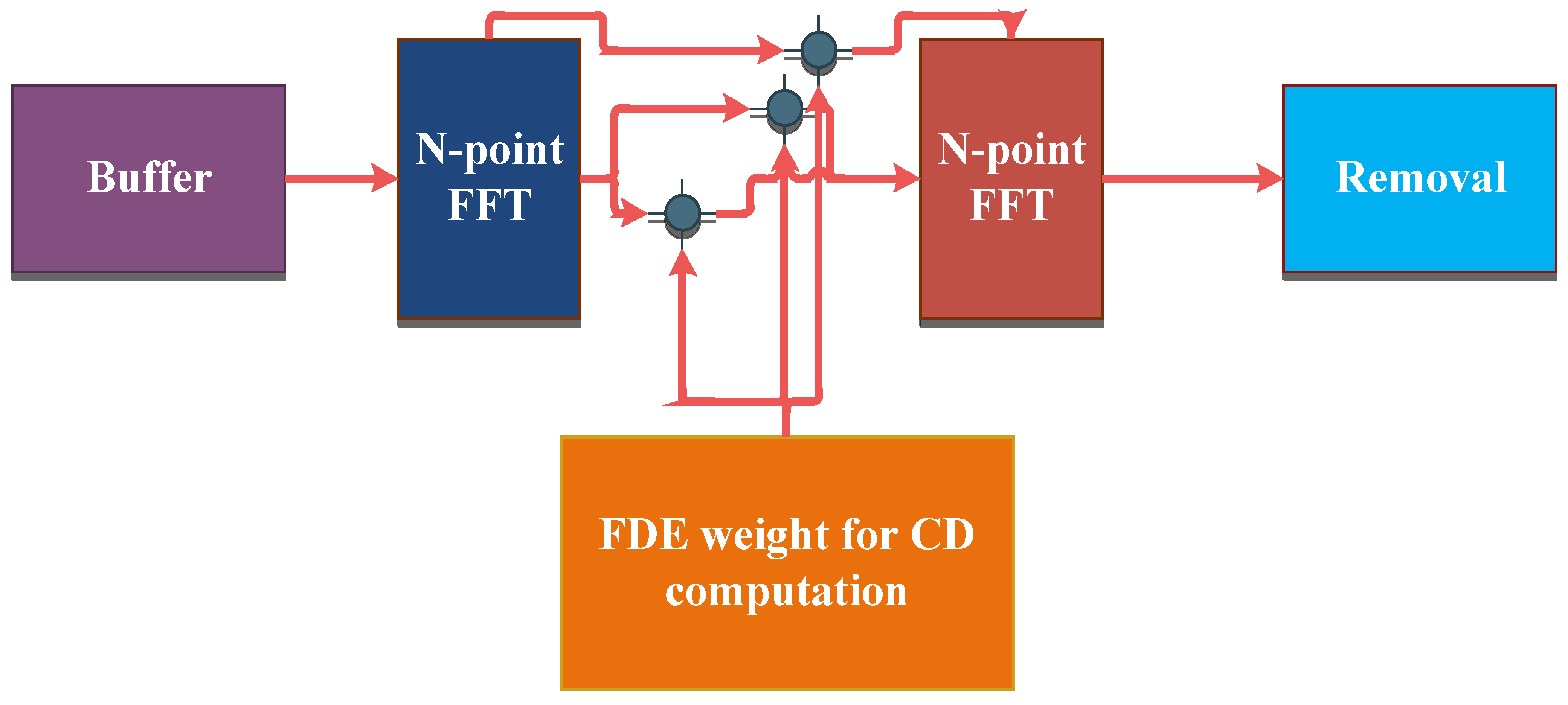
To improve transmission quality and reduce NLs and phase noise, FDE-based optical transmission was introduced in [
19]. This system is robust against phase noise with a basic FDE, but it fails to address the NLs in a long-haul optical RoF system. Therefore, an overlap FDE (OFDE) methodology is proposed in this work. The internal block of OFDE and TDE are explained in
Figure 2. The attained signals at the receiver side are demodulated by OFDE and TDE. OFDE compensates for the NLs, LDs, and phase noise, and TDE then operates following the timing and frequency synchronization. Furthermore, TDE measures the received weight, applying a constant modulus and blind algorithms and data signals. The tape size of OFDE is larger than TDE, so the impairments are reduced significantly. The TDE is followed by a carrier phase estimation technique conducting carrier recovery. The schematic procedure of OFDE is shown in the inset of
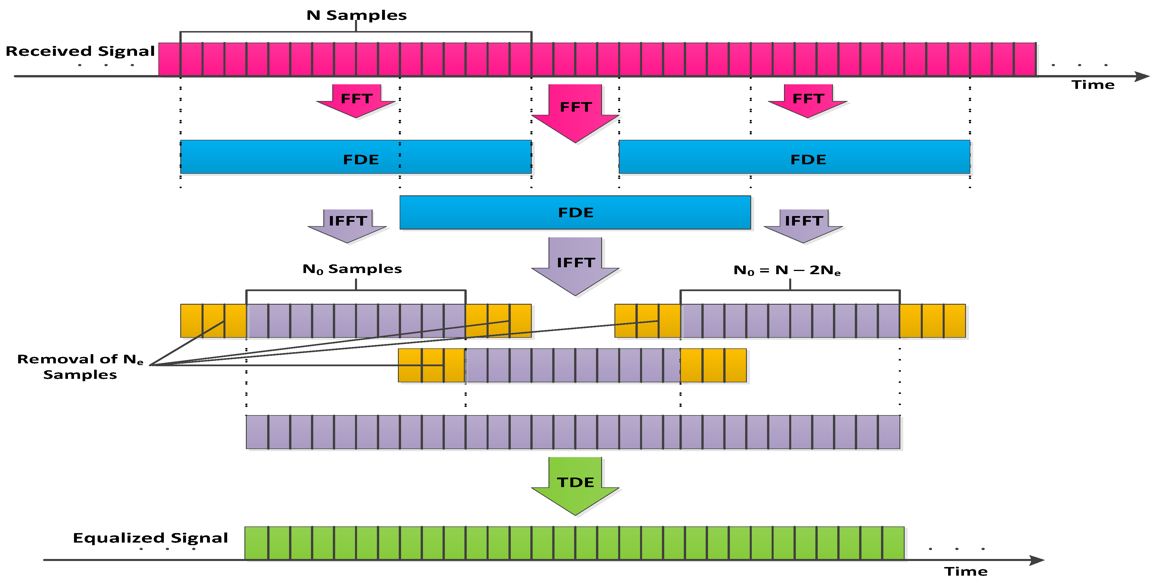
Figure 3, clarifying that a number of FDEs have a direct relation with the quantity of overlapping samples (Ns).
The transmission quality is increased in OFDE than in FDE, and the structure is simplified. These received signals are then multiplied by FDE blocks in the frequency domain with a fixed calculated weight. The first and last Nc samples from the N samples are omitted after inverse FFT (IFFT) N points. The remaining Nr samples are extracted, and compensated NL, LD, and phase noise signals are achieved regularly by performing FDE in an overlapped FFT block.
A BER analyzer is employed for measuring and analyzing the quality of attained signals in spite of NLs, LDs, and phase noise. The BER takes outputs from a 3R-re generator, which creates re-amplified, re-shaped, and re-timed signals to further increase accuracy. A list of elements for investigating the simulation analysis of the proposed research work is shown in
Table 1.
3. Analytical Modeling
The proposed model is described in
Section 2, while this section elaborates the theoretical proofs of the presented work. The transmitter ‘Tx’ of the OFTN receives the RF signals from base stations (BSs), [
22] which are estimated as
The parameter
denotes the RF received signals, and
describes the achieved signal length. A QAM block is used to attain the RF signals and divides it into two cascaded sequences, where each sequence is then transmitted with varying amplitudes ‘
’ [
23,
24] and computed as
where
shows the number of possible sequences. The parameter
i is the number of bits per symbol. The square of
N explains the range of the QAM. In other words,
and
define 4 QAM,
and
define 16 QAM,
and
define 64 QAM, and
and
define 256 QAM. In this research model,
and
along with
and
are analyzed [
25]. The string of bits coming from the QAM are split into two cascaded arrays. The output of QAM [
26,
27,
28,
29] is described as
Here, the real portion of the input signal is denoted by
J,
Q is used for the imaginary part,
C is the gain,
is the carrier frequency, and
is the phase of the signal. The PAPR is another key element for measuring the performance of the transmitted signal, which is evaluated from the QAM sub-carriers with
frequencies. The high range of PAPR is minimized by the electrical amplifier gain [
30,
31,
32] and is defined as
In the presence of PAPR, the NL, LD, and noise power spectral density (PSD) function [
33,
34] is induced and calculated as
Here,
is noise power, and
is the frequency grid spacing, which is defined as
where
is the channel spacing, and
is the noise ratio due to channel spacing. The pump laser is installed for transmitting RF signals over OFTL, which induces parameterized optical signals. The optical signals are mathematically estimated as
where
P is the average output power,
Z is used for power splitting, and
is the phase difference among the azimuth and explicit rays of light. From Equations (
1)–(
7), the cosine of the RF signal
is calculated as
where
is the driving voltage. The intensity modulation (IM) in terms of the optical field is written as
where
is the DC bias voltage, and
explains the IM half wave voltage. It is assumed that
and
, which explain the modulation index and the initial phase caused by
of the IM, respectively. From Equation (
9),
can be extended as
Here,
is the
order of the Bessel function. The transfer function of the transmitted signal is measured as
where
is written as
Here,
denotes insertion loss,
is the roll of factor, and
and
are calculated as
The system response is determined by the LDs. The attained signals are calculated as
where
N is the fast Fourier transform (FFT) size, the oversampling factor is denoted by
Z,
represents the duration of a single symbol, and
is the receive timing.
The NLs and LDs in the propagation of the light wave in the fiber are measured as follows:
Here
A represents the complex terms of the electromagnetic field,
t represents time, and
z denotes the distance of the fiber. For group velocity dispersion (GVD),
is used and is also known as linear dispersion;
is the non-linear dispersion parameter, attenuation is represented by
, and
is used as a non-linear coefficient. The relation among the non-linear refractive index
, the carrier wavelength
, and
is given by
The parameters that affect the amount of NLs and LDs are the cross-section area of SMF, the amount of light intensity propagating through the fiber, the number of channels in the WDM system, and the data rate. These factors generate an-harmonic motions of photons inside the SMF [
27], where the behavior of induced polarization
is no longer linear, and is given as
Here,
describes the free space permittivity,
E is the electrical field intensity, and
,
, and
determine the first-, second-, and third-order susceptibility, respectively. In order to calculate the frequency domain, the transfer function weight is measured as
Here,
is the speed of light,
l is the transmission distance,
D is the dispersion coefficient of the optical fiber,
f is the frequency of the base-band signals, and
is the center frequency of the optical signal. In Equation (
19), the dispersion slope is ignored due to its lower impact. The LDs are mainly caused by the group velocity dispersion in the fiber. The shift of the transfer function
is defined as
Because a high amount of LDs are generated in a long haul transmission, from the
N point of the IFFT, the first and last
samples are eliminated as depicted in
Figure 3. The overlapped samples that are needed can be obtained as
Here,
represents the spectrum edge of the received signal. Regarding the compensate phase noise, the equalizer coefficient using the received signal can be calculated as
where
M is the tap size of TDE,
A is the overlapping factor,
is the symbol duration,
n is the discrete time of the baud rate, and
is the receiving time. The equalizer coefficient inside the TDE is explained as
where
is the step size, and
is the measured transmitted signal, which is clarified as
In order to test the efficiency of the outcomes of the proposed work related to NLs, LDs, and phase noise, the BER anaylzer is employed at the receiver side. The bit rate is mathematically defined as
The
denotes error function. The optical signal-to-noise ratio (OSNR) is described as
where
defines the reference bandwidth,
is the electrical SNR,
is the total transmission symbol rate measured in Gbps, and the last term of Equation (
26)
is the system margin.
4. Results and Discussion
Section 3 shows that NLs, LDs, and phase noise interrupt the continuity of the WDM-RoF system. The impact of these impairments are studied based on simulation analysis in this section. Furthermore, the theoretical mechanism is linked with the simulation model. Equations (
1)–(
15) indicate the transmitted signal behavior, Equations (
16)–(
18) summarize the generation and impact of the LDs, NLs, and phase noise, Equations (
19)–(
24) demonstrate the proposed solution of NLs, LDs, and phase noise, and Equations (
25) and (
26) are used for evaluating the execution of the projected model.
Hence, the discussed theoretical model simulation analysis is performed as mentioned in
Figure 4,
Figure 5,
Figure 6,
Figure 7,
Figure 8,
Figure 9 and
Figure 10, estimating the data transmission ability in spite of the NLs, LDs, and phase noise. For this purpose, the dominant parameters include channel spacing, SMF transmission range, data rate capacity, input power, received power, and mmW RF bands.
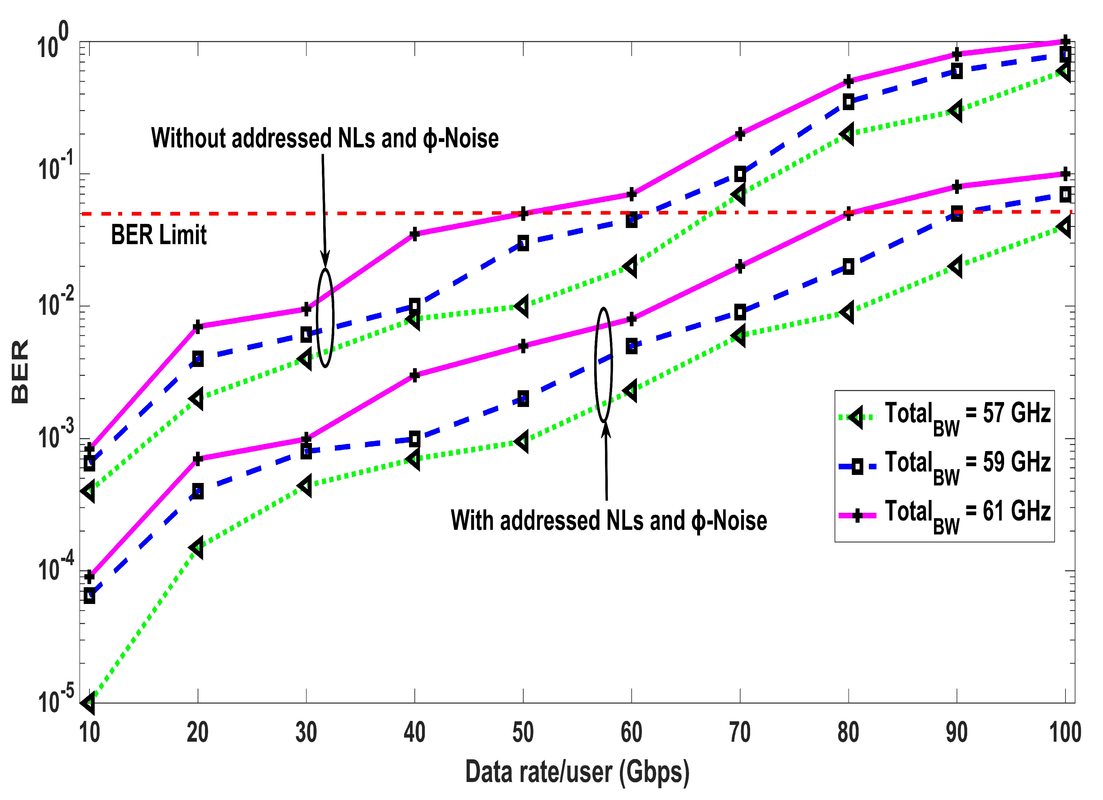
Figure 4 shows the relation between the data rate per user and the BER, and cases of 57 GHz, 59 GHz, and 61 GHz total bandwidth with and without NLs and phase noise are compared. The results in
Figure 4 show that NLs and phase noise badly distort the operation of a conventional WDM-RoF transmission. Moreover, from the results, it is shown that the order of NLs and phase noise also depends on the data rate. For data rates below 50 Gbps, the proposed RoF model gives a BER of less than
using NL- and phase noise-addressing mechanisms. On the other hand, BER values higher than the acceptable range are computed without using the proposed DSP receiver, as mentioned in
Figure 4. The simulation analysis of the WDM-RoF for 8, 16, and 32 channels (for a 10 km transmission range) based on the received power in dBm and the BER are presented in
Figure 5, comparing the performance of the cases with and without compensated NLs and phase noise. A range from −40 dBm to −20 dBm of received power is achieved, estimating that, up to −34 dBm, the attained BER is above the limit. With a greater number of channels, the range of BER is also increased, as shown in
Figure 5. About a two-digit difference is measured between the 32 and 16 channels transmission system. Furthermore, it is clarified from the results in
Figure 5 that the proposed WDM-RoF link with managed NLs and phase noise produces an efficient BER than without managed NLs and phase noise. Channel spacing between the propagating data plays a key role in the performance of the RoF system. Varying the space among channels makes a huge difference in the gain BER, as depicted in
Figure 6, containing information related to the channels and the BER. The model is tested based on 12.5 GHz, 25 GHz, and 50 GHz channel spacings and conclude that the the BER increases with decreasing channel spacing. Secondly, it is specified from
Figure 6 that not addressing NLs and phase noise gives a BER above the limited range.
Figure 7 explains the outcomes of 4, 16, 32, and 64 QAM-OFDM formats in terms of input power and BER. Between −20 dBm and 0 dBm of input power is launched in the proposed model, showing that the BER decreases with more power. Similarly, the performance of the proposed WDM-RoFL was investigated based on several phase noises, i.e., 0, 2.5, 5, and 8 deg, as defined in
Figure 8. The presented analysis considers a large bandwidth and a large number of WDM channels to ensure that the proposed system model covers the maximum limit for key performance indicators (KPIs) for future communication systems. A normalized optical signal-to-noise ratio (OSNR) was used here to ensure that the system performance is limited due to the Gaussian noise, and not the non-nonlinearities. The trend of the BER versus the OSNR shows that the proposed receiver effectively compensates the NLs and LDs, and hence can be used to implement RoF transport with high reliability.
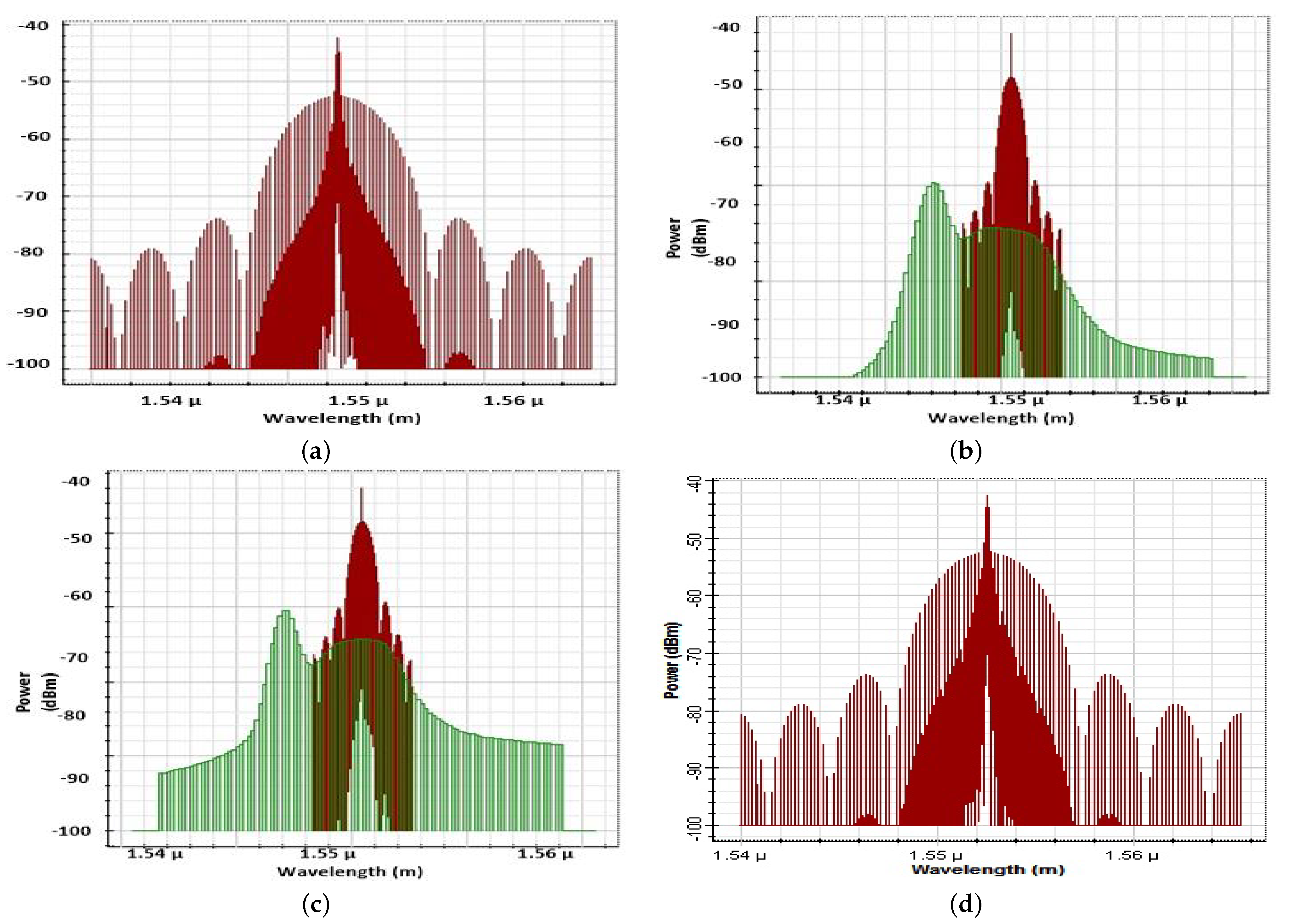
The model employing a BER analyzer and an optical spectrum analyzer was investigated and is shown in
Figure 9a,c and
Figure 10a,d, respectively.
Figure 9a shows the performance of the WDM-RoF model at a 20 km transmission range and at 61 GHz RF waves, when there is no technique addressed for controlling NLs, LDs, and phase noise.
Figure 9b presents the model without NLs, LDs, and phase noise compensated at 20 km and 59 GHz RF waves. The BER results of the WDM-RoF model where NLs, LDs, and phase noise are reduced are depicted in figure for 20 km and 61 GHz.
Figure 10a shows the input transmitted signals, and
Figure 10b,c show those without NL-, LD-, and phase-noise-managed signals at 10 km and 20 km of path cover with RF 59 GHz, respectively. The NL-, LD-, and phase noise-compensated output signals at a path cover of 20 km are presented in
Figure 10d. In addition, the performance of the proposed setup is analyzed for different lengths, channel spacings, and data rates, and compensation procedures of NLs, LDs, and phase noise are depicted in
Table 2. Similarly,
Table 3 clarifies the outcomes of the presented model and models from other publications in terms of channel spacing, BER, the length of SMF, and the methodology.
5. Conclusions
The WDM-RoF model is considered a promising solution in the current era for supporting a large number of users for high-data-rate-demanding multimedia-based services. Therefore, in this paper, a novel WDM-RoF model is projected based on OFDM modulated data transmission. NLs, LDs, and phase noise are studied and minimized in the presented model. The model is analyzed with an RF and optical domain infrastructure, and simulations are carried out using a realistic set of values. A mathematical model is investigated using the proposed analytical model to explore the originality of the transmitted signals, the discontinuity of pulses due to the optical domain, and electrical-domain-related issues, i.e. NLs, LDs, and phase noise. The presented model is investigated in a 1–20 km of transmission range, at 57–61 GHz RF bandwidths, at an input power between −20 and 0 dBm, at a received power from −40 dBm to −18 dBm, and with a 0–20 normalized signal-to-noise ratioThe complexity of the RoF link is reduced with enhanced quality by configuring the OFDE and TDE blocks at the 16/32/64 QAM-OFDM receiver. The OFDE and TDE configuration aims to handle NLs, LDs, and phase noise in SMF fibers installed as a backbone for RoF transmission. The simulation analysis shows that an RoF-transmission-based OFDE configuration is robust against NLs, LDs, and phase noise. It is found from the results that OFDE- and TDE-based RoF models are applicable for short- and long-range transmission. It is also concluded that the proposed solution provides a superior performance, with suppressed NLs, LDs, and phase noise as compared to conventional RoF systems.


 ,
, 


