A Maneuver Evaluation Algorithm for Lane-Change Assistance System


College of Intelligence Science and Technology, National University of Defense Technology, Changsha 410073, China
*
Author to whom correspondence should be addressed.
Electronics 2021, 10(7), 774; https://0-doi-org.brum.beds.ac.uk/10.3390/electronics10070774
Submission received: 28 February 2021
/
Revised: 21 March 2021
/
Accepted: 23 March 2021
/
Published: 25 March 2021
(This article belongs to the Section Electrical and Autonomous Vehicles)
Abstract
:This paper proposes a maneuver evaluation approach to enhance driving safety by providing decision aids. Based on the deliberative understanding of environmental semantic information, the proposed algorithm evaluates the risk of candidate driving maneuvers, including aggressive lane-change maneuver, passive lane-change maneuver, lane-change abort maneuver, and lane-keeping maneuver. The effectiveness of the proposed method is validated through various simulation experiments. The experimental results demonstrate that the proposed approach is capable of efficiently evaluating the feasibility and the cost of each candidate driving maneuver. The approach also provides suggestions on how to adjust the speed, and when to initiate a lane-change maneuver.
1. Introduction
In order to ensure the safety of driving and improve the efficiency of transportation, intelligent driving technology is developing rapidly. Nowadays, intelligent driving assistance systems and partially automated driving technologies are gradually entering the market. The SAE On-Road Automated Vehicle Standards Committee introduced various levels of driving automation [1], including Level 1 (Driver Assistance), L2 (Partial Automation), Level 3 (Conditional Automation), Level 4 (High Automation), and Level 5 (Full Automation). Automated lane change systems have already been integrated in some commercial applications of Level 2 systems, such as Tesla Autopilot and GM Super Cruise [2]. Some institutions are testing the deployment of Level 4 systems, such as Waymo, GM, Daimler, BMW, Ford, Volvo, and Baidu [3]. There still remains many unresolved problems for automated driving in complex traffic scenarios, including perception, decision-making, and trajectory planning. UNECE recently published an official regulation on automated lane keeping systems (ALKS) [4]. In its current form, the regulation limits the speed of ALKS to a maximum of 60 km/h. Due to technical limitations and people’s acceptance of automated driving technology, it is crucial that intelligent driving assistance systems should be sufficiently developed before the realization of automated driving.
There are different strategies for the machine to assist the driver. The assistance system can help the driver make safe decisions or realize assistant control. In [5], a radical strategy is utilized. When the situation is judged to be dangerous, the system intervenes, and the machine determines the final decision and steering angle. In [6], a conservative strategy is adopted. If the driver represents the intention of the lane-change maneuver, or the system predicts that the driver wants to change lane, the decision algorithm can evaluate whether it is safe to change lane. The assistance system provides decision-making assistance and allows the driver to make the final decision.
There are some works that have been conducted to improve the capabilities of the system, including trajectory prediction, threat assessment, and recommendations regarding lane-change decisions. The turning signal is the most exact message that can express the intention of lane change. Other indicators, including the steering angle, heading angle, latitudinal distance to lane markers, and the time to cross lane (TLC), can also be employed to determine whether the driver wants to initiate a lane-change maneuver. Some scholars have studied the vehicle trajectory prediction problem based on machine learning and model-based methods [7,8,9,10]. In [6], a Bayesian classifier for the identification of lane-change intention is established by learning from the data of the distance gap and closing speeds. In [11], the parameters of the lane change model extracted from the Next Generation Simulation (NGSIM) dataset are used to predict vehicle trajectory. In our previous work [12,13], the lane-change intention of the drivers is predicted by using a dynamic Bayesian network framework.
Single behavior threat metrics have been widely used for threat assessment. Time-related metrics, including the time-to-collision (TTC) [14], time-to-react (TTR), or time-to-brake (TTB) [15,16,17], and acceleration related metrics [18,19] are used to evaluate the threat. The heading angle of the vehicle changes while avoiding obstacles. In collision avoidance scenarios, these indicators cannot reflect the influence of changes in the heading angle. Due to such limits, it is difficult to obtain the accurate safety critical value of the metrics for safety assessment. When using this type of indicator, a conservative strategy is usually adopted in order to prevent collisions. The risk can be defined as the probability of collision [20]. The authors of [19] conducted threat assessment by calculating the collision probability with consideration of the multiple traffic reachable set. In [21], the authors used extended Kalman filters (EKF) to predict the future state and then calculated the collision probability. The algorithm determines whether the vehicle-body-shaped polygons of the host vehicle and traffic participants can be intersected. By applying formalized verification methods, the safety of lane change maneuvers are verified in [22]. In [23], the authors evaluate whether the reserved spaces is suitable for lane change to determine the feasibility of lane change maneuver.
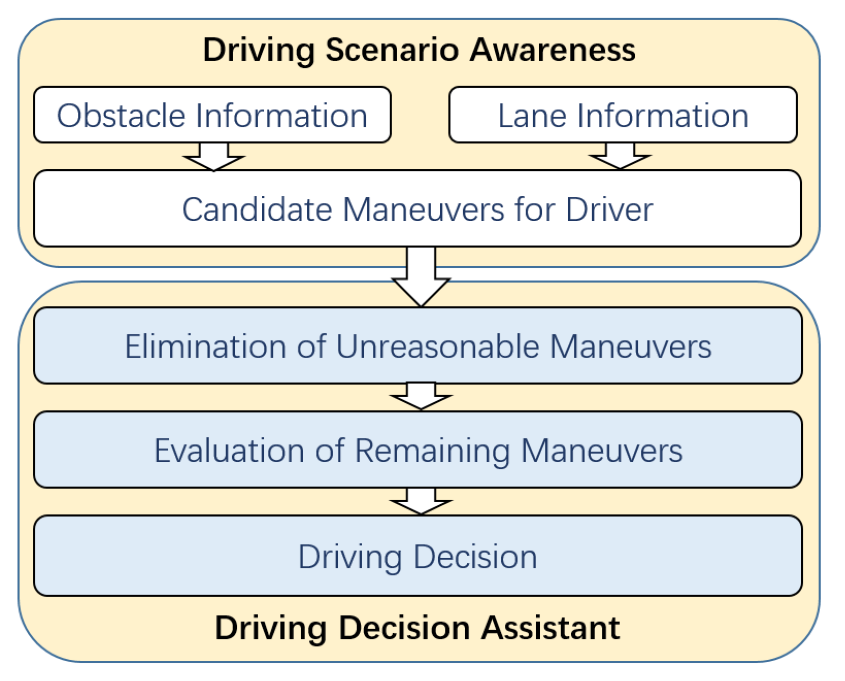
The proposed maneuver evaluation method in this paper is different from the above papers. In this paper, the proposed maneuver evaluation algorithm not only verifies the risk of the traffic scenario, but also quantifies the candidate driving maneuvers. At the same time, the optimal maneuver is obtained. Suggestions regarding the speed adjustment strategy and lane-change timing for the lane-change maneuver are provided. The framework of the proposed maneuver evaluation algorithm is shown in Figure 1.
In this paper, the proposed method belongs to Level 1 according to the SAE driving automation standard [1]. The driving scenario awareness module receives perception information from on-board sensors. To guarantee a better understanding of the traffic situation, the environment semantics are analyzed to identify candidate driving maneuvers. In the driving decision module, the unreasonable candidate driving maneuvers are eliminated, and the remaining candidate maneuvers are quantified and evaluated. Finally, the driving decision is provided.
The contributions of this work are twofold. First, the safe distances considering lateral motion and longitudinal motion for continuing lane-change maneuver and canceling lane-change maneuver are discussed. To the author’s knowledge, only a few studies have discussed the safe distance for canceling lane-change maneuver. Second, a maneuver evaluation algorithm for lane-change decision-making is proposed, and the feasibility for each candidate maneuver is quantified and evaluated. The hard constraints on safety distance combined with the soft constraint that suggests that the vehicle should not interfere with the normal driving of other vehicles are taken into consideration.
The remainder of this paper is organized as follows: In Section 2, the driving scenario awareness module is introduced. In Section 3, the safe distance requirements for lane keeping, lane change, and canceling lane change are described. In Section 4, we propose the algorithm for evaluating candidate driving maneuvers. In Section 5, the experiment results are shown. Conclusions are drawn in Section 6.
2. Driving Scenario Awareness
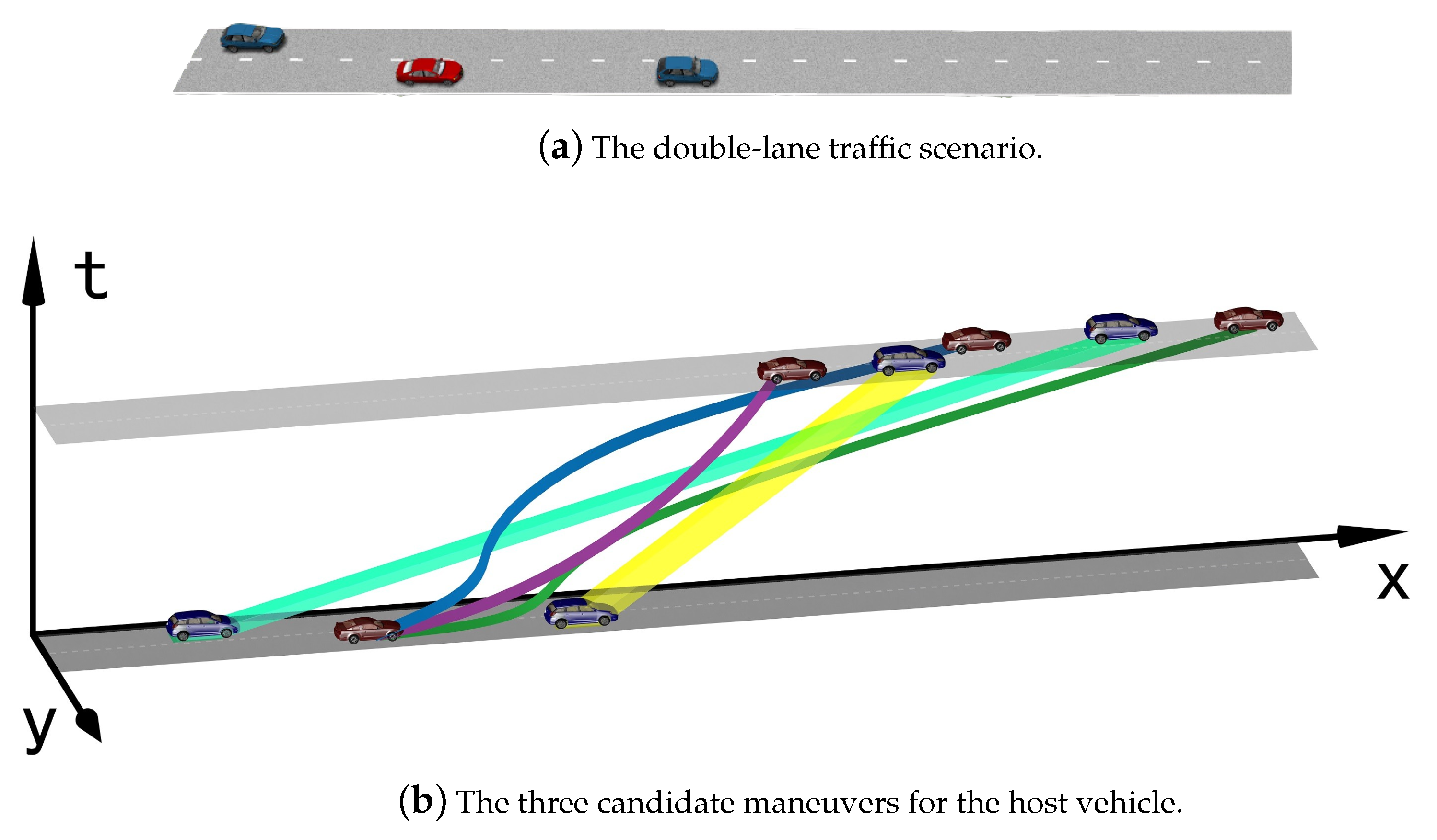
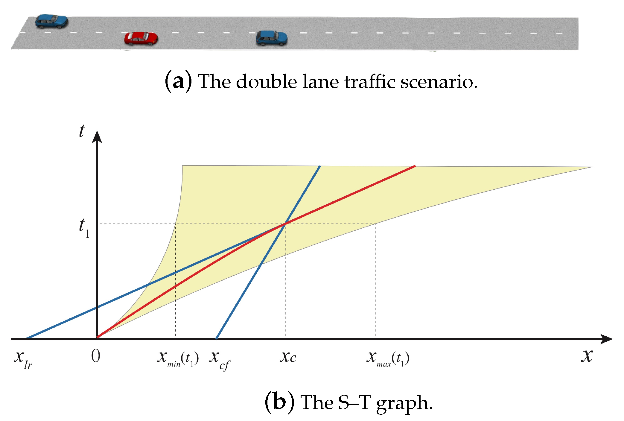
Driving maneuvers are largely dependent on the context. Each series of actions that a driver can take corresponds to a maneuver, such as lane keeping, lane change, left turn, and right turn. The lane-change decision-making algorithm should have the ability to reason the driver’s candidate maneuver patterns. According to the relative position of surrounding vehicles, the preliminary candidate corridors can be obtained. Each corridor corresponds to a specific driving maneuver. A double-lane traffic scenario is shown in Figure 2, in which the red vehicle is the host vehicle.
In the dynamic traffic scenario shown in Figure 2a, the red vehicle represents the host vehicle, and the speed of the left rear blue vehicle on the right lane is higher than that of the front vehicle. Considering the spatio-temporal information, the host vehicle has two candidate lane-change maneuvers and a lane-keeping maneuver, as shown in Figure 2b. The host vehicle may perform an aggressive maneuver and overtake the left rear vehicle. Moreover, it can perform passive maneuvers and change lane after the left rear vehicle passes it. The host vehicle may also perform the lane-keeping maneuver. The decision-making module should have the ability of reasoning and evaluate the safety of optional maneuvers.
3. Safe Distance for Candidate Driving Maneuvers
The motion of the host vehicle is subject to a variety of constraints, including the vehicle kinematic limits, and collision avoidance with the road and obstacles. In this paper, the safe distance required for lane keeping, lane change, and canceling lane change is discussed. Hallerbach et al. [24] introduced a toolchain for identifying critical scenarios. The authors used standard safety metrics, such as TTC and TTB; the required deceleration ; and combined traffic quality metrics to evaluate the traffic. The paper only considered the metrics in terms of longitudinal motion. The lateral motion cannot be reflected exactly by the used metrics. Since the outer boundary of the vehicle is affected by the heading angle of the vehicle, different lateral positions and heading angles of the host vehicle may lead to different results in identifying critical scenarios, which was not considered in [24]. In this paper, the lateral motion and longitudinal motion are taken into consideration for calculating the safe distance during lane change. The influence of the outer boundary of the host vehicle on safe distance can be more accurately reflected.
3.1. Driving Maneuver of Lane Keeping
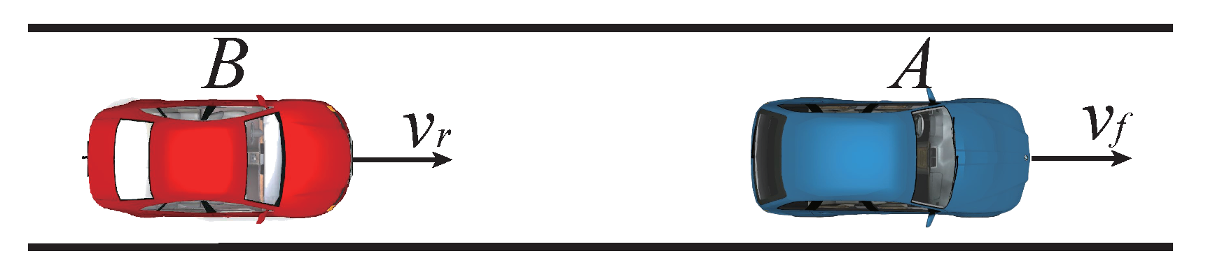
The scenario for the lane-keeping maneuver is shown in Figure 3. Inspired by the responsibility-sensitive safety (RSS) model proposed by Mobileye [25], the safe distance for the lane-keeping maneuver is defined below.
The velocity of the front vehicle A is , and the longitudinal velocity of the rear vehicle B is . The safe distance is obtained assuming that vehicle A decelerates at until it stops, while vehicle B drives at during the reaction time and decelerates at until it stops. If the two vehicles do not collide during the entire process, then the distance is safe.
3.2. Driving Maneuver of Lane Change
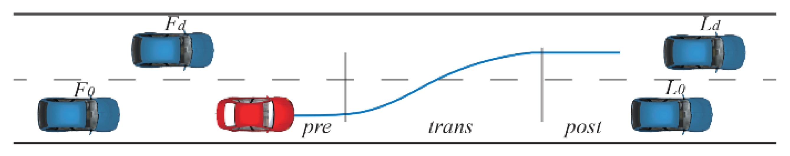
In this paper, to simplify the calculation of safe distances of lane-change maneuver in structured roads, the motion is divided into lateral motion and longitudinal motion in the lane frame. The lane-change process is divided into three stages, namely, the preparation period, the transition period, and the post period, as shown in Figure 4.
In each stage, the host vehicle follows different longitudinal position constraints. In the preparation period, the host vehicle adjusts the speed and position to obtain enough space for lane change. During the transition period, the host vehicle crosses the lane line, and the position is constrained by the four vehicles in the target lane and in the original lane. In the post period, the position of the host vehicle is only constrained by the front and rear vehicles in the target lane. The longitudinal position constraints during the lane change process are as follows.
and are the longitudinal positions of the front and rear vehicles in the original lane. and are the longitudinal positions of the front and rear vehicles in the target lane. , , , and are the required longitudinal safe distances. and are the maximum and minimum longitudinal positions in the preparation period. and are the maximum and minimum longitudinal positions in the transition period. and are the maximum and minimum longitudinal positions in the post period.
In this paper, motion is divided into lateral motion and longitudinal motion. A lateral motion model is utilized, in which the lateral acceleration is assumed to be a sinusoid function of time.
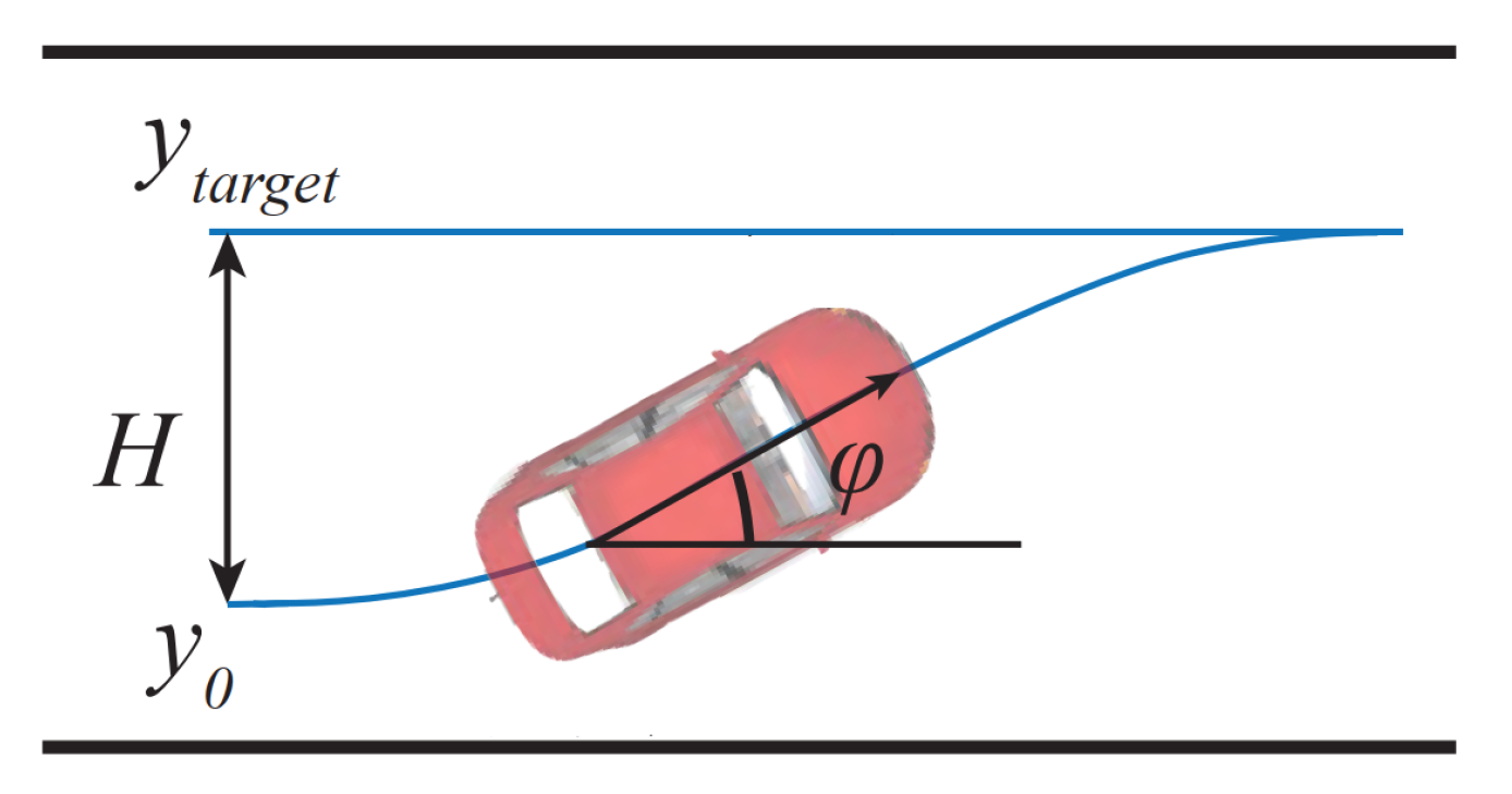
where is the lateral acceleration in the lane frame, H is the total lateral distance to complete the lane-change process the in lane frame, is the total lateral motion time, is the lateral position before the lane-change maneuver, and is the terminal lateral position, as shown in Figure 5. The longitudinal motion is assumed to be uniformly accelerated.
Thus, the heading angle during the process of lateral motion can be obtained.
Based on the lateral motion model, assuming that the heading angle equals , the time required from the vehicle initiating lateral motion can be derived.
If a lateral terminal position in the lane frame and the current lateral terminal position are determined, and can be obtained by sampling the and comparing with .
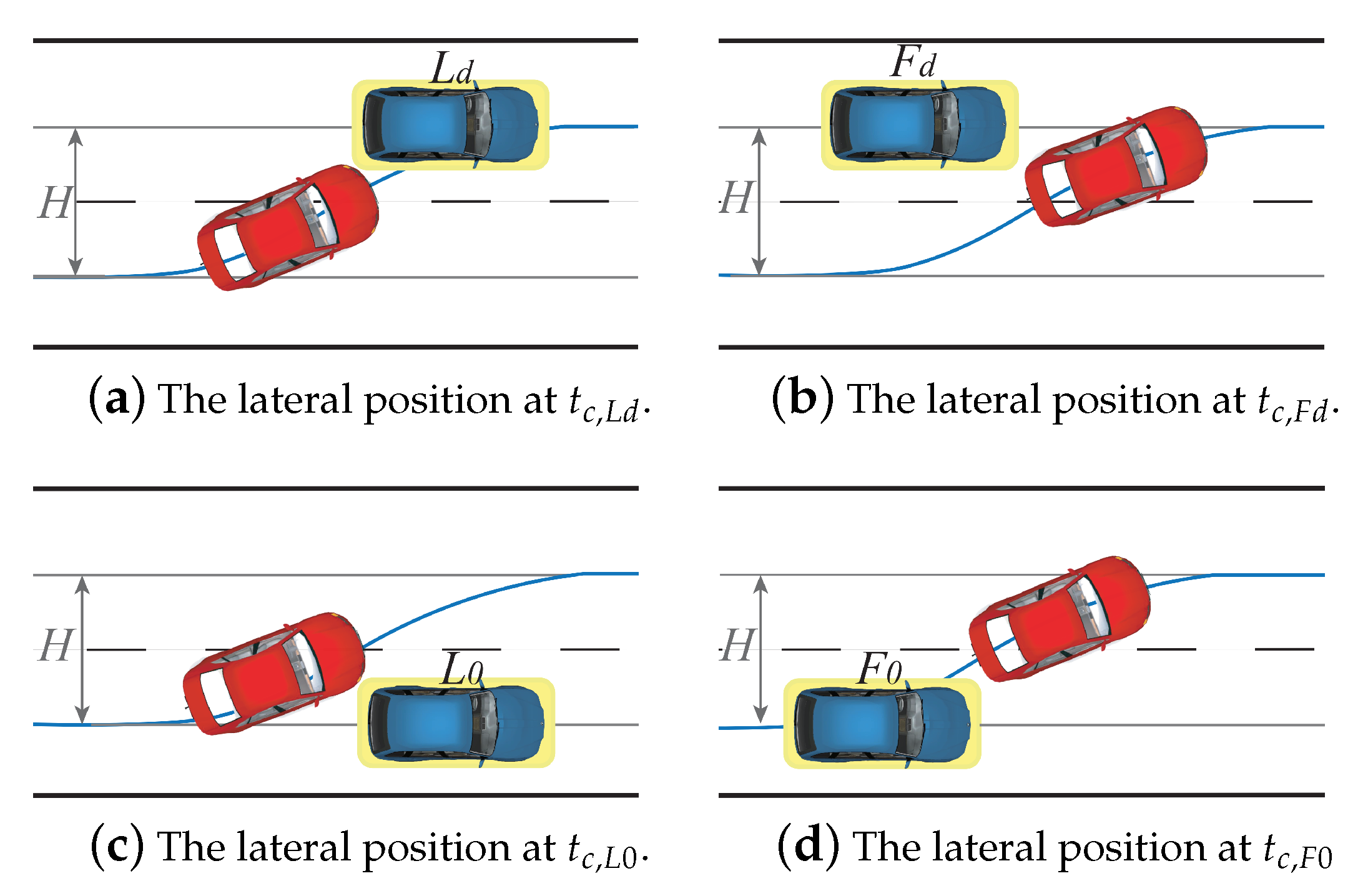
In [26], Jula et al. derived the safe longitudinal distance for lane change. However, the safe longitudinal distance during lateral motion was not derived. In this paper, we modify the safe distance to obtain the safe longitudinal distance during lateral motion. In order to calculate the longitudinal safe distance, the following critical lateral positions for the host vehicle are defined, as shown in Figure 6.
The time required to move from the current state to the critical position can be calculated. Since the longitudinal motion time equals the lateral motion time, given the prediction horizon T, the safe longitudinal distance for the current state can be obtained.
3.3. Driving Maneuver of Canceling Lane Change
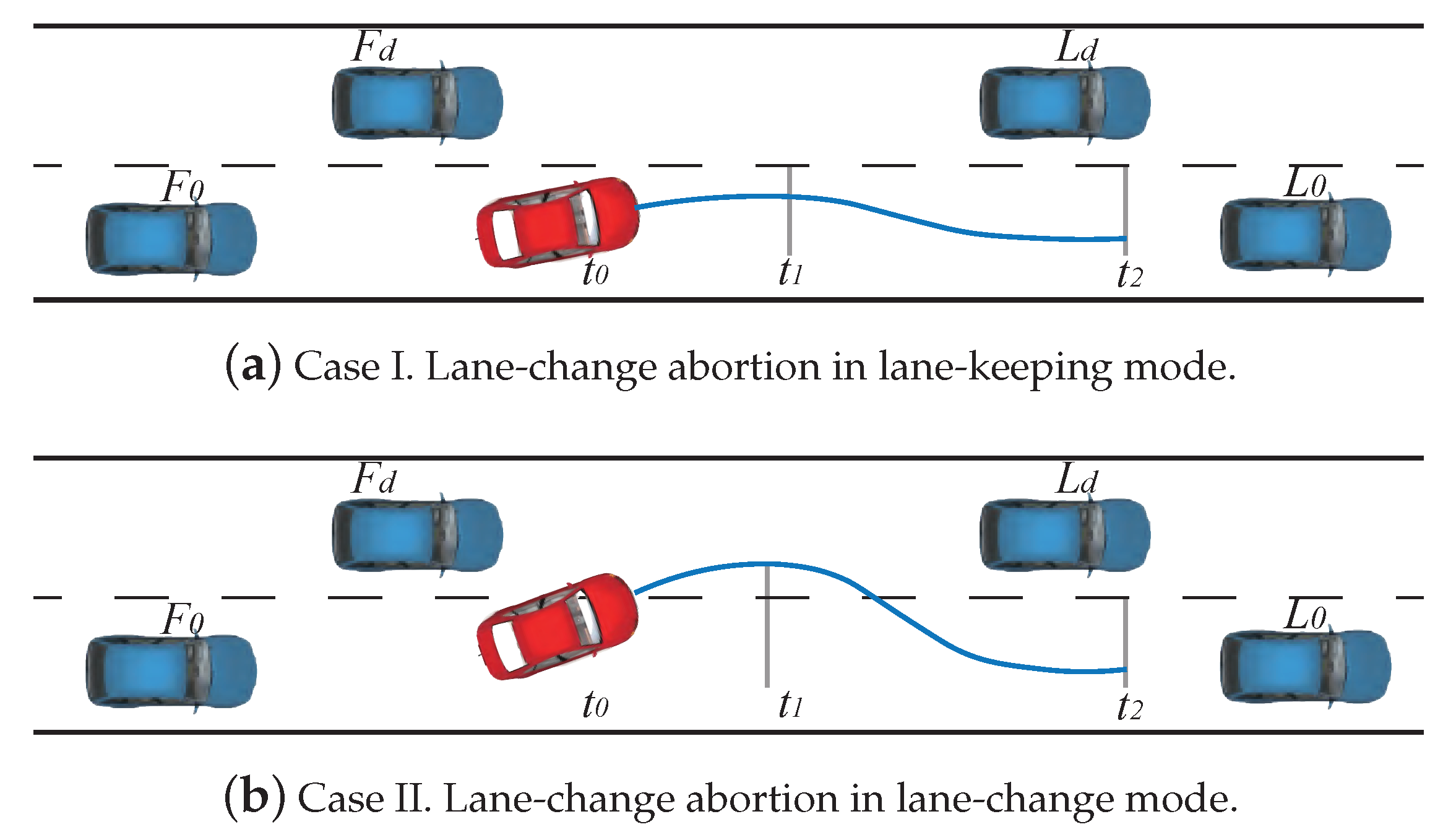
During the transition period of the lane-change process, the insufficient gap may make the lane change infeasible if the surrounding vehicles are driving uncooperatively. The driving assistance system should continuously evaluate the safety of continuing the lane-change maneuver and judge whether the lane change should be canceled. We divided the lane-change canceling process into two major stages, as shown in Figure 7. In the first stage, the vehicle adjusts the lateral velocity and the heading angle. In the second stage, the vehicle continues to travel to the original lane.
During the first stage, it is assumed that the host vehicle moves at constant lateral acceleration . At time , the vehicle’s heading is paralleled to the lane line, and the lateral velocity is zero.
According to the lateral position at , the lane-change abort scenario can be divided into two cases. As shown in Figure 7a, if the host vehicle has not entered the target lane at , the position is constrained by the front and rear vehicle in the original lane. The host vehicle can adjust its velocity in lane-keeping mode. Otherwise, if the host vehicle enters the target lane at (Figure 7b), the position is constrained by the vehicles in both lanes. The traffic scenario at time is the same as the right lane-change scenario.
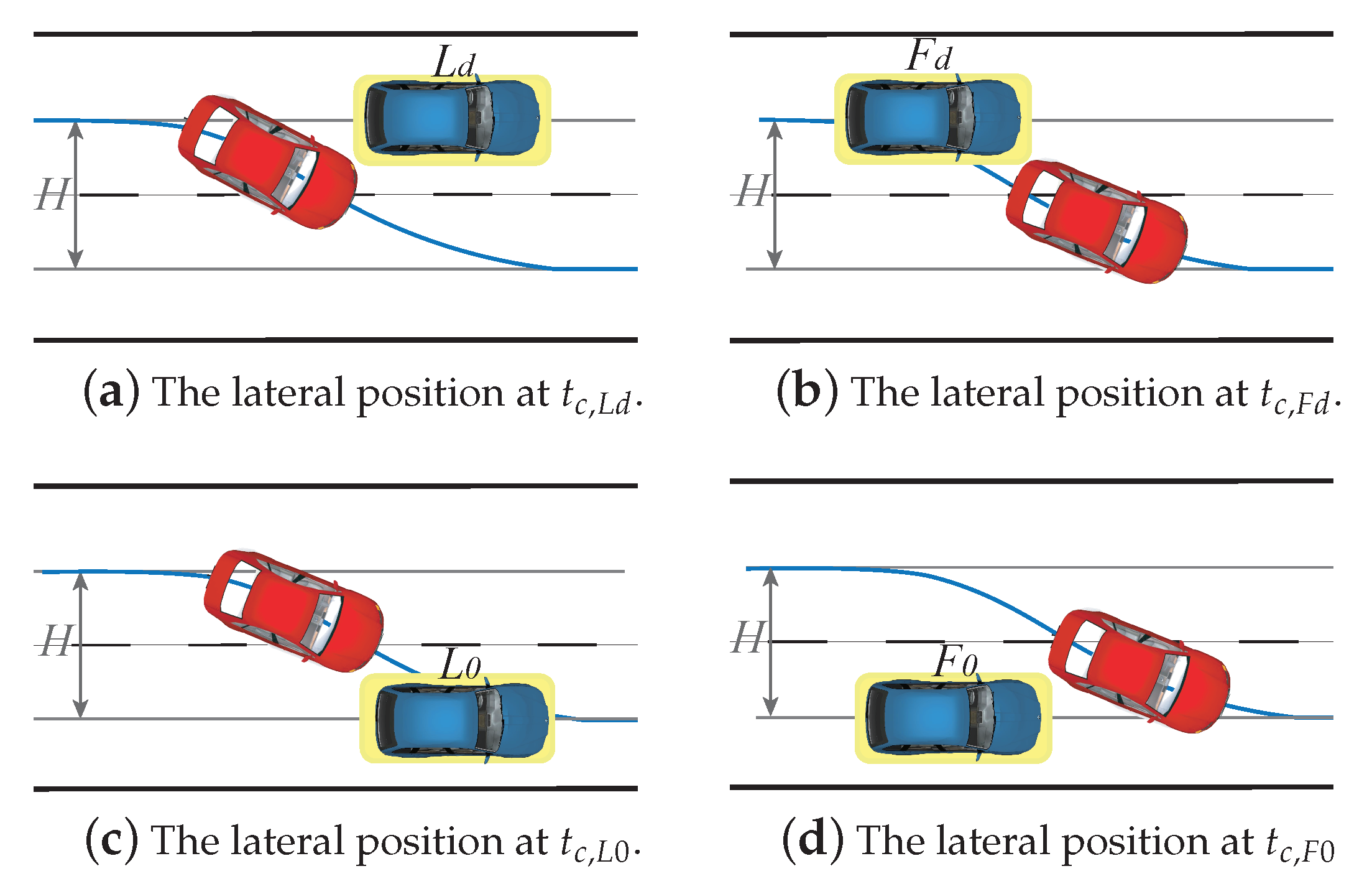
For the second case, the lane-change abortion process is divided into three stages, namely, the adjustment period, the transition period, and the post period. In the adjustment period, the host vehicle adjusts the lateral velocity and heading angle. In the transition period, the host vehicle returns to the original lane. In the post period, the host vehicle adjusts the speed and position in the original lane. In each phase, the host vehicle follows different constraints in the longitudinal position. Similarly to the left lane-change scenario, the critical lateral position for the right lane-change can be defined as shown in Figure 8.
where is the time used to adjust the lateral velocity to zero in the adjustment period, and is the lateral movement time it takes to move from the lateral position at time to the critical lateral position . T is the prediction horizon.
4. Evaluation of Candidate Driving Maneuvers
4.1. Elimination of Unreasonable Driving Maneuvers
The candidate driving maneuvers can be truncated according to the limitation of motion and the basic spatial-temporal constraints. The motion can be divided into lateral and longitudinal motion in the lane frame. The longitudinal motion of a vehicle is affected by its power and deceleration ability. The acceleration of the host vehicle is limited by the friction force, longitudinal weight transfer, bank and grade affect, etc.. The permissible speed is limited by curvature of the path and maximum allowed speed by traffic rules. The vehicle should follow the constraints in Table 1.
Considering the spatial-temporal constraint, the lateral motion is constrained by the vehicles in the original lane and the target lane. To explain the spatial-temporal constraint clearly, we take a simple scenario of one vehicle in the current lane and one in the adjacent lane as an example, as shown in Figure 2. The host vehicle has three candidate maneuvers, including overtaking the left vehicle, following the left vehicle, and lane keeping. The S-T graph is shown in Figure 9.
In Figure 9, the yellow area represents the set of longitudinal positions that the vehicle can reach in the prediction time domain. At time , the positions of the front and the left vehicle are and , respectively. If the surrounding two vehicles drive at a constant speed, they will arrive at the same longitudinal position at time . Due to the limitation of acceleration, the longitudinal position of the vehicle will be between and at time . If the driver chooses to overtake the vehicle in the left lane, the host vehicle should enter the left lane before time , and the longitudinal position of the host vehicle should be greater than at , and needs to be satisfied. The host vehicle moves at the required minimum longitudinal acceleration to overtake the left vehicle, as shown by the solid red line in Figure 9. If the driver chooses to follow the vehicle in the left lane, the longitudinal position of the host vehicle should be smaller than the left vehicle when the host vehicle enters the left lane. Therefore, the solid red line in Figure 9 represents the longitudinal motion when the host vehicle moves at maximum longitudinal acceleration to follow the left vehicle.
4.2. Evaluation of Remaining Driving Maneuvers
After the unreasonable candidate maneuvers are eliminated, the remaining candidate maneuvers are evaluated. An algorithm is proposed to evaluate the feasibility of the driving maneuver, as shown in Algorithm 1. If the current situation does not meet the requirements of the safe lane-change maneuver, the algorithm evaluates whether the constraints can be met by accelerating or decelerating. The sub-optimal speed adjustment solution with the longitudinal acceleration range , the feasible interval of time , and the cost for each driving maneuver is obtained. Therefore, the optimal driving maneuver with the lowest cost and the speed adjustment solution can be achieved.
| Algorithm 1 Maneuver evaluation |
| Input: Candidate maneuvers , state |
| Output: Speed adjustment solution set , longitudinal acceleration range , initiating time interval , cost for each corridor |
|
A cost function is designed to compare the solutions to each driving maneuver. The goal of optimization is to achieve a balance among the lane-change starting time, longitudinal acceleration, and gap with other vehicles. For the lane-change maneuver, we consider the following min–max problem with the parameters , , and , where is the longitudinal acceleration for speed adjustment; is the lane-change starting time; and is the penalty, which reflects the gap with other vehicles. We obtain the earliest safe initiating time and the last safe initiating time for each . To ensure that the driver has ample operation time to prepare for the lane-change maneuver, the time interval between and should be no less than if the driver has not initiated the lane-change maneuver.
For each pair of host vehicle and safe-related traffic vehicle (, , , and ), we calculated the safe acceleration-related indicator to reflect the degree of safety. Assuming the distance at critical times , , , and between the two vehicles before braking is d, the front vehicle brakes at acceleration , and the rear vehicle moves at acceleration during the reaction time and then starts to brake at to ensure no collision occurs. The minimum required deceleration for the rear vehicle can be obtained.
For the rear vehicle, the smaller required means that it is safer. Based on the distance from host vehicle to , , , and during the lane-change process, can be derived. The cost for each lane-change maneuver can be obtained. For the lane-keeping maneuver, the cost can be defined as presented below, where is computed based on the distance from the front vehicle .
5. Experiments and Discussion
5.1. Driving Maneuver Evaluation before Lane-Change Process
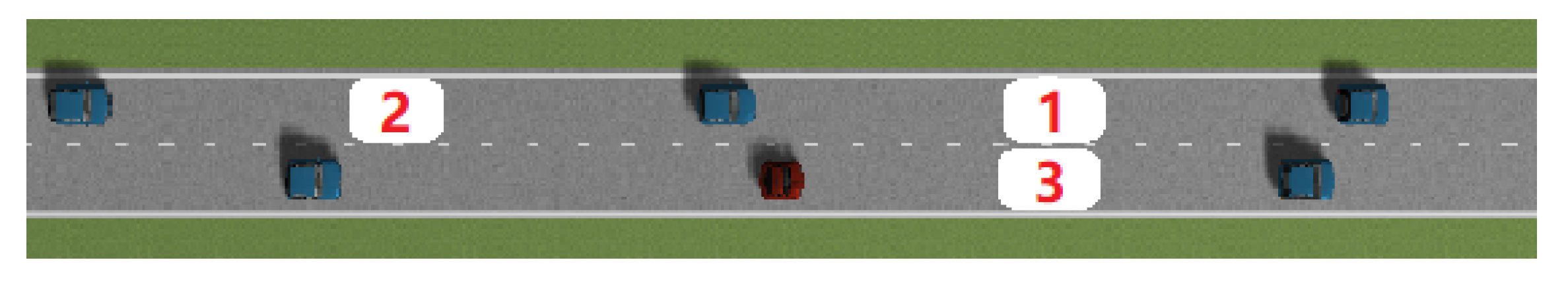
To validate the proposed algorithm in traffic scenarios, simulation experiments were conducted using the Prescan simulation environment [27]. The traffic participants move at a constant speed. The red vehicle is the host vehicle, which drives forward along the right lane. The three decision-level driving maneuvers are shown in Figure 10.
The host vehicle may implement an aggressive maneuver of speeding up and then initiate a lane-change maneuver for corridor 1. Alternatively, the vehicle may implement a passive maneuver of waiting until there is enough space for corridor 2. For corridor 3, the host vehicle follows the front vehicle in lane-keeping mode. The parameters for simulation are shown in Table 2.
The feasibility of each driving maneuver is evaluated. The cost, speed adjustment solution, and suggested time to initiate lane- change maneuver are obtained during the process of driving forward. When the safety constraints are satisfied, the algorithm provides a signal that suggests initiating a lane-change maneuver. The code is implemented in C++ using Intel I7-10750 cpu running at 3.9 GHz, the average total time used is about 5 ms.
(a) = 0
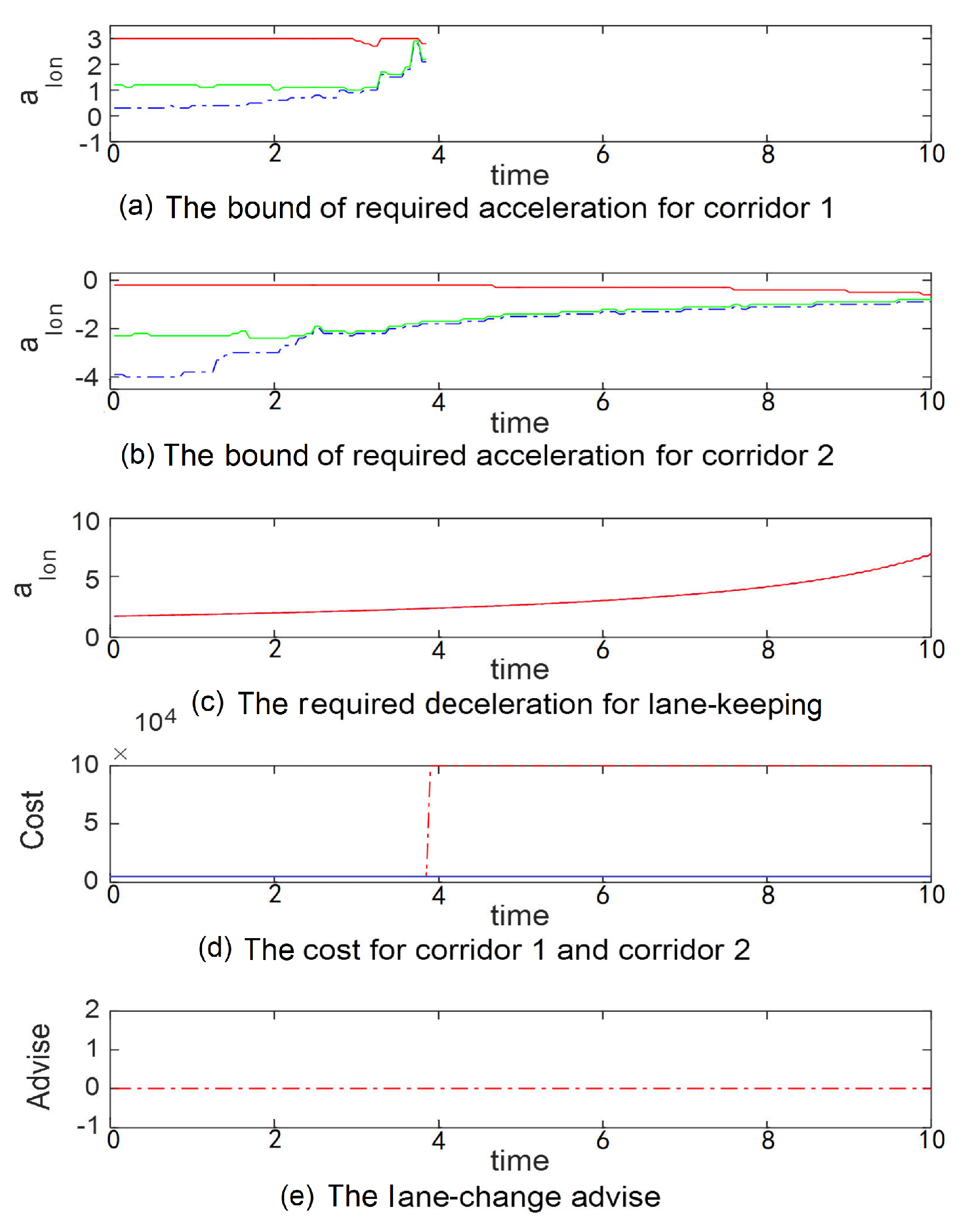
Figure 11 shows the simulation results of the host vehicle moving forward at constant velocity.
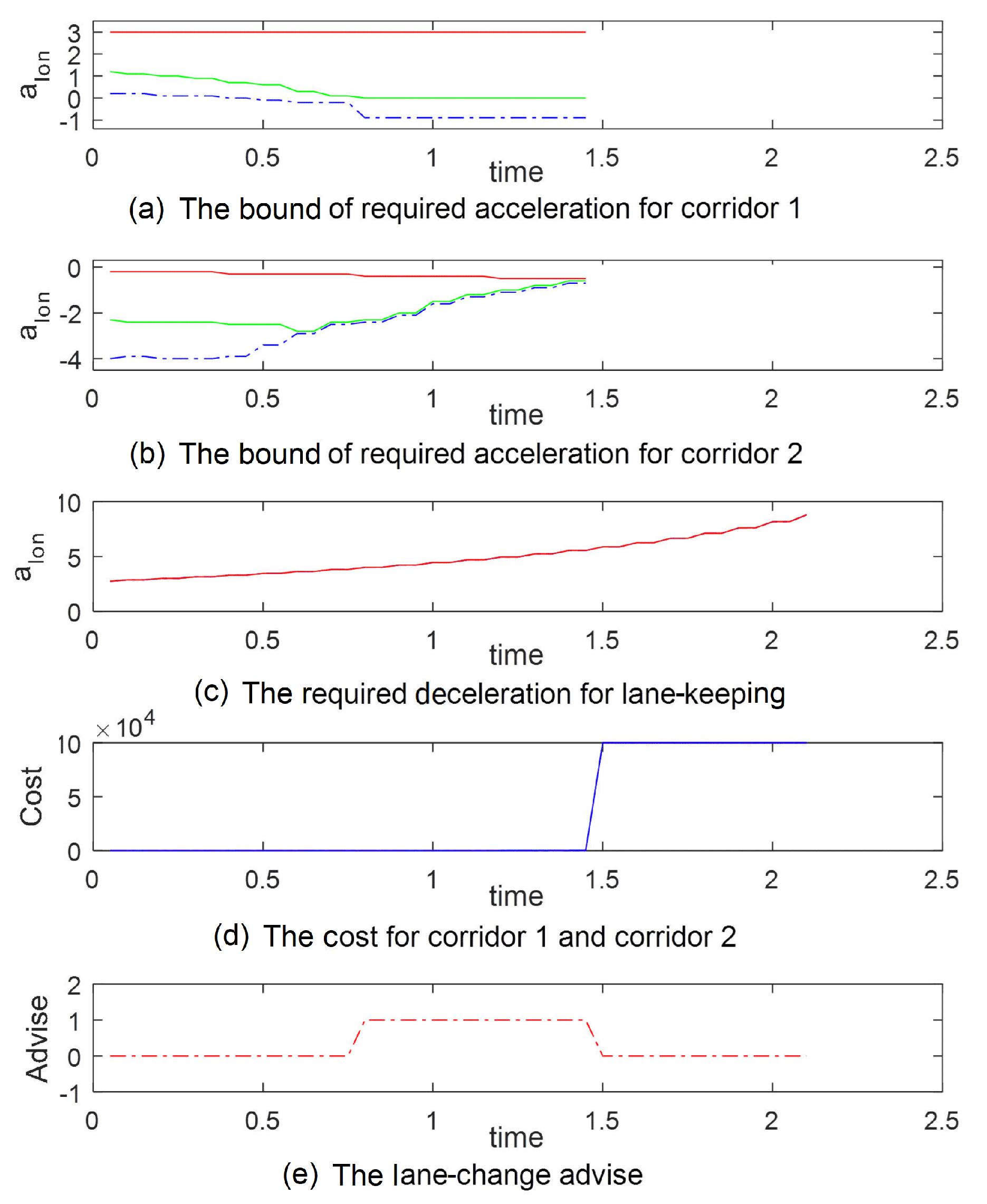
In Figure 11a,b the solid red line represents the maximum safe longitudinal acceleration, the dashed blue line represents the minimum safe longitudinal acceleration, and the solid green line represents the recommended longitudinal acceleration with the lowest cost. In Figure 11c, the solid blue line represents the required minimum longitudinal deceleration for lane keeping. In Figure 11d, the dashed red line represents the cost for corridor 1, and the blue line represents the cost for corridor 2. In Figure 11e, when the signal is 1, it means that the driver can perform a lane-change maneuver safely. As shown in Figure 11a, for corridor 1, the recommended acceleration is about 1 m/s from the beginning to 3.8 s. The velocity of the left lane is greater than that of the right lane, the gap for changing lane decreases, and the cost increases gradually. After 3.8 s, the cost for corridor 1 becomes a large value, and lane-change is infeasible. As shown in Figure 11b, for corridor 2, the recommended acceleration is initially about −2 m/s, and then it increases gradually. Corridor 2 is feasible if the host vehicle can slow down and obtain enough space to change lane. Figure 11e shows that during the whole process, the lane-change maneuver is not recommended under the current velocity. For corridor 3, the speed of the host vehicle is greater than that of the front vehicle. As the host vehicle approaches the vehicle in front of it, the required deceleration increases.
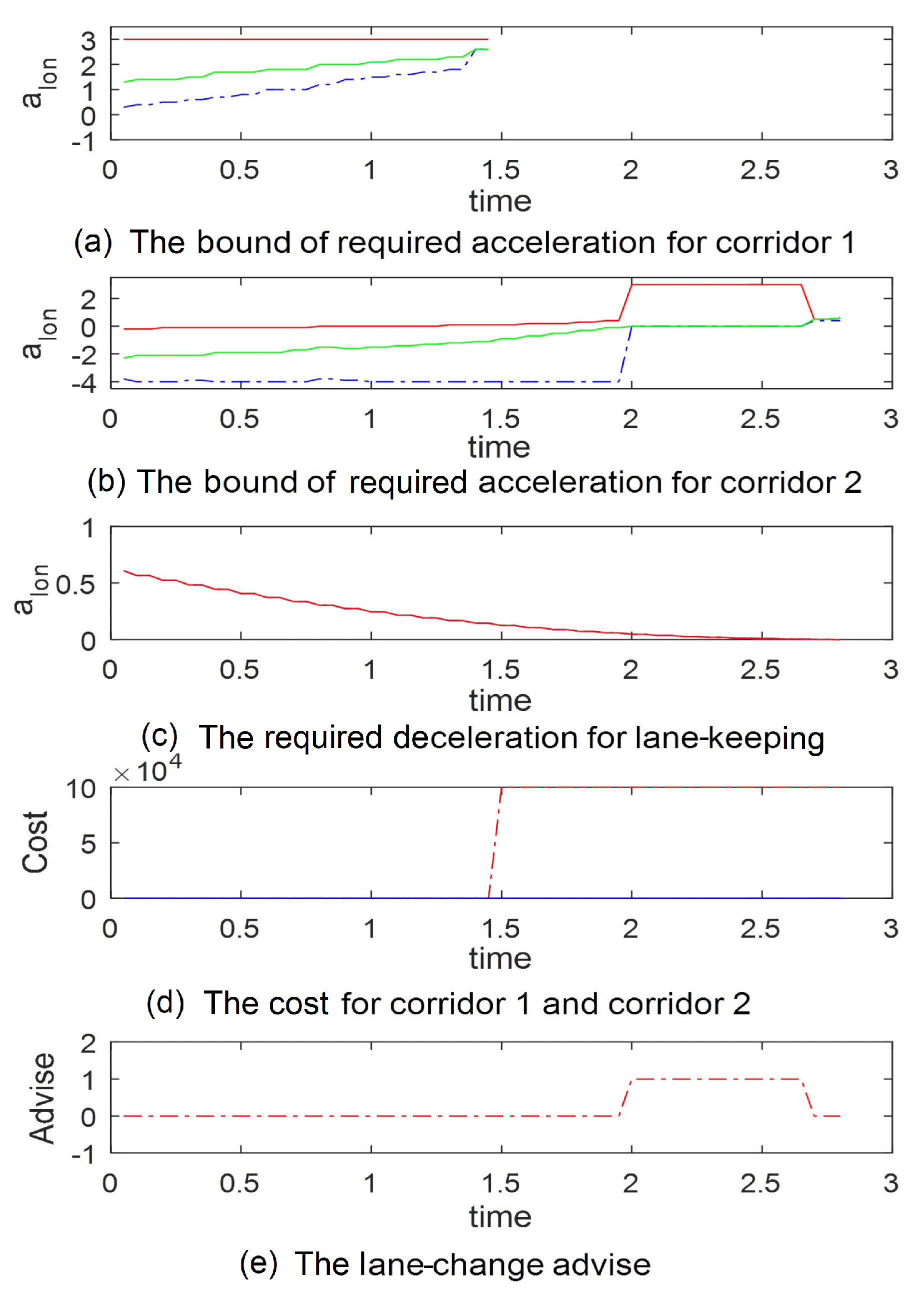
(b) = −2.5 m/s
Figure 12 shows the simulation results when the host vehicle moves forward at a constant acceleration of −2.5 m/s.
For corridor 1, as shown in Figure 12a, the algorithm suggests that the host vehicle should speed up. As the host vehicle decelerates, the cost for lane keeping in corridor 1 increases until corridor 1 is infeasible after 1.5 s, the cost of which is shown in Figure 12c. For corridor 2, the algorithm recommends that the vehicle should slow down to gain enough space for a lane-change. From 2 to 2.7 s, the host vehicle can start changing lane (Figure 12b). Within the simulation time, the lane-change maneuver is advised from 2 to 2.7 s (Figure 12e). For corridor 3, the required deceleration decreases as the host vehicle moves forward.
(c) = 2 m/s
Figure 13 shows the simulation results when the host vehicle moves forward at a constant acceleration of 2 m/s.
For corridor 1, as shown in Figure 13a, the algorithm suggests that the host vehicle should accelerate with a small acceleration from the beginning to 0.7 s. Then, the space to front vehicle decreases, the algorithm suggests that the vehicle should decelerate to maintain safe distance to the front vehicle until 1.4 s. After 1.4 s, the safety constraints to initiate a lane-change maneuver are not satisfied, and corridor 1 is infeasible (Figure 13d). From 0.7 s to 1.4 s, the host vehicle is recommended to perform a lane-change maneuver for corridor 1, as shown in Figure 13e. For corridor 2, the algorithm suggests that the host vehicle should decelerate until the lane-change maneuver is infeasible after 1.4 s (Figure 13b). After 1.4 s, safety constraints to initiate a lane-change maneuver for corridor 2 are not satisfied. For corridor 3, the required deceleration increases as the host vehicle accelerates (Figure 13c).
5.2. Driving Maneuver Evaluation during the Lane-Change Process
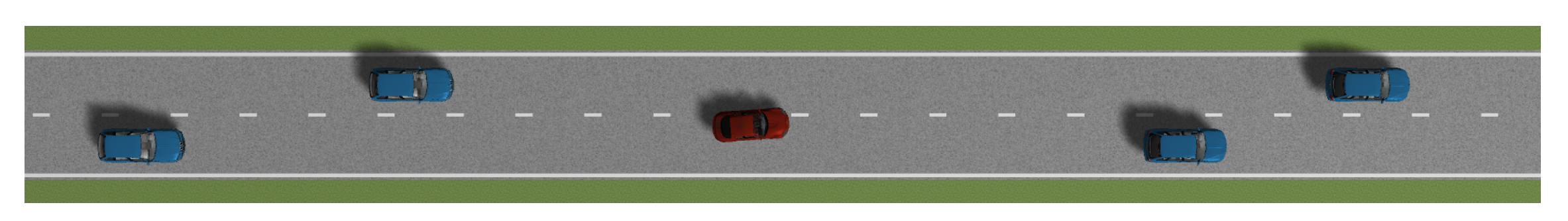
In this paper, a simulation experiment is carried out to evaluate the candidate driving maneuvers during the lane-change process. As shown in Figure 14, the host vehicle crosses the lane line towards the left lane. The parameters for the simulation are shown in Table 3.
The speed of the vehicles in the left lane is higher than that of the vehicles in the right lane. The host vehicle crosses the lane line. The other traffic participants move at a constant speed. The host vehicle has two candidate driving maneuvers, including continuing lane change and canceling lane change. The proposed maneuver evaluation algorithm can evaluate the feasibility of the two driving maneuvers. The code is implemented in C++ using Intel I7-10750 cpu running at 3.9 GHz, the average total time used is about 5 ms.
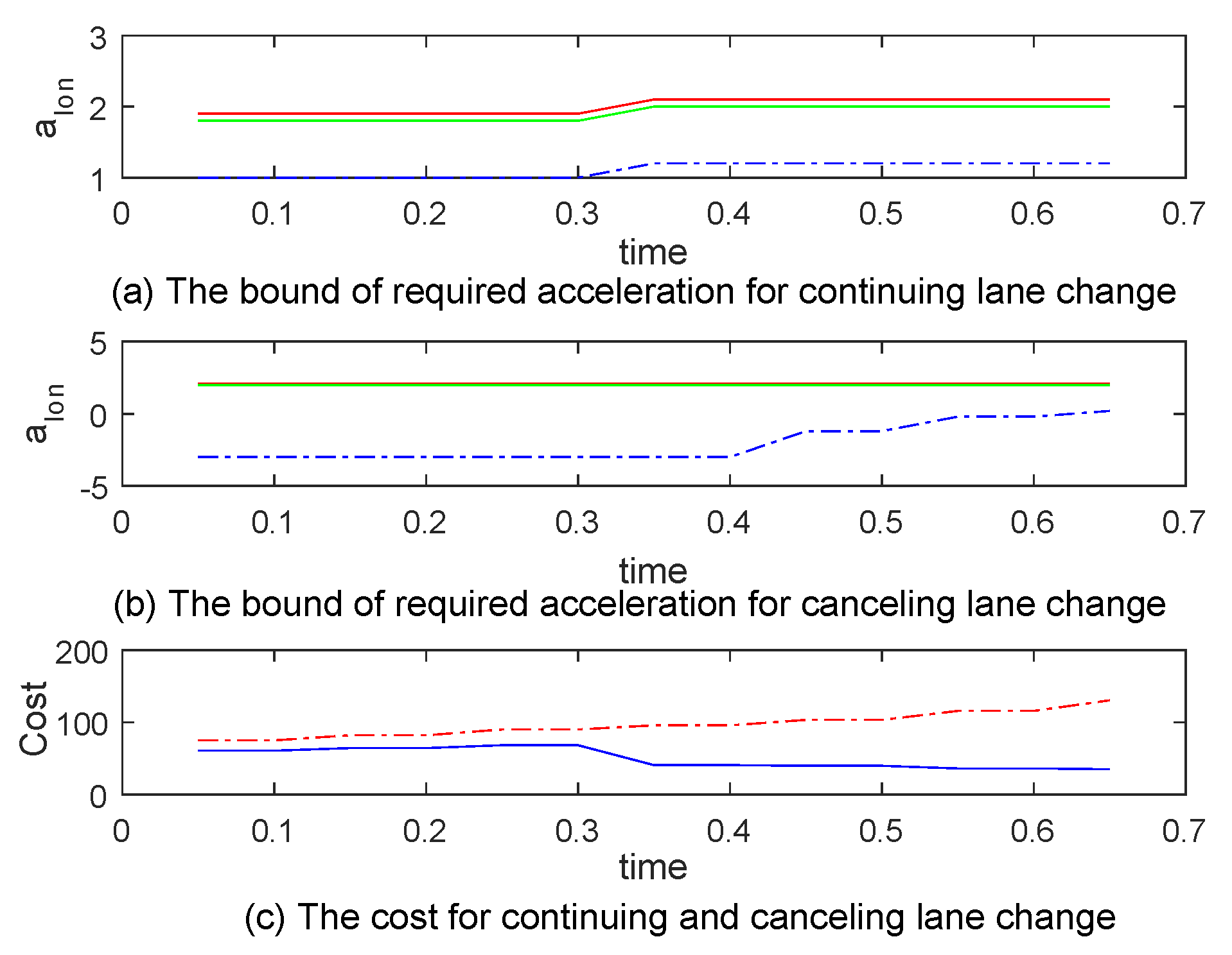
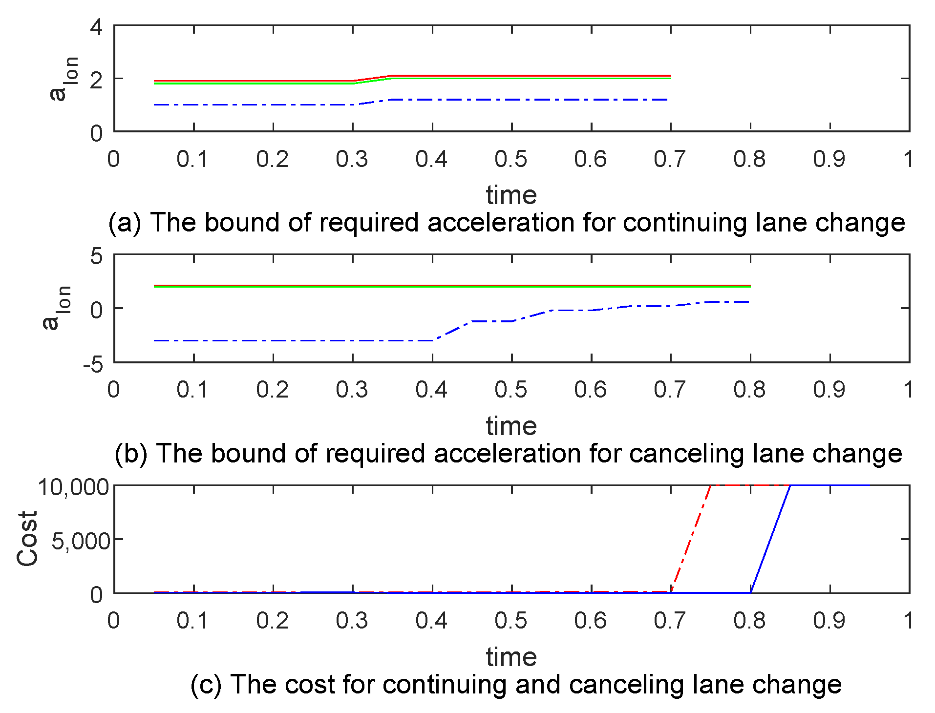
Figure 15 and Figure 16 show the simulation results at 0.65 and 0.95 s when the host vehicle moves forward at a constant speed. In Figure 15a,b and Figure 16a,b, the solid red line represents the maximum safe longitudinal acceleration, the dashed blue line represents the minimum safe longitudinal acceleration, and the solid green line represents the recommended longitudinal acceleration with the lowest cost. In Figure 15c and Figure 16c, the solid blue line represents the cost of canceling lane change, and the dashed red line represents the cost of continuing lane change.
As shown in Figure 15a, since the speed of the vehicles in the left lane is higher than that of the host vehicle, if the host vehicle continues to change lanes, the algorithm suggests that the vehicle should accelerate. The maximum acceleration is constrained by the motion limitation and the safe distance to the front vehicle in both lanes. As shown in Figure 15b, for the canceling lane-change driving maneuver, since the speed of the rear vehicle in the left lane is higher, the minimum required acceleration increases as the rear vehicle approaches. As shown in Figure 15c, both canceling and continuing lane change are feasible before 0.65 s, and the cost of canceling lane change is lower than that of continuing lane change.
As shown in Figure 16c, the continuing lane-change maneuver is infeasible after 0.7 s since the rear vehicle is too close, and it is too late for the host vehicle to speed up to continue lane-change. The canceling lane-change maneuver is infeasible after 0.8 s since the rear vehicle is too close. At 0.7 s, the for adjusting the heading angle to be parallel to the lane line is 0.89 s, and the time for the lane-change motion model to arrive at the critical lateral position is 1.6 s. Therefore, the total required time is about 2.5 s for the host vehicle to avoid the restriction of the rear vehicle. The scene of the critical position to avoid the rear vehicle is shown in Figure 8b. The velocity of the left rear vehicle is higher than that of the host vehicle. Since the acceleration of the host vehicle is limited, at 0.7 s, the longitudinal distance between the host vehicle and the left rear vehicle is not sufficient to at the position shown in Figure 8b. It is not safe to cancel lane change in the predefined range of acceleration.
6. Conclusions
In this paper, a maneuver evaluation algorithm for lane-change assistance system is proposed. According to the relative position of surrounding vehicles in the lane frame, the candidate driving corridors at the decision level are obtained. The computing efficiency is improved by eliminating the inappropriate driving maneuvers according to the limitation of motion and the basic spatial-temporal constraints. The remaining candidate driving maneuvers corresponding to the driving corridors are quantified and evaluated. A function for quantifying the driving maneuvers is proposed. The hard constraint of safety distance combined with the soft constraint that suggests that the vehicle should not interfere with the normal driving of other vehicles is taken into consideration. The proposed algorithm is validated via simulation environments in the Prescan. The experimental results show the ability of the proposed algorithm to efficiently analyze the safety of candidate driving maneuvers and evaluate the cost of each candidate driving maneuver. Suggestions regarding the speed adjustment strategy and lane-change timing for the lane-change maneuver are provided. For the tested scenarios, the average computation time is about 5 ms. The method proposed in this paper can be used in real-time applications. In future work, we will continue to study decision-making in more complex traffic scenarios.
Author Contributions
Conceptualization, algorithms, software, writing—original draft preparation, B.J.; methodology, B.J., X.L.; Writing—review & editing, X.L., Y.Z. and D.L.; supervision, X.L., D.L.; Funding acquisition, X.L., D.L. All authors have read and agreed to the published version of the manuscript.
Funding
Research on key technologies and platforms for collaborative intelligence-driven auto-driving vehicles was partly funded by the Science and Technology Development Fund, Macao S.A.R (FDCT) (Project reference number 0015/2019/AKP). The research was also partly funded by the Natural Science Foundation of Hunan Province of China under Grant 2019JJ50738.
Data Availability Statement
Not applicable.
Acknowledgments
The authors gratefully acknowledge the insightful comments of Xinglong Zhang. The authors would also like to thank the anonymous reviewers for providing constructive comments.
Conflicts of Interest
The authors declare no conflict of interest. The funders had no role in the design of the study; in the collection, analyses, or interpretation of data; in the writing of the manuscript; or in the decision to publish the results.
References
- On-Road Automated Vehicle Standards Committee. Taxonomy and definitions for terms related to on-road motor vehicle automated driving systems. SAE Stand. J 2014, 3016, 1–16. [Google Scholar]
- Dikmen, M.; Burns, C.M. Autonomous driving in the real world: Experiences with tesla autopilot and summon. In Proceedings of the 8th International Conference on Automotive User Interfaces and Interactive Vehicular Applications, Ann Arbor, MI, USA, 24–26 October 2016; pp. 225–228. [Google Scholar]
- Bevly, D.; Martin, S. Navigation in Advanced Driver Assistance Systems and Automated Driving. In Position, Navigation, and Timing Technologies in the 21st Century: Integrated Satellite Navigation, Sensor Systems, and Civil Applications; Wiley: Hoboken, NJ, USA, 2020; pp. 1769–1809. [Google Scholar]
- Tao, J.; Klueck, F.; Felbinger, H.; Nica, M.; Zieher, F.; Wolf, C.; Wang, C. Automated Test Case Generation and Virtual Assessment Framework for UN Regulation on Automated Lane Keeping Systems. In Proceedings of the SAE WCX Digital Summit, Warrendale, PA, USA, 16–18 June 2020. [Google Scholar]
- Erlien, S.M.; Fujita, S.; Gerdes, J.C. Shared steering control using safe envelopes for obstacle avoidance and vehicle stability. IEEE Trans. Intell. Transp. Syst. 2016, 17, 441–451. [Google Scholar] [CrossRef]
- Yan, F.; Eilers, M.; Lüdtke, A.; Baumann, M. Developing a model of driver’s uncertainty in lane change situations for trustworthy lane change decision aid systems. In Proceedings of the 2016 IEEE Intelligent Vehicles Symposium (IV), Gothenburg, Sweden, 19–22 June 2016; pp. 406–411. [Google Scholar]
- Koschi, M.; Althoff, M. Interaction-aware occupancy prediction of road vehicles. In Proceedings of the 2017 IEEE 20th International Conference on Intelligent Transportation Systems (ITSC), Yokohama, Japan, 16–19 October 2017; pp. 1–8. [Google Scholar]
- Dagli, I.; Reichardt, D. Motivation-based approach to behavior prediction. In Proceedings of the Intelligent Vehicle Symposium, Versailles, France, 17–21 June 2002; Volume 1, pp. 227–233. [Google Scholar]
- Ahmad, B.I.; Murphy, J.K.; Langdon, P.M.; Godsill, S.J. Bayesian intent prediction in object tracking using bridging distributions. IEEE Trans. Cybern. 2018, 48, 215–227. [Google Scholar] [CrossRef]
- Lefèvre, S.; Vasquez, D.; Laugier, C. A survey on motion prediction and risk assessment for intelligent vehicles. ROBOMECH J. 2014, 1, 1. [Google Scholar] [CrossRef] [Green Version]
- Cesari, G.; Schildbach, G.; Carvalho, A.; Borrelli, F. Scenario model predictive control for lane change assistance and autonomous driving on highways. IEEE Intell. Transp. Syst. Mag. 2017, 9, 23–35. [Google Scholar] [CrossRef]
- Li, J.; Dai, B.; Li, X.; Xu, X.; Liu, D. A Dynamic Bayesian Network for Vehicle Maneuver Prediction in Highway Driving Scenarios: Framework and Verification. Electronics 2019, 8, 40. [Google Scholar] [CrossRef] [Green Version]
- Li, J.; Dai, B.; Li, X.; Li, C.; Di, Y. A real-time and predictive trajectory-generation motion planner for autonomous ground vehicles. In Proceedings of the 2017 IEEE 9th International Conference on Intelligent Human-Machine Systems and Cybernetics (IHMSC), Hangzhou, China, 26–27 August 2017; Volume 2, pp. 108–113. [Google Scholar]
- Noh, S.; Han, W.Y. Collision avoidance in on-road environment for autonomous driving. In Proceedings of the 2014 IEEE 14th International Conference on Control, Automation and Systems (ICCAS 2014), Gyeonggi-Do, Korea, 22–25 October 2014; pp. 884–889. [Google Scholar]
- Laugier, C.; Paromtchik, I.E.; Perrollaz, M.; Yong, M.; Yoder, J.D.; Tay, C.; Mekhnacha, K.; Nègre, A. Probabilistic analysis of dynamic scenes and collision risks assessment to improve driving safety. IEEE Intell. Transp. Syst. Mag. 2011, 3, 4–19. [Google Scholar] [CrossRef] [Green Version]
- Polychronopoulos, A.; Tsogas, M.; Amditis, A.; Scheunert, U.; Andreone, L.; Tango, F. Dynamic situation and threat assessment for collision warning systems: The EUCLIDE approach. In Proceedings of the IEEE Intelligent Vehicles Symposium, Parma, Italy, 14–17 June 2004; pp. 636–641. [Google Scholar]
- Polychronopoulos, A.; Tsogas, M.; Amditis, A.J.; Andreone, L. Sensor fusion for predicting vehicles’ path for collision avoidance systems. IEEE Trans. Intell. Transp. Syst. 2007, 8, 549–562. [Google Scholar] [CrossRef]
- Nilsson, J.; Ödblom, A.C.; Fredriksson, J. Worst-case analysis of automotive collision avoidance systems. IEEE Trans. Veh. Technol. 2016, 65, 1899–1911. [Google Scholar] [CrossRef]
- Kim, B.; Park, K.; Yi, K. Probabilistic threat assessment with environment description and rule-based multi-traffic prediction for integrated risk management system. IEEE Intell. Transp. Syst. Mag. 2017, 9, 8–22. [Google Scholar] [CrossRef]
- Noh, S.; An, K. Risk assessment for automatic lane change maneuvers on highways. In Proceedings of the 2017 IEEE International Conference on Robotics and Automation (ICRA), Singapore, 29 May–3 June 2017; pp. 247–254. [Google Scholar]
- Shin, D.; Kim, B.; Yi, K.; Carvalho, A.; Borrelli, F. Human-Centered Risk Assessment of an Automated Vehicle Using Vehicular Wireless Communication. IEEE Trans. Intell. Transp. Syst. 2018, 20, 667–681. [Google Scholar] [CrossRef]
- Pek, C.; Zahn, P.; Althoff, M. Verifying the safety of lane change maneuvers of self-driving vehicles based on formalized traffic rules. In Proceedings of the 2017 IEEE Intelligent Vehicles Symposium (IV), Los Angeles, CA, USA, 11–14 June 2017; pp. 1477–1483. [Google Scholar]
- Hilscher, M.; Linker, S.; Olderog, E.R. Proving Safety of Traffic Manoeuvres on Country Roads. In Theories of Programming and Formal Methods; Springer: Berlin/Heidelberg, Germany, 2013; Volume 8051, pp. 196–212. [Google Scholar]
- Hallerbach, S.; Xia, Y.; Eberle, U.; Köster, F. Simulation-Based Identification of Critical Scenarios for Cooperative and Automated Vehicles. SAE Int. J. Connect. Autom. Veh. 2018, 1, 93–106. [Google Scholar] [CrossRef]
- Mariani, R. An overview of autonomous vehicles safety. In Proceedings of the 2018 IEEE International Reliability Physics Symposium (IRPS), Burlingame, CA, USA, 11–15 March 2018; p. 6A-1. [Google Scholar]
- Jula, H.; Kosmatopoulos, E.B.; Ioannou, P.A. Collision avoidance analysis for lane changing and merging. IEEE Trans. Veh. Technol. 2000, 49, 2295–2308. [Google Scholar] [CrossRef] [Green Version]
- Simcenter Prescan. Available online: https://tass.plm.automation.siemens.com/prescan/.
Figure 1.
The framework of the proposed maneuver evaluation algorithm.

Figure 2.
The candidate driving maneuvers in the double-lane traffic scenario.

Figure 3.
The phases decomposition for lane change.

Figure 4.
The three stages of the lane-change process.

Figure 5.
The position of the host vehicle in the lane frame.

Figure 6.
The critical lateral position for the left lane-change scenario.

Figure 7.
The phases decomposition for canceling lane change.

Figure 8.
The critical lateral position for the right lane-change scenario.

Figure 9.
The S-T graph for the double lane traffic scenario.

Figure 10.
The traffic scenario of preparing for lane change.

Figure 11.
The maneuver evaluation result with = 0.

Figure 12.
The maneuver evaluation result with = −2.5 m/s.

Figure 13.
The maneuver evaluation result with = 2 m/s.

Figure 14.
The traffic scenario during the lane-change process.

Figure 15.
The maneuver evaluation result at 0.65 s with = 0.

Figure 16.
The maneuver evaluation result at 0.95 s with = 0.


Table 1.
The motion limits.
| Kinematic Constraints | Description |
|---|---|
| Maximum lateral acceleration | |
| Maximum longitudinal acceleration | |
| Minimum longitudinal acceleration | |
| Maximum longitudinal speed | |
| Minimum longitudinal speed |
Table 2.
The simulation configuration.
| Parameter | Value |
|---|---|
| The initial velocity of the host vehicle | 40 km/h |
| The velocity of other vehicles on the right lane | 30 km/h |
| The velocity of other vehicles on the left lane | 36 km/h |
| Threshold | 2 s |
| 3 m/s | |
| −4 m/s | |
| 100 km/h | |
| 0 km/h | |
| 5 s |
Table 3.
The simulation configuration.
| Parameter | Value |
|---|---|
| The initial velocity of the host vehicle | 36 km/h |
| The velocity of other vehicles in the right lane | 36 km/h |
| The velocity of other vehicles in the left lane | 54 km/h |
| 3 m/s | |
| −4 m/s | |
| 100 km/h | |
| 0 km/h | |
| 5 s |
Publisher’s Note: MDPI stays neutral with regard to jurisdictional claims in published maps and institutional affiliations. |
© 2021 by the authors. Licensee MDPI, Basel, Switzerland. This article is an open access article distributed under the terms and conditions of the Creative Commons Attribution (CC BY) license (http://creativecommons.org/licenses/by/4.0/).
Share and Cite
MDPI and ACS Style
Jiang, B.; Li, X.; Zeng, Y.; Liu, D. A Maneuver Evaluation Algorithm for Lane-Change Assistance System. Electronics 2021, 10, 774. https://0-doi-org.brum.beds.ac.uk/10.3390/electronics10070774
AMA Style
Jiang B, Li X, Zeng Y, Liu D. A Maneuver Evaluation Algorithm for Lane-Change Assistance System. Electronics. 2021; 10(7):774. https://0-doi-org.brum.beds.ac.uk/10.3390/electronics10070774
Chicago/Turabian StyleJiang, Bohan, Xiaohui Li, Yujun Zeng, and Daxue Liu. 2021. "A Maneuver Evaluation Algorithm for Lane-Change Assistance System" Electronics 10, no. 7: 774. https://0-doi-org.brum.beds.ac.uk/10.3390/electronics10070774
Note that from the first issue of 2016, this journal uses article numbers instead of page numbers. See further details here.