
Multilink Internet-of-Things Sensor Communication Based on Bluetooth Low Energy Considering Scalability


School of IT Convergence Software Engineering, Korea University of Technology and Education, Cheonan 31253, Korea
*
Author to whom correspondence should be addressed.
Electronics 2021, 10(19), 2335; https://0-doi-org.brum.beds.ac.uk/10.3390/electronics10192335
Submission received: 8 September 2021
/
Revised: 18 September 2021
/
Accepted: 21 September 2021
/
Published: 23 September 2021
(This article belongs to the Special Issue IoT, Edge Computing and AI: Enabling Emerging Intelligent Applications)
Abstract
:As the growth rate of the internet-of-things (IoT) sensor market is expected to exceed 30%, a technology that can easily collect and processing a large number of various types of sensor data is gradually required. However, conventional multilink IoT sensor communication based on Bluetooth low energy (BLE) enables only the processing of up to 19 peripheral nodes per central device. This study suggested an alternative to increasing the number of IoT sensor nodes while minimizing the addition of a central processor by expanding the number of peripheral nodes that can be processed per central device through a new group-switching algorithm based on Bluetooth low energy (BLE). Furthermore, this involves verifying the relevancy of application to the industry field. This device environment lowered the possibility of data errors and equipment troubles due to communication interference between central processors, which is a critical advantage when applying it to industry. The scalability and various benefits of a group-switching algorithm are expected to help accelerate various services via the application of BLE 5 wireless communication by innovatively improving the constraint of accessing up to 19 nodes per central device in the conventional multilink IoT sensor communication.
1. Introduction
In the industrial field, wired communication is predominantly used in communication between devices. The data of sensors located in a lower system of communication layer are transferred using the 420-mA analog output of sensors and serial communication such as RS-485. These collected data are transferred to the upper system of communication layer through ethernet communication or field-bus communication for monitoring and equipment control [1]. Such wired communication, such as serial, ethernet, and field-bus communication, sends electrical or optical signals via physical media and enables stable data communication after installation owing to its high security and stability. However, its process complexity is high owing to the installation work during the initial equipment manufacturing process; it is also associated with high uncertainty of material procurement. Moreover, after the initial equipment setup, expanding or changing the equipment incurs a high cost and increases the risk because of complicated cable entanglement. Additionally, the possibility of fire or trouble due to the contamination or damage of cables is higher. In particular, when the number of pieces of equipment is increased, the relocation or modification of the wiring work causes many difficulties, such as lengthy service suspension [2].
Therefore, investments in equipment based on the internet of things (IoT) using wireless communication have been accelerating recently [3]. For this reason, the wireless communication required in the industrial field should be easier to collect multiple sensor data, have less radio wave interference, have better security, should not require complicated procedures for the access of wireless communication, and have easier maintenance. Representative wireless network technologies mainly used in industries include wireless fidelity (Wi-Fi), Bluetooth, and ZigBee. Among these, Bluetooth is being utilized most widely in industries owing to features such as compact device size, low power consumption, and fewer effects of physical environmental factors [4]. With the beginning of full-scale utilization of Bluetooth, Bluetooth low energy (BLE) has been applied since 2010 [3]. In 2016, the BLE 5.0 standard was released; it doubled the transmission speed and increased the transmission range and data bandwidth by four and eight times, respectively, compared to those in the case of the BLE 4.x standard [3,5].
For the utilization of Bluetooth communication in the industry, data collection through multiple BLE devices is required. Accordingly, the method of a mesh topology supported by the BLE 5. x standard and BLE multi-link communication can be utilized. By this method, it’s possible to configure a wireless network that can control multiple BLE devices simultaneously, but since the mesh topology has capacity restrictions (payload per packet is 11 bytes), a multi-link is required to transmit and receive a lot of data at once. Using multi-link, IoT sensor data can be collected based on the wireless network in the facility. Multi-link communication supported by Nordic nRF52 Soft Device can connect up to 19 peripheral devices to one central device [6]. This is a 1:19 multi-link BLE communication method in which 20 devices can communicate at the same time. However, since BLE multi-link communication has a limitation that a maximum of 20 devices can be connected, it is inevitable to get an additional investment in BLE equipment when the number of IoT nodes that one central device can control exceeds 20 [7,8].
Meanwhile, the IoT sensor market in 2021 is expected to grow by 20–30% compared to the existing size [9].
In the free field environment, the general BLE 5.x transmission distance is 65 m based on Transmitter Power 0dBm, but this numerical value may change depending on the position of the antenna and dBm.
Although it varies depending on the position and dBm of the antenna, the general transmission range of Bluetooth 5.x in a free field environment is 65 m based on 0 dBm [10,11]. Thus, factory automation and large-scale equipment require many BLE devices and antennas. This is a main factor that increases interference between BLE devices [12], thus causing errors in IoT sensor data and equipment troubles. To connect various IoT nodes to one BLE device while minimizing such troubles requires a fundamental scalability technology that can solve the current limitation of 19 nodes.
Therefore, this paper applied the BLE 5.x Stack structure in this study to efficiently collect data due to the increase in various sensors in the industrial field, and to minimize the loss of unnecessary wiring from the installation of the sensor. This study proposes multi-link IoT Sensor Communication based on a new group switching algorithm that can maximize node scalability for one BLE device.
This guarantees the scalability of multilink BLE communication through BLE peripheral processors that are grouped with a BLE central processor. Additionally, to facilitate service management, a user interface application that enables sensor monitoring is provided. This study will increase the communication scalability of the multilink method and help accelerate the application of BLE IoT services to industries. Moreover, the findings of this study will help achieve efficient and economic management and maintenance of automation equipment.
2. Theoretical Background
2.1. Bluetooth 5.3
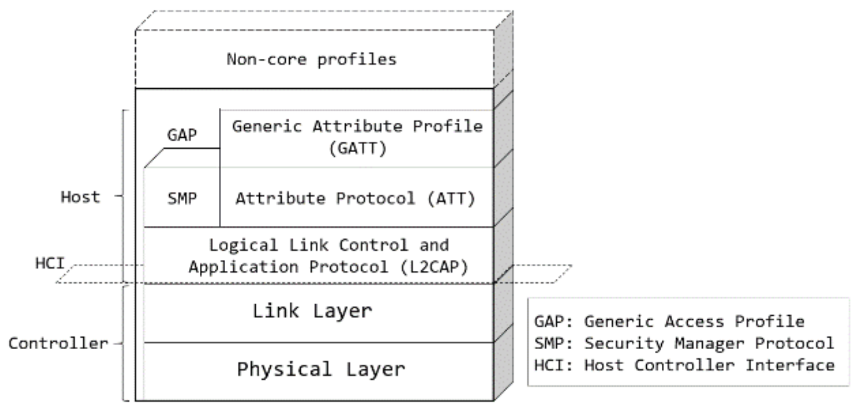
BLE is a leading new wireless technology developed by the Bluetooth Special Interest Group (SIG) for short-distance low-power communication [1,2], and Bluetooth revisions have been introduced to enable inter-device short-distance control and application monitoring [13]. The original design of the BLE is focused on star topology networking, which limits the network application scope and excludes end-to-end path diversity [13]. Figure 1 illustrates the architecture of BLE 5.3, which is the basis of this study [14].
Figure 1 shows the BLE protocol stack and its two main parts, i.e., the controller and the host. The controller comprises the physical layer and the link layer and is typically implemented as a small system on chip (SOC) with an integrated radio [15].
The host runs on an application processor and includes upper-layer functionality, including logical link control and adaptation protocol, attribute protocol (ATT), generic attribute profile (GATT), security manager protocol, and generic access profile (GAP) [15]. Communication between the host and the controller is standardized in the host controller interface. Finally, non-core profiles (i.e., application-layer functionality not defined by the Bluetooth specification) can be used on top of the host [15].
The BLE GAP takes charge of the connection with advertising in Bluetooth and the core roles involving the peripheral and central processors. The peripheral processor periodically collects and transmits IoT sensor data, whereas the central processor only searches signals and collects data satisfying the standard [1,16].
As the latest release of a wireless IoT technology announced in July 2021, BLE 5.3 118 supports ubiquitousness and global interoperability for all types of digital devices has improved in its coverage and data speed when compared with the 4 multiplied by 120 version and supports advertising channel method [16]. Furthermore, it supports the advertising channel method [17]. This method can separately define and increase the capacity for two types of primary and secondary advertising channels [13]. Primary advertising channels are the same three advertising channels available in older BLE versions, whereas secondary advertising channels use the remaining 37 BLE channels (formerly defined solely as data channels). Note that secondary advertising channels exploit frequency hopping such as data channels in any BLE version [13,17,18]. In particular, BLE 5.3 has improved major features for application developers as well as for the protocol, such as wireless stability and reliability, energy efficiency, and user experience [17].
The BLE has a broadcaster, observer, central, and peripheral modes. Among these, the central and peripheral modes allow multiple access for up to 19 nodes because they support the BLE multilink method. In particular, the master device has advantages in security because it works privately when connected, and the master specifies the access target through the UUID and NAME. Furthermore, it enables the collection and monitoring of sensor data. A BLE SoC that supports multi-link, basically consists of 1 central device and 19 peripheral devices, enabling simultaneous connection of 20 devices.
With this new Bluetooth 5.3 feature, when there are no changes in the advertisement data, unnecessary processing occurs on the nodes. Therefore, it reduces the overall throughput [17]. The AdvDataInfo (ADI) field in the packet header indicates whether the payload data have been changed in any of the periodic advertising packets [17]. If there are no changes, the node drops the subsequent packets in the chain and uses the time to process other receive transactions [17]. The ADI in periodic advertising increases the overall Bluetooth network efficiency and reliability, saves processing capacity on the nodes, reduces node power consumption, and gives more time for scanning in primary channels [17]. Additionally, the alternate Media Access Control (MAC) and PHY (AMP) feature has been removed [18].
2.2. Related Works
Based on recent research, the chart above is classified into several categories: improvement of BLE communication architecture, reinforcement of data collection performance, enhancement of security, and application research using BLE technology, etc. First, we will go through recent studies and major issues related to BLE communication architecture.
Basu et al. [19] conducted experiments to combine the IoT (NB-IoT) and BLE technology (lightweight machine to machine/constrained application protocol (LwM2M/CoAP) protocol stack) to analyze various transmission modes that can occur in communication when complex and diverse wireless IoT technologies are combined; security problems as well as the impact of handover between both communication technologies are also analyzed. As a solution to these issues, they developed a prototype to suggest an end-to-end architecture that is suitable for multimode communication. In particular, they conducted in-depth research focusing on the evaluation of waiting time for handover. In particular, this study conducted an in-depth evaluation focusing on the waiting time for handover. This contributes to the improvement of performance within the gateway range. Ryu et al. [4] developed a Raspberry Pi board gateway and an Arduino board-based BLE sensor module and transmitted the data generated in multiple BLE sensor modules to the server or cloud. However, it was difficult to collect data in real time (owing to the limited usage time which used the power battery of the BLE sensor module) and to manage products because the BLE sensor modules were identified only through the IDs. In addition, scalability evaluation is required by calculating the number of BLE sensors as seven. Garcia-Espinosa et al. [20] proposed to measure the current consumption of four BLE commercial platform boards composed of central and peripheral devices, and to use it as a design guideline for developers to implement an optimal application. Badihi et al. [21] analyzed the functions and performance of BLE 5.0, such as communication coverage, communication speed, advertising capacity, and channel selection algorithm, through a data-transfer experiment according to LE2M PHY and LE1M PHY. Although BLE reception strength indicator (RSSI) and indoor environment throughput verification were performed indoors, there was no attempt for BLE scalability evaluation considering capacity.
Studies related to enhancing data collection performance using BLE were also looked at.
Nouali et al. [22] conducted experiments on efficient data collection in the IoT environment by building a system using an Arduino board and Android mobile environment, but the distance between the data sensor unit and the gateway was only 6 m. Due to the short distance of 6m between the data sensor and the gateway, there is a limitation for industrial use, and it is also difficult to use multiple communication based on a mobile environment. Vance et al. [23] continued research on the possibility of an efficient data collection method by inferring user context using only Bluetooth that receives the signal strength of a smart device. Lee et al. [24] built a BLE ad hoc network composed of group communication modules between drones and IoT devices and conducted communication tests between group communication modules and IoT devices. Fourati and Said et al. [25] suggested that the BLE communication of the RHMS is widely used to discover physiological symptoms through different modes and multiple detections and described in detail the various steps required for the Android system to control sensors and activate BLE communication. The conversion to embedded systems has some difficulties because it is limited to mobile application systems. Ayele et al. [26] proposed a dual wireless IoT network architecture to monitor wild animals, which collected data through IoT BLE communication and gathered these to the cluster head through the low-power wide-area network (LPWAN). This has limits in real-time and also restricts the group’s expansion because of its focus on ultra-low-power IoT devices.
In addition, there have been studies on strengthening the security of BLE devices.
Zuo et al. [27] raised the problem of fundamental defects in the design and implementation of communication protocol between the BLE device and accompanying mobile app, enabling accurate identification of BLE devices via fingerprints using the static BLE UUID of the app by attackers. They developed a BLE IoT device discovery app and directly verified it to overcome the security vulnerabilities of fingerprint recognition for BLE IoT devices. A BLE IoT device discovery app can be developed and verified directly, through this study, which can solve security vulnerabilities for fingerprint recognition of BLE IoT devices, but this is limited only to mobile apps. Antonioli et al. [28] proposed to mitigate downgrade attacks and implement effective legacy and a non-legacy compatible BLE security response design by testing 38 Bluetooth devices (32 unique Bluetooth chips) and 19 BLE devices using all major devices from different vendors.
On the other hand, focusing on recent research among numerous BLE technology-based application case studies, Jeong and Cho et al. [29] conducted a study on the smart factory safety management system using Bluetooth; a system was developed that monitored the safety situation by collecting data of Bluetooth sensor nodes in industrial sites with a safety management device equipped with Bluetooth functionality. Park et al. [30] analyzed acquired mobile data such as user activity and location data based on smart mobile devices via machine learning technology. Based on this, an optimization of the private parking service for each user was introduced. Assuming that museum visitors have Bluetooth Low Energy (BLE) devices, Giuliano. et al. [31] sent them the packets periodically, and presented a method for estimating the geographic location of visitors inside a museum. Demrozi et al. [32] introduced a method for estimating the number of people in a specific area by bringing a BLE-based pattern recognition model into the world that can detect cognitive changes of people based on BLE that is similar to previous Wi-Fi-based systems while reducing cost and installation effort, and raising practicality.
Table 1 summarizes the main advantages and disadvantages of related papers introduced so far.
3. Research Process
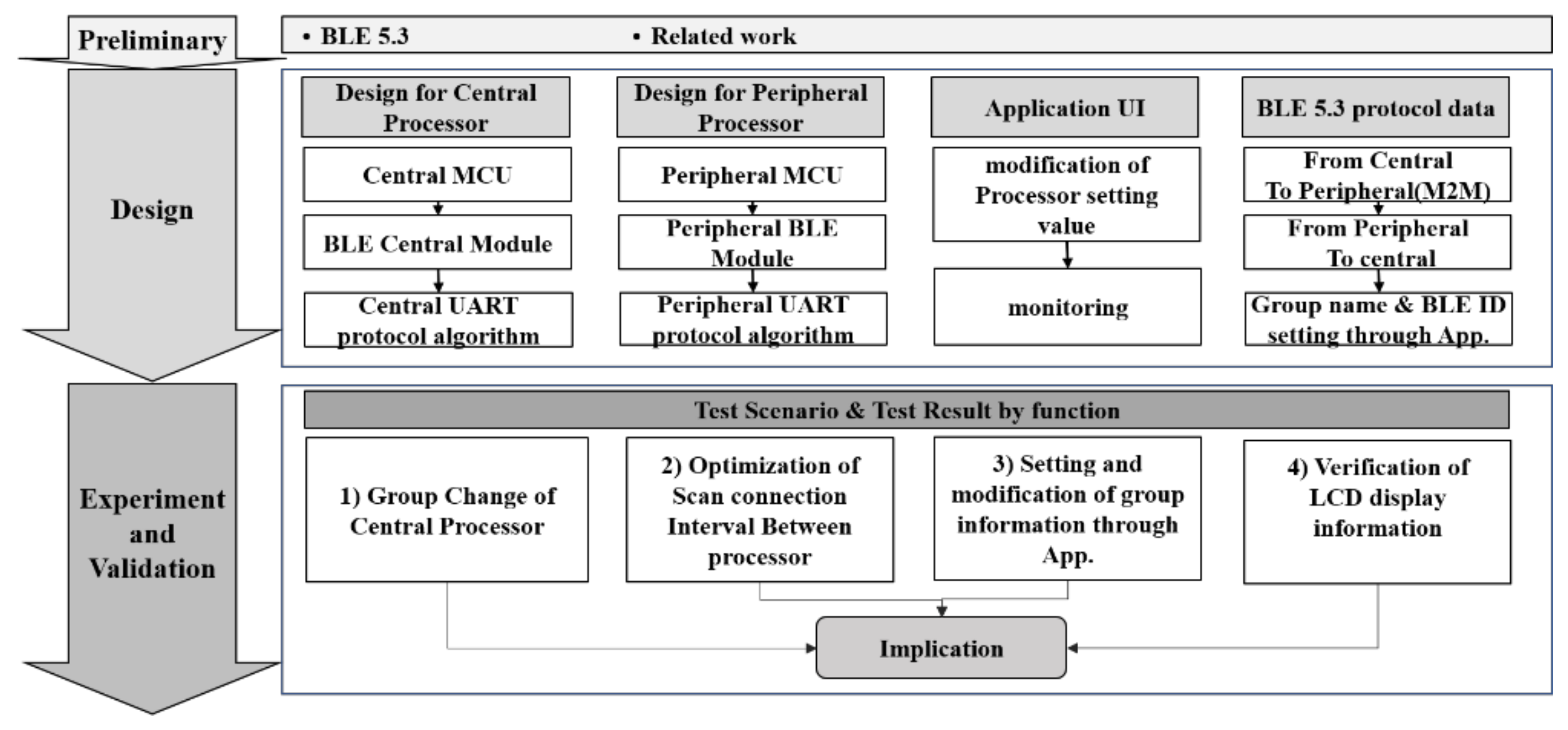
The study was progressed with the procedure shown in Figure 2 by confirming the necessity of this study via BLE 5.3 and related prior studies. After confirming the need for this study through a preliminary study related to BLE 5.3, this study was conducted, as illustrated in Figure 2, according to the following process.
First, the central and peripheral processors were designed. Then, the user application for setting and changing the group name and BLE ID were designed. Lastly, the protocol for each communication section was designed based on BLE 5.3.
Based on the completed detailed design, the accuracy and reliability of functions were verified through an experiment. After implementing the prototype, the accuracy was verified by conducting experiments on the group change function of the central processor. Additionally, optimization experiments were performed to confirm the scan connection interval setting value between processors to enable stable and reliable IoT services. Furthermore, the accuracy of the functions to set and change the group information through the application and the accuracy of real-time performance data values, including the group information display on the LCD window, were verified.
Finally, the implications of the study results are discussed based on the final experimental results.
4. Design
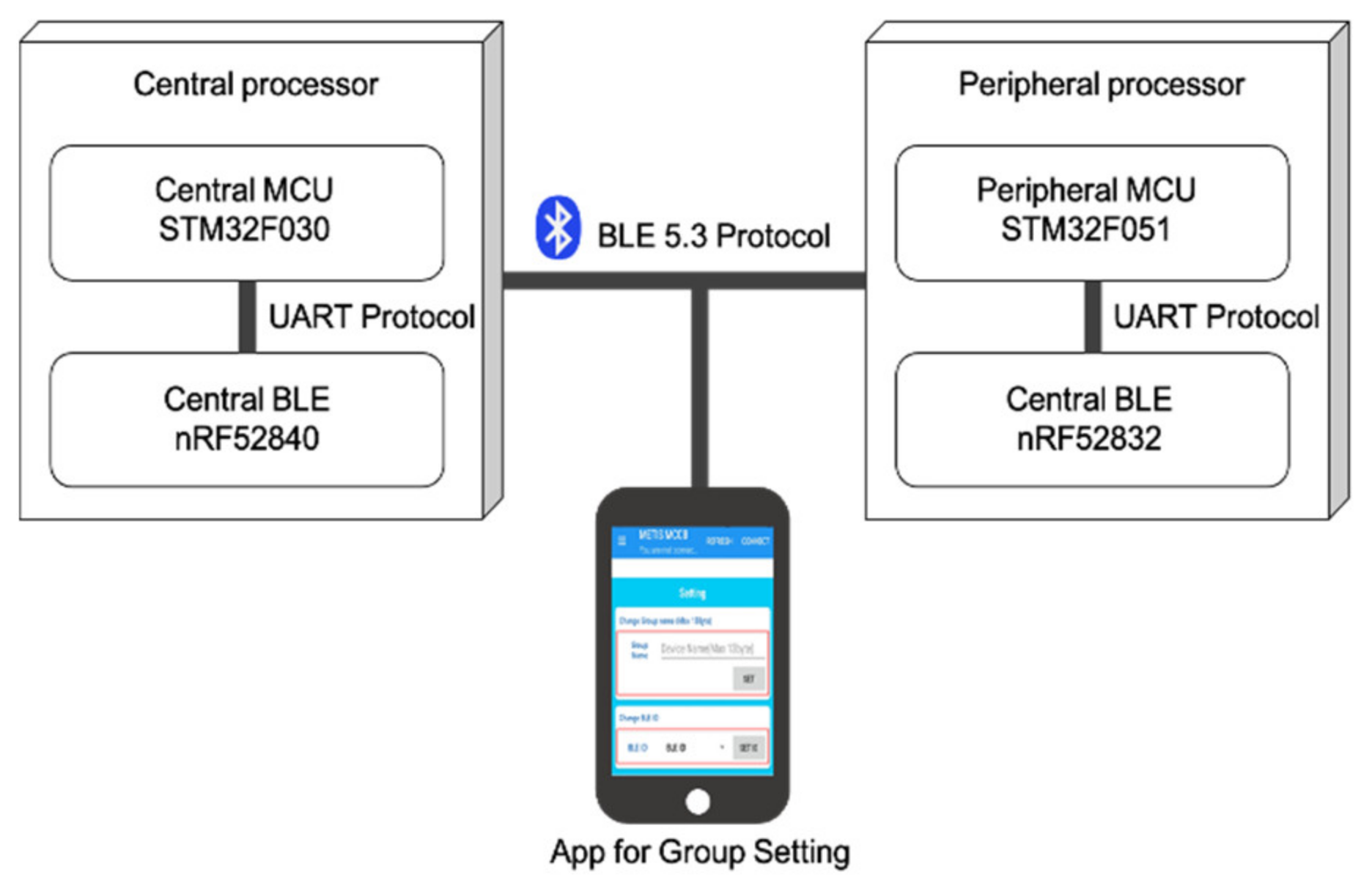
As shown in Figure 3, the central processor is a data-processing device, whereas the peripheral processor is a device for BLE IoT sensors. The BLE 5.3 protocol is used for communication between devices and the BLE ID and group name setting services through the application.
4.1. Central Processor Design
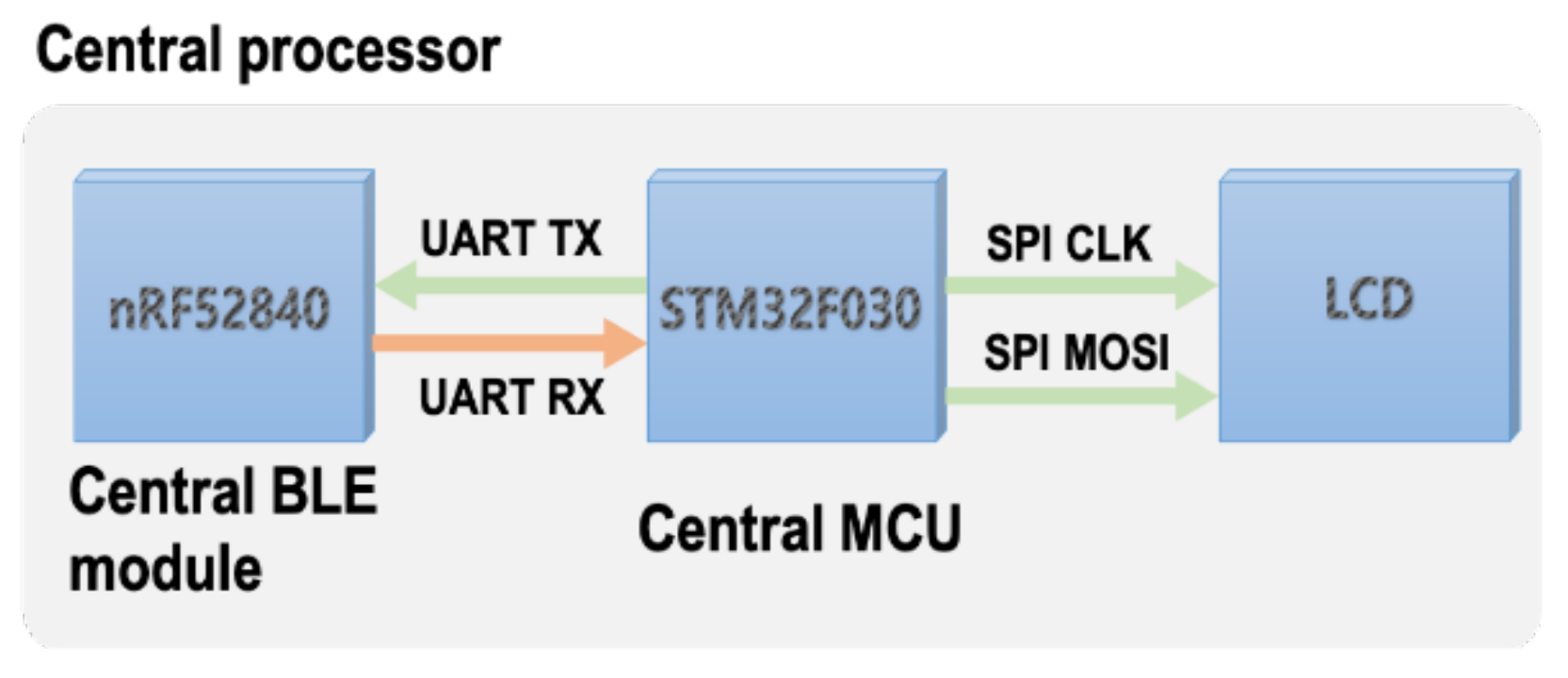
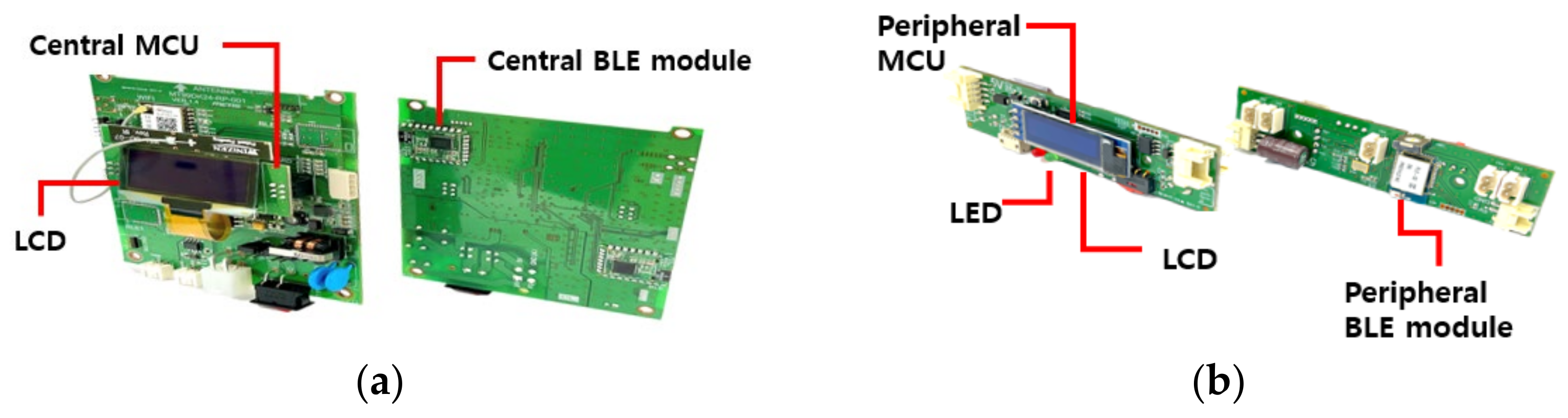
The central processor is responsible for data collection and processing and comprises the central micro controller unit (MCU) and BLE central module. It uses the universal asynchronous receiver/transmitter (UART) protocol for communication between them. For the model used in this study, ST’s STM32F030 MCU of ST and Nordic’s nRF52840 module for BLE communication were used.
As shown in Figure 4, the STM32F030 MCU and the nRF52840 module exchanged data via UART communication. The STM32F030 MCU and LCD were connected via SPI communication to monitor the BLE status.
4.1.1. Central MCU Design
The STM32F030 MCU rebooted the device by resetting the nRF52840 module for data processing. After initialization, it stood by until the group setting command was received from the STM32F030 MCU (see Figure 4). To this end, the attributes of the received data were identified through flags. These data were designed to distinguish between the group name and other data, and the group name was changed when only the group name was received.
The LCD was designed to display the ID of the central device, the currently selected group number, and the BLE ID of the peripheral processor. It was also implemented to show the data reception status and the information of the connected peripheral processor.
4.1.2. Central BLE Module Design
For the BLE central module, Nordic’s nRF52840 module was used, which had the following functions.
First, it initialized the UART setting and BLE stack. Second, it changed the group name. In other words, once the nRF52840 module received a group name and BLE ID, it changed the device name to the received group name. At this time, it had to wait until the group setting command was received from the STM32F030 MCU. Third, it scanned the BLE connection information after the BLE’s GAP, GATT, and scan settings. Fourth, the nRF52840 module received the requested data from the STM32F030 MCU and transferred the data to peripheral processors through the BLE 5.3 communication. Finally, the BLE central module received the response data of peripheral processors and transferred them to the central MCU.
To improve scalability and performance of the BLE IoT multilink communication, the flash memory capacity of the nRF52840 module had to be greater than that of the peripheral module. In this study, it was set at 1024 KB, twice the size of the peripheral module’s flash memory, and the RAM capacity was set at 256 KB, four times the size of the peripheral module’s flash memory. Therefore, the number of multilink connections here was expanded to 20 (1 central and 19 peripherals).
4.1.3. Central UART Protocol Algorithm Design
First, the header file was designed. To improve the performance, the inner parameters of the central BLE module were reset. For the nRF52840 module, the sdk_config.h file of the open source of the ble_app_multilink_central project provided by nRF52 SDK and SoftDevice S140 [33] for multilink communication of the central and peripheral processors was used. First, the values of parameters NRFX_CLOCK_CONFIG_LF_SRC, CLOCK_CONFIG_LF_SRC, and NRF_SDH_CLOCK_LF_SRC were changed from default 1 (XTAL) to 2 (Synth) to activate the clock outside the nRF52840 chip instead of the default inner clock. This measure improved the reliability of nRF52840 UART communication through X-TAL to enhance the accuracy of clock synchronization between the central MCU and central BLE module. Second, the values of the NRF_SDH_BLE_CENTRAL_LINK COUNT and NRF_SDK_TOTAL_LINK_COUNT were changed from default 8 to 20 to increase the multilink count to 20. Third, the constant values of NRF_BLE_SCAN_SCAN_INTERVAL and NRF_BLE_SCAN_SCAN_Window were redefined to 64 and 24, respectively, to set the BLE SCAN interval of the nRF52840 module to 40 ms (64 multiplied by 0.625 ms) and the SCAN holding time to 15 ms (24 multiplied by 0.625 ms). The BLE transmission time per unit is 0.625 ms [34]. Fourth, the central processor performed repeated experiments on its own to derive the optimal interval value that could send and receive a stable BLE data packet. Through this process, parameters NRF_BLE_SCAN_MIN_CONNECTION_INTER VAL and NRF_BLE_SCAN_MAX_CONNECTION_INTER VAL were input. For the parameter settings, the optimal values were derived through several empirical experiments.
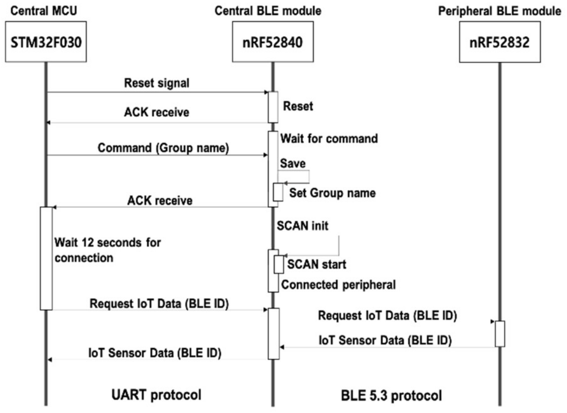
After completing the design of the header file as above, we designed the central UART protocol algorithm. To change the group of the central processor, when the STM32F030 MCU sent a reset signal to nRF52840 (see Figure 5), the nRF52840 module was reset and rebooted. After initialization, the result was sent (ACK) to the STM32F030 MCU. This process initialized every function of the nRF52840 module.
When the STM32F030 MCU sent the group name for the change, the nRF52840 MCU received this value via the parameter and changed the group number of the central processor. Once the change was completed, it notified the group change result by sending an ACK signal to the STM32F030 MCU.
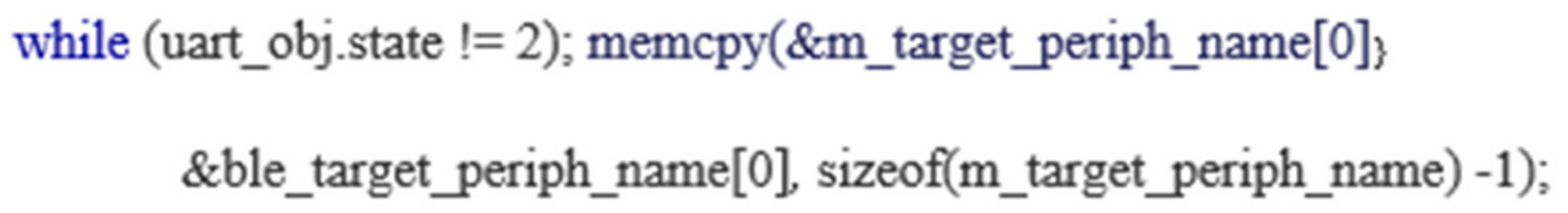
Figure 6 shows that, to examine the logic in detail, the attribute of the data received by the nRF52840 were through the variable uart_objt.state. Flag 1 indicated that the received data revealed the value of a general network well-known state that occurred in UART communication. Flag 2 indicated that the received data revealed the group name. Therefore, if a flag value of 2 was returned to the nRF52840 module on standby, the group name received by the UART was stored in ble_target_periph_name, a temporary storage place; then, this value was stored in the variable m_target_periph_name.
This variable was used for storing the group name during scanning for multilink communication with the peripheral processor.
Once the setting for BLE multilink communication was completed through this process, the nRF52840 module ran a process for scanning the data request (“Scan start”) and found peripheral processors that were set to the same group name in the surroundings and connected them. Next, the STM32F030 MCU, which had confirmed the normal completion of the central group change settings, requested the IoT sensor data from the nRF52840 module. Then, the nRF52840 module processed the request through the peripheral group set to the same group name and returned the result. Once the settings were performed by this round robin method for the entire set number of groups, the target peripheral process name returned to the group that was generated first.
4.2. Peripheral Processor
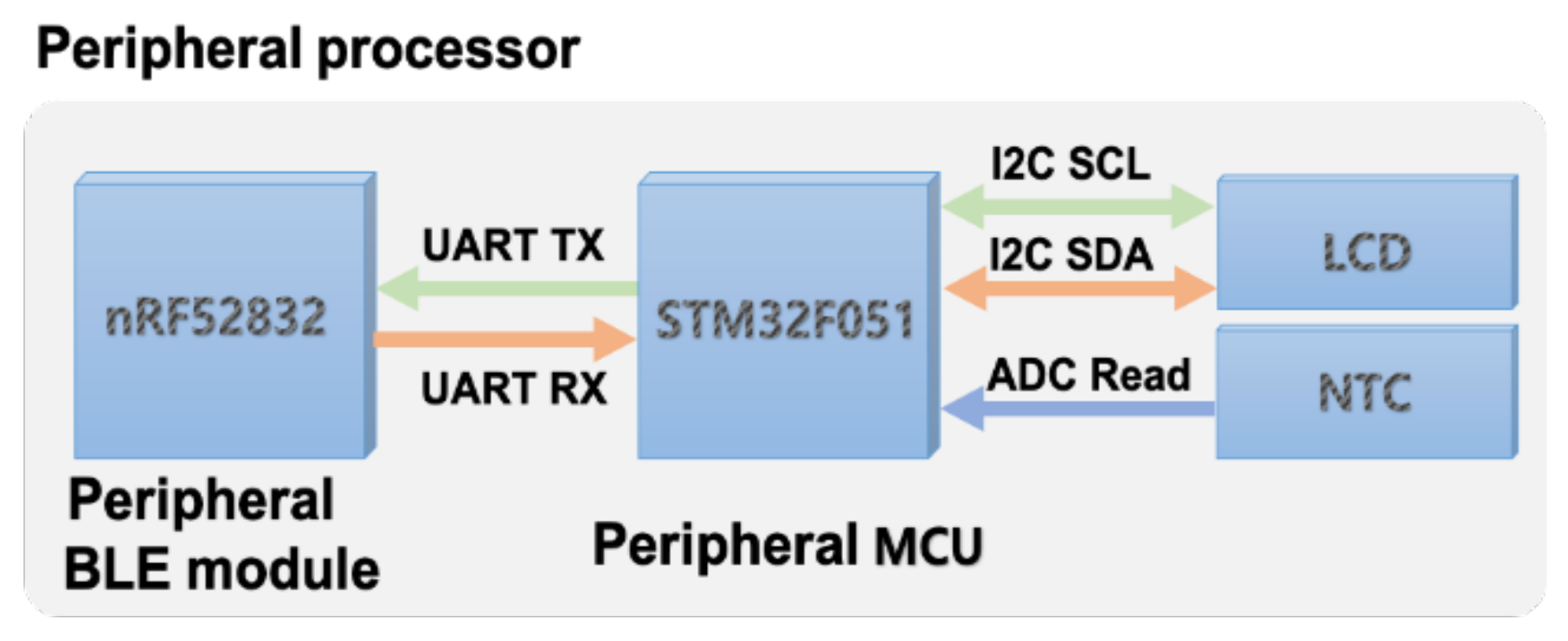
The peripheral processors for collecting and processing IoT sensor data were composed of the peripheral MCU and peripheral BLE module. The UART protocol was used for communication between them. The model used here was ST’s STM32F051 MCU, and Nordic’s nRF52832 module was used for BLE communication.
As shown in the peripheral processor block diagram in Figure 7, the data exchange between the STM32F051 MCU and the nRF52832 module was designed using the UART protocol. The I2C protocol was used for communication between the STM32F051 MCU, a peripheral MCU, and the liquid crystal display (LCD). The negative temperature coefficient (NTC), a device that was not in the central processor, was added. The NTC is a temperature-measuring sensor and is designed for the peripheral processor only. The temperature sensor was added in this study for IoT data simulation. When the central processor requested temperature sensor data for the experiment, the peripheral processor, which was on standby, sent the data through the BLE 5.3 communication.
4.2.1. Peripheral MCU Design
The STM32F051 MCU reset the nRF52832 module to process the request data and IoT sensor data from the central processor. After initialization, the control process between the STM32F051 MCU and the nRF52832 module was the same as in the control method through the central MCU design and flag.
The LCD displayed only the BLE ID and the temperature sensor data of peripheral sensors but did not display the ID of the central device; the number of the currently selected group, data reception status, and the peripheral processor were displayed on the central processor.
4.2.2. Peripheral BLE Module Design
For the peripheral BLE module, Nordic’s nRF52832 module was used. The functions of the nRF52832 module are the same as those of the nRF52840 module.
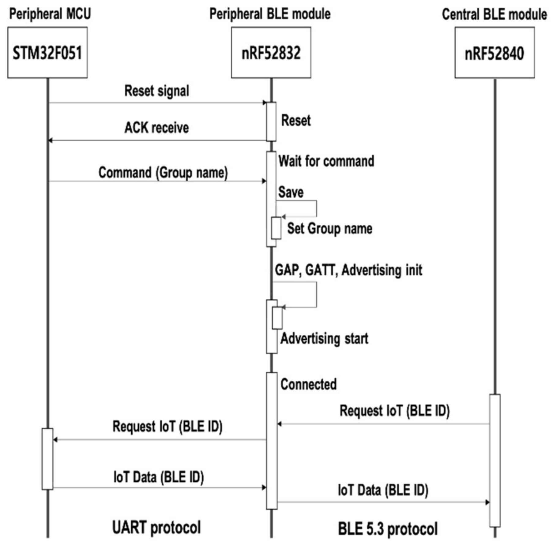
Since the peripheral BLE module did not require complex processing, using many devices of low specifications was advantageous for performance. Therefore, this study configured three sets in total with each group consisting of 19 devices using the nRF52832 module, whose flash memory and RAM capacities were only 1/2 and 1/4 of those of the nRF52840 module, respectively. Meanwhile, the control method of the nRF52832 module was similar to that of the nRF52840 module. To explain the comparison between the central BLE module and the control method, the first and second were the same as those of the nRF52840 module of 4.1.2. However, as shown in Figure 8, the peripheral BLE module plays the role of advertising the BLE connection information after setting the GAP and GATT.
The fourth nRF52832 module received a request of the central processor through the BLE 5.3 communication and bypassed it to the STM32F051 MCU. The fifth STM32F051 MCU received the requested data and transferred the temperature data to the nRF52832 module, and the transferred data were delivered to the central MCU through the BLE 5.3 communication.
4.2.3. Peripheral UART Protocol Algorithm Design
First, the header file design was performed. To improve the performance, the inner parameters of the peripheral BLE module were reset. For multilink communication between the central and peripheral processors, the nRF52832 module used the sdk_config.h file of the ble_app_uart project, an open source provided by the nRF52 SDK and SoftDevice S132 [33]. Unlike the central processor, if only the clock setting was required in the peripheral UART, the setting value was the same as that of the central processor.
Next, it designed the peripheral UART protocol algorithm. This process was the same as the group name setting of the central processor. However, since it had to be possible to change the group name setting, the parameter for device name definition provided in the open source by default had to be deleted and newly defined as a variable. Thus, the #define DEVICE_NAME parameter was deleted, and “uint8_t deviceName [15]” was defined as a new input variable to replace it. The deviceName defined here stored the group name received from the STM32F051 MCU, and the deviceName was used in the BLE GAP function.
To process this in the SDK, the sd_ble_gap_device_name_set() in the static void gap_params_init (void) function was used. Here, it was designed to enter the GAP setting value and the device name together. When the changed group name was entered, the function automatically collected the value from the system and automatically defined the GAP setting. Through this defined value, the new group name and BLE connection information were set in the nRF52832 module. The peripheral processor was used for advertising the newly set group name.
4.3. Processor Control for Application UI
4.3.1. Application UI Design for Setting Value Modification of Processor
This was the UI design of the application for changing the group name and BLE ID of the central and peripheral processors. The group names of the central and peripheral processors were unique. Typically, the group names of peripheral processors were generated in the form of {Central Processor name + NN}, where NN indicates a two-digit integer.
When the group name and BLE ID of the BLE module were entered in the “Group Name” text box in the mobile application, the central and peripheral processors identified their names, and the change process was carried out by each change process and algorithm. The BLE ID was changed by selecting from the BLE ID drop-down list box.
4.3.2. Application UI Design for Processor Monitoring
In the process described in Section 4.3.1, it had to be possible to verify the normal changes in the group names and BLE IDs of the central and peripheral processors. To that end, a monitoring menu was added and applied in the application, so that the group names and BLE IDs advertised in the peripheral processor were confirmed.
4.4. BLE 5.3 Protocol Data Design
4.4.1. Central to Peripheral (M2M) Processor Communication
When the central and peripheral processors are connected in multilink communication, the former transmits the data request protocol of 10 bytes through the connected link to the peripheral processor. Table 2 explains the test design for the central processor request. For the data request protocol, one byte of the start code was used in order to prepare for packet errors and forgery. It was invalidated if the value of Start Code 1 was different from the value of Start Code 2.
Length indicates the length from the start code to the check sum and was defined as one byte. The command was set to 0 × 00 to indicate that it was a request processing type. The ID was defined as the BLE ID of the peripheral processor, the check sum as the sum from the start code to Reserved 2, and the end code as two bytes.
4.4.2. Peripheral to Central Processor Communication
Upon receiving the requested data from the central processor, the peripheral processor transmitted twenty-byte sensor data to the central processor.
Table 3 presents the design details for the peripheral processor response protocol.
In the data response protocol design, the start code and BLE ID were the same as those of the request step. However, the length was 20, and the command was set to 0 × 01 to indicate the response processing type. The check sum of the peripheral processor was the sum from the start code to Reserved 5. The end code was not necessary.
4.4.3. Group Name and BLE ID Setting Design through the App
It was implemented to a set group name and BLE ID using the mobile application for multilink communication. Table 4 presents the detailed design for the group name setting protocol, and Table 5 presents the detailed protocol design for setting the BLE ID.
In the data response protocol design, the start code and check sum are the same as those of other protocols.
Length in the group name setting protocol was 6–18 bytes because the group name was a variable-length name. In contrast, the length of the detailed protocol for BLE ID setting was fixed at six bytes. The initial value of the command was set to {F+0|1} to determine whether the command from the mobile app was a group name or BLE ID. F0 indicated the group name setting requested from the mobile app to the processor, and F1 indicated the BLE ID setting requested from the mobile app to the processor.
Here, the group name setting and BLE ID setting protocols were different to prevent the inconvenience of requesting the input of an unnecessary dummy data when changing the setting in the app because the group name was a variable-length name.
Figure 9 shows the images of PCBs of the central and peripheral processors implemented by reflecting the design described earlier.
5. Experiment and Validation
5.1. Experiment Outline
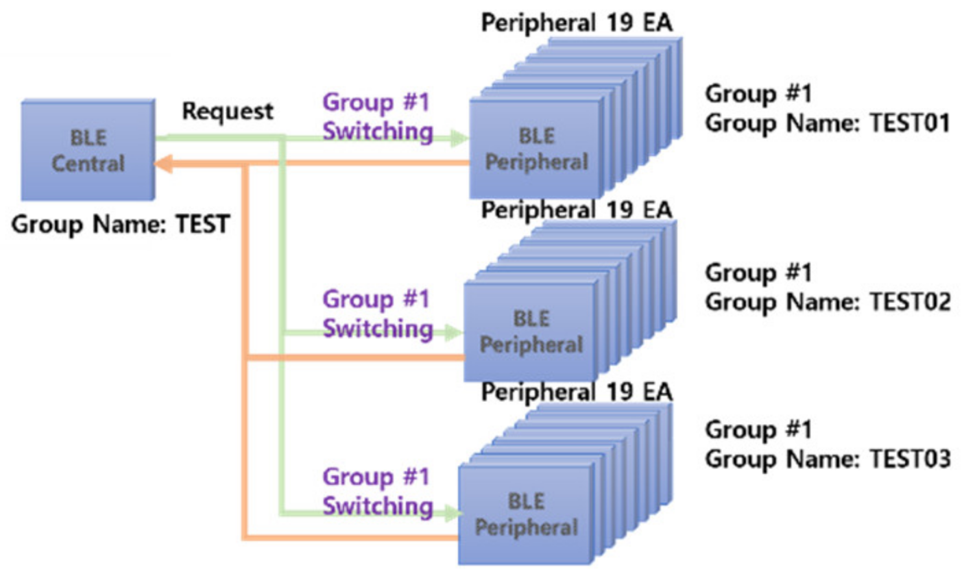
To implement BLE multilink communication by applying the group change method, the configuration included one central processor and three BLE peripheral groups (see Figure 10). Each group of BLE peripheral processors was composed of 19 IoT sensor nodes.
To connect the central processor with peripheral processors, the group to be connected to was set by changing the name of the target peripheral device. To set or change the group name of peripheral processors, it was defined in the device name parameter in the advertising packet.
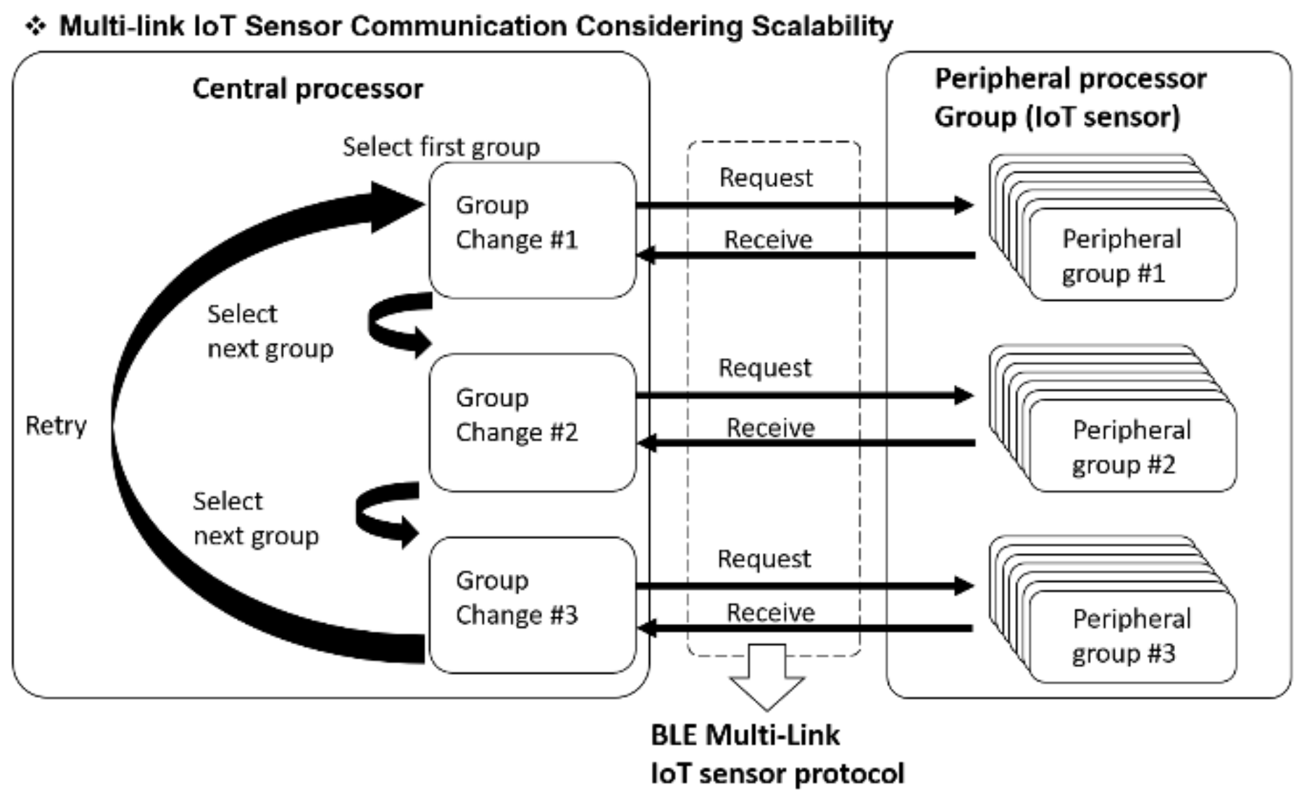
The central processor communicated with the peripheral processor via sequential connection to each group. The peripheral processors advertised the connection information and sent the sensor data when connected. The central processor received and processed sensor data.
To implement the BLE 5.2 multilink service, a module with which Nordic’s nRF52840 and nRF52832 chips were applied was used. BLE master gateway and BLE slave IoT sensor were manufactured via attachment to this module. The sensor data were transmitted and received via grouping in the BLE multilink method. To expand and implement connection nodes via grouping and group switching of IoT sensor nodes, UUID and NAME changes were made in the BLE central mode, and the group-switching method was implemented by developing BLE peripheral scan firmware. In the BLE peripheral mode, which is an IoT sensor node, it was developed in a way that parameters, such as group ID and group name, were changed with a mobile application, and data were transmitted and received via connection with the BLE central mode. Thus, a sensor group was designated, and the number of sensors that accessed the BLE multilink service was expanded through the group-switching method.
The central processor collected the data of peripheral processors by sequentially accessing groups 1–3 using group switching (see Figure 10) and performed group changes via repeated connections to groups 1–3 using the round robin method.
5.2. Test Scenario and Test Result by Function
5.2.1. Group Change in Central Processor
Figure 11 shows that the group name of central processor was set as TEST, and the group names of peripheral group were set as TEST01, TEST02, and TEST03.
After the device initialization was completed, the central processor set the group name from TEST01 and scanned the peripheral processors for 12 s. The scanned peripheral devices were sequentially accessed from Link No. 0 to Link No. 18.
The peripheral devices waited for connection after advertising the connection information simultaneously with power input. The central device for data collection set the group name to connect to after booting; it searched for advertising peripheral devices and sequentially connected to them.
The test scenario was as follows:
- To change the group for the multilink scalability test, the STM32F030 MCU of the central processor reset the BLE module for 500 ms and waited until the ACK signal was received.
- When the ACK signal was received, “test01,” the new group name for the multilink scalability test, was sent to the central BLE module.
- When the group name setting was completed, it waited for 12 s until the peripheral processors were connected to the BLE central processor, and the nRF52840 module connected with the peripheral processors that were advertising with the same group name.
- The test group name was automatically entered as the number obtained by adding 1 to the current group number (here, “test”). This process was the same as processes 1–3.
- The test group name was automatically entered as the number obtained by adding 1 to the current group number (here, “test03”). This process was the same as processes 1–3.
The test result is as follows:
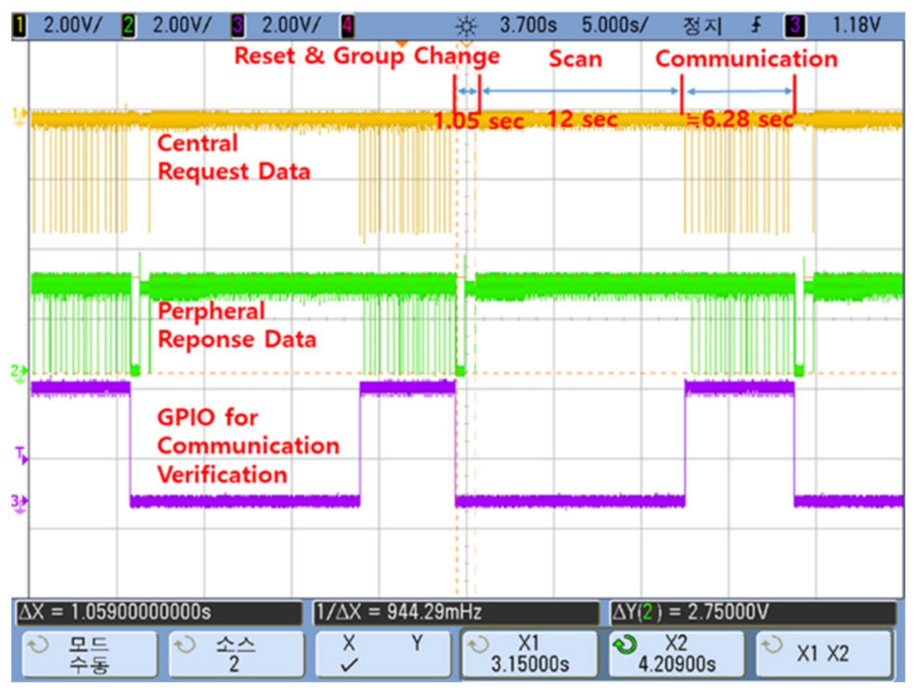
As shown in Figure 12, the STM32F030 MCU sent a group name setting command, and it was confirmed that the nRF52840 module changed the group name. Furthermore, an analysis of the group name change performance showed that it took 1.05 s in total after resetting the central BLE module until the ACK signal was sent out after the group name was changed.
5.2.2. Optimization of Scan Connection Interval between Processors
For the central processor to send or receive stable BLE data without any data loss, finding the optimal scan connection interval with peripheral processors was a critical point for stability and performance. To this end, the setting value of the basic scan interval connection had to be changed to the optimal value. Hence, an experiment was conducted to find the time required for optimizing it. The default value of this variable was 7.5 ms at the minimum and 40 ms at the maximum. For this purpose, one group was randomly selected, and the occurrence of data loss was checked while repeatedly sending and receiving the data of the 19 temperature sensors of peripheral processors. The time that was taken until data acquisition after changing three groups in total through this process was measured at approximately 60 s.
Experiments were conducted repeatedly to derive the optimal interval to send and receive stable BLE data packets from the central processor. This confirmed that the data were stably sent and received without data loss when the minimum value was 40 ms and the maximum value was 70 ms. Based on these results, the minimum value (NRE—BLE_SCAN_MN_CONNECTION_INTERVAL) was set at 40 ms, and the maximum value (NRF_BLE_SCAN_MAX_CONNECTION_INTERVAL) was set at 70 ms.
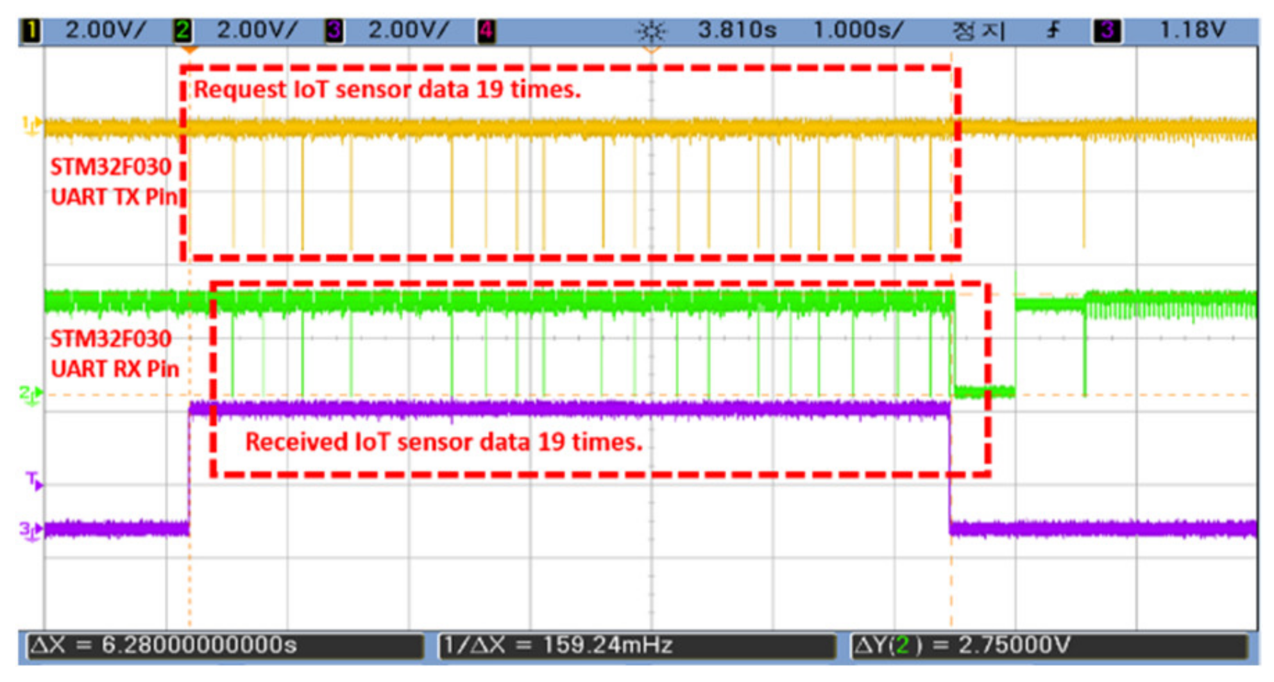
Figure 13 presents the result of an experiment conducted after reflecting the optimization time of the connection interval time in the parameters. We saw that normal communication was performed by sending data from 19 sensors and receiving data in 19 sensors in total. The dotted rectangles were the number of data sent from the central processor and received by the peripheral processor, and we saw that the two numbers were the same.
Typically, the risk of data loss increased if the data packet size was large, compared to the throughput for the scan interval time. To prevent this risk, this experiment used a fixed packet size of 20 bytes based on multilink communication.
5.2.3. Setting and Modification of Group Information through the App
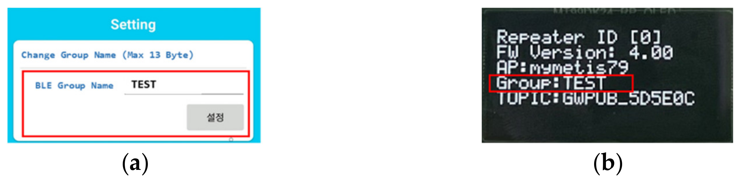
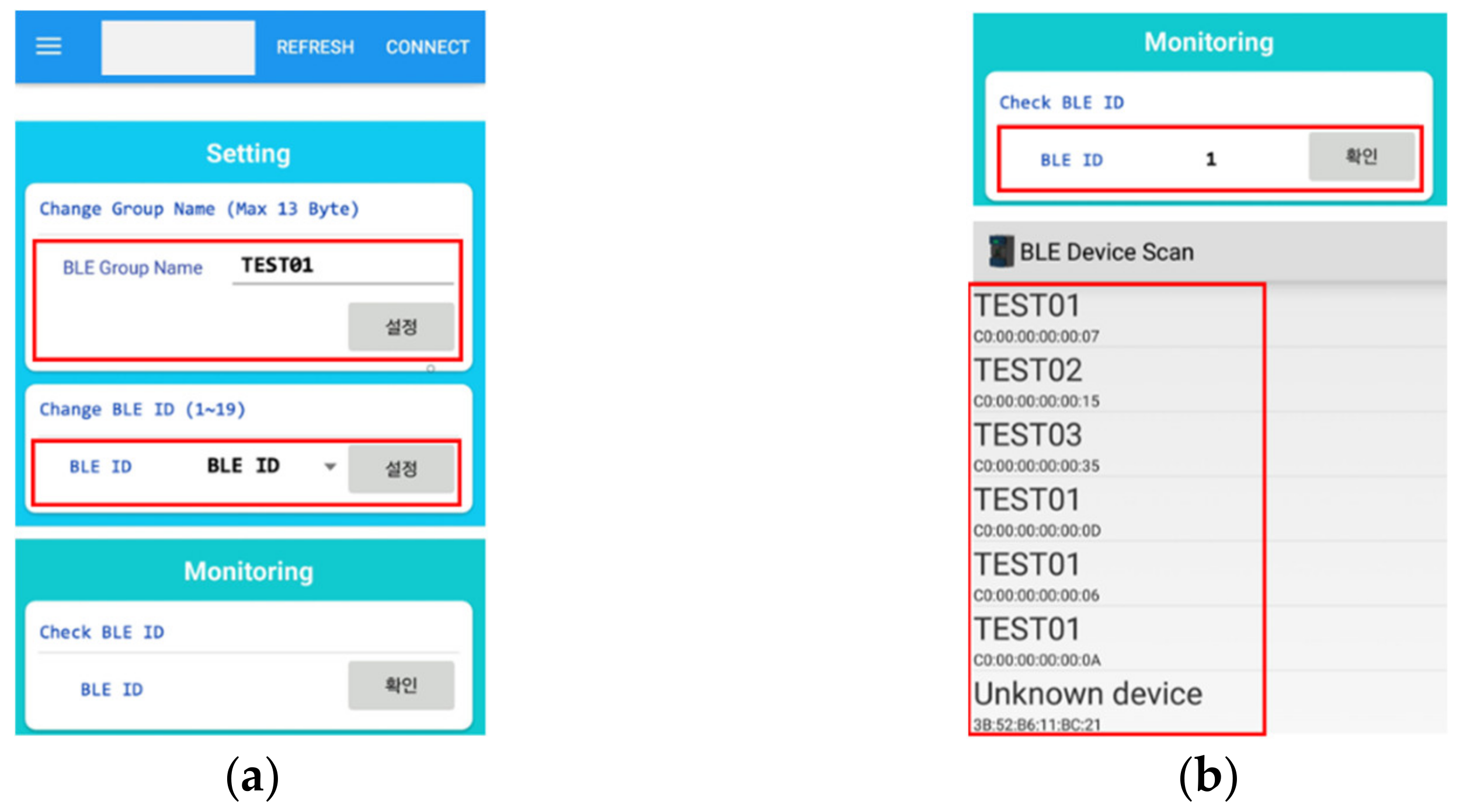
To use the BLE multilink communication, the group name and BLE ID had to be set through the mobile app. Only the group name was set for the central processor, whereas the BLE ID was additionally set for peripheral processors. The group name of the central processor was set through the mobile app, and the setting value was verified on the LCD display. The group name and BLE ID of peripheral processors were set and verified in the mobile app.
5.2.4. Verification of LCD Display Information
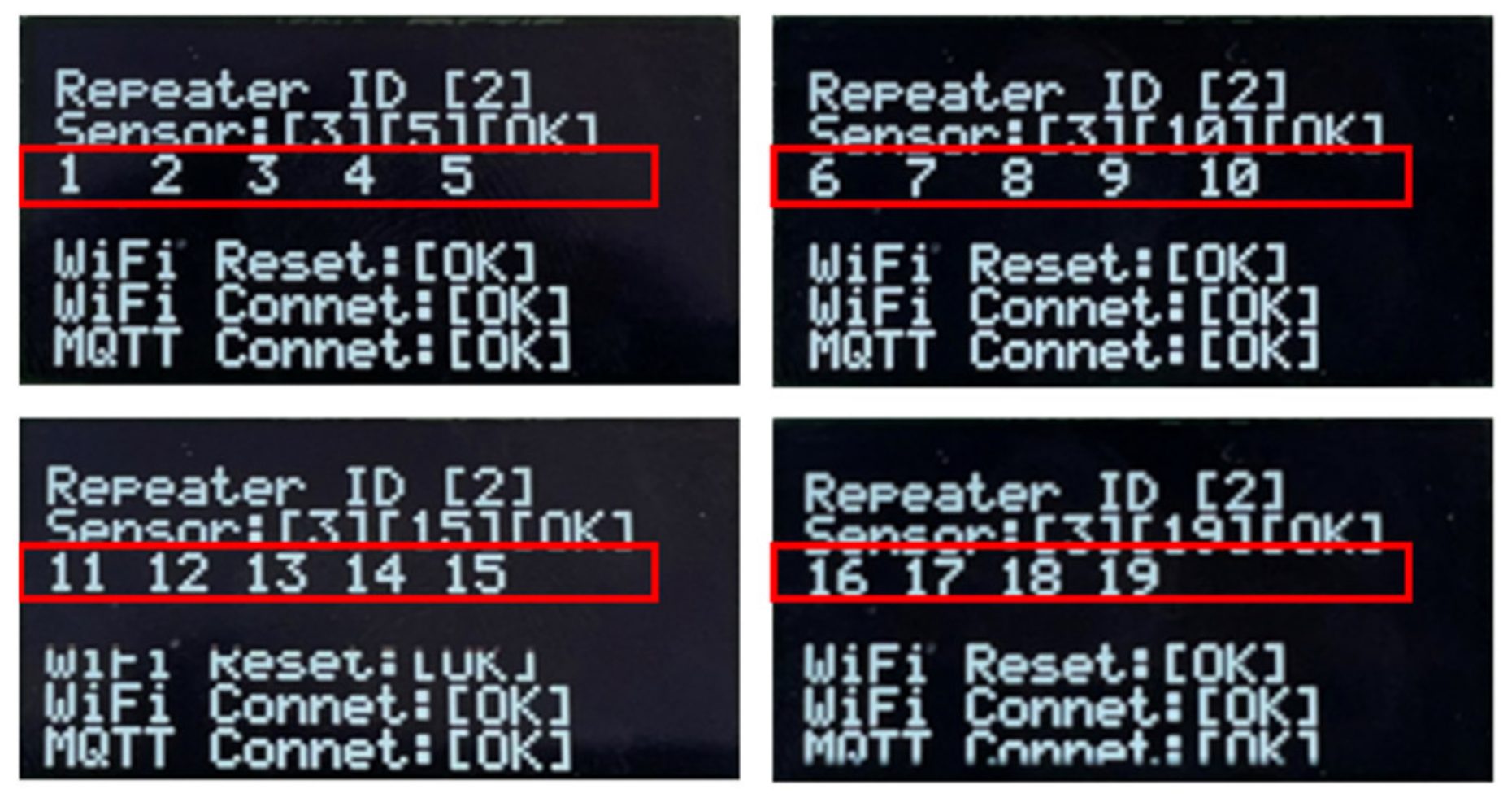
The BLE IDs of the peripheral processors set using the mobile app were sent and received sequentially from 1 to 19 sensors. For the central processor, it was checked whether the sent and received data were accurately displayed on the LCD screen. The data accuracy was confirmed through this process.
The numbers in the red rectangles in Figure 16 indicate that the BLE ID numbers were sent and received. Through this, the group name change resulted from the central processor, and the result of transmission and reception was verified.
5.3. Implications
The scalability of BLE multilink communication was implemented using multiple BLE peripheral-mode IoT sensors and group switching by fabricating a BLE central mode gateway and BLE peripheral-mode IoT sensors. This implications of the results of this study are as follows.
First, the limit of the number of IoT sensor nodes that were served using one central processor was maximized without additional equipment through the inter-group communication control algorithm of the BLE central mode and BLE peripheral mode. This experiment tested three groups in an environment where a total of 57 IoT nodes were served. However, this study verified the possibility of scaling up to more diverse and larger quantities of IoT nodes if the groups were changed using the round robin method by applying the BLE multilink communication technology to define more groups. This meant that it could be safely applied to the industry because it is scalable without additional central processors according to the increasing number of IoT sensor nodes, thus preventing data errors and equipment troubles between central processors. Second, the data loss of the communication between the BLE multilink central and peripheral processors was prevented by optimizing the scan connection interval parameter based on the data of 57 IoT nodes. This meant that, when more diverse and larger quantities of IoT nodes were connected and used, optimization for the IoT sensor transmission and reception had to be performed through periodic performance monitoring. Third, the time required for resetting the central BLE module, changing the group name, and acquiring the data of peripheral processors was measured, and it took 19.33 s in total. This meant that it required 1.017 s at minimum per IoT node, considering that there were 19 peripheral processors. Therefore, a method of minimizing the delay of scalable multilink BLE wireless communication had to be considered to apply it to industrial sites. This problem can be solved by implementing a group change method with no latency by using three BLE Central Modules in the Central processor. This is because of the decrease in the delay time by configuring a method of one group communicating data, while the other two groups change groups in advance so that the Central MCU can communicate immediately with the changed group. Fourth, the mobile application considerably improved the convenience of work and the efficiency of operation because the BLE group name and ID number setting of the BLE peripheral mode were easily changed without a separate device. The applicability of the BLE wireless network communication for IoT monitoring products was also verified. Lastly, when the scalable technology was applied through the BLE wireless network communication, it sufficiently replaced the conventional wired equipment. This had various advantages such as lower equipment manufacturing cost, shorter schedule, and easier maintenance, and also helped in the management of communication pipes and stability.
However, the current developed method has the following limitations.
First, the central processor fixed the reset time to 0.5 s for stable rebooting of the central BLE module for group switching, and this caused a delay in BLE communication. To solve this problem, the software booting algorithm needs to be improved. Second, an improvement measure for variable length transmission and reception data was required to optimize the scan connection interval parameter more flexibly for communication between processors. Third, the BLE wireless communication might depend on the performance of the BLE multiple accesses according to the RF antenna performance.
Fourth, in order to reduce the BLE scan time, the BLE Central Module must eliminate the reconnection time via cross-communication.
6. Conclusions
Conventional multilink IoT sensor network communication based on BLE enables only processing of up to 19 peripheral nodes per central device. In this study, a scalable multi-link IoT sensor network communication implementation was developed through a new group-switching algorithm based on BLE 5 and industrial applicability was verified.
This design offers the benefits of minimizing the addition of a central processor and increasing the number of IoT sensor nodes. In addition, this device environment lowered the possibility of data errors and equipment troubles due to communication interference between central processors. In the end, this is a critical advantage when applying it to the industry. The scalability and various advantages of this algorithm will be expected to help accelerate various services including IoT monitoring products via the application of BLE 5 wireless communication by innovatively improving the constraint of accessing up to 19 nodes per central device in the conventional multilink IoT sensor communication.
Future work should investigate measures to minimize the communication delay according to the variable data size for transmission and receipt of BLE communication and to maximize reliability by increasing the communication range through the measurement and improvement of antenna performance.
Author Contributions
Conceptualization, Y.-M.Y. and S.-H.K.; methodology, Y.-M.Y.; software, D.-S.R.; validation, D.-S.R., Y.-M.Y. and S.-H.K.; formal analysis, D.-S.R., Y.-M.Y. and S.-H.K.; investigation, D.-S.R., Y.-M.Y. and S.-H.K.; resources, D.-S.R., Y.-M.Y. and S.-H.K.; data curation, D.-S.R., Y.-M.Y. and S.-H.K.; writing—original draft preparation, D.-S.R., Y.-M.Y. and S.-H.K.; writing—review and editing, S.-H.K.; visualization, D.-S.R., S.-H.K.; supervision, S.-H.K.; project administration, S.-H.K.; funding acquisition, S.-H.K. All authors have read and agreed to the published version of the manuscript.
Funding
This research received no external funding.
Conflicts of Interest
The authors declare no conflict of interest.
References
- Jung, J.M.; Lee, Y.S.; Kim, Y.H.; Kim, K.M. Development of industrial wireless network module system for reliability monitoring of electrical equipment. In Proceedings of the Korean Institute of Electrical Engineers Conference, Busan, Korea, 15–17 July 2020; pp. 2159–2160. [Google Scholar]
- Je, J.K.; Chun, T.Y.; Shin, Y.H. Performance improvement strategy for fieldbus in industrial wired and wireless network. In Proceedings of the Korean Institute of Electrical Engineers Conference, Pyeongchang, Korea, 27–28 October 2006; pp. 473–475. [Google Scholar]
- Sung, K.; Soh, W.J. A study on the performance verification of Bluetooth5 technology. In Proceedings of the JKIIT Conference, Daejeon, Korea, 1–2 December 2017; pp. 215–271. [Google Scholar]
- Ryu, D.H. Development of BLE sensor module based on open source for IoT applications. J-KICS 2015, 10, 419–424. [Google Scholar] [CrossRef] [Green Version]
- Porte, J.; Briones, A.; Maso, J.M.; Pares, C.; Zaballos, A.; Pijoan, J.L. Heterogeneous wireless IoT architecture for natural disaster monitorization. EURASIP J. Wirel. Commun. Netw. 2020, 1, 127. [Google Scholar] [CrossRef]
- Available online: https://infocenter.nordicsemi.com/index.jsp?topic=%2Fsds_s140%2FSDS%2Fs1xx%2Fs140.html (accessed on 11 May 2021).
- Cox, B.; Van der Perre, L.; Wielandt, S.; Ottoy, G.; De Strycker, L. High precision hybrid RF and ultrasonic chirp-based ranging for low-power IoT nodes. EURASIP J. Wirel. Commun. Netw. 2020, 1, 1–24. [Google Scholar] [CrossRef]
- Li, J.W.; Chang, Y.C.; Xu, M.X.; Huang, D.Y. A health management service with beacon-based identification for preventive elderly care. J. Inf. Process. Syst. 2020, 16, 648–662. [Google Scholar]
- Frost & Sullivan, Markets and Markets, TechNavio, “IoT Sensor Market”, Global Market Trends Report. 2021. Available online: http://www.innopolis.or.kr (accessed on 29 August 2021).
- Rutronik Electronica Worldwide, White Paper Bluetooth5 “Determination of Practical Extremes of Bluetooth Low Energy: Throughput, Energy Consumption and Maximum Range. Available online: https://www.bluetooth.com/about-us/contact-us/ (accessed on 20 September 2021).
- Kwak, J.; Sung, Y. Beacon-based indoor location measurement method to enhanced common chord-based trilateration. J. Inf. Process. Syst. 2017, 13, 1640–1651. [Google Scholar]
- Ghafi, H.K.; Spindelberger, C.; Arthaber, H. Modeling of co-channel interference in bluetooth low energy based on measurement data. EURASIP J. Wirel. Commun. Netw. 2021, 1, 117. [Google Scholar]
- Gomez, C.; Oller, J.; Paradells, J. Overview and evaluation of bluetooth low energy: An emerging low-power wireless technology. Sensors 2012, 12, 11734–11753. [Google Scholar] [CrossRef]
- Yang, Y.; Guo, M.; Tang, F.; Zhang, G. Black Bridge: A Scatternet Formation Algorithm for Solving a New Emerging Problem. In Proceedings of the IEEE 2009 International Conference on Computational Science and Engineering, Vancouver, BC, Canada, 29–31 August 2009; pp. 470–475. [Google Scholar]
- Darroudi, S.M.; Gomez, C. Bluetooth low energy mesh networks: A survey. Sensors 2017, 17, 1467. [Google Scholar] [CrossRef] [PubMed] [Green Version]
- Jang, R.Y.; Lee, J.U.; Jung, S.J.; Soh, W.Y. Data transmission method using broadcasting in Bluetooth low energy environment. J. Digit. Contents Soc. 2018, 19, 963–969. [Google Scholar] [CrossRef]
- Bluetooth SIG. Bluetooth® 5.3—What’s New for IoT Device Makers and Application Developers? Available online: https://community.silabs.com/s/share/a5U1M000000koJ8UAI/bluetooth-53-whats-new-for-iot-device-makers-and-application-developers?language=en_US (accessed on 10 August 2021).
- Martine, W. Bluetooth® Core Specification Version 5.3 Feature Enhancements; BlueTooth®: Kirkland, WA, USA, 2021; Volume 6, pp. 7–39. [Google Scholar]
- Basu, S.S.; Haxhibeqiri, J.; Baert, M.; Moons, B.; Karaagac, A.; Crombez, P.; Camerlynck, P.; Hoebeke, J. An end-to-end LwM2M-based communication architecture for multimodal NB-IoT/BLE devices. Sensors 2020, 20, 2239. [Google Scholar] [CrossRef] [PubMed] [Green Version]
- Garcia-Espinosa, E.; Longoria-Gandara, O.; Pegueros-Lepe, I.; Veloz-Guerrero, A. Power Consumption Analysis of Bluetooth Low Energy Commercial Products and Their Implications for IoT Applications. Electronics 2018, 7, 386. [Google Scholar] [CrossRef] [Green Version]
- Badihi, B.; Sheikh, M.U.; Ruttik, K.; Jantti, R. On Performance Evaluation of BLE 5 in Indoor Environment: An Experimental Study. In Proceedings of the 2020 IEEE 31st Annual International Symposium on Personal, Indoor and Mobile Radio Communications, London, UK, 31 August–3 September 2020; pp. 1–5. [Google Scholar]
- Nouali, O.; Moussaoui, S.; Derder, A. A BLE-based Data Collection System for IoT. In Proceedings of the IEEE 2015 First International Conference on New Technologies of Information and Communication (NTIC), Mila, Algeria, 8–9 November 2015; pp. 1–5. [Google Scholar]
- Vance, E.; Nahapetian, A. Bluetooth-based context modeling. In Proceedings of the 4th ACM MobiHoc Workshop on Experiences with the Design and Implementation of Smart Objects, Los Angeles, CA, USA, 25 June 2018; pp. 1–6. [Google Scholar] [CrossRef]
- Lee, S.Y.; Kim, M.E.; Son, J.K.; Jeon, J.H.; Lee, K.B. Implementation of BLE multi-link for group communication between unmanned vehicles. J-KICS 2020, 45, 311–320. [Google Scholar] [CrossRef]
- Fourati, L.C.; Said, S. Remote Health Monitoring Systems Based on Bluetooth Low Energy (BLE) Communication Systems. In Proceedings of the ICOST 2020, Hammamet, Tunisia, 24–26 June 2020; pp. 41–54. [Google Scholar]
- Ayele, E.D.; Das, K.; Meratnia, N.; Havinga, P.J. Leveraging BLE and LoRa in IoT Network for Wildlife Monitoring System (WMS). In Proceedings of the 2018 IEEE 4th World Forum on Internet of Things (WF-IoT), Marina Bay Sands Hotel, Singapore, 5–8 February 2018; pp. 342–348. [Google Scholar]
- Zuo, C.; Wen, H.; Lin, Z.; Zhang, Y. Automatic Fingerprinting of Vulnerable IoT Devices with Static UUIDs from Mobile Apps. In Proceedings of the 2019 ACM SIGSAC Conference on Computer and Communications Security, London, UK, 11–15 November 2019; Volume 11, pp. 1469–1483. [Google Scholar]
- Antonioli, D.; Tippenhauer, N.O.; Rasmussen, K. Key negotiation downgrade attacks on bluetooth and bluetooth low energy. ACM Trans. Priv. Secur. 2020, 23, 1–28. [Google Scholar] [CrossRef]
- Jeong, P.S.; Cho, Y.H. Smart factory safety management system using Bluetooth. Korea Converg. Soc. 2019, 10, 47–53. [Google Scholar]
- Park, S. D-PARK: User-Centric Smart Parking System over BLE-Beacon Based Internet of Things. Electronics 2021, 10, 541. [Google Scholar] [CrossRef]
- Giuliano, R.; Cardarilli, G.C.; Cesarini, C.; Di Nunzio, L.; Fallucchi, F.; Fazzolari, R.; Mazzenga, F.; Re, M.; Vizzarri, A. Indoor localization system based on bluetooth low energy for museum applications. Electronics 2020, 9, 1055. [Google Scholar] [CrossRef]
- Demrozi, F.; Turetta, C.; Chiarani, F.; Kindt, P.H.; Pravadelli, G. Estimating indoor occupancy through low-cost BLE devices. IEEE Sens. J. 2021, 21, 17053–17063. [Google Scholar] [CrossRef]
- Available online: https://www.nordicsemi.com/Products/Development-software/nRF5-SDK/Download#infotabs (accessed on 11 May 2021).
- Core Specification Working Group. Bluetooth Core Specification, v5.3; BlueTooth SIG: Kirkland, WA, USA, 2021; Volume 7, pp. 1819–1845. [Google Scholar]
Figure 1.
BLE protocol stack [14].
Figure 1.
BLE protocol stack [14].

Figure 2.
Research process.

Figure 3.
Conceptual diagram of multilink IoT sensor communication.

Figure 4.
Central processor block diagram.

Figure 5.
Sequence diagram of central processor.

Figure 6.
Source code of rename group.

Figure 7.
Peripheral processor block diagram.

Figure 8.
Sequence diagram of peripheral processor.

Figure 9.
PCBs of central and peripheral processors: (a) central processor image; (b) peripheral processor image.
Figure 9.
PCBs of central and peripheral processors: (a) central processor image; (b) peripheral processor image.

Figure 10.
Concept of IoT sensor experiment using BLE multilink communication.

Figure 11.
Experimental setup.

Figure 12.
Result of group change for central processor.

Figure 13.
Data sent and received after the scan connection interval optimization.

Figure 14.
Setting and modification of central processor group information through the app: (a) setting and modification; (b) verification of group name and BLE ID.
Figure 14.
Setting and modification of central processor group information through the app: (a) setting and modification; (b) verification of group name and BLE ID.

Figure 15.
Setting and modification of peripheral processor group information through the app: (a) setting and modification; (b) verification of group name and BLE ID.
Figure 15.
Setting and modification of peripheral processor group information through the app: (a) setting and modification; (b) verification of group name and BLE ID.

Figure 16.
LCD display information.


Table 1.
The main advantages and disadvantages of related papers.
| Category | Ref. | Pros | Cons |
|---|---|---|---|
| Improvement of BLE communication architecture | [4] | Multiple BLE sensors applied a number of 7 | No evaluation for sensor scalability |
| [27] | Proposal of architecture prepared for the combination of various IoT technologies | No reflection for various architectural constraints | |
| [26] | Design for dual wireless IoT network and ultra-low-power IoT device | Shortage of battery configuration and real-time performance, and insufficient reliability of sensor nodes | |
| [25] | Wearable sensor communication | BLE 1:1 communication only | |
| [28] | Development environment reflecting the lowest power consumption measurement | Limitations of various applications in different development environments | |
| Reinforcement of data collection performance | [19] | Dissimilar communication | No evaluation for sensor scalability |
| [21] | Performance evaluation through data analysis | Scalability performance limitations when BLE data increases | |
| [29] | Sensor with human physiological characteristics applied | Limitation for application of the embedded system | |
| [33] | Broadcasting with data division method considering the reception rate | No consideration for stability and security when BLE data increases | |
| [23] | Efficient data collection in a mobile environment | BLE 1:1 communication only | |
| Security | [27] | Detailed evaluation of security vulnerabilities in the mobile app environment | BLE 1:1 communication only |
| [34] | Strengthening security vulnerabilities of BLE devices | Insufficient response to new machinery |
Table 2.
Central processor request protocol.
| No | Parameter | Test Value | Size |
|---|---|---|---|
| 1 | Start Code 1 | M | 1 Byte |
| 2 | Start Code 2 | E | 1 Byte |
| 3 | Length | 10 | 1 Byte |
| 4 | Command | 0 multiplied by 00 | 1 Byte |
| 5 | Reserved 1 | - | 1 Byte |
| 6 | BLE ID | 1~19 | 1 Byte |
| 7 | Reserved 2 | - | 1 Byte |
| 8 | Check sum | SUM | 1 Byte |
| 9 | End Code 1 | 0 multiplied by 0D | 1 Byte |
| 10 | End Code 2 | 0 multiplied by 0A | 1 Byte |
Table 3.
Peripheral processor response protocol.
| No | Parameter | Value | Size |
|---|---|---|---|
| 1 | Start Code 1 | M | 1 Byte |
| 2 | Start Code 2 | E | 1 Byte |
| 3 | Length | 20 | 1 Byte |
| 4 | Command | 0 multiplied by 01 | 1 Byte |
| 5 | Request ID | 1~19 | 1 Byte |
| 6 | Reserved | 0 | 1 Byte |
| 7 | Reserved | 0 | 1 Byte |
| 8 | Temp 1 | 0~99 | 2 Bytes |
| 9 | Temp 2 | 0~99 | 2 Bytes |
| 10 | Temp 3 | 0~99 | 2 Bytes |
| 11 | Reserved 1 | 0 | 2 Bytes |
| 12 | Reserved 2 | 0 | 1 Byte |
| 13 | Reserved 3 | 0 | 1 Byte |
| 14 | Reserved 4 | 0 | 1 Byte |
| 15 | Reserved 5 | 0 | 1 Byte |
| 16 | Check sum | SUM | 1 Byte |
Table 4.
Group name setting protocol.
| No | Parameter | Value | Size |
|---|---|---|---|
| 1 | Start Code 1 | M | 1 Byte |
| 2 | Start Code 2 | E | 1 Byte |
| 3 | Length | 6~18 | 1 Byte |
| 4 | Command | F0 | 1 Byte |
| 5 | Group name | name | 13 Bytes |
| 6 | Check sum | SUM | 1 Byte |
Table 5.
BLE ID setting protocol.
| No | Parameter | Value | Size |
|---|---|---|---|
| 1 | Start Code 1 | M | 1 Byte |
| 2 | Start Code 2 | E | 1 Byte |
| 3 | Length | 6 | 1 Byte |
| 4 | Command | F1 | 1 Byte |
| 5 | BLE ID | 1~19 | 1 Byte |
| 6 | Check sum | SUM | 1 Byte |
Publisher’s Note: MDPI stays neutral with regard to jurisdictional claims in published maps and institutional affiliations. |
© 2021 by the authors. Licensee MDPI, Basel, Switzerland. This article is an open access article distributed under the terms and conditions of the Creative Commons Attribution (CC BY) license (https://creativecommons.org/licenses/by/4.0/).
Share and Cite
MDPI and ACS Style
Ryu, D.-S.; Yeon, Y.-M.; Kim, S.-H. Multilink Internet-of-Things Sensor Communication Based on Bluetooth Low Energy Considering Scalability. Electronics 2021, 10, 2335. https://0-doi-org.brum.beds.ac.uk/10.3390/electronics10192335
AMA Style
Ryu D-S, Yeon Y-M, Kim S-H. Multilink Internet-of-Things Sensor Communication Based on Bluetooth Low Energy Considering Scalability. Electronics. 2021; 10(19):2335. https://0-doi-org.brum.beds.ac.uk/10.3390/electronics10192335
Chicago/Turabian StyleRyu, Dong-Suk, Yeung-Mo Yeon, and Seung-Hee Kim. 2021. "Multilink Internet-of-Things Sensor Communication Based on Bluetooth Low Energy Considering Scalability" Electronics 10, no. 19: 2335. https://0-doi-org.brum.beds.ac.uk/10.3390/electronics10192335
Note that from the first issue of 2016, this journal uses article numbers instead of page numbers. See further details here.