
Compensation of Unbalanced Low-Voltage Grids Using a Photovoltaic Generation System with a Dual Four-Leg, Two-Level Inverter

 , , , , and
Abstract
:1. Introduction
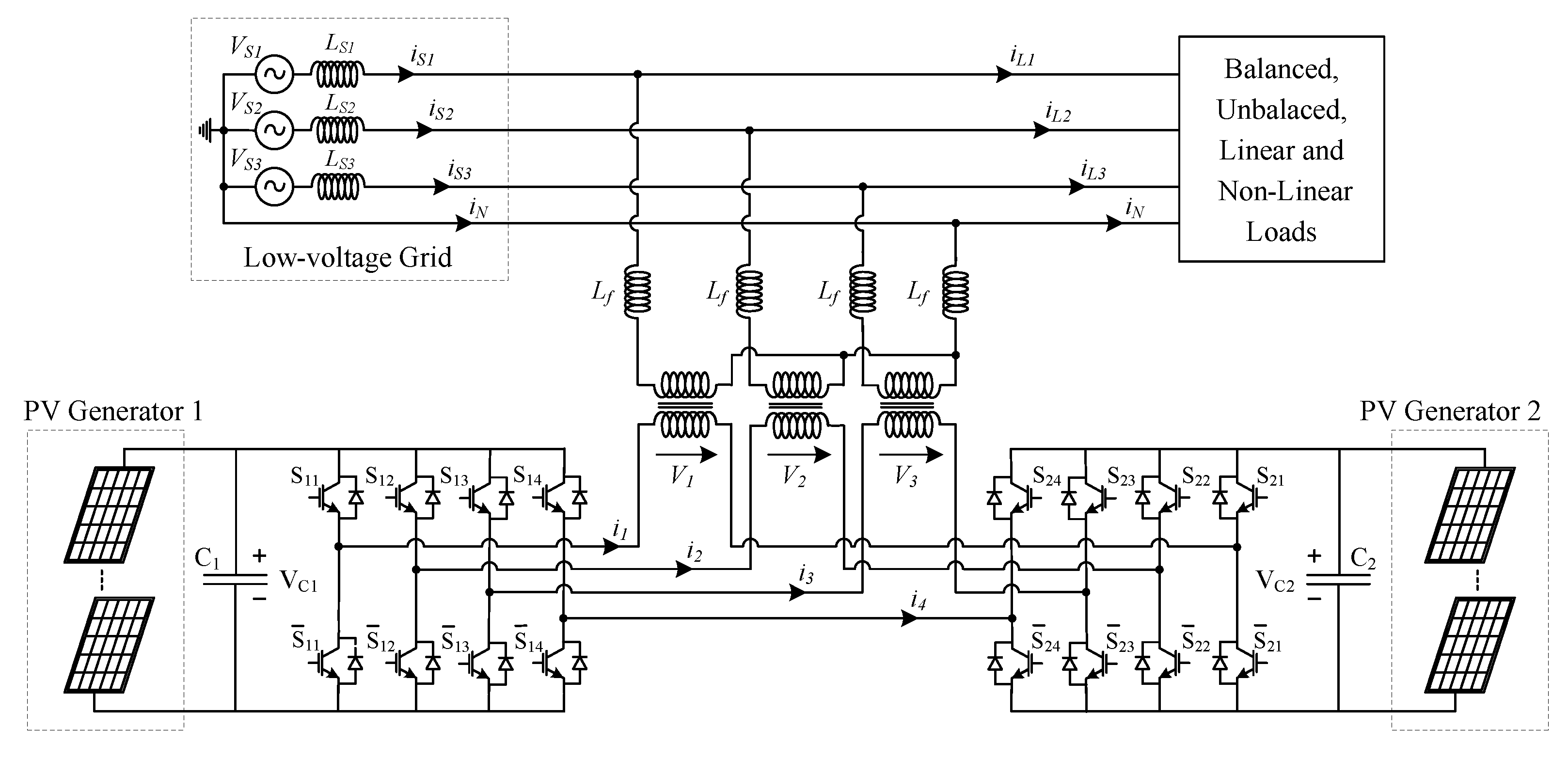
2. Proposed System
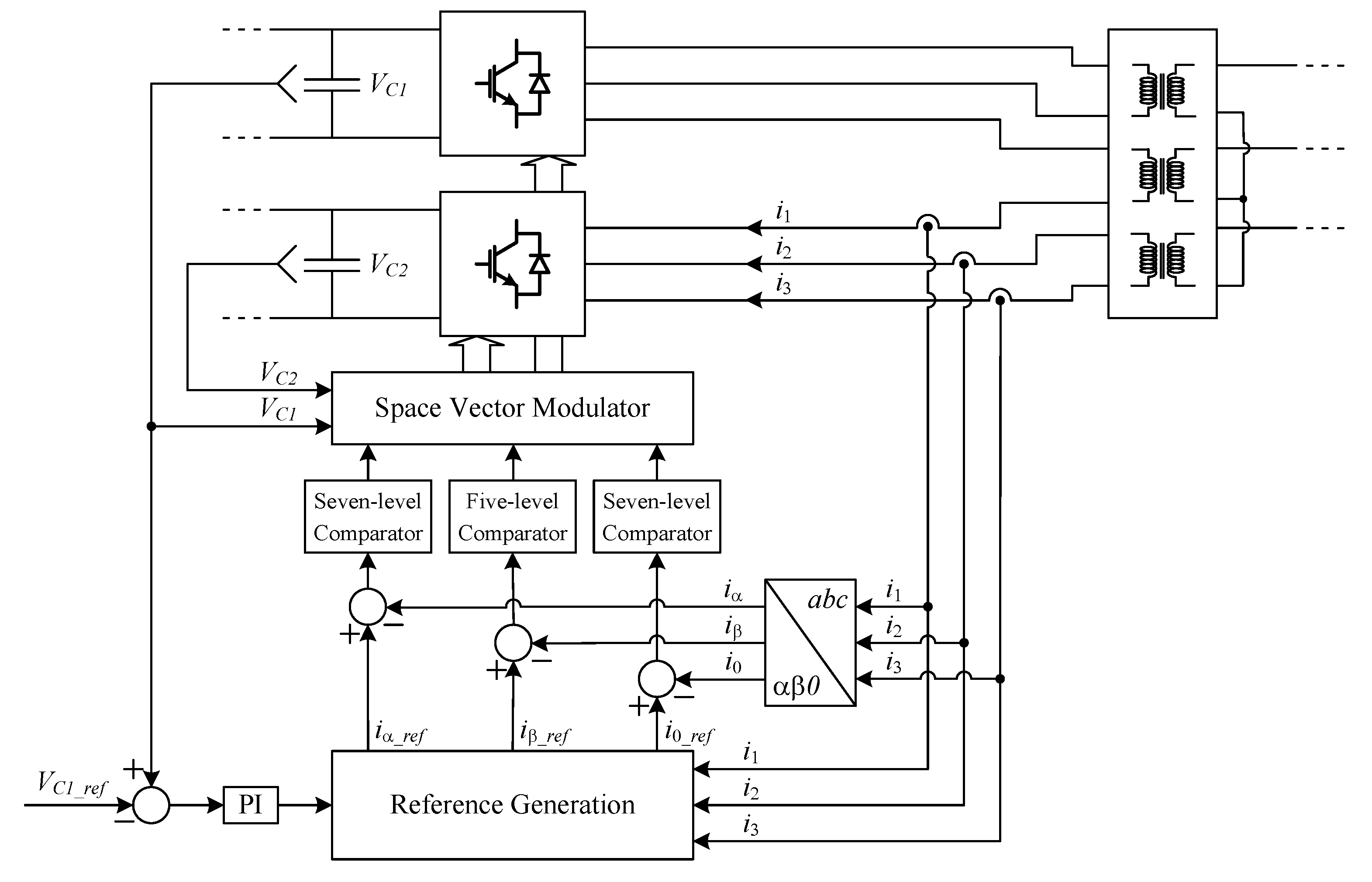
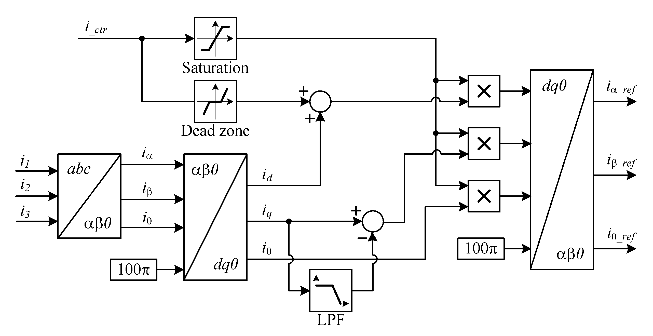
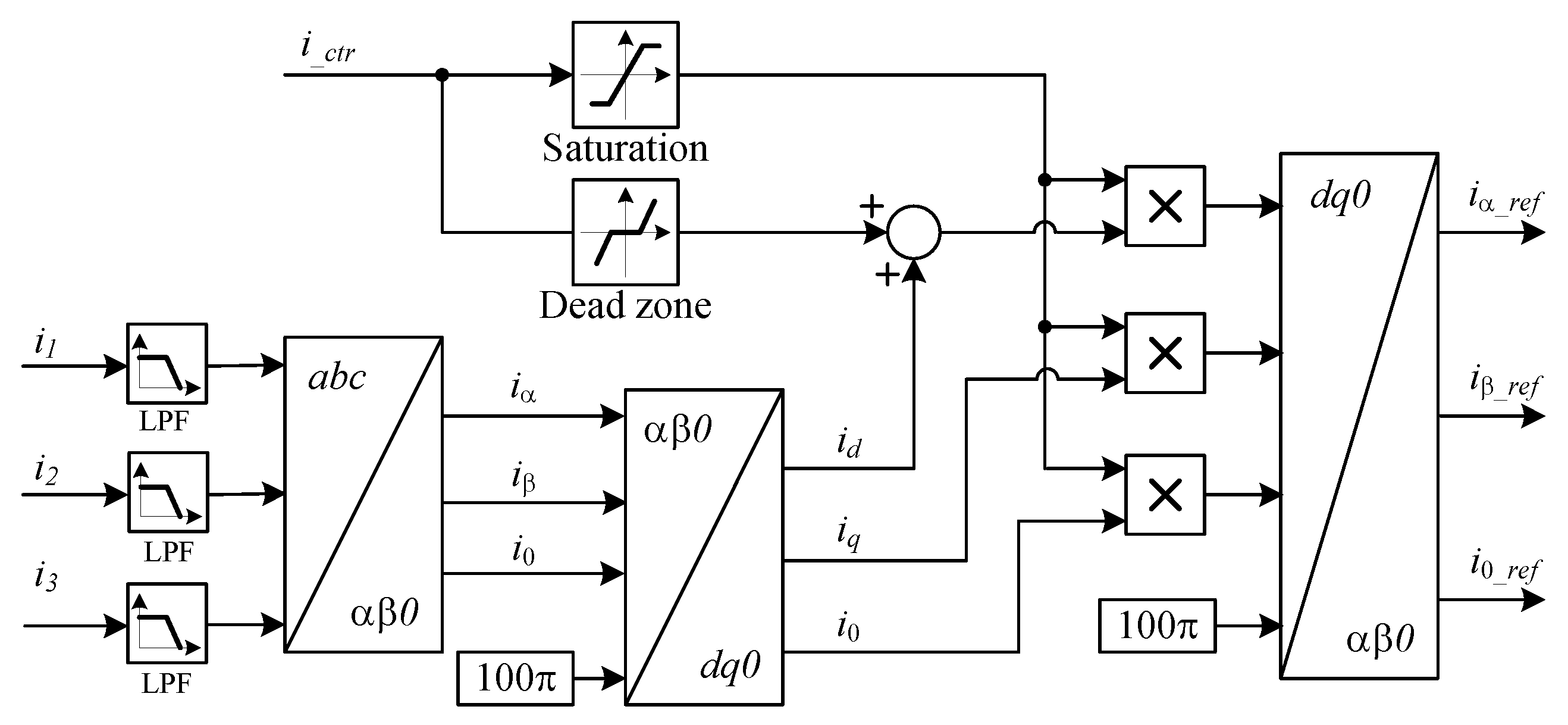
3. Control Strategy
- The generated PV power is lower than the unbalanced grid load power;
- The generated PV power is higher than the unbalanced grid load power.
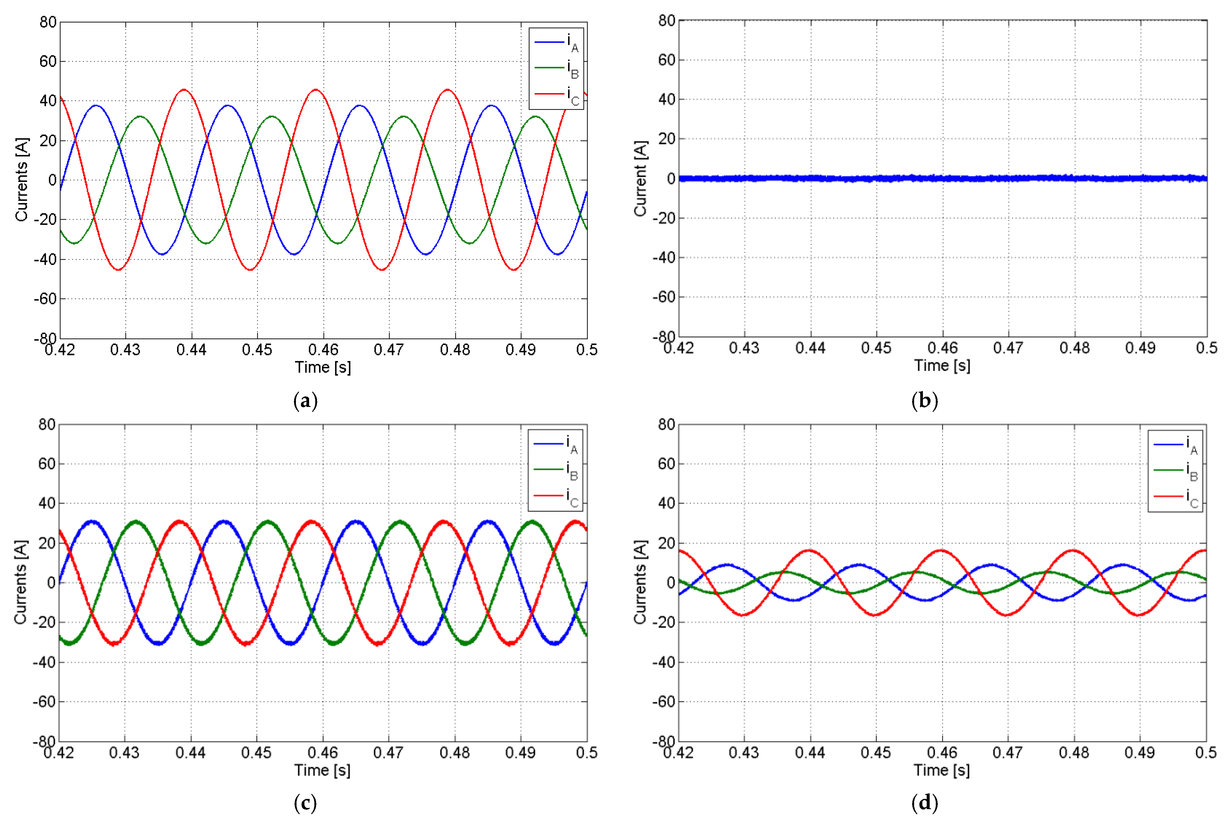
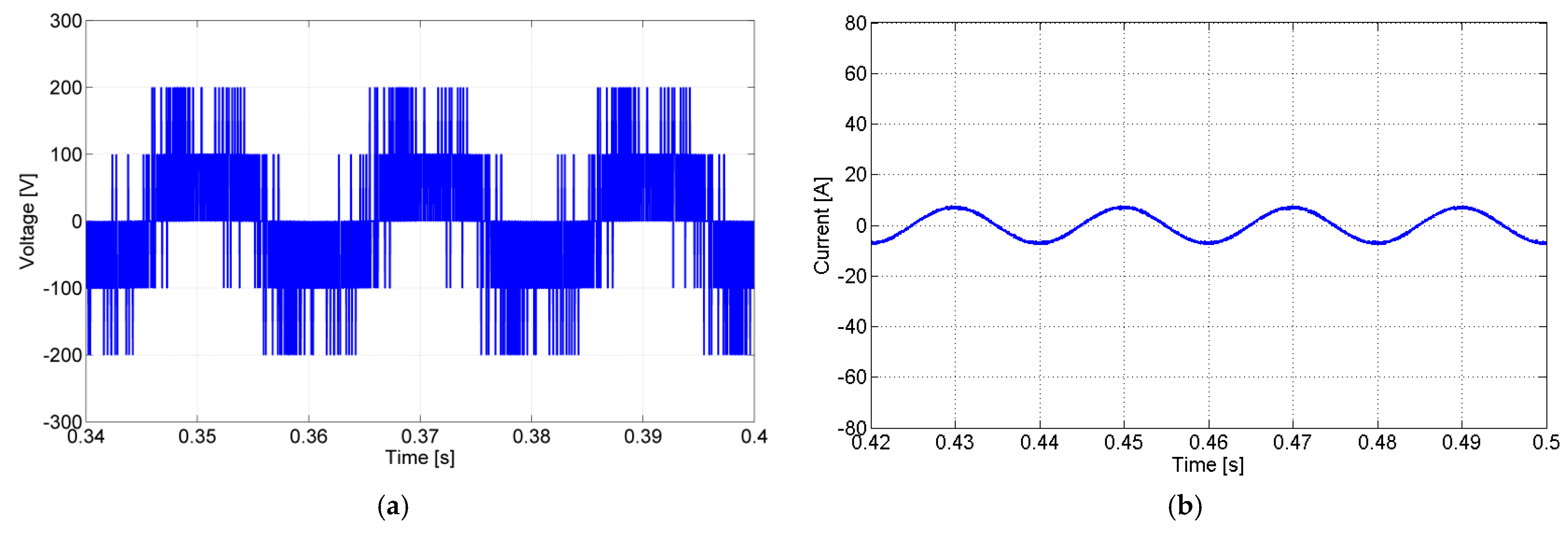
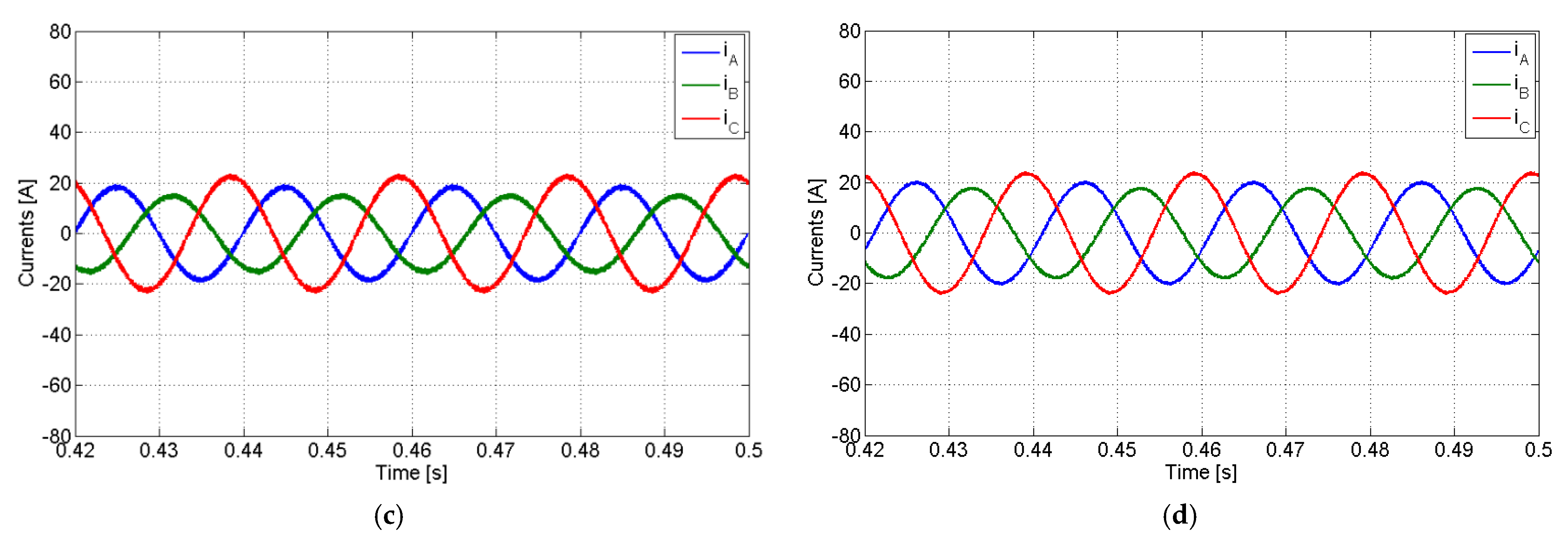
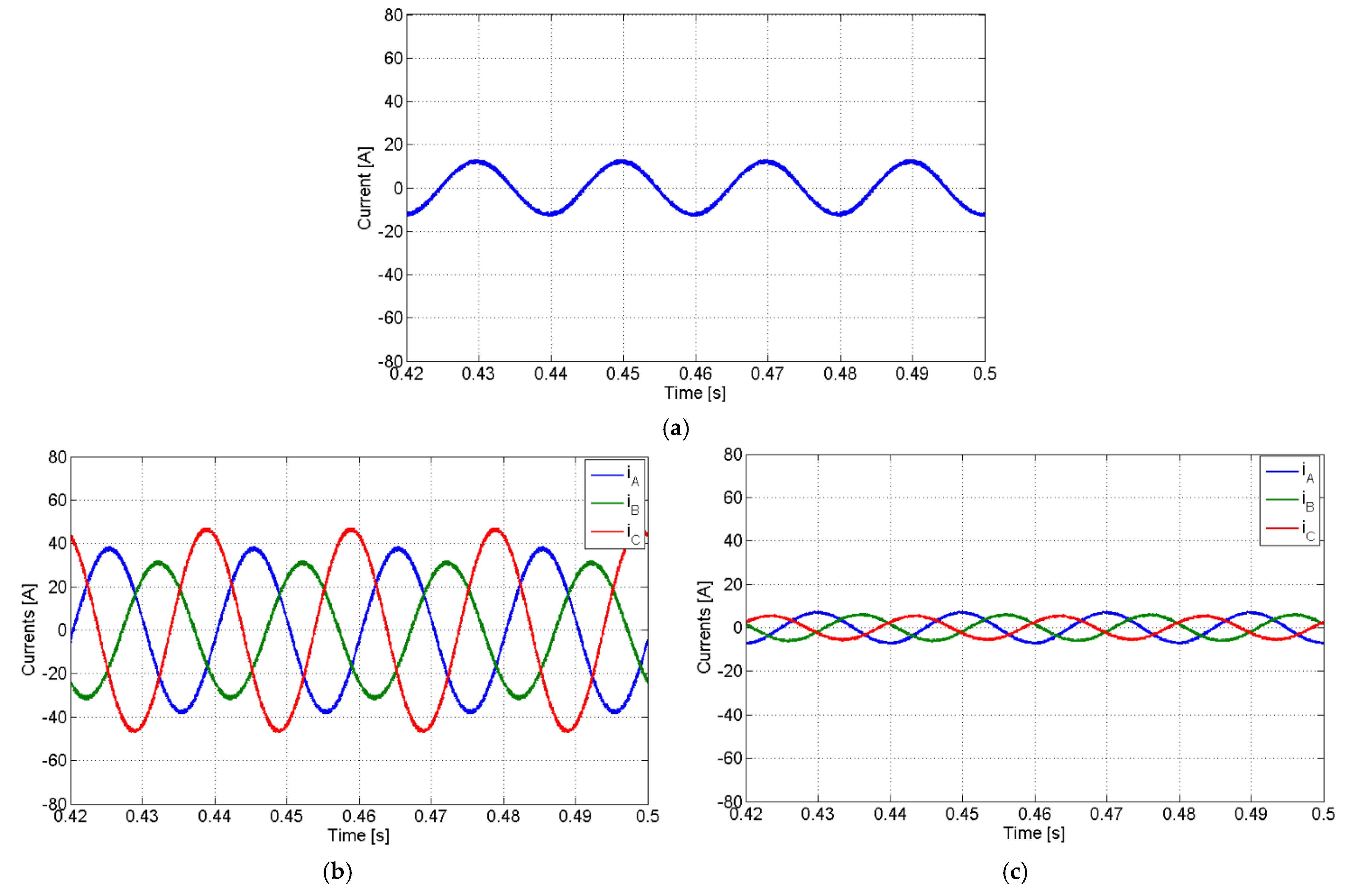
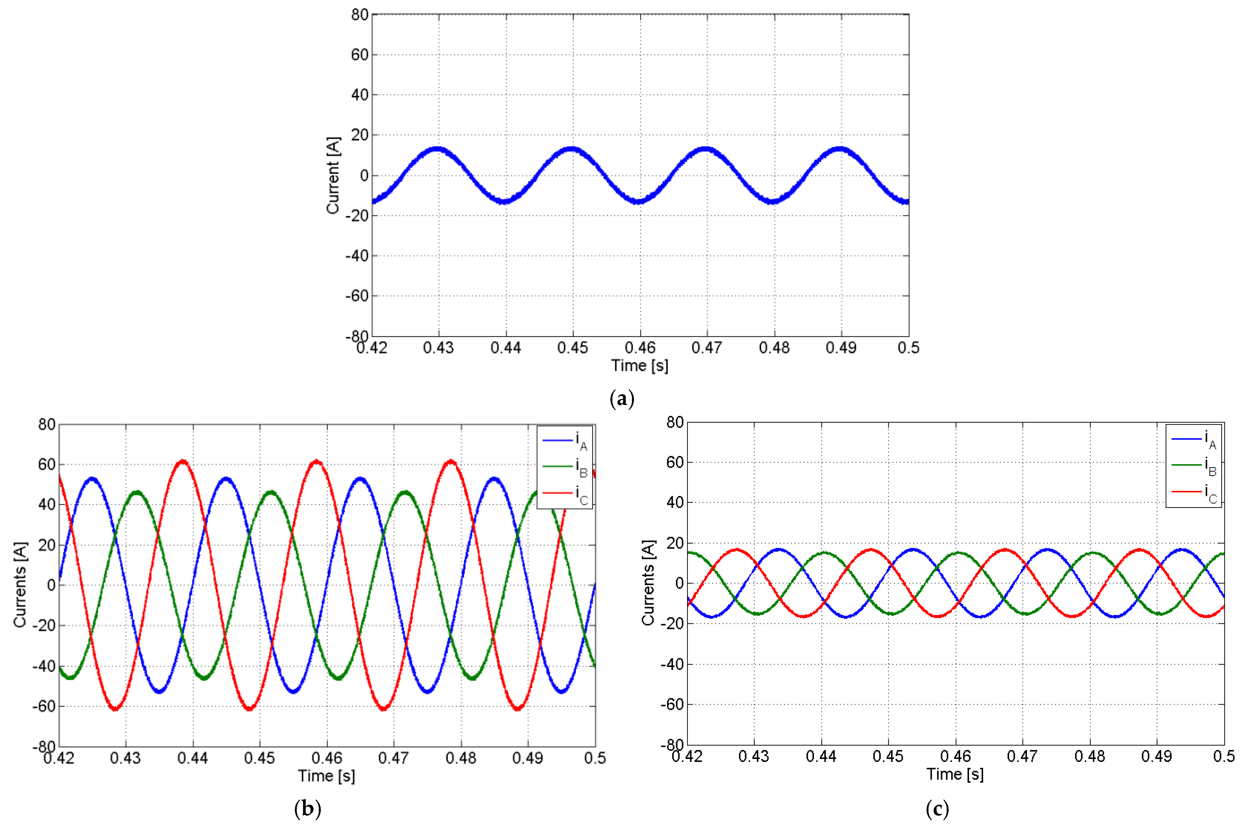
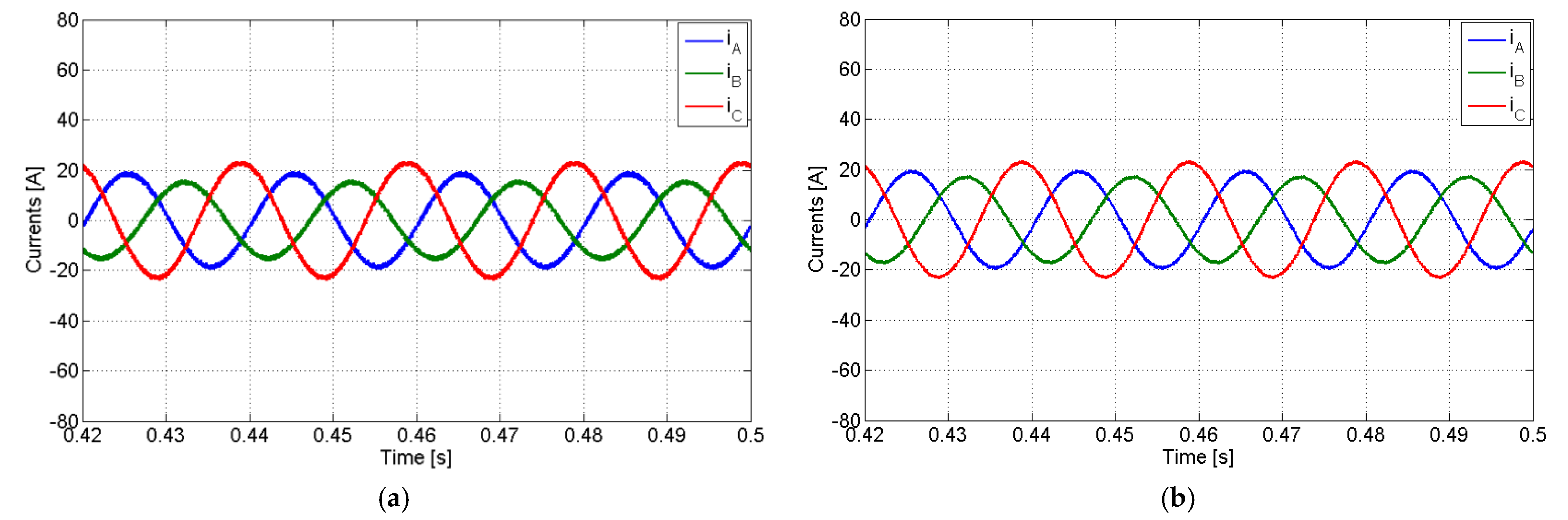
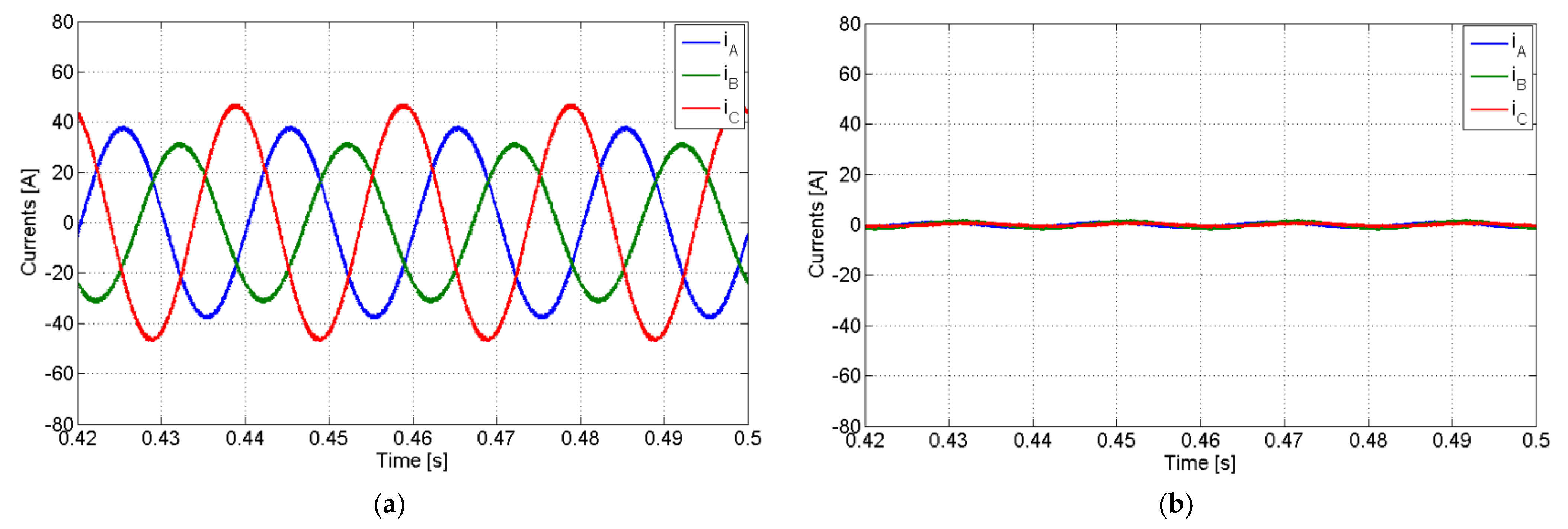
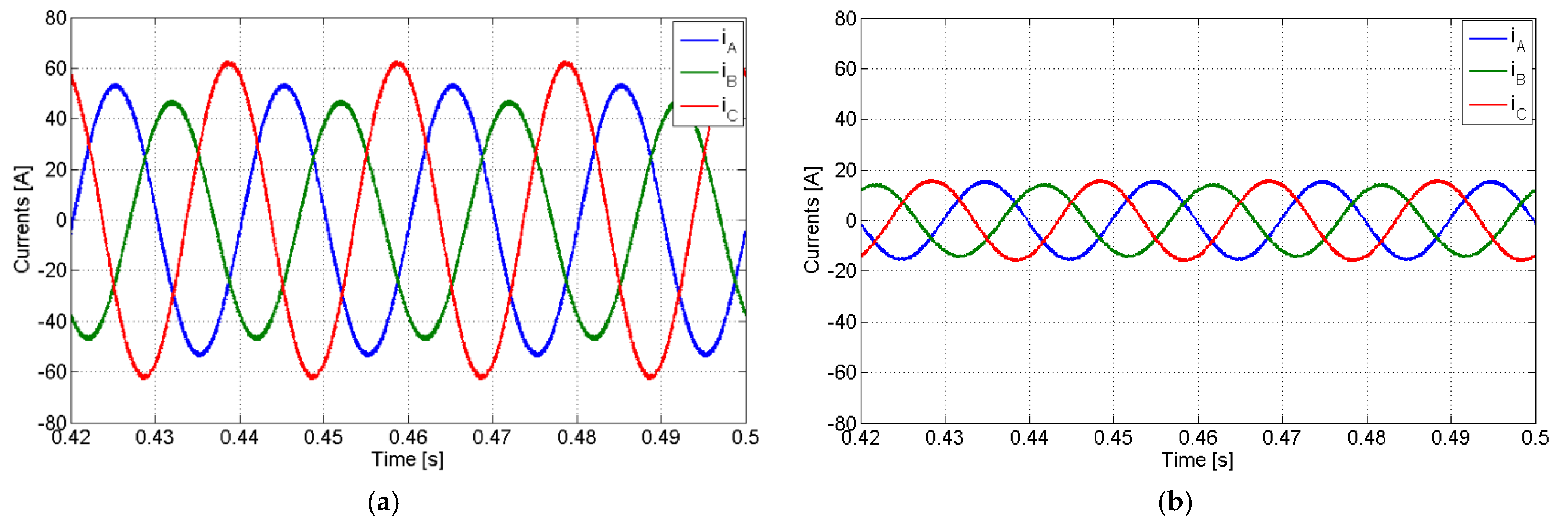
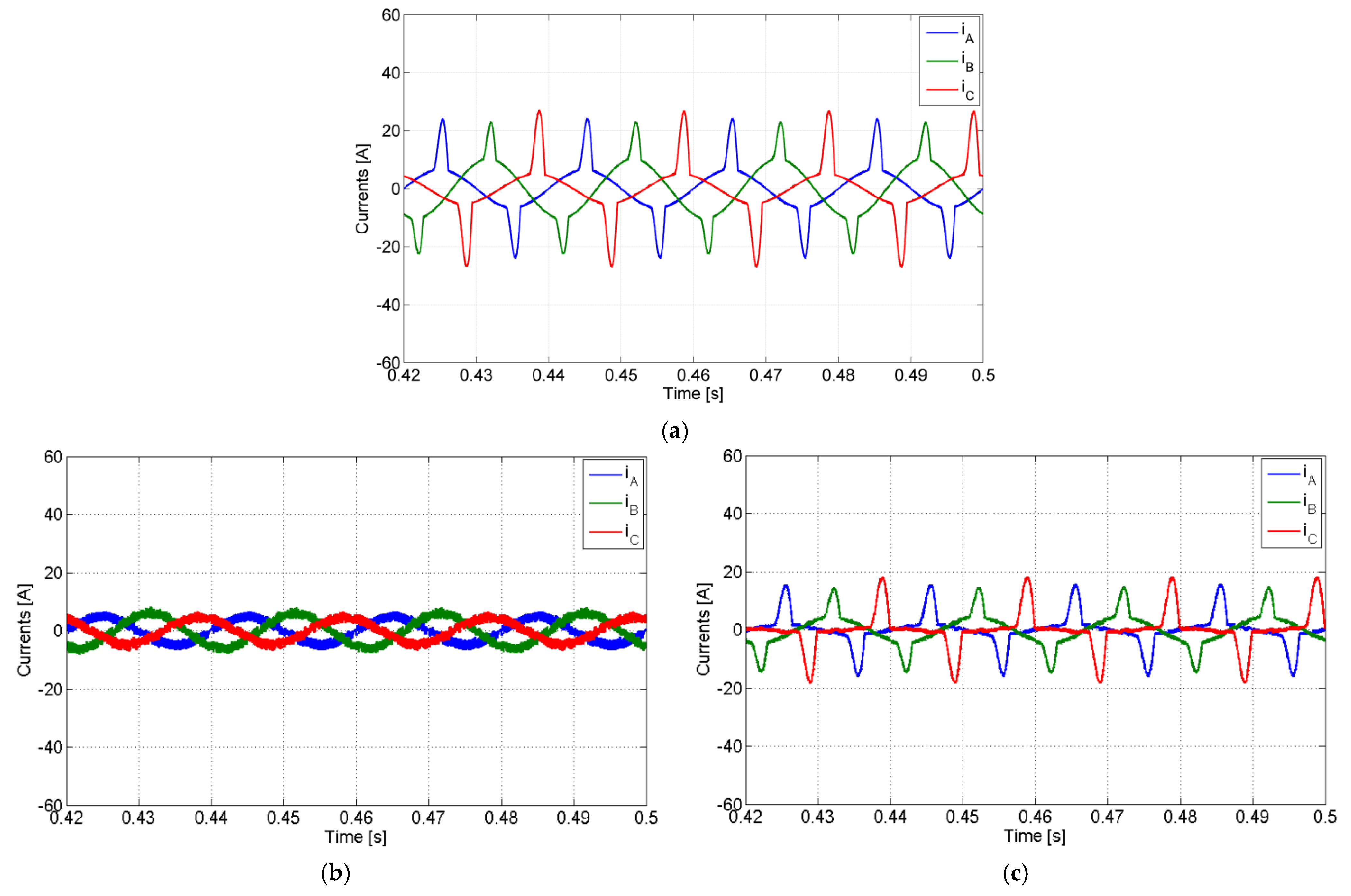
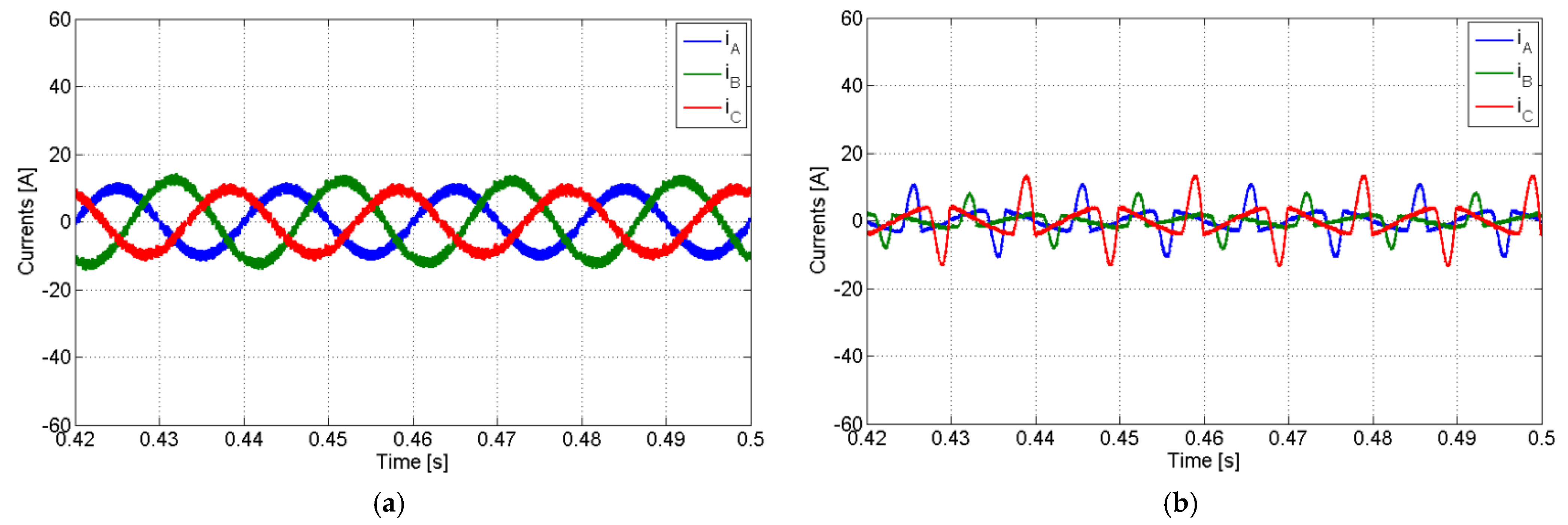
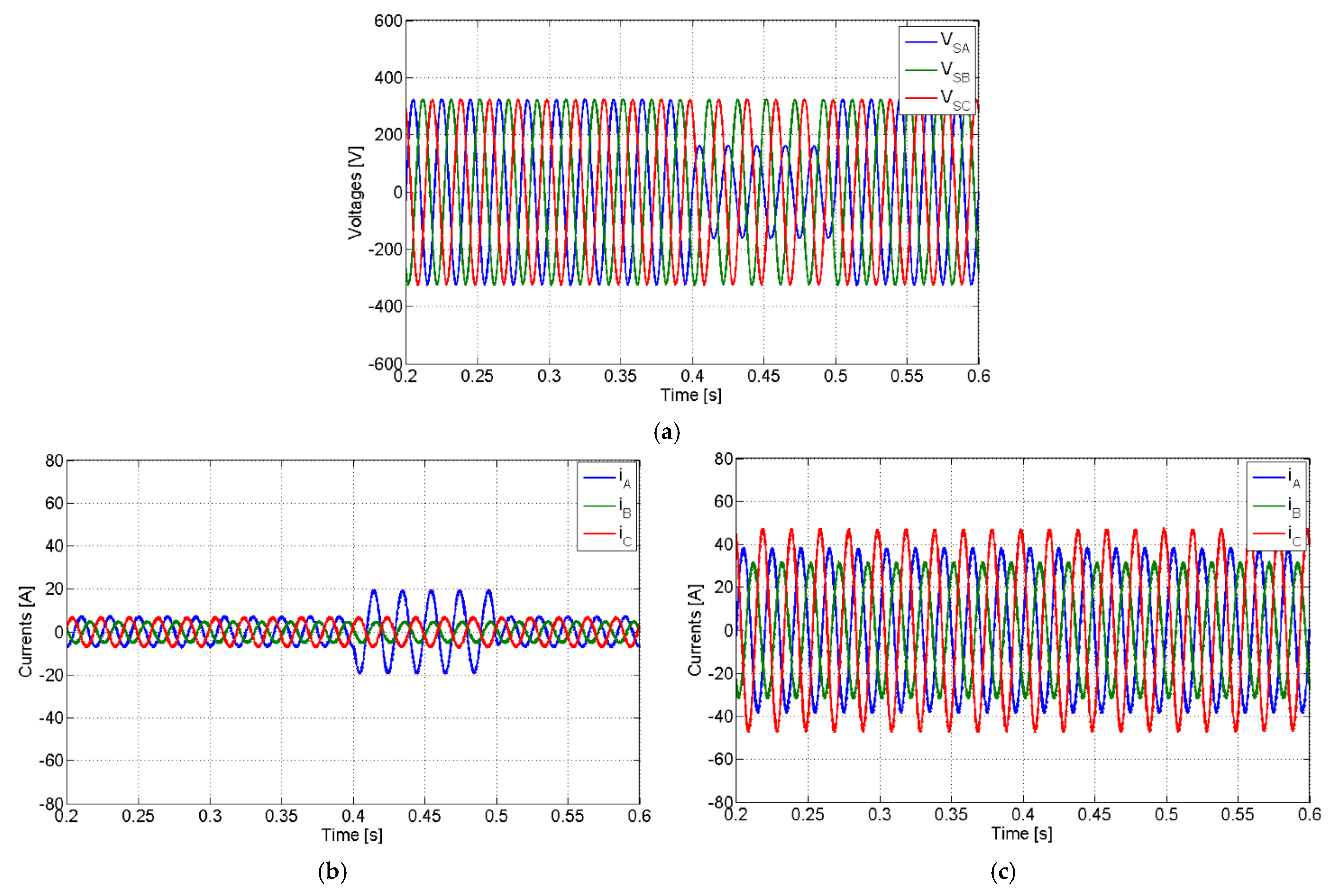
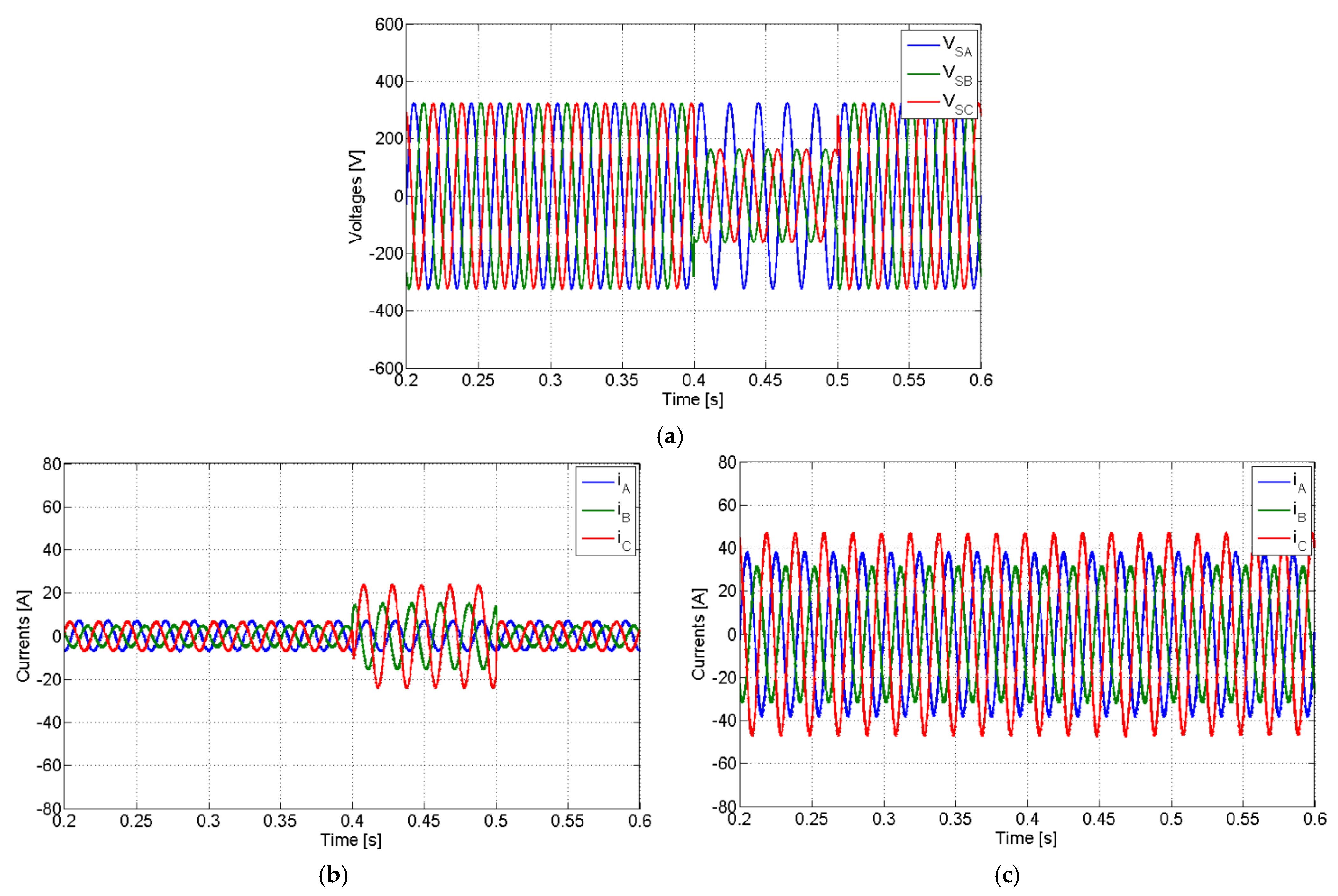
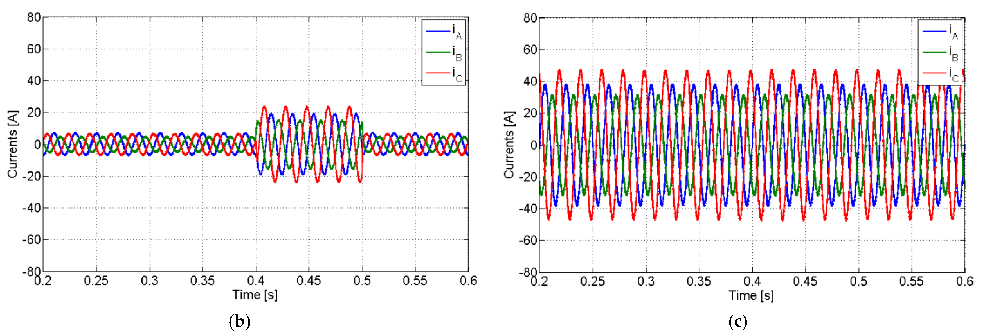
4. Simulation Results
- The subcompensation mode is when the generated power from the PV system is lower than the active load power;
- The full compensation mode is when the generated power from the PV system is equal to the active load power;
- The overcompensation mode is when the generated power from the PV system is higher than the active load power.
5. Discussion
6. Conclusions
Author Contributions
Funding
Conflicts of Interest
References
- BP. BP Statistical review of world energy. In Technical Report, 66th ed.; British Petroleum Company: London, UK, 2017. [Google Scholar]
- Obeidat, F. A comprehensive review of future photovoltaic systems. Sol. Energy 2018, 163, 545–551. [Google Scholar] [CrossRef]
- Barrero-González, F.; Pires, V.F.; Sousa, J.L.; Martins, J.F.; Milanés-Montero, M.I.; González-Romera, E.; Romero-Cadaval, E. Photovoltaic power converter management in unbalanced low voltage networks with ancillary services support. Energies 2019, 12, 972. [Google Scholar] [CrossRef] [Green Version]
- Romero-Cadaval, E.; Spagnuolo, G.; Franquelo, L.G.; Ramos-Paja, C.A.; Suntio, T.; Xiao, W.M. Grid-connected photovoltaic generation plants: Components and operation. IEEE Ind. Electron. Mag. 2013, 7, 6–20. [Google Scholar] [CrossRef] [Green Version]
- Ali Khan, M.Y.; Liu, H.; Yang, Z.; Yuan, X. A comprehensive review on grid connected photovoltaic inverters, their modulation techniques, and control strategies. Energies 2020, 13, 4185. [Google Scholar] [CrossRef]
- Hazari, M.R.; Jahan, E.; Mannan, M.A.; Das, N. Transient stability enhancement of a grid-connected large-scale PV system using fuzzy logic controller. Electronics 2021, 10, 2437. [Google Scholar] [CrossRef]
- Zeb, K.; Uddin, W.; Khan, M.A.; Ali, Z.; Ali, M.U.; Christofides, N.; Kim, H.J. A comprehensive review on inverter topologies and control strategies for grid connected photovoltaic system. Renew. Sustain. Energy Rev. 2018, 94, 1120–1141. [Google Scholar] [CrossRef]
- Wu, X.; Kerekes, T. Flexible active power control for PV-ESS systems: A review. Energies 2021, 14, 7388. [Google Scholar] [CrossRef]
- Yacamini, R. Power system harmonics: Part 3. Problems caused by distorted supplies. Power Eng. J. 1995, 9, 233–238. [Google Scholar] [CrossRef]
- Seguí-chilet, S.; Gimeno-sales, F.J.; Orts, S.; Alcañiz, M.; Masot, R. Selective shunt active power compensator in four wire electrical systems using symmetrical components. Electr. Power Compon. Syst. 2006, 35, 97–118. [Google Scholar] [CrossRef]
- Balda, J.C.; Oliva, A.R.; McNabb, D.W.; Richardson, R.W. Measurements of neutral currents and voltages on a distribution feeder. IEEE Trans. Power Deliv. 1997, 12, 1799–1804. [Google Scholar] [CrossRef]
- Huo, Y.; Gruosso, G. Ancillary service with grid connected PV: A real-time hardware-in-the-loop approach for evaluation of performances. Electronics 2019, 8, 809. [Google Scholar] [CrossRef] [Green Version]
- Maza-Ortega, J.M.; Mauricio, J.M.; Barragán-Villarejo, M.; Demoulias, C.; Gómez-Expósito, A. Ancillary services in hybrid AC/DC low voltage distribution networks. Energies 2019, 12, 3591. [Google Scholar] [CrossRef] [Green Version]
- Kavya Santhoshi, B.; Mohana Sundaram, K.; Padmanaban, S.; Holm-Nielsen, J.B.; KK, P. Critical review of PV grid-tied inverters. Energies 2019, 12, 1921. [Google Scholar] [CrossRef] [Green Version]
- Liang, X.; Andalib -Bin- Karim, C. Harmonics and mitigation techniques through advanced control in grid-connected renewable energy sources: A review. IEEE Trans. Ind. Appl. 2018, 54, 3100–3111. [Google Scholar] [CrossRef]
- Camilo, F.M.; Pires, V.F.; Castro, R.; Almeida, M.E. The impact of harmonics compensation ancillary services of photovoltaic microgeneration in low voltage distribution networks. Sustain. Cities Soc. 2018, 39, 449–458. [Google Scholar] [CrossRef]
- Uzum, B.; Onen, A.; Hasanien, H.M.; Muyeen, S.M. Rooftop solar PV penetration impacts on distribution network and further growth factors—A comprehensive review. Electronics 2021, 10, 55. [Google Scholar] [CrossRef]
- Exposto, B.; Monteiro, V.; Pinto, J.G.; Pedrosa, D.; Nogueiras Meléndez, A.A.; Afonso, J.L. Three-phase current-source shunt active power filter with solar photovoltaic grid interface. In Proceedings of the IEEE International Conference on Industrial Technology (ICIT), Seville, Spain, 17–19 March 2015; pp. 1211–1215. [Google Scholar]
- Ahmed, E.M.; Aly, M.; Elmelegi, A.; Alharbi, A.G.; Ali, Z.M. Multifunctional distributed MPPT controller for 3P4W grid-connected PV systems in distribution network with unbalanced loads. Energies 2019, 12, 4799. [Google Scholar] [CrossRef] [Green Version]
- Alam, M.J.E.; Muttaqi, K.M.; Sutanto, D. Alleviation of neutral-to-ground potential rise under unbalanced allocation of rooftop PV using distributed energy storage. IEEE Trans. Sustain. Energy 2015, 6, 889–898. [Google Scholar] [CrossRef] [Green Version]
- Weckx, S.; Gonzalez, C.; Driesen, J. Reducing grid losses and voltage unbalance with PV inverters. In Proceedings of the IEEE PES General Meeting, Conference & Exposition, National Harbor, MD, USA, 27–31 July 2014; pp. 1–5. [Google Scholar]
- Lin, F.; Tan, K.; Lai, Y.; Luo, W. Intelligent PV power system with unbalanced current compensation using CFNN-AMF. IEEE Trans. Power Electron. 2019, 34, 8588–8598. [Google Scholar] [CrossRef]
- Rafi, F.H.M.; Hossain, M.J.; Lu, J. Improved neutral current compensation with a four-leg PV smart VSI in a LV residential network. IEEE Trans. Power Deliv. 2017, 32, 2291–2302. [Google Scholar] [CrossRef]
- Callegari, J.M.S.; Cupertino, A.F.; Ferreira, V.d.N.; Pereira, H.A. Minimum DC-link voltage control for efficiency and reliability improvement in PV inverters. IEEE Trans. Power Electron. 2021, 36, 5512–5520. [Google Scholar] [CrossRef]
- Mohamed Hariri, M.H.; Mat Desa, M.K.; Masri, S.; Mohd Zainuri, M.A.A. Grid-connected PV generation system—Components and challenges: A review. Energies 2020, 13, 4279. [Google Scholar] [CrossRef]
- Goh, H.H.; Li, X.; Lim, C.S.; Zhang, D.; Dai, W.; Kurniawan, T.A.; Goh, K.C. Common-mode voltage reduction algorithm for photovoltaic grid-connected inverters with virtual-vector model predictive control. Electronics 2021, 10, 2607. [Google Scholar] [CrossRef]
- Zhang, L.; Sun, K.; Hu, H.; Xing, Y. A system-level control strategy of photovoltaic grid-tied generation systems for european efficiency enhancement. IEEE Trans. Power Electron. 2014, 29, 3445–3453. [Google Scholar] [CrossRef]
- Tsengenes, G.; Adamidis, G. Investigation of the behavior of a three phase grid-connected photovoltaic system to control active and reactive power. Electric Power Syst. Res. 2011, 81, 177–184. [Google Scholar] [CrossRef]
- Xiao, W.; El Moursi, M.S.; Khan, O.; Infield, D. Review of grid-tied converter topologies used in photovoltaic systems. IET Renew. Power Gener. 2016, 10, 1543–1551. [Google Scholar] [CrossRef] [Green Version]
- Pires, V.F.; Husev, O.; Vinnikov, D.; Martins, J.F. A control strategy for a grid-connected PV system with unbalanced loads compensation. In Proceedings of the 9th International Conference on Compatibility and Power Electronics, Caparica, Lisbon, Portugal, 24–26 June 2015; pp. 154–159. [Google Scholar]
- De Kooning, J.D.M.; Bozalakov, D.; Vandevelde, L. Discrete time domain modeling and control of a grid-connected four-wire split-link converter. Electronics 2021, 10, 506. [Google Scholar] [CrossRef]
- Shawky, A.; Ahmed, M.; Orabi, M.; Aroudi, A.E. Classification of three-phase grid-tied microinverters in photovoltaic applications. Energies 2020, 13, 2929. [Google Scholar] [CrossRef]
- Mandrioli, R.; Viatkin, A.; Hammami, M.; Ricco, M.; Grandi, G. A comprehensive AC current ripple analysis and performance enhancement via discontinuous PWM in three-phase four-leg grid-connected inverters. Energies 2020, 13, 4352. [Google Scholar] [CrossRef]
- Sunddararaj, S.P.; Srinivasarangan Rangarajan, S. An extensive review of multilevel inverters based on their multifaceted structural configuration, triggering methods and applications. Electronics 2020, 9, 433. [Google Scholar] [CrossRef] [Green Version]
- Colak, I.; Kabalci, E.; Bayindir, R. Review of multilevel voltage source inverter topologies and control schemes. Energy Convers. Manag. 2011, 52, 1114–1128. [Google Scholar] [CrossRef]
- Barrios, M.A.; Cárdenas, V.; Sandoval, J.M.; Guerrero, J.M.; Vasquez, J.C. A cascaded DC-AC-AC grid-tied converter for PV plants with AC-link. Electronics 2021, 10, 409. [Google Scholar] [CrossRef]
- Sastry, J.; Bakas, P.; Kim, H.; Wang, L.; Marinopoulos, A. Evaluation of cascaded H-bridge inverter for utility-scale photovoltaic systems. Renew. Energy 2014, 69, 208–218. [Google Scholar] [CrossRef]
- Madasamy, P.; Verma, R.; Rameshbabu, A.; Murugesan, A.; Umamageswari, R.; Munda, J.L.; Bharatiraja, C.; Mihet-Popa, L. Neutral point clamped transformer-less multilevel converter for grid-connected photovoltaic system. Electronics 2021, 10, 977. [Google Scholar] [CrossRef]
- Hammami, M.; Ricco, M.; Ruderman, A.; Grandi, G. Three-Phase Three-Level Flying Capacitor PV Generation System with an Embedded Ripple Correlation Control MPPT Algorithm. Electronics 2019, 8, 118. [Google Scholar] [CrossRef] [Green Version]
- Zanasi, R.; Tebaldi, D. Modeling control and robustness assessment of multilevel flying-capacitor converters. Energies 2021, 14, 1903. [Google Scholar] [CrossRef]
- Pires, V.F.; Cordeiro, A.; Foito, D.; Silva, J.F. Three-phase multilevel inverter for grid-connected distributed photovoltaic systems based in three three-phase two-level inverters. Sol. Energy 2018, 174, 1026–1034. [Google Scholar] [CrossRef]
- Lacerda, R.P.d.; Jacobina, C.B.; Freitas, N.B.d.; Méllo, J.P.R.A.; Cunha, M.F. Cascaded transformer symmetric single-phase multilevel converters with two DC sources. IEEE Trans. Ind. Appl. 2021, 57, 5157–5169. [Google Scholar] [CrossRef]
- Panda, A.K.; Suresh, Y. Performance of cascaded multilevel inverter by employing single and three-phase transformers. IET Power Electron. 2012, 5, 1694–1705. [Google Scholar] [CrossRef]
- Carlos, G.; Jacobina, C.; Méllo, J.; Oliveira, A. Four-wired dynamic voltage restorers based on cascade open-end winding transformers. In Proceedings of the Energy Conversion Congress and Exposition (ECCE), Cincinnati, OH, USA, 1–5 October 2017; pp. 5198–5205. [Google Scholar] [CrossRef]
- Lopez-Santos, O.; Jacanamejoy-Jamioy, C.A.; Salazar-D’Antonio, D.F.; Corredor-Ramírez, J.R.; Garcia, G.; Martinez-Salamero, L. A single-phase transformer-based cascaded asymmetric multilevel inverter with balanced power distribution. IEEE Access 2019, 7, 98182–98196. [Google Scholar] [CrossRef]
- Pires, V.F.; Foito, D.; Cordeiro, A. PV power conditioning system using a three-phase multilevel pulse width modulation inverter employing cascaded scott transformers. IET Power Electron. 2019, 12, 102–111. [Google Scholar] [CrossRef]
- Aljawary, Z.A.; de Pablo, S.; Herrero-de Lucas, L.C.; Martinez-Rodrigo, F. Local carrier PWM for modular multilevel converters with distributed PV cells and circulating current reduction. Energies 2020, 13, 5585. [Google Scholar] [CrossRef]
- Nguyen, M.H.; Kwak, S. Improved indirect model predictive control for enhancing dynamic performance of modular multilevel converter. Electronics 2020, 9, 1405. [Google Scholar] [CrossRef]
- Bayat, H.; Yazdani, A. A power mismatch elimination strategy for an MMC-based photovoltaic system. IEEE Trans. Energy Convers. 2018, 33, 1519–1528. [Google Scholar] [CrossRef]
- Barcellona, S.; Barresi, M.; Piegari, L. MMC-based PV single-phase system with distributed MPPT. Energies 2020, 13, 3964. [Google Scholar] [CrossRef]
- Haq, S.; Biswas, S.P.; Hosain, M.K.; Rahman, M.A.; Islam, M.R.; Jahan, S. A modular multilevel converter with an advanced PWM control technique for grid-tied photovoltaic system. Energies 2021, 14, 331. [Google Scholar] [CrossRef]
- Acharya, A.B.; Ricco, M.; Sera, D.; Teoderscu, R.; Norum, L.E. Performance analysis of medium voltage grid integration of PV plant using modular multilevel converter. IEEE Trans. Energy Convers. 2019, 34, 1731–1740. [Google Scholar] [CrossRef]
- Grandi, G.; Ostojic, D.; Rossi, C.; Casadei, D. A new multilevel conversion structure for grid-connected PV applications. IEEE Trans. Ind. Electron. 2009, 56, 4416–4426. [Google Scholar] [CrossRef]
- Kumar, N.; Saha, T.; Dey, J. Sliding-mode control of PWM dual inverter-based grid-connected PV system: Modeling and performance analysis. IEEE J. Emerg. Sel. Top. Power Electron. 2016, 4, 435–444. [Google Scholar] [CrossRef]
- Pires, V.F.; Martins, J.F.; Hao, C. Dual-inverter for grid-connected photovoltaic system: Modeling and sliding mode control. Sol. Energy 2012, 86, 2106–2115. [Google Scholar] [CrossRef]
- Wang, B.; Zhang, X.; Song, C.; Cao, R. Research on the filters for dual-inverter fed open-end winding transformer topology in photovoltaic grid-tied applications. Energies 2019, 12, 2338. [Google Scholar] [CrossRef] [Green Version]
- Muneer, V.; Bhattacharya, A. Peak power demand management by using SMC-controlled three-level CHB-based three-wire and four-wire SAPF. IEEE Trans. Ind. Inform. 2021, 17, 5270–5281. [Google Scholar]
- López, I.; Ceballos, S.; Pou, J.; Zaragoza, J.; Andreu, J.; Kortabarria, I.; Agelidis, V. Modulation strategy for multiphase neutral-point-clamped converters. IEEE Trans. Power Electron. 2016, 31, 928–941. [Google Scholar] [CrossRef]
- Zhang, L.; Yang, H.; Wang, K.; Yuan, Y.; Tang, Y.; Loh, W.K. Design methodology for three-phase four-wire T-type inverter with neutral inductor. CPSS Trans. Power Electron. Appl. 2021, 6, 93–105. [Google Scholar] [CrossRef]
- Méllo, J.P.R.A.; Jacobina, C.B.; Corrêa, M.B.d.R. Three-phase four-wire inverters based on cascaded three-phase converters with four and three Legs. IEEE Trans. Ind. Appl. 2017, 53, 5539–5552. [Google Scholar] [CrossRef]
- Kim, J.-H.; Sul, S.-K.; Enjeti, P.N. A carrier-based PWM method with optimal switching sequence for a multilevel four-leg voltage-source inverter. IEEE Trans. Ind. Appl. 2008, 44, 1239–1248. [Google Scholar] [CrossRef]
- Antoniewicz, K.; Jasinski, M.; Kazmierkowski, M.P.; Malinowski, M. Model predictive control for three-level four-leg flying capacitor converter operating as shunt active power filter. IEEE Trans. Ind. Electron. 2016, 63, 5255–5262. [Google Scholar]
- Guo, X.; Yang, Y.; Wang, B.; Blaabjerg, F. Leakage current reduction of three-phase z-source three-level four-leg inverter for transformerless PV system. IEEE Trans. Power Electron. 2019, 34, 2560–2569. [Google Scholar] [CrossRef]
- Bayhan, S.; Trabelsi, M.; Abu-Rub, H.; Malinowski, M. Finite-control-set model-predictive control for a quasi-z-source four-leg inverter under unbalanced load condition. IEEE Trans. Ind. Electron. 2017, 64, 2560–2569. [Google Scholar] [CrossRef]
- Utkin, V.I. Sliding Modes in Control Optimization; Springer: New York, NY, USA, 1981. [Google Scholar]
- Gao, W.; Hung, J. Variable structure control: A Survey. IEEE Trans. Ind. Electron. 1993, 40, 2–22. [Google Scholar]


| νβ/να | −3 | −2 | −1 | 0 | +1 | +2 | +3 |
|---|---|---|---|---|---|---|---|
| −2 | 13 | 15 | 15 | 14 | 16 | 16 | 18 |
| −1 | 13 | 13 | 12 | 14 | 17 | 18 | 18 |
| 0 | 11 | 10 | 10 | 0 | 1 | 1 | 2 |
| +1 | 9 | 9 | 8 | 5 | 3 | 4 | 4 |
| +2 | 9 | 7 | 7 | 5 | 6 | 6 | 4 |
| νo/να | −3 | −2 | −1 | 0 | +1 | +2 | +3 |
|---|---|---|---|---|---|---|---|
| −3 | 61 | 60, 62, 64 | 60, 62, 64 | 63 | 63 | 63 | 63 |
| −2 | 57, 59 | 56, 58, 15, 57 | 61, 63, 65 | 52, 55 | 53, 54 | 53, 54 | 53 |
| −1 | 13, 45, 47 | 13, 44, 45, 46, 48 | 44, 46, 48 | 14, 42 | 43, 49, 50 | 43, 49, 51 | 43, 49, 51 |
| 0 | 9, 11 | 7, 9, 10, | 7, 8, 10, 12 | 0 | 1, 3, 16, 17 | 1, 16, 18 | 2, 18 |
| +1 | 26, 27, 28 | 26, 27, 28 | 25, 26, 27 | 5, 19 | 20, 21, 22 | 4, 20, 21, 22, 23 | 4, 23, 24 |
| +2 | 36 | 35, 36 | 35, 36 | 29, 34 | 6, 30, 32 | 6, 30, 32, 33 | 31, 33 |
| +3 | 38 | 38 | 38 | 38 | 37, 40, 41 | 38, 40, 41 | 38 |
| νo/νβ | −2 | −1 | 0 | +1 | +2 |
|---|---|---|---|---|---|
| −3 | 62, 63, 64 | 60, 61 | 60, 61 | 60, 61 | 60, 61 |
| −2 | 15, 52, 53 | 54, 58, 59 | 55, 56, 57 | 55, 56, 57 | 55, 56, 57 |
| −1 | 14, 49 | 13, 48, 50, 51 | 42, 43, 46, 47 | 44, 45 | 44, 45 |
| 0 | 16 | 12, 17, 18 | 0 | 3, 8, 9 | 7 |
| +1 | 21, 23 | 21, 23 | 19, 22, 24, 26 | 4, 20, 25, 28 | 5, 27 |
| +2 | 29, 30, 31 | 29, 30, 31 | 29, 30, 31 | 32, 33, 35 | 6, 34, 36 |
| +3 | 37, 38 | 37, 38 | 37, 38 | 37, 38 | 39, 40, 41 |
| Vector | S11 | S12 | S13 | S14 | S21 | S22 | S23 | S24 |
|---|---|---|---|---|---|---|---|---|
| 4A | 1 | 0 | 0 | 1 | 0 | 0 | 1 | 0 |
| 4B | 1 | 1 | 0 | 1 | 0 | 1 | 1 | 0 |
| 20A | 0 | 0 | 0 | 0 | 0 | 0 | 1 | 0 |
| 20B | 0 | 0 | 0 | 1 | 0 | 0 | 1 | 1 |
| 20C | 0 | 1 | 0 | 0 | 0 | 1 | 1 | 0 |
| 20D | 0 | 1 | 0 | 1 | 0 | 1 | 1 | 1 |
| 20E | 1 | 0 | 0 | 0 | 1 | 0 | 1 | 0 |
| 20F | 1 | 0 | 0 | 1 | 1 | 0 | 1 | 1 |
| 20G | 1 | 1 | 0 | 0 | 1 | 1 | 1 | 0 |
| 20H | 1 | 1 | 0 | 1 | 0 | 0 | 0 | 0 |
| 20I | 1 | 1 | 0 | 1 | 1 | 1 | 1 | 1 |
| 20J | 1 | 1 | 1 | 1 | 0 | 0 | 1 | 0 |
Publisher’s Note: MDPI stays neutral with regard to jurisdictional claims in published maps and institutional affiliations. |
© 2022 by the authors. Licensee MDPI, Basel, Switzerland. This article is an open access article distributed under the terms and conditions of the Creative Commons Attribution (CC BY) license (https://creativecommons.org/licenses/by/4.0/).
Share and Cite
Fernão Pires, V.; Cordeiro, A.; Foito, D.; José Pires, A.; Hao, C.; Francisco Martins, J.; Castro, R. Compensation of Unbalanced Low-Voltage Grids Using a Photovoltaic Generation System with a Dual Four-Leg, Two-Level Inverter. Electronics 2022, 11, 320. https://0-doi-org.brum.beds.ac.uk/10.3390/electronics11030320
Fernão Pires V, Cordeiro A, Foito D, José Pires A, Hao C, Francisco Martins J, Castro R. Compensation of Unbalanced Low-Voltage Grids Using a Photovoltaic Generation System with a Dual Four-Leg, Two-Level Inverter. Electronics. 2022; 11(3):320. https://0-doi-org.brum.beds.ac.uk/10.3390/electronics11030320
Chicago/Turabian StyleFernão Pires, Vitor, Armando Cordeiro, Daniel Foito, Armando José Pires, Chen Hao, João Francisco Martins, and Rui Castro. 2022. "Compensation of Unbalanced Low-Voltage Grids Using a Photovoltaic Generation System with a Dual Four-Leg, Two-Level Inverter" Electronics 11, no. 3: 320. https://0-doi-org.brum.beds.ac.uk/10.3390/electronics11030320