
Research on an Urban Low-Altitude Target Detection Method Based on Image Classification


1
Research Center of Satellite, Harbin Institute of Technology, No. 92 Xidazhi Street, Nangang District, Harbin 150001, China
2
School of Electronics and Information Engineering, Harbin Institute of Technology, Harbin 150001, China
*
Author to whom correspondence should be addressed.
Electronics 2022, 11(4), 657; https://0-doi-org.brum.beds.ac.uk/10.3390/electronics11040657
Submission received: 14 January 2022
/
Revised: 15 February 2022
/
Accepted: 17 February 2022
/
Published: 19 February 2022
(This article belongs to the Special Issue Analog AI Circuits and Systems)
Abstract
:With the expansion of the civil UAV (Unmanned Aerial Vehicle) market, UAVs are also increasingly being used in illegal activities such as espionage and snooping on privacy. Therefore, how to effectively control the activities of UAVs in cities has become an urgent problem to be solved. Considering the urban background and the radar performance of communication signals, a low-altitude target detection scheme based on 5G base stations is proposed in this paper. A 5G signal is used as the external radiation source, the method of transceiver separation is adopted, and the forward-scattered waves are used to complete the detection of UAV. This paper mainly analyzes the principle of forward scattering detection in an urban environment, where the forward-scattered wave of a target is stronger than the backward-reflected wave and contains both height difference and midline height information on the target. Based on the above theory, this paper proposes a forward-scattered wave recognition algorithm based on YOLOv3-FCWImageNet, which transforms the forward-scattered wave recognition problem into a target detection problem and accomplishes the recognition of forward-scattered waves by using the excellent performance of algorithms in the field of image recognition. Simulation results show that FCWImageNet can distinguish two different low-altitude targets effectively, and realize the monitoring and classification of UAVs.
1. Introduction
In recent years, with the rapid rise of UAV high-tech enterprises such as DJI, and the further opening of low-altitude airspace, the civilian UAV market has further expanded. At present, UAVs are widely used in traffic monitoring, long-distance aerial photography, and other fields [1]. However, due to their portability, UAVs are also used by criminals in illegal fields such as privacy snooping, causing harm to public security [2]. Low-altitude targets mainly refer to “low altitude, slow speed, small flying targets”, which are difficult to detected by radar. Therefore, how to realize the effective detection and control of low-altitude small targets has become an urgent security problem.
Compared with traditional monostatic radar, bistatic radar separates the receiver from the transmitter and uses the forward-scattering characteristics of electromagnetic waves to detect low-altitude targets. When the target is in the forward-scattering area of the bistatic radar, the radar cross-section (RCS) of the target can be increased by more than 10 dB [3,4] and the echo signal strength is greatly enhanced, making small targets easier to detect. Therefore, bistatic radar is more suitable for the detection of small targets with relatively small RCS.
However, traditional bistatic radar needs large transmitters, which cause strong interference in the electromagnetic environment in the city. However, if the existing telecommunication signals are the city is used as the radar radiation source, it can not only effectively avoid electromagnetic pollution, but also save on cost. With the development of 5G, telecommunication signals have wider bandwidth, denser networking, and higher carrier frequency, which greatly optimizes the radar detection resolution and detection accuracy [5]. This makes 5G a good solution for urban low-altitude target detection. At the same time, with the development of artificial intelligence, machine learning has become widely used in image recognition, data classification, and other fields. If the echo signal is processed and AI is used to classify the UAVs, then an urban low-altitude target detection system including monitoring, identification, and classification can be built.
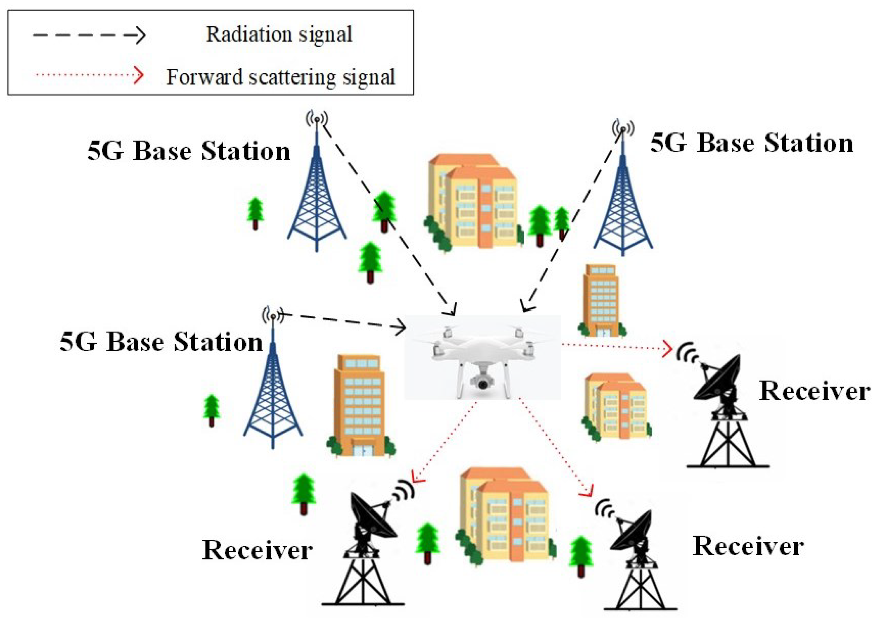
In this paper, a low-altitude target detection system based on 5G base stations is proposed that consists of a radar network composed of several 5G base stations and radar receivers (as shown in Figure 1). Using 5G signals as radar radiation sources, when the target passes through the baseline formed by 5G base stations and receivers, the target will radiate forward-scattered waves, which will be received by the radar receiver. When the target passes the baseline, the intensity of forward-scattered waves is theoretically more than 10 dB greater than backward-reflected waves, allowing the effective detection of low-altitude small targets. The classification of low-altitude targets can be accomplished by AI, which provides a powerful solution for the detection and classification of urban low-altitude targets.
2. Forward Scattering Detection
In a bistatic radar system, when the target is in the forward-scatter region, the echo intensity will increase by more than 10 dB, so when a small target is in the forward-scatter region, it is easier to detect. However, it is worth noting that the scattering range of the forward-scattering area is small, so to obtain a better forward-scattering signal, the target motion should be near the baseline [6].
When the target crosses the baseline of the receiver and 5G base station, the receiver will receive the forward-scattered signal of the target, which is called the radio holographic signal of the target, referred to as the holographic signal for short. After hologram signal processing, the height difference between the top and bottom edges and the midline feature of the target lateral projection profile can be obtained to complete the imaging of the target [7,8,9,10].
In order to better study the holographic signal of the target, the construction model is as follows.
2.1. The Holographic Signal Model of the Target
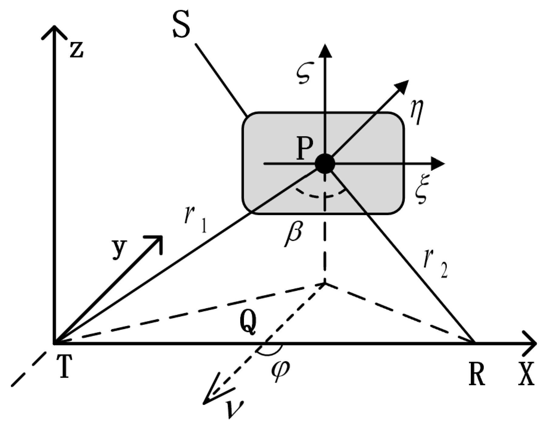
As shown in the Figure 2, a 5G base station is located at Point T, the receiver is located at point R, and the target is at point P. T is at the origin of the coordinate system , R is at , and the baseline length is B. The , , and axes of the coordinate system are parallel to the x, y, and z
axes of the coordinate system . The distance from the 5G base station to the target is , and the distance from the target to the receiver is . When the target is moving with a constant velocity v parallel to the plane, crossing the baseline is projected on the X-axis as point Q, and the included angle with the baseline is .
Theoretical research shows that the holographic signal of the target corresponds to the approximation of the Fresnel region of the forward scattering.
In the configuration above, the holographic signal of the target can be expressed as [11]:
where B is the baseline length and , is the electromagnetic wave wavelength. are the coordinates of the projection of R onto the plane . is the field distribution of profile aperture S. and represent the distances from the target to the 5G base station and the receiver. Under the assumption that the x-coordinate x changes very little, that is, when the target has a very small relative motion along the baseline, we think that is a time-independent parameter in an observation interval and is inversely proportional to the Fresnel radius.
When the target crosses the baseline at a uniform velocity v parallel to the plane at an angle to the baseline, the coordinate change of the target is:
where is the initial position of the target in frame . Based on the above hypothesis, the holographic signal representation of the target can be rewritten as:
where Q represents the influence of the geometric relationship between the target, the 5G base station, and the receiver on the holographic signal. Formula (3) contains the Doppler frequency change information caused by the target movement, which can estimate the position relationship between the target and the 5G base station and receiver. This is very important for the estimation of target location and target motion parameters, and is an important part of the estimation of the subsequent target motion trajectory.
According to (4), the amplitude of the holographic signal is inversely proportional to the product of the distances between the target and the 5G base station and the receiver, and inversely proportional to the electromagnetic wave length. The phase of the holographic signal depends on the length of the baseline and the height of the target.
mainly affects the phase information of . When given time t and , the phase change is mainly caused by the change in Doppler frequency caused by the target motion.
The in Formula (3) represents the complex contour function of the target, the amplitude of which includes the height difference information of the target profile, and the phase of which contains the midline information of the target, which is the main theoretical basis for obtaining the target shape by holographic signal, the expression is:
Let and be the height difference and the midline height of the target profile; then, the top and bottom edges of the target profile can be written as:
Then, (6) can be rewritten as:
where the projection profile can be obtained to complete the imaging of the target.
2.2. Target Feature Extraction
The above analysis shows that the holographic signal contains the profile information of the target; in the case of a small diffraction angle, (8) can be further integrated by ignoring the quadratic term to obtain [12]:
where . It is observed that the inverse Fourier variation after motion parameter compensation for (3) gives the relationship between and :
Further approximate treatment of Formula (10) can be obtained:
where (11) is the modulus value of the target complex contour function, and (12) is the phase value of the complex contour function.
According to (11), when (that is ), the complex contour function modulus of the target is equal to the height difference of the target, indicating that the height difference information of the target can be obtained by directly taking the modulus of the complex contour function when the target is in the plane and crosses the baseline.
2.3. Target Holographic Signal Simulation
2.3.1. Target Aircraft Model
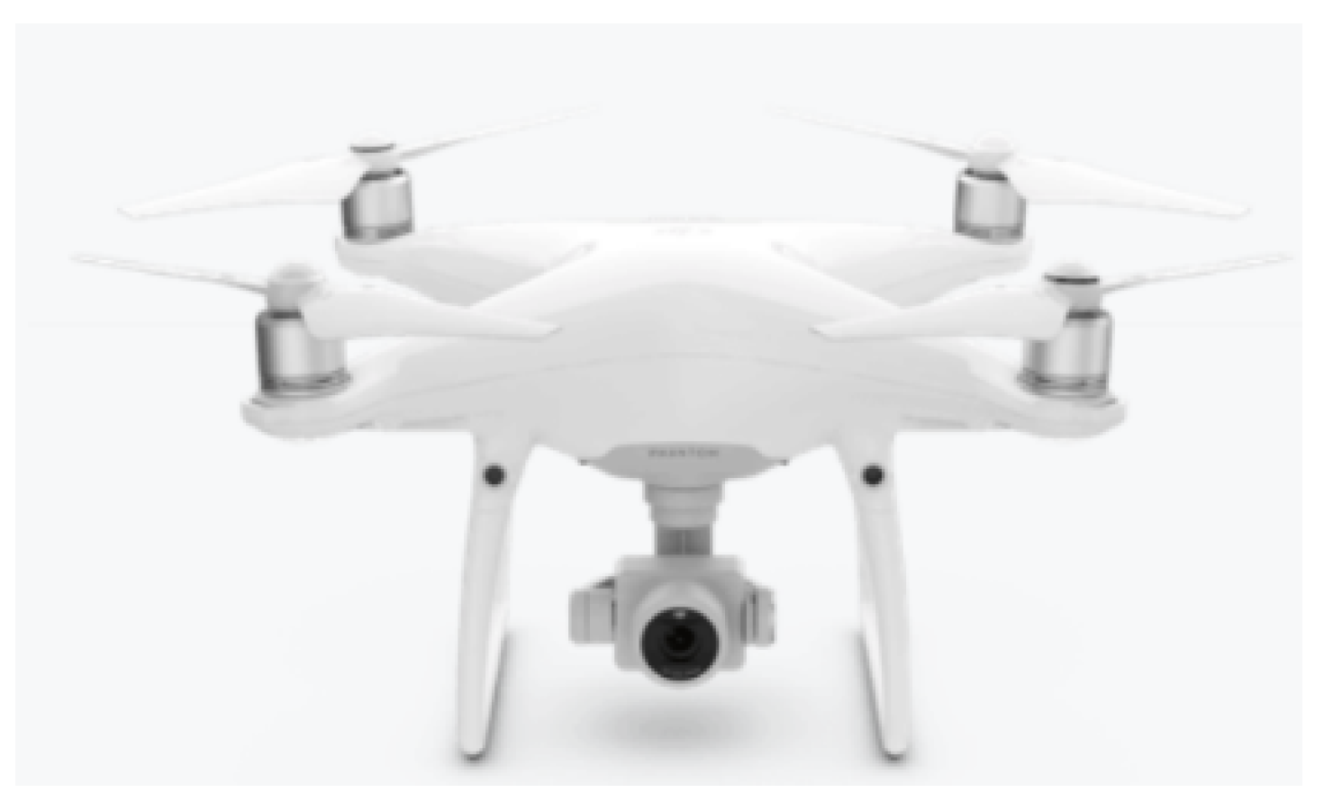
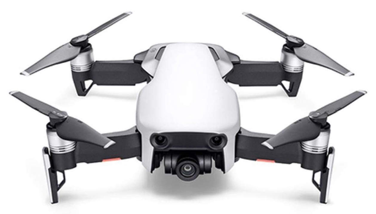
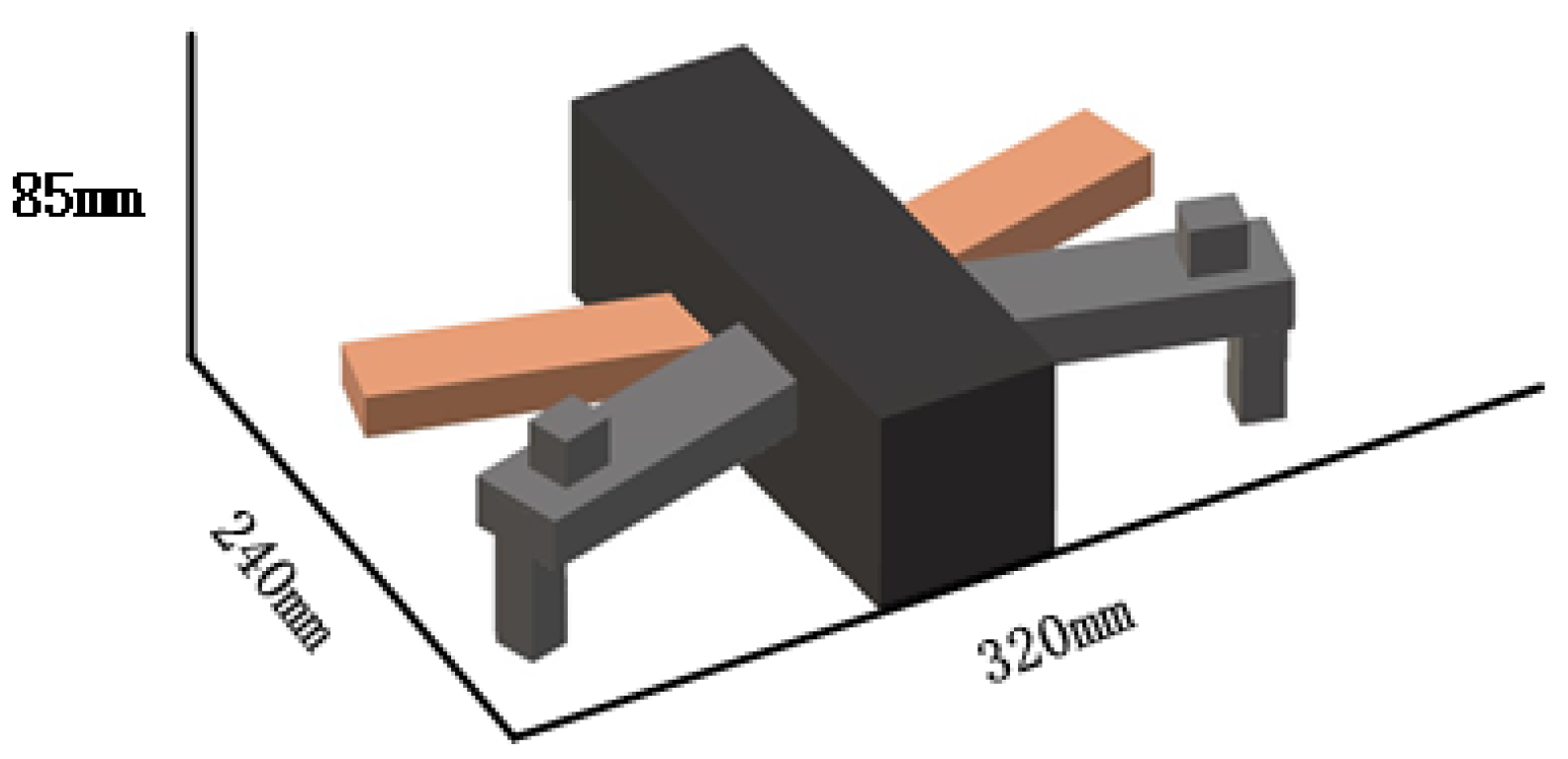
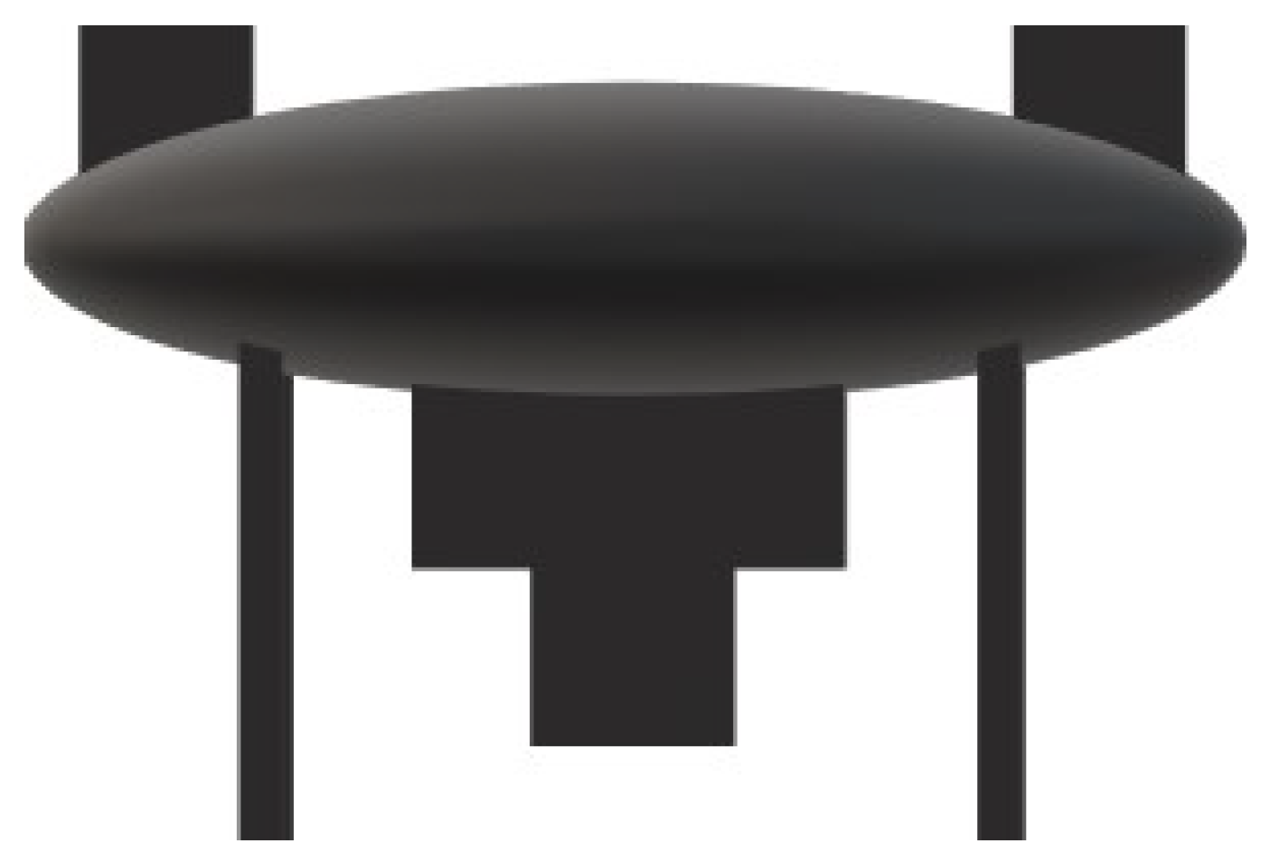
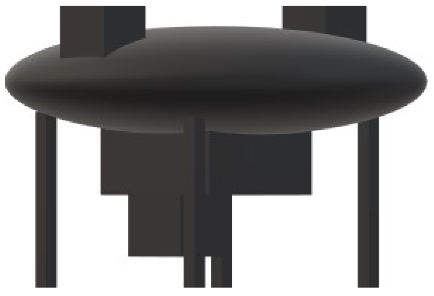
In order to better observe the holographic signals of different low-altitude targets, two UAVs with different shapes were adopted as the aircraft to be tested: the DJI Consumer UAV Phantom 4 advanced and the Mavic. The corresponding target model was established as shown in Figure 3 and Figure 4, and the above system was used to simulate the holographic signal of the target aircraft model.
2.3.2. Experimental Steps of Holographic Signal Simulation
Based on the above research, the steps for holographic signal simulation of the target aircraft are as follows:
- (1)
- Draw the upper and lower edge coordinates of the target contour in the target coordinate system according to the real geometric structure of the target, that is, the contour aperture of the target profile;
- (2)
- Set various target motion parameters, such as coordinates of the target, radiation signal wavelength, baseline length between the transmitter and receiver, total observation accumulation time, moving speed of the aircraft target, flight altitude, etc.;
- (3)
- Calculate the motion trajectory of the target according to its motion parameters and initial position, and calculate the corresponding and ;
- (4)
- (5)
- Finally, the holographic signal is calculated by integrating the above expressions.
2.3.3. Analysis of Holographic Signal Simulation Results
The following is an analysis of the holographic signal obtained when the two targets cross the baseline vertically. Figure 7 is the real part simulation of holographic signal of Target 1, and Figure 8 is the virtual part simulation.
By observing the above two images, we can find that the high frequency component of the holographic signal is rich, and the frequency is low when the target is near the baseline, but its amplitude is strong. When it is far from the baseline, its frequency gradually increases, and the time when the target crosses the baseline can be directly estimated from the graph (t = 0). When the target is near the baseline, the intensity of the holographic signal is high and easy to resolved, so the detection effect is better when the target is flying near the baseline. When the target is far from the baseline, the signal amplitude is small and it is difficult to separate it from the strong clutter.
Based on the above analysis, it can be found that the difference between Target 1 and Target 2 is mainly in signal frequency and amplitude. Target 1 increases rapidly, while Target 2 changes slowly, with significantly smaller vibration amplitude. This is mainly caused by the height difference and midline height difference between the two groups of aircraft. We can intuitively know from the above two pictures that these are two different aircraft targets, so we can know that the holographic signal has a good ability to distinguish different target aircraft.
3. Classification of UAVs Based on Machine Learning
Because the forward-scattered wave of the target contains the information of the height difference and centerline difference of the target, it belongs to the characteristic information of the target and can be used as a classification feature. Therefore, the UAV classification problem can be transformed into a classification problem of forward-scattering waves. Based on the above thinking, this paper creatively transforms the recognition problem of forward-scattering waves into a problem of target detection and classification in deep learning.
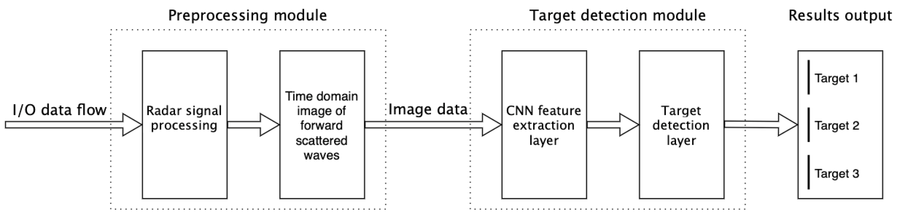
In this paper, a forward-scattering signal recognition algorithm named FCWImageNet is proposed. The forward-scattered wave recognition problem is transformed into ab image target detection problem, and the advanced achievements in the field of image recognition are fully utilized to improve the recognition ability of forward-scattered wave signals. The algorithm is mainly composed of two modules—the preprocessing module and the target detection module—as shown in Figure 11.
The preprocessing module mainly uses radar signal processing to extract the forward-scattering signal from the echo and obtain the corresponding time domain image for subsequent target recognition. The target detection module uses the time-domain image of the forward-scattered wave obtained by preprocessing it as the input, passes through the CNN feature extraction layer to obtain the abstract signal features, and then passes through the target detection layer to convert the abstract features into the corresponding target type as the output result. The end-to-end neural network model used in the target detection module is based on the YOLOv3 model.
Similar to the YOLOv3 model, the network structure of the target detection module of FCWImageNet mainly adopts the Darknet53 feature extraction network as the feature extraction network for forward-scattered waves. The main feature of Darknet53 is its use of residual networks. Residual networks are easy to optimize, and it is easier to improve their accuracy by increasing network depth. The residual block inside the network uses jump connection, which alleviates the gradient disappearance problem caused by increasing the network depth in deep neural networks. The output of each convolutional layer is processed with batch normalization, which increases the robustness and training speed of the model and prevents overfitting by replacing dropout.
The data used in this paper are self-made datasets, which mainly select two UAV products with high market share and construct simplified 3D models according to their real parameters. Because the attitude of the UAV is random, we hope that this deep learning model can complete the target classification no matter what angle the UAV passes through the baseline. Therefore, this dataset is composed of target silhouettes from different angles (mainly because different silhouettes cause different forward scattering signals)
Figure 12 and Figure 13 are the profiles at and . According to the actual application scenario, we chose the angle range of as 45–135. For each target, a forward-scattering sampling signal including I/Q was obtained every 0.1 degree of rotation as the signal to be classified. The whole dataset contains 3600 data points, of which 70% were used for training and 30% for testing.
3.1. UAV Classification Experiment Based on Machine Learning
The real and imaginary waveforms of the target holographic signal and the profile of the target contain all the information needed to judge the type of the targets. Therefore, this paper establishes three datasets to train and verify whether these three sets can be used as eigenvalues of UAV classification.
Considering the influence of the target motion state on the forward-scattered signal, holographic signal simulation was carried out for the target crossing the baseline with different angles of . The variation range of angle was set from to , and the interval was . Each target can obtain 90 waveforms of real and imaginary parts of the holographic signal. The height difference and midline information of the target can be separated from the data of real and imaginary parts by Formulas (9) and (10); then, the profile of the target can be restored. Each target dataset consists of three sub-datasets—real waveform, imaginary waveform, and contour image subsets—each with 90 different angles of data.
The AI platform ModelArt was used to complete the model construction. Three datasets were trained using the TensorFlow-based image classification framework to explore whether holographic signals can be used to classify low-altitude targets
3.2. Classification Result Analysis of UAVs Based on Machine Learning
Based on the above research, the image classification model is trained for the three data sets, and the results are shown in Table 1.
It can be observed that the accuracy of classification of the three datasets exceeds 97%, and the accuracy of contour image classification reaches 100%, which shows that the classification of the target aircraft can be realized by using the real and imaginary parts of the holographic signal and the reconstructed profile. The recognition accuracy of the target’s reconstructed profile is the highest, mainly because the target profile of different aircraft is quite different. The reason why the recognition rates of the real part and imaginary part are lower than that of the contour is that the sizes of the two kinds of targets are similar and the numerical difference between the height difference and the midline height is small, so it is difficult for the machine to distinguish through the waveform directly. When the target size difference is large, using only the imaginary and real parts of the waveform can also allow better classification of UAVs.
Due to the limited data, the accuracy and other parameters of this model do not reach the optimal value. With further supplementation and expansion of data, a better machine-learning model for UAV classification using forward-scattered waves can be obtained.
4. Conclusions
With the expansion of the UAV market, UAV detection in complex cities has become an urgent problem to be solved. In this paper, a scheme for target detection and classification in an urban environment is proposed, combining the signal characteristics of high frequency, high bandwidth, and high coverage of 5G signals with the characteristics of the target’s forward-scattering signal. A radio signal recognition algorithm based on deep learning and forward scattering is also proposed in this paper.
In this paper, the theoretical derivation verifies that the forward-scattering signal contains the target height difference and centerline information, and the forward-scattering wave signal of the target was obtained by experimental simulation. Because the forward scattering signal of the target contains the characteristic information of the target, the deep neural network FCWImageNet model for target classification based on the forward scattering signal was creatively proposed and used to complete the target classification problem with the background set in this paper.
Based on the YOLOv3 model, the algorithm first extracts the time-domain diagram of the forward-scattering signal from the I/Q sampling signal by using traditional digital signal processing methods, and then transforms the problem of radio signal recognition into a problem of target detection in the field of image recognition. The simulation verifies the classification of the real part waveform, the imaginary part waveform, and the contour recombination of the holographic signal; the accuracy of distinguishing two different UAVs reached more than 97% with our homemade dataset, which proves the feasibility of using the model as a UAV classification. However, this is still a preliminary attempt. In the future, we will further study which neural network model is most suitable for the characteristics of radio signals by combining more dimensional features of forwarding scattered signals. This paper verifies the feasibility of the scheme and the effectiveness of the FCWImageNet algorithm, and also provides a new idea for UAV detection and classification in urban environments.
Author Contributions
Conceptualization, H.J. and G.X.; methodology, H.J., G.X., Y.W. and Z.W.; software, H.J., Y.W. and G.X.; validation, G.X. and Z.W.; formal analysis, H.J. and G.X.; investigation, Z.W.; resources, Z.W.; data curation, G.X.; writing—original draft preparation, H.J. and G.X.; writing—review and editing, H.J., G.X., Y.W. and Z.W.; visualization, Z.W.; supervision, Z.W. All authors have read and agreed to the published version of the manuscript.
Funding
This work was supported by the National Natural Science Foundation of China (Grant No. 61871157, 62071145).
Data Availability Statement
The dataset is available on request from the corresponding author.
Acknowledgments
Thanks to the Harbin Institute of Technology for help with this project.
Conflicts of Interest
The authors declare no conflict of interest.
References
- Gupta, H.; Verma, O.P. Monitoring and surveillance of urban road traffic using low altitude drone images: A deep learning approach. Multimed. Tools Appl. 2021, 1–21. [Google Scholar] [CrossRef]
- Cheng, S. Research on Detection Method of Low Slow Small Target Based on 5G Signal of External Radiation Source Radar. Master’s Thesis, Xidian University, Xi’an, China, 2019. [Google Scholar]
- Xu, D.-M.; Zhang, H.W. Overview of radar low slow small target Detection technology. Mod. Def. Technol. 2018, 46, 148–155. [Google Scholar]
- Hao, Z.; Guoping, H.; Junpeng, S. Analysis and Prospect of low-Altitude Target Detection Technology. Fire Command Control 2015, 40, 5–9. [Google Scholar]
- Wu, Y.; Guo, W.; Liu, J.; Yang, B.; Ba, L.; Jin, H. Low Altitude Target Detection Technology Based on 5G Base Station. In Artificial Intelligence for Communications and Networks; Shi, S., Ye, L., Zhang, Y., Eds.; Springer International Publishing: Cham, Switzerland, 2021; pp. 381–389. [Google Scholar]
- Ma, H.; Zhu, T.; Xu, J. SISAR holographic signal representation based on space-based emission source and its imaging method. In System Engineering and Electronic Technology; Feral House: Port Townsend, WA, USA, 2010; pp. 32–36. [Google Scholar]
- Chao, Z.; Canyan, Z.; Cheng, H.; Tao, Z. Accuracy analysis of SISAR imaging algorithm in forward scatter radar. In Proceedings of the 2012 International Conference on Wireless Communications and Signal Processing (WCSP), Huangshan, China, 25–27 October 2013. [Google Scholar]
- Luo, B.F.; Zhang, G.J.; Zhang, S.H. The expression and simulation of radio holographic signal for the moving object in SISAR. J. Electron. Inf. Technol. 2003, 19, 187–191. [Google Scholar]
- Luo, B.F.; Zhang, S.H.; Zhang, T.; Luo, Y.J. Shadow Profile Midline Phase Reconstruction and Its Identification Features Extraction for SISAR. Acta Electron. Sin. 2004, 32, 368–372. [Google Scholar]
- Zhang, S.; Zhang, G.; Luo, B. Simulation study of moving target holographic Signal in SISAR. J. Radio Sci. 2004, 19, 187–191. [Google Scholar]
- Chapurskiy, V.V.; Sablin, V.N. SISAR: Shadow Inverse synthetic aperture radiolocation. In Proceedings of the Record of the IEEE 2000 International Radar Conference [Cat. No. 00CH37037], Alexandria, VA, USA, 12 May 2000; pp. 322–328. [Google Scholar]
- Yang, J.; Lu, B.; Bian, L. New system radar technology for detecting low and Slow small targets. Electron. Technol. Softw. Eng. 2018, 2018, 101. [Google Scholar]
Figure 1.
Low-altitude target detection system based on 5G base stations.

Figure 2.
Holographic signal model.

Figure 3.
Phantom 4 advanced.

Figure 4.
Mavic.

Figure 5.
Phantom 4 advanced simulation model.

Figure 6.
Mavic simulation model.

Figure 7.
Real part simulation of Target 1 holographic signal.

Figure 8.
Virtual part simulation of Target 1 holographic signal.

Figure 9.
Real part simulation of Target 2 holographic signal.

Figure 10.
Virtual part simulation of Target 2 holographic signal.

Figure 11.
FCWImageNet algorithm structure.

Figure 12.
Crossing the baseline at .

Figure 13.
Crossing the baseline at .


Table 1.
Machine-learning model training results.
| Accuracy | Recall | Precision | F1 | |
|---|---|---|---|---|
| Real waveform | 0.986 | 0.986 | 0.987 | 0.986 |
| Imaginary waveform | 0.973 | 0.973 | 0.973 | 0.973 |
| Reconstructed profile | 1.000 | 1.000 | 1.000 | 1.000 |
Publisher’s Note: MDPI stays neutral with regard to jurisdictional claims in published maps and institutional affiliations. |
© 2022 by the authors. Licensee MDPI, Basel, Switzerland. This article is an open access article distributed under the terms and conditions of the Creative Commons Attribution (CC BY) license (https://creativecommons.org/licenses/by/4.0/).
Share and Cite
MDPI and ACS Style
Jin, H.; Wu, Y.; Xu, G.; Wu, Z. Research on an Urban Low-Altitude Target Detection Method Based on Image Classification. Electronics 2022, 11, 657. https://0-doi-org.brum.beds.ac.uk/10.3390/electronics11040657
AMA Style
Jin H, Wu Y, Xu G, Wu Z. Research on an Urban Low-Altitude Target Detection Method Based on Image Classification. Electronics. 2022; 11(4):657. https://0-doi-org.brum.beds.ac.uk/10.3390/electronics11040657
Chicago/Turabian StyleJin, Haiyan, Yuxin Wu, Guodong Xu, and Zhilu Wu. 2022. "Research on an Urban Low-Altitude Target Detection Method Based on Image Classification" Electronics 11, no. 4: 657. https://0-doi-org.brum.beds.ac.uk/10.3390/electronics11040657
Note that from the first issue of 2016, this journal uses article numbers instead of page numbers. See further details here.