1. Introduction
High voltage is used to reduce transmission losses [
1,
2]. Compared with alternating current (AC), DC data transmission over long distances incurs less loss. The use of direct current (DC) to connect separate power grids can lessen the impact of transmission losses and increase the dependability of long-distance power transmission [
2]. DC is gradually gaining popularity because it leads to a more reliable power grid. In DC systems, restricting and blocking DC is mandatory [
3].
Direct current (DC) fault current must be rapidly handled to prevent harm to neighbouring systems [
4]. It is essential that one of the defences (SFCL) is built out of a superconducting material [
5]. The SFCL increases in speed when a superconducting material is quenched. Typically, an SFCL’s 0 R value means zero power loss [
6]. When the fault current is interrupted by the SFCL’s superconducting component shaking [
7], the SFCL is functioning as intended. Before an SFCL can be used in a real-world power system, more superconducting components are needed [
8]. Because of this, SFCLs have been developed, and studies on SFCL triggers, double quench, and trans-formers have been conducted [
9].
Installing an SFCL eliminates the requirement to switch off the main distribution board’s circuit breaker [
10]. Therefore, it will likely significantly impact the economy [
11]. It may be more cost effective to use an SFCL rather than to replace the circuit breaker. SFCL construction is underway in Europe [
12] on transmission lines and in Japan [
13] on distribution lines. SFCLs with 22.9 kV and 154 kV are now being built in South Korea [
14].
Due to rising power consumption and generation, fault currents in power systems have expanded along with industrialization and economic development. The cost of replacing equivalent electrical equipment may increase as fault currents increase the breaking capacity of existing circuit breakers. A short circuit in the power system reduces voltage and disrupts the bus’s stability. The subject of research is the use of superconducting fault current limiters (SFCLs) to mitigate fault current in electrical networks [
15].
Large SFCL capacities are not typically the most cost-effective choice, but they limit current more effectively than less expensive options. DC systems are difficult to block since there is no zero point. Arcing and blockage can be avoided if the fault current is limited to safe levels. Breakers are more reliable when SFCL is used to lower the fault current.
Every electrical grid relies on three primary components: power generation, transmission, and distribution. You can put limits on those three things by employing either SFCL or plain old FCL. It can be used if the fault current generation in the system becomes excessive. The voltages used by transmission lines are higher than those used by power plants and distribution networks. Despite the fact that some SFCL structures can be constructed for HV usage, it is anticipated that SFCL will be employed largely for low-voltage uses due to the insulating issue in HV applications.
The total cost of ownership (TCO), together with costs of development, maintenance, the recovery process, AC loss, volume, and weight, must be taken into account while making plans for or implementing SFCL. Several interesting new constructions have emerged in recent years. These include RSFCLs, HSFCLs, and SISFCLs. These SFCL models have been deployed to operational grids for continuous monitoring. In the long run, these SFCLs are likely to prove useful. Extensive testing has shown that SFCL has the potential to significantly lower fault currents in the presence of a real-world problem.
This research conducted short-circuit studies on a DC SFCL that gets one of its two triggering current levels from a transformer. To study DC SFCLs, a transformer was needed. The DC current limiting capabilities of CLR were investigated by conducting short-circuit tests on a transformer-based DC SFCL. This study contributes the following:
Using an equivalency circuit analysis and a short circuit test, we studied an SFCL transformer with an extra-connected non-isolated circuit.
SFCL performance was explored for I, V, and P. Peak cutting, quench sequence, and more for operation characteristics.
In this paper, we investigate how a flux-coupled type superconducting fault current limiter (SFCL) with a parallel connection between two windings in a DC system controls fault current.
The major goal of this strategy is that two coils will be connected in parallel, and a superconducting element (SE) will be connected in series with the secondary coil. Magnetic fluxes generated by each coil ensure that the voltage produced in the coil remains at zero even if the fault did not occur. The flux-coupled type SFCL has identical roles and responsibilities in DC systems as it does in AC systems.
As a consequence of faults in the superconducting element, resistance builds up, which prevents magnetic fluxes from cancelling each other. In this way, the fault current is restricted by producing some voltages by both coils.
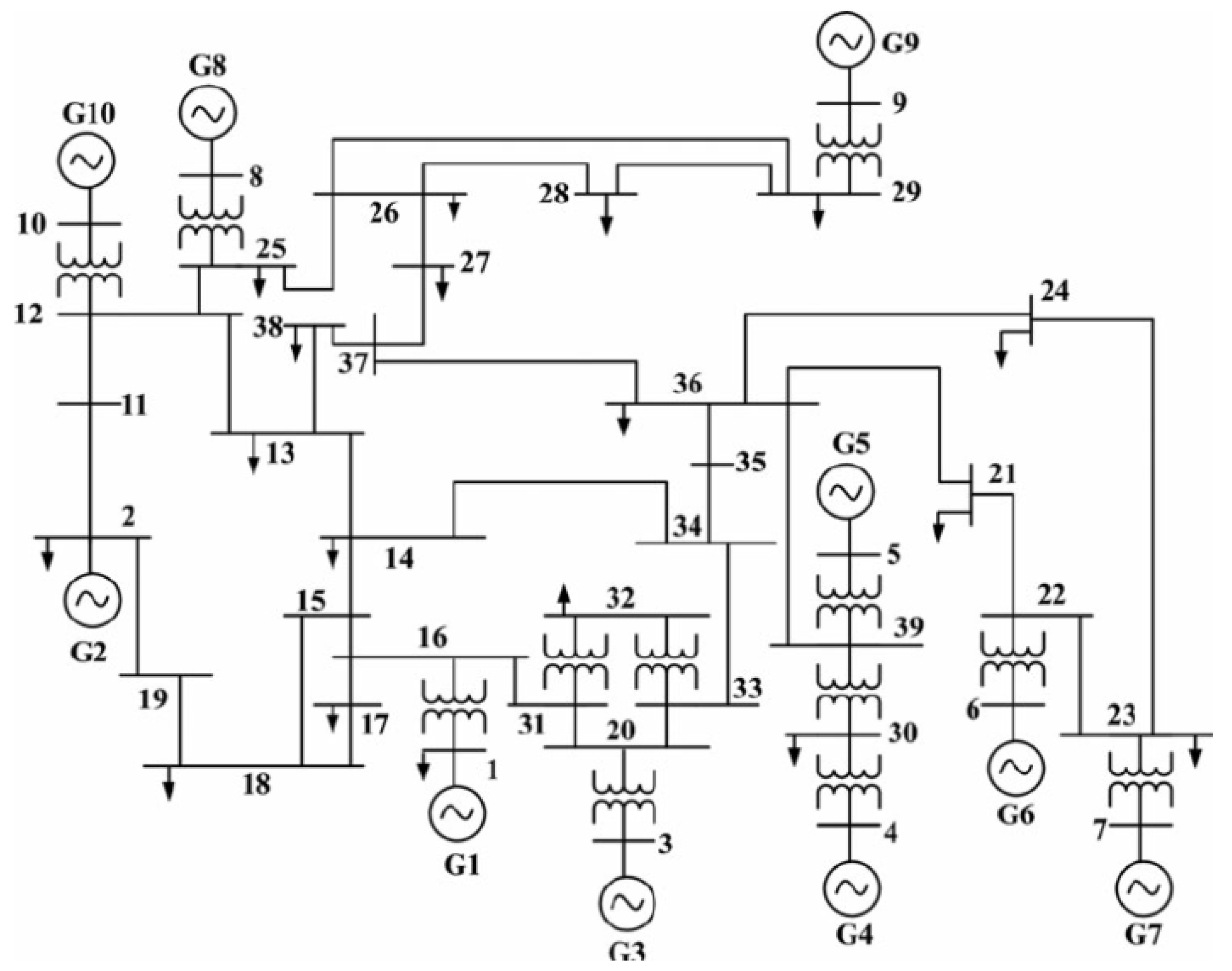
To check the efficiency of the flux-coupled type SFCL, the IEEE 39 bus system is used for testing by using different values of resistance and inductance to check the system’s stability.
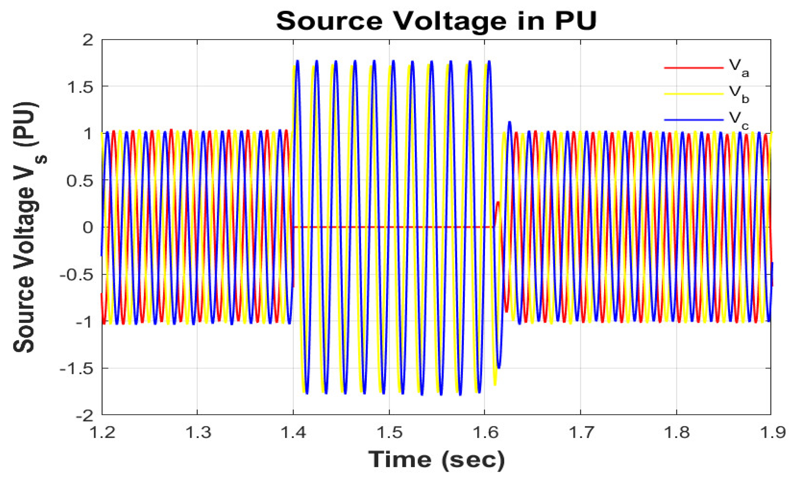
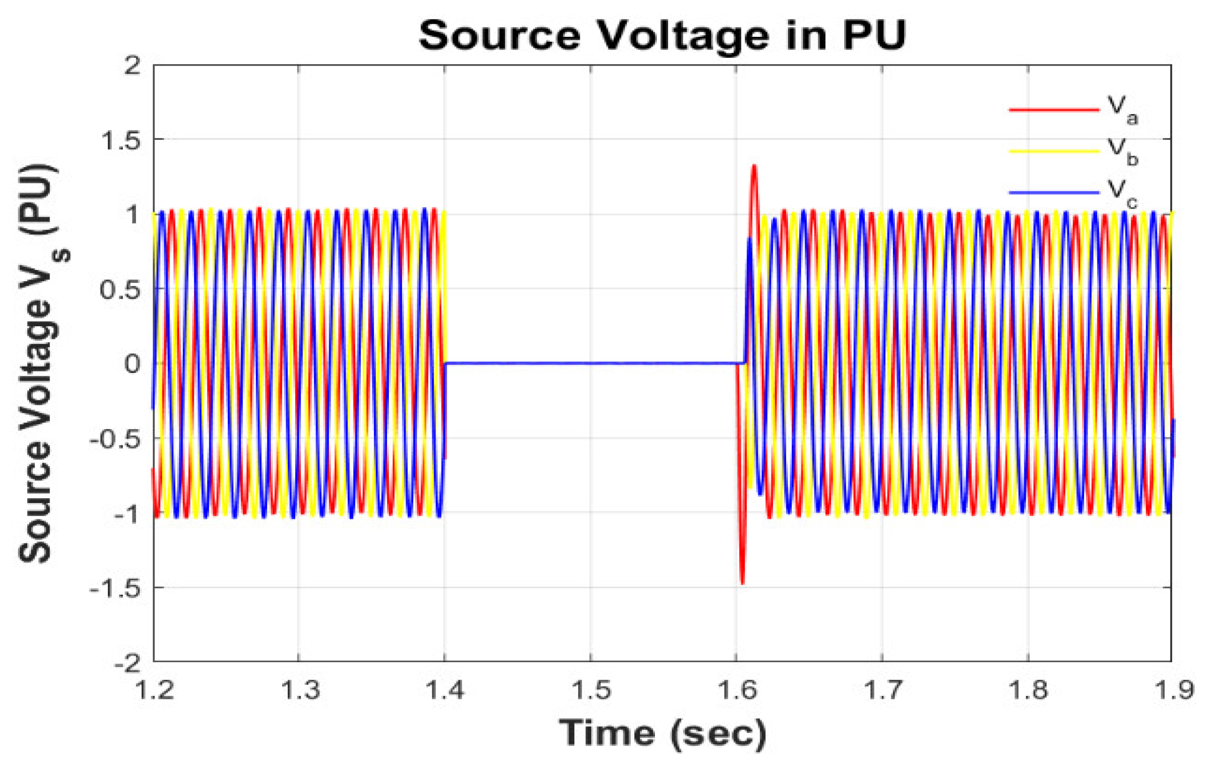
In the test conditions, line-to-ground and three-phase fault are also studied. The injected voltages for specific intervals of line-to-ground and three-phase fault are provided to the system. SFCL restricts the voltage within the desired magnitude to make the load voltage constant. In this way, the system response is stable.
We investigate how a DC system’s fault current can be controlled using a flux-coupled superconducting fault current limiter (SFCL). There are two coils in parallel in a flux coupler SFCL, and the secondary coil has a superconducting element in series with it. RSC1 and RSC2 are linked together serially, while RSC1 and CLR are linked in parallel. Two superconducting elements are used in the DC SFCL to distribute the superconductor mass uniformly. A CLR reduces the amount of energy needed to keep a superconductor operating. RSC1 acts as a voltage divider when a fault current is present. It is through RSC1 and RSC2 that the fault current is gradually reduced. For this research, a robust IEEE 39 bus system was used to guarantee reliable operation. Together, capacitance and inductance affect the voltage, current, and power waveform. Over both a ground fault and a three-phase fault, we recorded significant voltage drops and spikes. By injecting a certain voltage during a sag/swell, a fault can be cleared and the load voltage stabilised. The results of contrasting the current study with the prior state of the art are shown in
Table 1.
This paper has five sections.
Section 1 is the introduction and context,
Section 2 is a critical analysis of the literature,
Section 3 is the research technique,
Section 4 offers the results, and
Section 5 provides conclusions.
2. Related Work
DC power transmission is gaining popularity as a high-efficiency alternative [
1,
2,
3]. This is true in renewable energy transmission, HVDC, and DC microgrids. No natural zero crossing of fault current makes DC power system safety and dependability harder to assure. DCCBs are the best solution for fault prevention [
4,
5,
6].
Figure 1 [
7] shows a hybrid DCCB network topology.
Due to the quick increase in fault current and the DCCBs’ limited ultimate breaking capability, it is impossible to guarantee that protective systems will function in the case of a DC fault. So that DCCBs can successfully interrupt the fault current, the fault current must be limited [
8]. Current-limiting inductors are frequently used in series with hybrid DCCB to reduce fault current [
8,
9]. Excessive inductance can slow down the responsiveness of a DC system and diminish its stability, while small inductance has a negligible effect on current. A resistive-type superconducting fault current limiter (R-SFCL) [
10,
11] is another practical method for limiting fault current in a DC system. In addition, the metal oxide arrester (MOA) is typically used to soak up any residual energy in the system following an interruption. However, there are some risks associated with arrester use, such as (1) internal partial discharge and (2) arresters falling apart forcibly under excessive weights [
12].
As an alternative to these more traditional forms of protection, superconducting fault current limiters (SFCLs) can be used since they have no resistance during normal-current operation, suffer no loss during fault-current faults, and do not need any extra fault detection or operational circuitry. This is why several different SFCL concepts and schemes have been presented and technically proven over the course of the last few decades [
11,
12,
13], typically for use in power transmission and distribution networks. There are numerous common varieties, such as the saturated core [
14], transformer [
15], reactor [
16], flux lock [
17], magnetic shield [
18], resistive [
19,
20], and many more.
Multiple high-voltage, high-capacity SFCL prototypes have been developed and deployed into real-world power grid environments in the past few years. In China, demonstrations of high-voltage SFCL projects have been carried out on grids with voltages ranging from 220 to 500 kilovolts of alternating current (AC) [
21], 500 to 160 kilovolts of direct current (DC) [
22], and 160 kilovolts of AC [
23]. Due to the technical requirements of external grids and the quenching safety concerns of the SFCL, the nominal lasting period for the fault current suppression is often restricted to a few seconds [
11,
12,
13,
14,
15,
16,
17,
18,
19,
20,
21,
22,
23]. In light of this, it appears that SFCLs’ primary function is to quickly and effectively alleviate the effects of transient fault current. Scientists have recently looked towards sophisticated hybrid systems based on SFCL and other power system protection technologies to further boost system security during grid outages. A failure in a high-voltage direct-current (HVDC) system, for instance, can be stopped with the use of a DC circuit breaker and SFCL [
24]. Fault current is mitigated by the SFCL, and power to the damaged wire is quickly shut off by the DC circuit breaker.
Energy storage and an SFCL can be used in a flexible DC system powered by renewable sources to smooth out voltage swings under normal conditions and limit current spikes in the case of a malfunction [
25,
26]. Few studies have looked at the self-acting protection of power electronic equipment and DC-DC converters utilising a low-cost SFCL device for their applications in renewable-based microgrids (fault durations are generally from hundreds to thousands of milliseconds; [
27,
28,
29]). Contrary to what is found in system-level analyses [
30,
31], power electronic switches and devices can be seriously harmed by errors that last only milliseconds.
This has made the question of how to swiftly and reliably protect power electrical switches and devices from failure increasingly pressing in recent years. The subject of how to promptly and safely reduce the over current that results from faults and disturbances in DC-to-DC converters and DC microgrids is of crucial importance.
This study proposes employing a small SFCL for fail-safe DC-to-DC conversions as a means of avoiding the time-delay, self-malfunction, and mis-judgment problems that afflict conventional power electronic devices and systems. Unlike traditional overcurrent limiting methods, which rely on hardware and software, the SFCL is totally based on the current-dependent resistance of the superconducting materials. Our research and simulations verify the newly built SFCL’s self-acting over-current limiting and terminal voltage-stabilizing capabilities, which are useful for analysing DC-to-DC converters and delving deeper into the DC microgrid.
3. Methodology
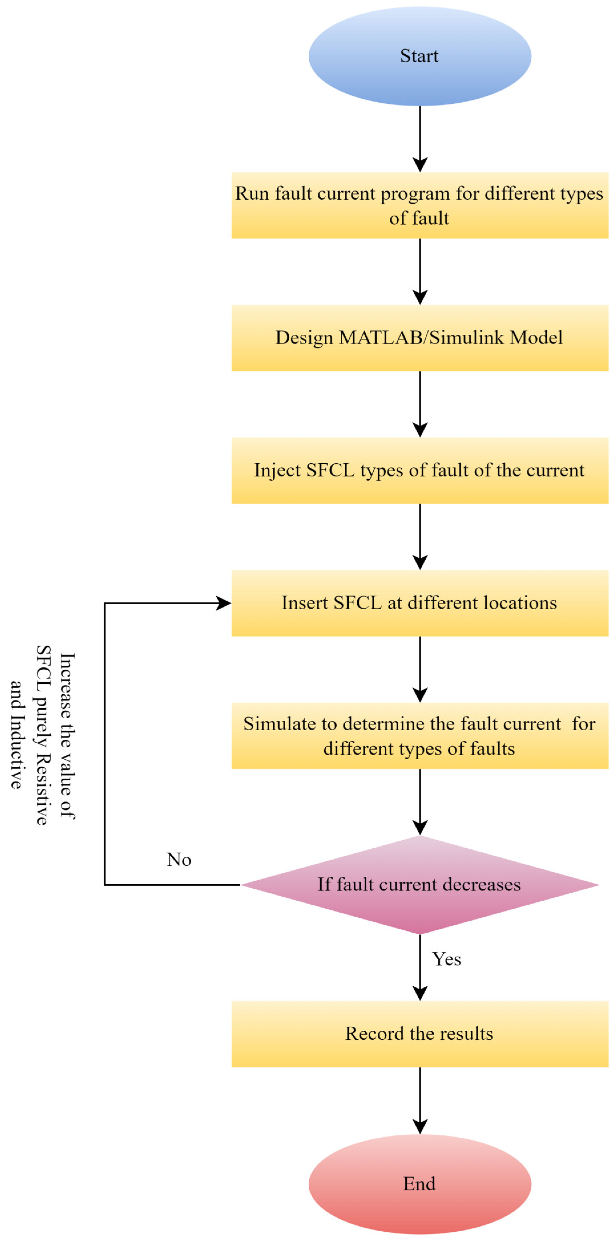
In
Figure 2, we see a flowchart illustrating the application of SFCL analysis to the problem of resolving unsymmetrical faults in a power system.
To further enhance line voltage stabilisation, closed-loop control methods may be implemented in DC-DC converters, and duty ratios may be adjusted in power switch circuits. The SFCLSMES combo strategy has the ability to rapidly reduce fault current and stabilise line voltage by making use of superconducting magnetic energy storage technology.
In
Figure 3, we can see the SFCL control loop, where E represents the disparity between y c and the actual output
where
y is the output of the system and
is the transfer function and
u is the updated value after calculating the error as:
Replacing Error
E is the equation, it becomes:
3.1. Modelling SFCL
During the negative and positive cycles, SFCL’s two iron cores are saturated with high DC current from a superconducting winding supply. Losses can be neglected if a direct current (DC) is employed in the superconducting winding. The normal and faulty alternating currents travel through two typical metal windings that are linked in series to the power line (one wound on each core). The following (
Figure 4) is a schematic diagram showing the electrical configuration at SFCL:
Since the DC current is so much higher than the AC current, the two iron cores are saturated in both directions under normal working conditions. This is why they have such low values of magnetic permeability and inductance. Each cycle’s midpoint is marked by an increase in alternating current (AC) to counteract the DC current, and the emergence of one iron core from the saturation zone.
Saturated-core SFCL can reduce fault current because it increases magnetic permeability and inductance.
In this research, we demonstrate the SFCL-based protection theory with an example failure event triggered by a control disturbance. According to Kirchoff’s law, the input voltage vin is equal to the average of the voltages across the SFCL, the inductor, and the on-state MOSFET
where the quench behaviour of superconductivity causes the
SFCL voltage
to follow a power-law distribution
where
is the superconductor’s critical electric field,
;
is the total tape used to wind the SFCL’s non-inductive coil; and
is the SFCL’s transitory over current. The critical current
Ic varies nonlinearly with
in real time
where nI and nT are two material-based indices that indicate the transient quenching process with respect to the operating current and temperature, and
Ic0 is a fitted constant equal to the ideal critical current of the superconductor at 0 K. Therefore, the SFCL’s equivalent resistance is denoted by:
When an on-state MOSFET experiences a malfunction, it is protected against thermal runaway if the junction temperature is kept below its maximum threshold Tmax
where
,
c, and Vvolume represent the initial temperature, heat capacity, material density, and thermal volume, respectively. Using characteristics of thermal diffusion, a suitable parameter of constant A is found. The integral of the instantaneous power during the failure can be used to calculate the heat created inside the on-state MOSFET.
3.2. Configuration of Reistive SFCL
There is a series connection between RSC1 and RSC2, and a parallel connection between RSC1 and CLR. This DC SFCL makes use of two superconducting elements to distribute the load more effectively. Superconducting components can save power with the help of a CLR. The RSC1 part cuts the voltage in half, even with a small fault current. In the event of a high fault current, the RSC1 and RSC2 elements work in sequence to sever the current in half. The two levels of triggering current are set once the DC SFCL has been designed.
3.3. Configuration of DC SFCL with Transformer
To facilitate switching between the two current levels and to give the power system more placement possibilities, a DC SFCL with transformer was developed.
To generate alternating current in an SFCL, a superconducting RSC2 element is wired to the secondary side of a transformer and supplied with power in proportion to the turn ratio of the transformer. Changing the transformer’s turn ratio in this DC SFCL affects the current at which quench occurs in RSC2.
If the CLR element can shoulder some of the load normally carried by the superconducting element, then the latter may be able to tolerate less power without sacrificing fault current efficiency. Alternating current (AC) systems can have a variety of different trigger current values, as shown in
Figure 5.
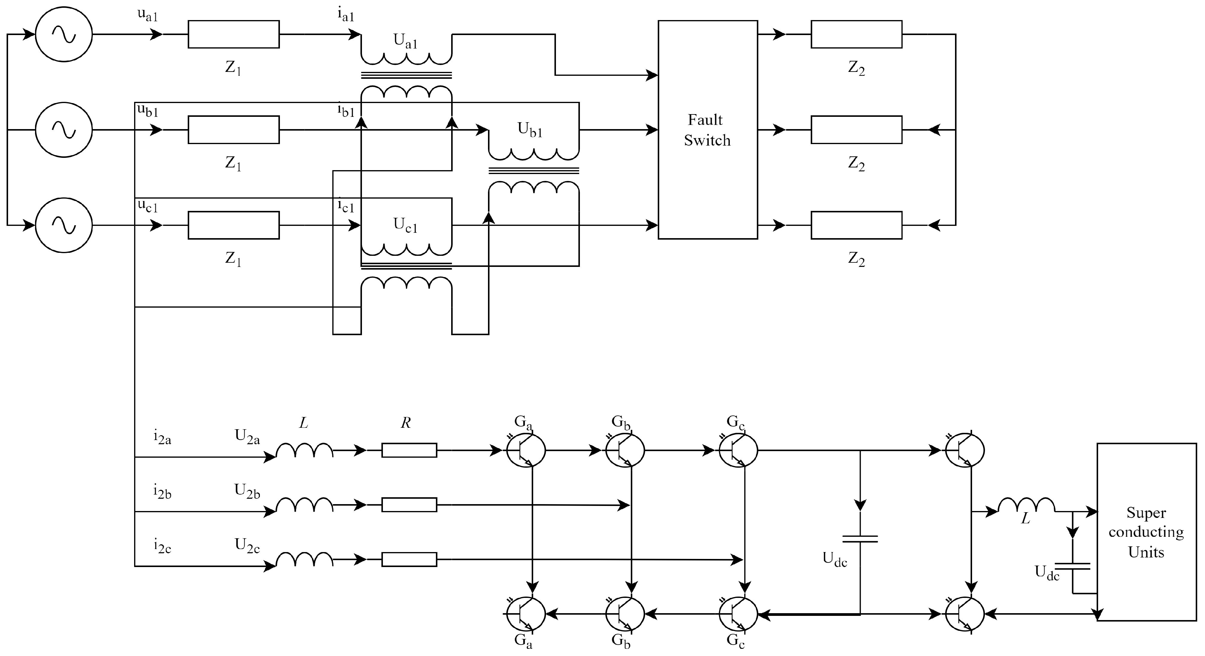
The use of a transformer in the construction of a DC SFCL is depicted in
Figure 6. In the CLR, the current through RSC2 is proportional to the turn ratio of the transformer (N1/N2), just as it is in the DC SFCL. If the fault current increases the normal-flowing RSC1 current above its critical value, the resistance of RSC1 will increase due to quenching. Since RSC1 is in charge of generating resistance, the DC SFCL can now use a transformer to regulate DC fault current. When current flows into Rsc1, it does so in two directions: along Rsc1 and the CLR, where it meets resistance. The turn ratio of a transformer determines how quickly current flows from the primary (N1) or CLR winding to the secondary (RSC2) winding. When the current in RSC2 exceeds its critical current, the same phenomenon occurs. When utilised to limit DC fault current, this transformer-based SFCL exhibits a quench in the RSC2 area. DC SFCLs can reduce DC fault currents by concurrently quenching RSC1 and RSC2, owing to their dual-triggering current levels.
3.4. Materials and Methods
The proposed DC SFCL has its fault current limiting capabilities tested using a transformer short circuit. As seen in
Figure 6, the DC SFCL with transformer is implemented in an experimental circuit.
Three phases of diodes in a bridge rectifier were used to change the alternating current (AC) ES voltage into direct current (DC) (VDC). When SS, the primary power supply switch, is closed, S1 and S2 will turn on.
Current flows exclusively through RLoad when connected in series with S1. S2 is closed and all power is going to RLoad and RFire. Assuming RLoad to be the real load, the DC short-circuit current can be determined by dividing the short-circuit current by this value. After S1 was connected to RLoad and closed at 0.1 s, S2 was set to close for 0.3 to 0.4 s to simulate the increased current from the short circuit. As a safety precaution, the master switch (represented by the letter SS) was flipped off.
The diagram shows a transformer with its primary winding connected in parallel to two superconducting components, RSC1 and RSC2. One of the CLR’s two terminals was wired in series with the primary winding of the transformer and the RSC1 superconducting element. The YBCO thin films were kept in a superconducting condition at 77 K by being stored in cryostats containing liquid nitrogen.
To avoid overheating, each superconducting component was connected to a shunt resistance. A shunt resistance of 2.3 was determined to be the bare minimum necessary when considering the typical superconducting element’s resistance of 80 to 100. Theoretically, the overall resistance will be reduced if the shunt resistor has a lower value than the superconducting component. The integration of a DC SFCL into a DC experimental circuit that makes use of a transformer is depicted in
Figure 7.
In the flux–flow zone (where
E (
t,
T) > E0 and
T (
t)
Tc), the superconductor temperature is found to be: (1). When
T (
t) >
Tc, the superconductor should be quenched. Equation (12) can also be written as,
E is the function of temperature
The duration of the fault is denoted by the time parameter T (t), which is expressed in seconds. The superconducting materials can be thought of as having two properties: temperature, denoted by Q, and conducting power, denoted by C. An inaccuracy E will occur if the incorrect current flow I is used. To measure the rate of heat transfer in a C superconductor, one can utilise the angular momentum change associated with an increase in temperature (denoted by Q in the thermodynamic notation).
Table 2 provides a concise overview of the key aspects of the experimental circuit, including the superconducting components. By adjusting the CLR’s resistance and inductance to three different values from
Table 2, we can examine the DC fault-current-limiting characteristics of this SFCL.
E (
T) is formulated as it is in Equation (16):
I and
Isc, as well as the non-temperature-dependent portion of
E (
T), may be merged in the following way [
17]:
For each error output E that is delivered, the absolute error of the updated output EO will decrease. Using an exponential model, time is represented by a coefficient.
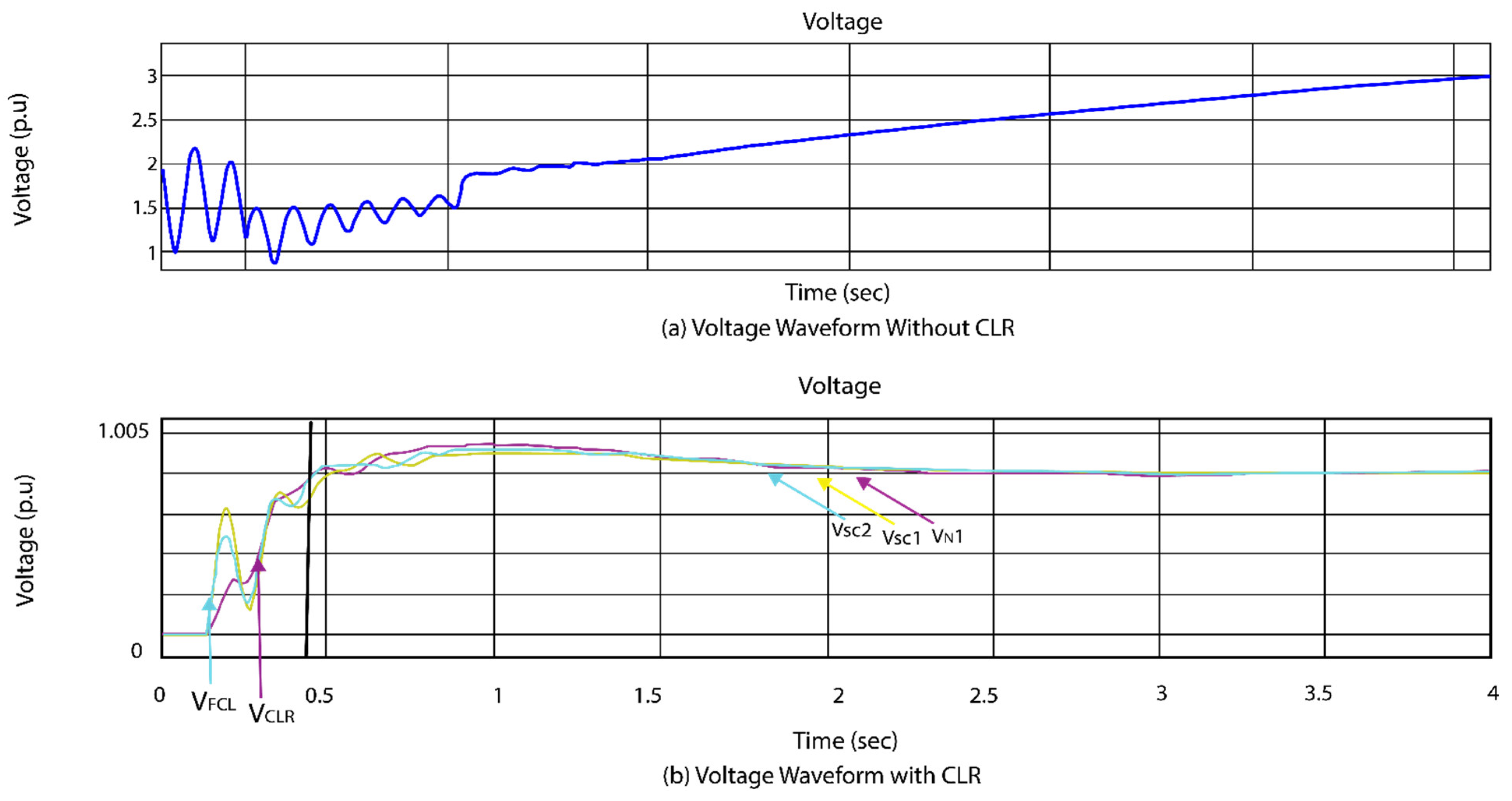
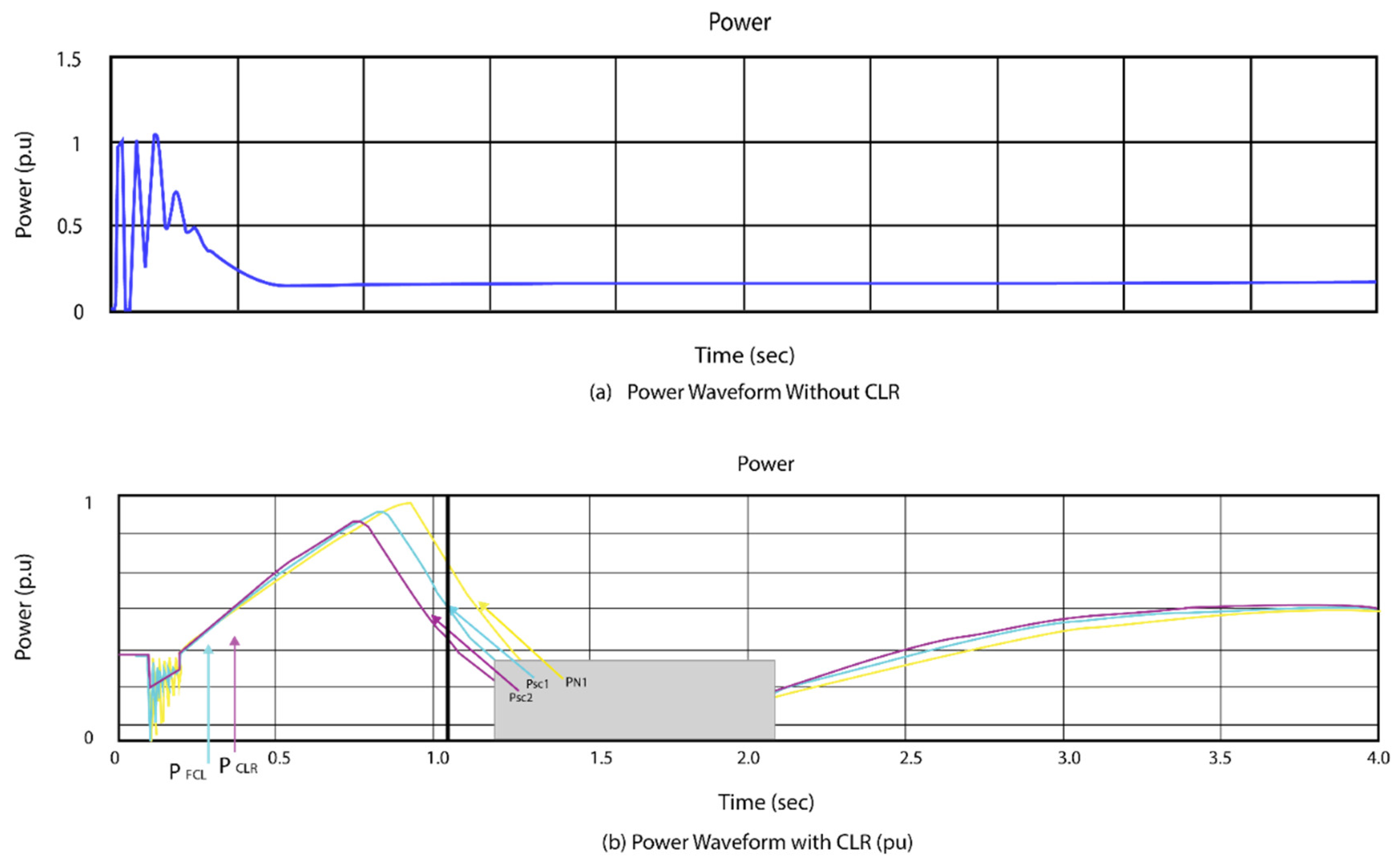
When the CLR component is a resistance, as shown in
Figure 8 and
Figure 9, the voltage and current waves look like (a) and (b). In under 0.3 s, SW2 was closed, causing a DC fault current to flow. Voltages were instantly generated in the primary winding and in both superconductors (VSC1 and VSC2) when DC faults occurred (VN1).
Figure 8 depicts the voltages of two superconducting components after an immediate overshoot of the critical current (IC) (ISC1, ISC2).


 ,
, 


