Multiple UAV Systems for Agricultural Applications: Control, Implementation, and Evaluation


1
Department of Rural and Biosystems Engineering, Chonnam National University, 77 Yongbong-ro, Buk-gu, Gwangju 61186, Korea
2
Hybrid Robotics Inc., 77 Yongbong-ro, Buk-gu, Gwangju 61186, Korea
*
Author to whom correspondence should be addressed.
Electronics 2018, 7(9), 162; https://0-doi-org.brum.beds.ac.uk/10.3390/electronics7090162
Submission received: 24 July 2018
/
Revised: 9 August 2018
/
Accepted: 22 August 2018
/
Published: 24 August 2018
(This article belongs to the Special Issue Autonomous Control of Unmanned Aerial Vehicles)
Abstract
:The introduction of multiple unmanned aerial vehicle (UAV) systems into agriculture causes an increase in work efficiency and a decrease in operator fatigue. However, systems that are commonly used in agriculture perform tasks using a single UAV with a centralized controller. In this study, we develop a multi-UAV system for agriculture using the distributed swarm control algorithm and evaluate the performance of the system. The performance of the proposed agricultural multi-UAV system is quantitatively evaluated and analyzed through four experimental cases: single UAV with autonomous control, multiple UAVs with autonomous control, single UAV with remote control, and multiple UAVs with remote control. Moreover, the performance of each system was analyzed through seven performance metrics: total time, setup time, flight time, battery consumption, inaccuracy of land, haptic control effort, and coverage ratio. Experimental results indicate that the performance of the multi-UAV system is significantly superior to the single-UAV system.
1. Introduction
Owing to the development of unmanned aerial vehicle (UAV) technology, there have been diverse studies on their applications in the agriculture field, which has the greatest potential for UAVs. According to the Association for Unmanned Vehicle Systems International (AUVSI), 80% of the commercial market for UAVs is expected to be occupied by agricultural UAVs in the future [1]. The reason why agricultural UAVs are popular is because they are expected to play an important role in overcoming some of the challenges of modern agriculture. In particular, an innovative agricultural UAV system is inevitable to ensuring the sustainability of agricultural productivity, which has become difficult to maintain because of climate change, and to meet the growing demand for agricultural products as the world’s population increases. Currently, agricultural UAVs are operated mainly for pest control and monitoring numerous crops such as soybean, corn, vegetables, and rice. However, agricultural UAVs are expected to be used for soil and field survey, sowing, spraying, monitoring, irrigation, growth evaluation, mapping, remote sensing, reconnaissance and transportation [2].
By introducing a UAV into traditional agriculture, working hours and labor requirements have been significantly reduced, and the efficiency of agricultural works has improved significantly [3]. However, because a UAV uses a limited battery as its main power source, it is more efficient to use a multi-UAV system, than the current system of a single UAV, to perform agricultural works [4,5,6]. For example, a single UAV is used for agricultural works such as spraying or monitoring a large farmland; however, it is very inefficient because it requires considerable time and energy. In contrast, when using a multi-UAV, it is possible to carry out cooperative works at the same time (collaboration) or individual agricultural tasks on the assigned farmland (division of labor). As a result, it is possible to complete the agricultural tasks quickly on a large farmland. In others, when using multiple UAVs to find diseased crops, the accuracy of the agricultural tasks is also being increased or equal because there are overlapping areas between the mission areas of each UAV. Although the accuracy of the agriculture task may be superior for a single UAV with a well-planned path, it is greatly influenced by the path planning algorithm. Therefore, the multi-UAV system is more efficient in many ways than the single-UAV system currently in use.
However, when analyzing the existing application of UAV system for agriculture (see, for instance, [7,8,9,10,11,12,13,14,15,16,17,18,19,20,21,22]), most studies execute agricultural tasks using a single UAV with an autonomous control. There are few studies on the use of the multi-UAV system in performing agricultural works; thus, it is only at the advanced stage of research [19,21,23]. In [19], an autonomous system for use in inspections for precision agriculture based on the use of single and multiple UAVs was developed. In addition, in [21], precision agricultural technology based on the deployment of a team of UAVs that are able to take georeferenced pictures in order to create a full map by applying mosaicking procedures for post-processing was studied. Although [19,21] used the multi-UAV system for agricultural tasks, they used the centralized controllers through commercial software or a number of computers and did not perform a quantitative evaluation as the number of UAVs increased; thus, they overlooked the ease of the swarm controllers used.
Even if a multi-UAV system is used in agriculture, the most important factor is that the ease of control must be met such that a single operator can easily control multiple UAVs similar to controlling a single-UAV system. In our previous study [24], we developed a distributed swarm control algorithm and implemented a multi-UAV system into the simulator such that a single operator can easily control the multiple agricultural UAVs. Additionally, we argued that the agricultural task with a swarm control algorithm that efficiently and safely controls the multiple UAVs allows the operator to control the multiple UAVs more easily and intuitively and maximize the efficiency of agricultural works. To achieve this, this paper extends the previous study [24,25] by quantitatively evaluating the performance of multi-UAV systems with the proposed algorithm in agricultural scenarios.
For the agricultural scenarios, the remote sensing that represents the task of the agricultural UAV has been set as a benchmark test in this study, and the reason why remote sensing is a representative task is explained in detail in Section 2. In the evaluation, we focused on the ease with which the operator can control the multiple UAVs and improve the efficiency of agricultural works when performing remote sensing tasks using the developed agricultural multi-UAV system. Therefore, the experimental cases are divided into the use of a single-UAV system and the use of a multi-UAV system from the viewpoint of the number of UAVs. Furthermore, we compare the experimental cases by applying an automatic control method and remote-control method from the viewpoint of control. In other words, we perform a total of four experimental cases (single-UAV system using automatic control, hereafter, referred to as Auto-Single-UAV; multi-UAV system using automatic control, hereafter, referred to as Auto-Multi-UAV; single-UAV system using remote control, hereafter, referred to as Tele-Single-UAV; and multi-UAV system using remote control, hereafter, referred as to Tele-Multi-UAV) for remote sensing tasks. Finally, a total of seven performance metrics (total time, setup time, flight time, battery consumption, inaccuracy of land, haptic control effort, coverage ratio) were defined to describe and predict the performance of an agricultural UAV system.
2. Review about the Application of UAV in Agriculture
In order to apply the multi-UAV system with distributed swarm control algorithm for agriculture, it is necessary to confirm the type of agricultural UAV to be used and the type of agricultural task to be carried out. Therefore, in this section, the studies that utilized the existing agricultural UAV system are investigated and analyzed in Table 1.
Table 1 reveals an increasing interest in UAVs in the field of agriculture in recent years, and most agricultural UAVs currently in use are single-UAV systems except for [19,21]. The main research areas are remote sensing [7,8,10,13,17,18,20,22], mapping [7,8,11,15], and monitoring [9,12,14,19,26], and it is not yet used in various areas such as sowing and harvesting. Furthermore, the research for irrigation and pest control is on the rise nowadays [16,27,28]. In particular, the remote sensing task is the most widely used task of research for agricultural UAVs and is a basic task achieved by attaching additional hardware or controllers at any time. For this remote sensing, A. Barrientos et al. developed a path planning algorithm and performed the area coverage task [21]. As a result, in this study, the remote sensing task was set as a benchmark test because it is the basis for all agricultural tasks.
In sensors, RGB cameras [13,14,15,19], thermal cameras [7,8], and multi-spectral cameras [7,8,9,10,11,12,17,18,20,22] are used. Recent studies focused on agricultural UAVs through image processing, including preprocessing, onboard-processing and post-processing; thus, it is widely used in camera sensors. In addition, a spraying system was installed in the UAV for control, or a related sensor and controller was used in [13,16]. In particular, almost all UAVs are equipped with inertial measurement unit (IMU), pressure sensor and global positioning system (GPS) in common, and it is expected that agricultural UAVs for fully autonomous navigation using IMU and image processing will be developed in the future.
Recently, agricultural UAVs are mainly multi-copter type UAVs, and the fixed-wing type [7,18] or helicopter type [16,20] UAV that was used in the past is gradually disappearing. The reason for the increase in multi-copter type UAV is that the structure is simple, the noise and vibration are small, and it is easy to move and store by folding the frame. It also has the advantage of not requiring a large space for takeoff and landing; however, it also has a problem of low payload and flight time. One of the ways to solve this problem is to use multiple UAVs [29,30].
However, most agricultural UAV systems do not have a multi-UAV system and are still being developed to address the limitations of a single-UAV system [31]. In the case of research using multi-UAV, the completion time of the mission is remarkably shortened, and the efficiency of the work is greatly improved [21]. Taking this advantage into consideration, the agricultural multi-UAV system is essential for automation and unmanned technology of future agriculture, and it is considered as one way to solve the food shortage problem. In the case of Swarm Robotics for Agricultural Applications (SAGA) projects in Europe, for more details, see [32], agricultural swarm robotics is studying to prepare for the fourth industrial revolution and to build precision agriculture and smart farm [33]. Another project, Mobile Agricultural Robot Swarms (MARS), aimed to develop small and stream-lined mobile agricultural robot units to fuel a paradigm shift in farming practices. Recent research trends are focusing considerable attention on multi-robots and swarm robotics; furthermore, multiple agricultural UAVs are expected to become the core of future agricultural technology.
Therefore, the proposed agricultural multi-UAV system based on the distributed swarm control algorithm is a necessary study for the future agricultural technology, and quantitative evaluation of developed system contributes to the performance evaluation of the agricultural UAV system which has not been examined previously.
3. The Control of Multiple UAV System
3.1. UAV Dynamics
We consider N quadrotor-type UAVs with 3-DOF Cartesian positions that are denoted by , . Flight control of UAVs is derived from the following under-actuated Lagrangian dynamics equation in [34]
with the following attitude kinematic equation
where denotes mass, denotes the Cartesian center-of-mass position represented in the north-east-down (NED) inertial frame , denotes thrust control input, denotes the rotational matrix describing the body frame of UAV w.r.t. to the inertial frame , g is the gravitation constant, denotes the basis vector representing the down direction and representing that thrust and gravity act in the D direction, denotes the UAV’s inertia matrix with respect to the body frame , denotes the angular velocity of the UAV relative to the inertial frame represented in the body frame , denotes the attitude torque control input, denote the aerodynamic perturbations, and denotes the skew-symmetric operator defined such that for . For typical UAV flying, .
3.2. Distributed Swarm Control
In the previous study [24], we developed the following distributed swarm control on each UAV, for the ith UAV,
where the meaning of the three control inputs and represents the velocity terms of the UAV.
3.2.1. UAV Control
The first velocity term, denotes a control input that directly controls the UAV and represents a velocity control input according to the control method. Normally, the UAV control method mainly uses the following three methods: the method of fully autonomous driving (); the method of driving on a certain path specified by the operator (); the method of teleoperation by the operator in real time (). In the case of , the position of the UAV at time t, given the previous k positions and the corresponding laser measurements , is as follows:
where . We briefly review the control of autonomous UAVs and refer the reader to [35] for further details. In this study, because there are many limitations to apply to farming in the case of , was set as an automatic control method and was set as a remote control method. Additionally, and are discussed in detail in Section 3.3 and Section 3.4.
3.2.2. Formation Control
The second velocity term, denotes a control input to avoid a collision among UAVs, preserves connectivity, and achieves a certain desired formation as specified by the desired distances , as defined by
where denotes a certain artificial potential function to create an attractive action if , a repulsive action if , and a null action if .
3.2.3. Obstacle Avoidance Control
The final velocity term, , is expressed by the following equation as a control input based on a potential field that allows multiple UAVs to avoid obstacles through a certain distance threshold:
where denotes the set of obstacles of the ith UAV with an obstacle point that corresponds to the position of the rth obstacle in the environment, and denotes a certain artificial potential function that produces a repulsive action if , and a null action if . When the distance between the UAVs and the obstacles becomes closer to , then the repulsive potential function increases to infinity.
Here, we briefly reviewed the distributed swarm control architecture and refer the reader to [24] for further details.
3.3. Autonomous Control
Automatic control of UAV through a ground station uses the navigation control based on GPS waypoint. The navigation control uses PID controller when UAV is in GUIDED mode, as defined by
where denotes the target position, denotes the position error between target point and UAV, and and are the gain values of the navigation controller, respectively.
In (8), the UAV follows the target point preset by the operator, and the position error decreases gradually. Here, the velocity of the UAV changes according to the position error. However, because the performance of the navigation controller changes depending on the gain value, appropriate values must be set through tuning.
3.4. Teleoperation
The teleoepration uses the haptic device to control the UAV. Therefore, we consider a 3-DOF haptic device for master as modeled by the following nonlinear Lagrangian dynamics equation [36]
where denotes the configuration of the haptic device (e.g., the position of end effector), denotes the positive-definite/symmetric inertia matrix, denotes the Coriolis matrix, and , denote the control input and human forces, respectively.
The velocity term, , represents the teleoperation command for the desired velocity input of the UAV that is directly controlled by the operator by using the configuration of the haptic device q
where denotes a constant scale factor used to match different scales between q and the UAV desired velocity , and denotes the position of end effector. In (10), multiple UAVs with an unbounded workspace can fly without the limitations of workspace by controlling the desired velocity by using the configuration of the haptic device with a bounded workspace.
4. Experimental Design
4.1. Remote Sensing Task
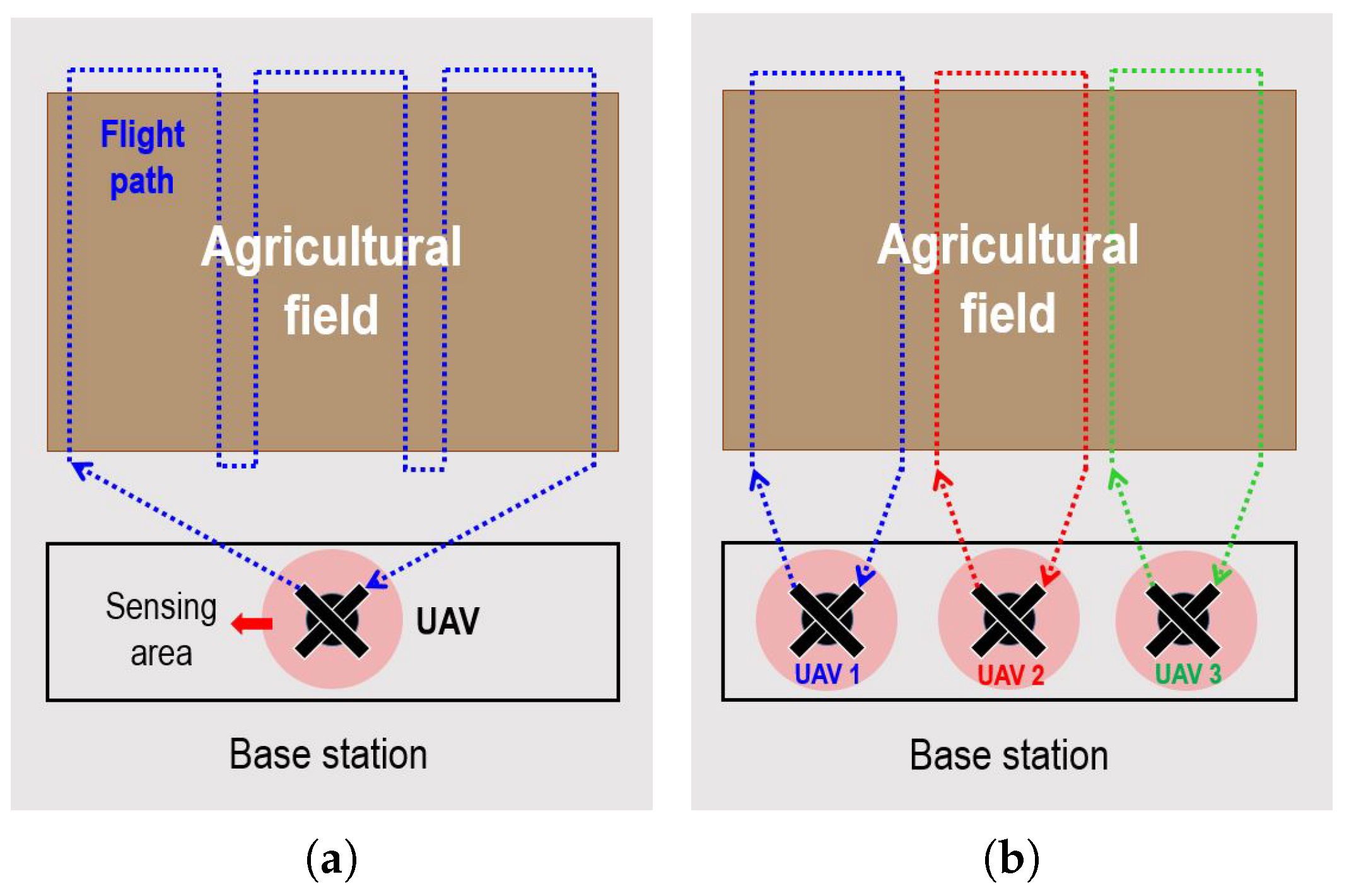
In this experiment, we set the remote sensing for the agricultural task as shown in Figure 1, and the reason for setting this task is explained in Section 2. The experiment is the operation of sensing using UAV with mounted sensors for a predetermined test area, and the experimental procedure includes the whole process from setup time before takeoff to landing after a flight time of mission. The starting point of the remote sensing task is the position where the UAV was originally located at the base station, and this point is also set as the ending point.
Experimental progress is required for the operator to control the agricultural UAV system based on the distributed swarm control algorithm while performing the remote sensing through the sensor attached to the UAV. In addition, the operator was required to look at the formation of the UAV from the remote site or to control it by looking at the camera screen mounted on the UAV. At this time, there is no reference path for the remote sensing tasks, and the UAV is remotely controlled by the intuitive judgment of the operator or is automatically controlled by setting a suitable waypoint. The time at which the UAV was landing properly was set as the criterion for the end of the experiment and the success of the experiment. Here, the operator decided to terminate the experiment by judging the moment when the UAV landed successfully.
Experiments consisted of four cases consisting of Auto-Single-UAV, Auto-Multi-UAV, Tele-Single-UAV and Tele-Multi-UAV. In the case of multi-UAV cases, a total of three quadcopters was used for remote sensing. When automatic control is used, the UAV is automatically controlled by specifying the GPS-based waypoint using ground control station (GCS). However, in the case of teleoperation, the operator controls the UAV by controlling the haptic device. In other words, the experimental cases are defined by
- Auto-Single-UAV: ,
- Auto-Multi-UAV: , where the target position
- Tele-Single-UAV: ,
- Tele-Multi-UAV: ,
In the case of Tele-Multi-UAV, it is a multi-UAV system applying our proposed distributed swarm control algorithm. A total of three trials were performed for each case and a total of 12 trials were performed in agricultural experiments.
4.2. Performance Metric
We used a total of seven performance metrics to evaluate the performance of agricultural UAV systems. The performance metrics are mainly focused on the control effort of the operator and the performance of the system for the agricultural task, and total time, setup time, flight time, battery consumption, inaccuracy of land, haptic control effort, and coverage ratio were used as the metrics.
Definition 1.
Total timeis the completion time during the agricultural task as defined by
where is the start time, is the completion time of the agricultural task.
Definition 2.
Setup timeis defined as the time that the operator prepares before the UAV executes the agricultural task,
where is the time that UAV takes off to perform the agricultural task.
Definition 3.
The metric for theFlight timeis
Definition 4.
Battery consumptionis defined as
where is the total amount of batter and is the consumption of the battery.
Definition 5.
The metric for theInaccuracy of landis
Definition 6.
Haptic control effortis defined as the total distance of haptic device moved by operator shown in below,
where is the configuration of the haptic device.
Definition 7.
Coverage ratiois defined as
where is the area covered by the sensor mounted on UAV, and is the area covered by sensor per time.
, , and are basically the most important time factors for the UAV to perform agricultural tasks. As the value of these metrics increases, it implies that energy and costs for agricultural task increase. Therefore, the smaller the value of , , and , the better the performance of the system. Similarly, the lower the value of , and , the lower the energy consumption of the UAV, the lower the error of the landing, and the lower the control effort of the operator. However, the values of indicate the performance of the remote sensing tasks; therefore, the higher the value, the better the performance.
4.3. Experimental Setup
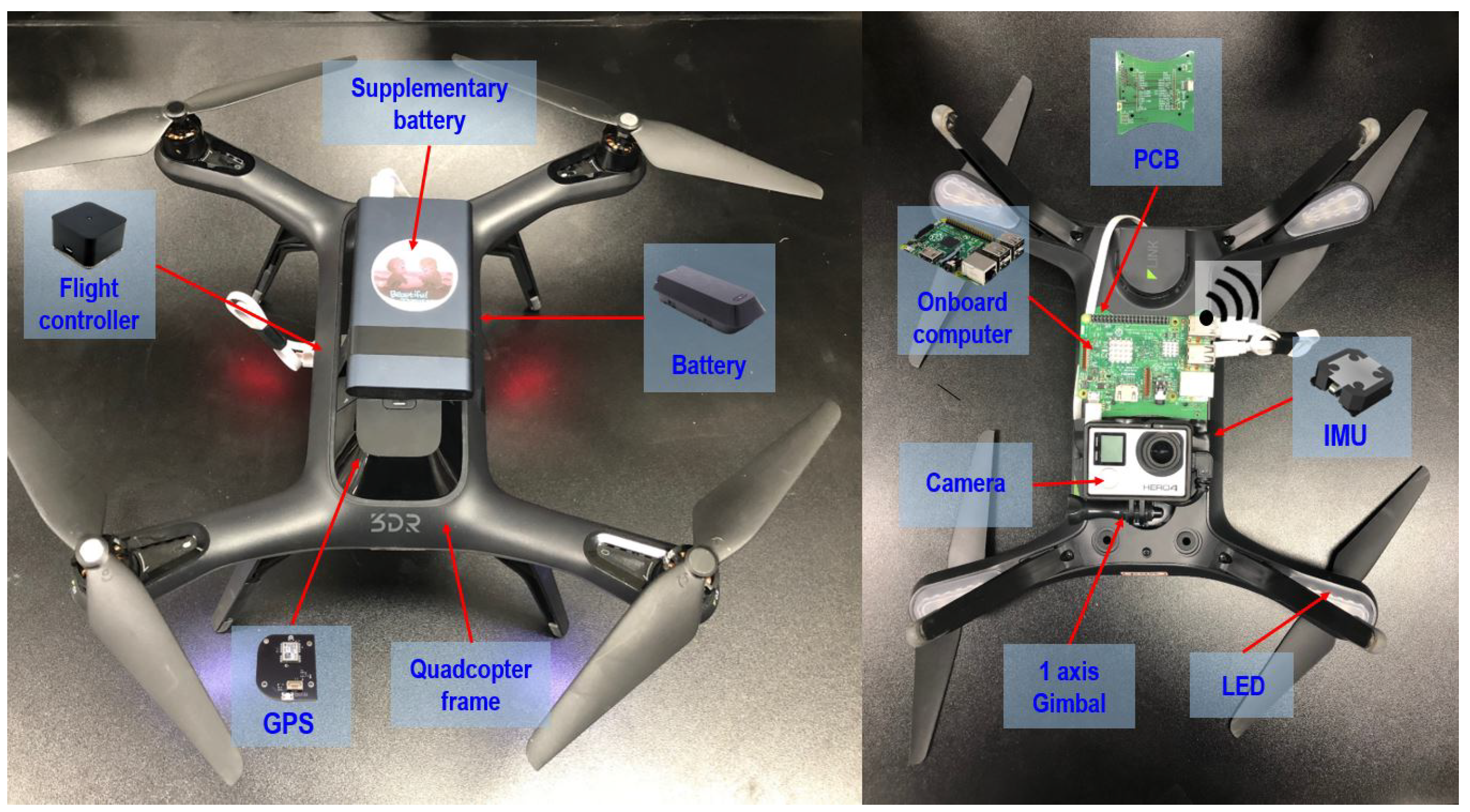
The experimental environment was built to allow the UAV to control and communicate with ROS on the notebook of the 16.04 LTS version Ubuntu. In the experiment, a remote sensing task is performed while recording a real-time image by attaching an RGB camera to the UAV. The experimental environment is shown in Figure 2 and the experiment was carried out on a clear day with low geomagnetic coefficient. The UAV used in the developed system was a quadcopter type UAV (3DR SOLO), which is suitable for remote sensing because of low vibrations. As shown in Figure 3, the UAV is basically composed of a frame and battery, a GPS receiver and a flight controller (FC), a camera, an IMU consisting of an accelerometer, a gyroscope, and a magnetic field, supplementary battery that supplies power to the onboard computer, onboard computer for controller, and a printed circuit board (PCB) for connection between the UAV and onboard computer. The payload of this UAV is 450 g, and it flies without problems when all the components are connected; in this state, it can fly up to 20 min.
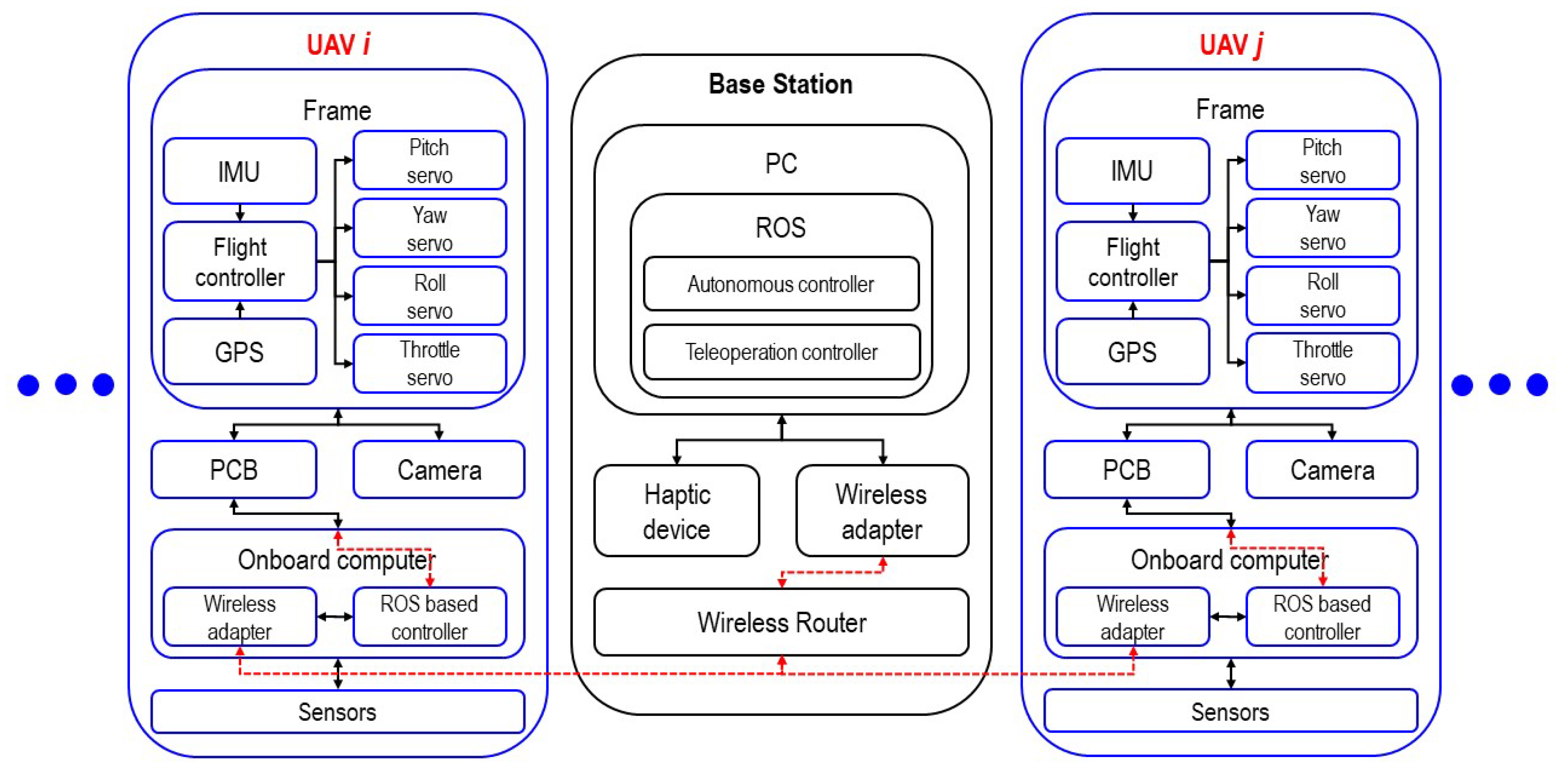
For the distributed system, we constructed a multi-UAV system using the above UAV, and the developed system consists of a number of UAVs and a base station. As shown in Figure 4, the base station consists of a PC with a ROS-based controller and a haptic device, which is used as the master device for teleoperation, a wireless adapter, and a router for the user datagram protocol (UDP) communication. Here, each PC and the onboard computer mounted on the UAV communicate with each other through a router and exchange data, thereby constructing a distributed system. It is also possible to construct a centralized system easily using this system configuration.
Communication basically used UDP communication and changed the default port of each UAV to avoid interference between UAVs. After changing the default port of the UAV, we set up the onboard computer to automatically connect to the router’s network used in this experiment. Therefore, when the UAV is booted, it is automatically located on the same network with a computer without any configuration and recognizes and communicates with each other through different IP address and ports. The channel used 2.4 GHz frequency, and the optimum channel was set to receive the data out of interference.
4.4. Data Acquisition and Analysis
During the experiment, we recorded the local position, global position, linear velocity, angular velocity, battery state, and heading value of the UAV, as well as the experiment time, position and force of the haptic device, and the raw date of sensors at 1000 Hz in the ground station. All data were transferred from UAV to the ground station through Micro Air Vehicle Communication Protocol (MAVLink), and we monitored the data via rostopic, which is command-line tool for displaying debug information about ROS topics, including publishers, subscribers, publishing rate, and ROS Messages, and stored it using rosbag, which is a set of tools for recording from and playing back to ROS topics.
5. Experimental Results
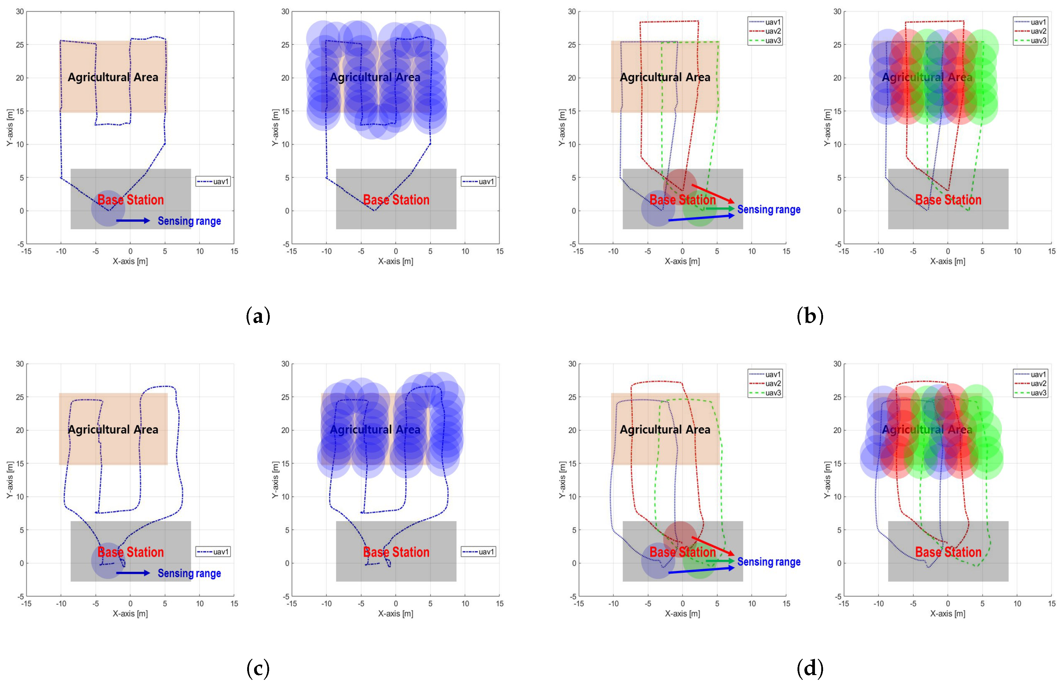
Figure 5 shows the results of one flight trial. We performed a statistical analysis of performance metrics after all experiments (3 trials per case, 12 trials in total), which are summarized in Table 2.
5.1. Total Time
Because is the sum of and , a detailed evaluation should identify two metrics. However, is one of the most important factors when evaluating the system, because it shows intuitively the completion time of the remote sensing task. In addition, a smaller reduces the overall energy consumption and saves the cost of operating the system. is the highest for Auto-Single-UAV and lowest for Tele-Multi-UAV in experiment results. Additionally, is less in the teleoperation method than in the automatic control method, and the multi-UAV system is less than the single-UAV system. In detail, decreased by 31.1 s from 96.2 s (Auto-Single-UAV) to 65.1 s (Tele-Single-UAV) and decreased by 46.2 s from 78.8 s (Auto-Multi-UAV) to 32.6 s (Tele-Multi-UAV).
When using the multi-UAV system, the decrease was 17.4 s from 96.2 s (Auto-Single-UAV) to 78.8 s (Auto-Multi-UAV) and 32.5 s from 65.1 s (Tele-Single-UAV) to 32.6 s (Tele-Multi-UAV). Moreover, when comparing the proposed Tele-Multi-UAV and Auto-Single-UAV, experimental results show that for Tele-Multi-UAV is approximately 66.1% (from 96.2 s to 32.6 s) lower than Auto-Single-UAV.
5.2. Setup Time
is what an operator does before the UAV performs an agricultural task, which is related to the operator’s control effort aspect. No matter how good a system is, it is not good if the control effort of the operator is significant. Therefore, is a very important metric and should be considered when developing a system. In experiments, is the highest at 64.5 s (Auto-Multi-UAV) and is the lowest at 13.5 s (Tele-Single-UAV). The tendency is that is less when using teleoperation method compared to automatic control method; however, when the multi-UAV system is used, increases more than the single-UAV system. Quantitatively, decreased by 35.2 s from 48.7 s (Auto-Single-UAV) to 13.5 s (Tele-Single-UAV) and decreased by 45.6 s from 64.5 s (Auto-Multi-UAV) to 18.9 s (Tele-Multi-UAV). However, increased from 48.7 s (Auto-Single-UAV) to 64.5 s (Auto-Multi-UAV) in 15.8 s and from 13.5 s (Tele-Single-UAV) to 18.9 s (Tele-Multi-UAV) in 5.4 s.
Most importantly, of Tele-Multi-UAV compared to Auto-Single-UAV was reduced by 61.2% (from 48.7 s to 18.9 s). Additionally, of Tele-Multi-UAV compared to Tele-Single-UAV was increased by 39.9% (from 13.5 s to 18.9 s). for Auto-Multi-UAV increased by 32.4% (from 48.7 s to 64.5 s) compared to Auto-Single-UAV. This result means that the use of multiple UAVs unconditionally increases the work efficiency; however, the operator’s control effort and fatigue increased even more. However, this result is heavily influenced by the user interface (UI), controller and feedback [37,38].
5.3. Flight Time
is the time that UAV travels for agricultural task and is directly related to the energy consumption of UAV. In other words, is the working time of UAV, and the smaller the , the shorter the working time and the less energy consumption. However, it can vary greatly depending on the gain value of the velocity control input. The experimental results show that is the lowest for Tele-Multi-UAV (13.7 s) and the highest for Tele-Single-UAV (51.6 s). However, there is no significant difference between Tele-Multi-UAV (13.7 s) and Auto-Multi-UAV (14.3 s). Considering Auto-Single-UAV (47.5 s) and Tele-Single-UAV (51.6 s), increase when the teleoperation is used rather than automatic control.
It is seen that is significantly reduced when using multiple UAVs rather than a single-UAV system. In the case of Auto-Single-UAV and Auto-Multi-UAV, the decrease was 33.2 s (from 47.5 s to 14.3 s). Additionally, in the case of Tele-Single-UAV and Tele-Multi-UAV, the decrease was 37.9 s (from 51.6 s to 13.7 s). Obviously, the case of Tele-Multi-UAV had a 71.2% (from 47.5 s to 13.7 s) decrease in compared to Auto-Single-UAV in the experiment. These results indicate that using a multi-UAV system can save the battery by reducing over a single-UAV system.
5.4. Battery Consumption
The UAV typically consumes considerable battery power when flying; is similar to the . This metric is very important as an intuitive indicator of the potential for solving the battery shortage problems facing current agricultural UAVs. Therefore, the smaller the , the better the performance of the agricultural UAV system.
In experiments, is the smallest at 1.2% for Tele-Multi-UAV and the largest at 4.2% for Tele-Single-UAV. The difference between Tele-Multi-UAV and Tele-Single-UAV is 3.0%; however, if is longer, the difference in increases even more. Additionally, decreased by 2.3% from 3.9% (Auto-Single-UAV) to 1.6% (Auto-Multi-UAV) when using the multi-UAV system. Furthermore, in the case of Tele-Multi-UAV, the results show that is 2.6% (from 1.2% to 3.9%) less than Auto-Single-UAV. As a result, it is more efficient to use multiple UAVs than to use a single UAV, because when nth UAV performs the agricultural task, the agricultural area is divided by n, and each UAV performs an agricultural task only on areas. However, if we proceed to the same accuracy of agricultural task for a given farmland, the teleoperation method consumes much more than the automatic control method. This is because the control is limited when the operator performs teleoperation on the remote site.
5.5. Inaccuracy of Land
is not an index related to the performance of agricultural task; however, it is an element that affects the performance of the system. This metric is set to determine the accuracy of landing and is a very important performance metric when the base station is a narrow or dangerous area or when the UAV lands on the unmanned ground vehicle (UGV). Therefore, this metric must be considered to build smart farming in the future.
is the highest for Auto-Multi-UAV (19.3 cm) and lowest for Tele-Single-UAV (8.3 cm) in experiment results. The reason for this is that the disturbance can not be ignored when performing the experiment in an outdoor environment, and error is particularly affected by GPS, which is considered to be inaccurate because of the performance of the device or the weather and wind. Generally, tends to increase when using multiple UAVs. In detail, increased 1.3 cm from 18.0 cm (Auto-Single-UAV) to 19.3 cm (Auto-Multi-UAV) and increased 5.5 cm from 8.3 cm (Tele-Single-UAV) to 13.8 cm (Tele-Multi-UAV). The reason why increases when using multi-UAV is because signal disturbance occurs. Additionally, decreased by 23.3% (4.2 cm) from 18.0 cm (Auto-Single-UAV) to 13.8 cm (Tele-Multi-UAV). However, this result is reversed when using a more accurate and expensive GPS receiver.
5.6. Haptic Control Effort
numerically shows the control input of the operator when using the teleoperation. In order to more precisely measure the control effort of the operator, it is necessary to measure the input force; however, in this study, is regarded as a general control effort (e.g., see [39]). Experimental results show that is significantly reduced when using a multi-UAV system than when using a single-UAV system. Quantitatively, decreased by 15.8 cm from 31.1 cm at Tele-Single-UAV to 15.3 cm at Tele-Multi-UAV.
As a percentage, the control effort at Tele-Multi-UAV tended to decrease by 50.9% (from 31.1 cm to 15.3 cm) in the experiment compared to Tele-Single-UAV. The reason for this is that when using a single-UAV system, basically it is necessary to carry out multiple flying and agricultural tasks, and therefore, the effort of the operator to control the haptic device is inevitable. These results indicate that using the multi-UAV system rather than a single-UAV system, as opposed to , reduced the operator’s control effort. can be regarded as a limitation of teleoperation rather than automatic control; however, if the proper haptic feedback adds to the operator, the UAV can be controlled almost without operator’s control input, similar to automatic control [40].
5.7. Coverage Ratio
yields the performance of the agricultural task by calculating the covered area at the same time. This metric should be considered when developing a system as a very important indicator along with in performing agricultural works. No matter how fast is, if is low, the efficiency of the agricultural task will be low. Therefore, represents the simultaneous covered area of the agricultural UAV system. In the experiment, the recording was done for the test area through the RGB-camera mounted on UAV. As a result, of a single-UAV system is only one-third of the performance compared to a multi-UAV system. In particular, when multi-UAV system is used, is increased by as many as the number of UAVs; thus, it offers a much better performance.
6. Discussions
Table 3 summarizes the experimental results on the comparison between single and multiple systems and the comparison between automatic control and teleoperation. The results show the increase and decrease in teleoperation based on the single-UAV system when Single → Multi and automatic control when Auto → Tele.
6.1. Single vs. Multiple
Currently, a method for solving the problems of battery and payload shortage in an agricultural UAV system is to use a multi-UAV system. Using multiple UAVs requires more time to set up and extra initial cost; however, it brings about results such as improved accuracy of agricultural task, reduced working time, and reduced operator’s control efforts. As a result, agricultural multi-UAV systems are regarded as better systems than single-UAV systems. However, it is necessary to thoroughly confirm that it has acceptable performance before introducing the agricultural multi-UAV system. Therefore, in this subsection we will quantitatively evaluate and analyze the single-UAV system and multi-UAV system.
First, if Multi-UAV is used, is reduced by 18.1% at Auto-UAV and reduced by 50.0% at Tele-UAV. These results show a clear reduction in for Multi-UAV, which improves the efficiency of agricultural works. Although three UAVs were used in this study, the agricultural multi-UAV system based on distributed swarm control showed better performance as the number of UAVs increased and the farmland became larger. However, experimental results show that increases with Multi-UAV. An 32.4% and a 39.9% increase in Auto-UAV and Tele-UAV were confirmed, respectively. These values are disadvantages of the multi-UAV system; however, it is a more efficient system because multiple UAVs are controlled with a few . Generally, to control three UAVs, a of three times is required. However, if the operator controls the multi-UAV with additional of only 30.0%∼40.0%, the agricultural works are economically beneficial. First, is greatly influenced by UI; thus, is significantly reduced if human-centered GUI and PUI are developed.
Even though increases, multiple UAVs reduce of each UAV through collaboration. This is the main reason why decreases even if increases. In the experimental results, Auto-UAV and Tele-UAV decreased by 69.8% and 73.5%, respectively. Because three UAVs are used for Multi-UAV, theoretically it should be reduced by approximately 66.0%. However, in the experiment, it is confirmed that it is lower than the reference value (66.0%), which means that the energy of the UAV is further reduced. Furthermore, because decreases, is reduced, and the experimental results show that is reduced by 59.3% (Auto-UAV)∼70.5% (Tele-UAV) when three UAVs are used. As a result, it is considered that the multi-UAV system overcomes the battery shortage problem of current agricultural UAV systems. Therefore, no matter how vast the area of farmland is, multiple UAVs collaborate to perform agricultural tasks without encountering battery shortage.
Even though tends to increase when using Multi-UAV, this metric is subject to a change by other factors. For example, in the case of Auto-UAV, is greatly influenced by GPS. However, GPS varies with device resolution, wind, weather, and geomagnetic factors. In the case of Tele-UAV, can be greatly influenced by UI because the operator directly watches the UAV or the camera mounted on the UAV for takeoff and landing. Interestingly, experiments show that decreases when using multiple UAVs. This metric is only for Tele-UAV, which decreased by 50.9% in the experiment. These results are related to , because the area allocated to each UAV is reduced; thus, it is natural that is reduced. Unlike , decreases as UAV increases; thus, it is advantageous to use agricultural multi-UAV systems based on the distributed swarm control.
Finally, is significantly improved. When multiple UAVs are used, increases (200.0%); thus, accuracy of remote sensing also increases, which lead to an increase in the efficiency of the farming. clearly shows that the accuracy of the agricultural works when using Multi-UAV is improved.
As a result, when using the multi UAV system, a little is required because it offers improved results in almost metrics (. In other words, Multi-UAV reduces the time, cost and operator’s environment, including the control effort in agricultural works. In addition, the battery shortage problem and low payload are easily solved, which are the current challenges of agricultural UAVs.
6.2. Autonomous vs. Teleoperation
The use of automatic control when controlling an agricultural UAV saves much control effort on the operator side. However, there are many limitations to applying the automatic control to actual farming, and there are moments when the teleoperation command of the operator is needed. Additionally, when teleoperation is used, it offers a better performance in working duration than automatic control. Each control method has advantages and disadvantages, and it is necessary to quantitatively evaluate the performance of the system.
decreased by 32.3% (Single-UAV) and 58.7% (Multi-UAV) when Tele-UAV was used. Additionally, experimental results show that Tele-UAV has excellent performance in terms of . In particular, is reduced by 72.2% (Single-UAV) to 70.7% (Multi-UAV) compared to Auto-UAV, and the simulation is also reduced by 81.3% (Single-UAV) to 82.1% (Multi-UAV). These results mean that there is nothing to set in the case of Tele-UAV; however, in the case of Auto-UAV, a long is required because it is necessary to specify the path to each UAV. Unusually, increased for Single-UAV but decreased for Multi-UAV in the experiment results. However, the teleoperation method basically requires more . The reason for this result in the experiment was that when using Tele-Multi-UAV, the operator did not control the UAV carefully and this carelessness caused the low accuracy of the agricultural task by flying fast. However, Auto-UAV running on GPS based waypoints is accurate and faster.
For other metrics, is similar to as mentioned above. In , the results shows excellent performance when using Tele-UAV than using Auto-UAV. These results are due to the fact that GPS is interfered with the outdoor environment and is very variable. It means that performance is worse, and the UAV is dangerous when using Auto-UAV where GPS is not accurate. Particularly, it is a great advantage of Auto-UAV that the operator does not need . However, Auto-UAV has the disadvantage that while the UAV is in flight, it is comfortable because the operator has no control effort, but it takes a lot of . Additionally, there is no difference between Auto-UAV and Tele-UAV, because represents the simultaneous covered area.
Determining which control method is the better one depends on which performance metric is the priority; however, if time (, ) is important, Tele-UAV is better than Auto-UAV. However, Auto-UAV is a good method, given the working time (), energy consumption (), and the fatigue of the operator ().
7. Conclusions
In this study, we developed an agricultural multi-UAV system using quadcopters based on the distributed swarm control algorithm. To evaluate the developed system and proposed control algorithm, in this experiment, the remote sensing was set as the benchmark test. Thereafter, using the agricultural multi-UAV system, the performance evaluation was performed through four experiment cases consisting of Auto-Single-UAV, Auto-Multi-UAV, Tele-Single-UAV, and Tele-Multi-UAV. A total of seven metrics were used to evaluate the performance, and the experimental results show that the multi-UAV system improved the performance obtained with a single-UAV system. As a result, the developed agricultural multi-UAV system with the distributed swarm control solves the problem of battery shortage and reduces working time and control effort. Most importantly, using the agricultural multi-UAV system improves the efficiency of agricultural work.
Author Contributions
C.J. developed the UAV systems, designed and implemented the experiments, measured and analyzed the data, and wrote the paper. H.I.S. provided some useful suggestions, performed overall revision and supervision for these experiments and paper, also performed project administration and funding acquisition.
Funding
This research was supported in part by the Basic Science Research Program through the National Research Foundation of Korea (NRF) funded by the Ministry of Science, ICT and Future Planning under Grant NRF- 2018R1D1A1B07046948, in part by grants (115062-2 and 316038-3) funded by the Ministry of Agriculture, Food, and Rural Affairs (MAFRA, Korea), and in part by a grant (100768) funded by the Ministry of Trade, Industry & Energy (MOTIE, Korea).
Acknowledgments
This research was supported in part by the Basic Science Research Program through the National Research Foundation of Korea (NRF) funded by the Ministry of Science, ICT and Future Planning under Grant NRF- 2018R1D1A1B07046948, and in part by a grant (115062-2) funded by the Ministry of Agriculture, Food, and Rural Affairs (MAFRA, Korea).
Conflicts of Interest
The authors declare no conflict of interest.
References
- Valavanis, K.P.; Vachtsevanos, G.J. Future of unmanned aviation. In Handbook of Unmanned Aerial Vehicles; Springer: Dordrecht, The Nederland, 2015; pp. 2993–3009. [Google Scholar]
- Zhang, C.; Kovacs, J.M. The application of small unmanned aerial systems for precision agriculture: A review. Precis. Agric. 2012, 13, 693–712. [Google Scholar] [CrossRef]
- Kavvadias, A.; Psomiadis, E.; Chanioti, M.; Gala, E.; Michas, S. Precision agriculture-comparison and evaluation of innovative very high resolution (UAV) and landsat data. In Proceedings of the International Conference on Information & Communication Technologies in Agriculture, Food and Environment (HAICTA), Kavala, Greece, 17–20 September 2015; pp. 376–386. [Google Scholar]
- Avellar, G.S.; Pereira, G.A.; Pimenta, L.C.; Iscold, P. Multi-uav routing for area coverage and remote sensing with minimum time. Sensors 2015, 15, 27783–27803. [Google Scholar] [CrossRef] [PubMed]
- Franchi, A.; Giordano, P.R.; Secchi, C.; Son, H.I.; Bülthoff, H.H. A passivity-based decentralized approach for the bilateral teleoperation of a group of UAVs with switching topology. In Proceedings of the IEEE International Conference on Robotics and Automation (ICRA), Shanghai, China, 9–13 May 2011; pp. 898–905. [Google Scholar]
- Lee, D.; Franchi, A.; Giordano, P.R.; Son, H.I.; Bülthoff, H.H. Haptic teleoperation of multiple unmanned aerial vehicles over the internet. In Proceedings of the IEEE International Conference on Robotics and Automation (ICRA), Shanghai, China, 9–13 May 2011; pp. 1341–1347. [Google Scholar]
- Allred, B.; Eash, N.; Freeland, R.; Martinez, L.; Wishart, D. Effective and efficient agricultural drainage pipe mapping with uas thermal infrared imagery: A case study. Agric. Water Manag. 2018, 197, 132–137. [Google Scholar] [CrossRef]
- Santesteban, L.; Di Gennaro, S.; Herrero-Langreo, A.; Miranda, C.; Royo, J.; Matese, A. High-resolution UAV-based thermal imaging to estimate the instantaneous and seasonal variability of plant water status within a vineyard. Agric. Water Manag. 2017, 183, 49–59. [Google Scholar] [CrossRef]
- Vega, F.A.; Ramrez, F.C.; Saiz, M.P.; Rosúa, F.O. Multi-temporal imaging using an unmanned aerial vehicle for monitoring a sunflower crop. Biosyst. Eng. 2015, 132, 19–27. [Google Scholar] [CrossRef] [Green Version]
- Tokekar, P.; Vander Hook, J.; Mulla, D.; Isler, V. Sensor planning for a symbiotic UAV and UGV system for precision agriculture. IEEE Trans. Robot. 2016, 32, 1498–1511. [Google Scholar] [CrossRef]
- Torres-Sánchez, J.; López-Granados, F.; Serrano, N.; Arquero, O.; Peña, J.M. High-throughput 3-d monitoring of agricultural-tree plantations with unmanned aerial vehicle (UAV) technology. PLoS ONE 2015, 10, e0130479. [Google Scholar] [CrossRef] [PubMed]
- Noriega, A.; Anderson, R. Linear-optimization-based path planning algorithm for an agricultural UAV. In Proceeding of the Infotech of American Institute of Aeronautics and Astronautics (AIAA), San Diego, CA, USA, 13–16 September 2016; p. 1003. [Google Scholar]
- Alsalam, B.H.Y.; Morton, K.; Campbell, D.; Gonzalez, F. Autonomous UAV with vision based on-board decision making for remote sensing and precision agriculture. In Proceedings of the IEEE Aeropace Conference, Big Sky, MT, USA, 4–11 March 2017; pp. 1–12. [Google Scholar]
- Jannoura, R.; Brinkmann, K.; Uteau, D.; Bruns, C.; Joergensen, R.G. Monitoring of crop biomass using true colour aerial photographs taken from a remote controlled hexacopter. Biosyst. Eng. 2015, 129, 341–351. [Google Scholar] [CrossRef]
- Christiansen, M.P.; Laursen, M.S.; Jørgensen, R.N.; Skovsen, S.; Gislum, R. Designing and testing a UAV mapping system for agricultural field surveying. Sensors 2017, 17, 2703. [Google Scholar] [CrossRef] [PubMed]
- Faiçal, B.S.; Freitas, H.; Gomes, P.H.; Mano, L.Y.; Pessin, G.; de Carvalho, A.C.; Krishnamachari, B.; Ueyama, J. An adaptive approach for UAV-based pesticide spraying in dynamic environments. Comput. Electron. Agric. 2017, 138, 210–223. [Google Scholar]
- Torres-Sãnchez, J.; López-Granados, F.; De Castro, A.I.; Peña-Barragán, J.M. Configuration and specifications of an unmanned aerial vehicle (UAV) for early site specific weed management. PLoS ONE 2013, 8, e58210. [Google Scholar] [CrossRef] [PubMed]
- Zarco-Tejada, P.J.; Guillén-Climent, M.; Hernández-Clemente, R.; Catalina, A.; González, M.; Martn, P. Estimating leaf carotenoid content in vineyards using high resolution hyperspectral imagery acquired from an unmanned aerial vehicle (UAV). Agric. For. Meteorol. 2013, 171, 281–294. [Google Scholar] [CrossRef] [Green Version]
- Doering, D.; Benenmann, A.; Lerm, R.; de Freitas, E.P.; Muller, I.; Winter, J.M.; Pereira, C.E. Design and optimization of a heterogeneous platform for multiple uav use in precision agriculture applications. IFAC Proc. Vol. 2014, 47, 12272–12277. [Google Scholar] [CrossRef]
- Xiang, H.; Tian, L. Method for automatic georeferencing aerial remote sensing (RS) images from an unmanned aerial vehicle (UAV) platform. Biosyst. Eng. 2011, 108, 104–113. [Google Scholar] [CrossRef]
- Barrientos, A.; Colorado, J.; Cerro, J.D.; Martinez, A.; Rossi, C.; Sanz, D.; Valente, J. Aerial remote sensing in agriculture: A practical approach to area coverage and path planning for fleets of mini aerial robots. J. Field Robot. 2011, 28, 667–689. [Google Scholar] [CrossRef] [Green Version]
- Arroyo, J.A.; Gomez-Castaneda, C.; Ruiz, E.; de Cote, E.M.; Gavi, F.; Sucar, L.E. Assessing nitrogen nutrition in corn crops with airborne multispectral sensors. In Proceedings of the International Conference on Industrial, Engineering and Other Applications of Applied Intelligent Systems (IEA/AIE), Arras, France, 27–30 June 2017; pp. 259–267. [Google Scholar]
- Skobelev, P.; Budaev, D.; Gusev, N.; Voschuk, G. Disigning Multi-agent Swarm of UAV for Precise Agriculture. In Proceedings of the International Conference on Practical Applications of Agents and Multi-Agent Systems, Toledo, Spain, 20–22 June 2018; pp. 47–59. [Google Scholar]
- Ju, C.; Park, S.; Park, S.; Son, H.I. A haptic teleoperation of agricultural multi-UAV. In Proceedings of the Workshop on Agricultural Robotics: Learning from Industry 4.0 and Moving into the Future at the IEEE/RSJ International Conference on Intelligent Robots and Systems (IROS), Vancouver, BC, Canada, 24–28 September 2017; pp. 1–6. [Google Scholar]
- Ju, C.; Son, H.I. Performance Evaluation of Multiple UAV Systems for Remote Sensing in Agriculture. In Proceedings of the Workshop on Robotic Vision and Action in Agriculture at the IEEE International Conference on Robotics and Automation (ICRA), Brisbane, Australia, 21–26 May 2018; pp. 1–6. [Google Scholar]
- Long, D.; MrCarthy, C.; Jensen, T. Row and water front detection from UAV thermal-infrared imagery for furrow irrigation monitoring. In Proceedings of the International Conference on Advanced Intelligent Mechatronics (AIM), Banff, AB, Canada, 12–15 July 2016; pp. 300–305. [Google Scholar]
- Albornoz, C.; Giraldo, L.F. Trajectory design for efficient for crop irrigation with a UAV. In Proceedings of the Colombian Conference on Automatic Control (CCAC), Cartagena, Colombia, 18–20 October 2017; pp. 1–6. [Google Scholar]
- Romero, M.; Luo, Y.; Su, B.; Fuentes, S. Vineyard water status estimation using multispectral imagery from an UAV platform and machine learning algorithms for irrigation scheduling management. Comput. Electron. Agric. 2018, 147, 109–117. [Google Scholar] [CrossRef]
- Franchi, A.; Secchi, C.; Son, H.I.; Bülthoff, H.H.; Giordano, P.R. Bilateral teleoperation of groups of mobile robots with time-varying topology. IEEE Trans. Robot. 2012, 28, 1019–1033. [Google Scholar] [CrossRef]
- Lee, D.; Franchi, A.; Son, H.I.; Ha, C.; Bülthoff, H.H.; Giordano, P.R. Semiautonomous haptic teleoperation control architecture of multiple unmanned aerial vehicles. IEEE/ASME Trans. Mechatron. 2013, 18, 1334–1345. [Google Scholar] [CrossRef] [Green Version]
- Li, J.; Ye, D.H.; Chung, T.; Kolsch, M.; Wachs, J.; Bouman, C. Multi-target detection and tracking from a single camera in unmanned aerial vehicles (UAVs). In Proceedings of the IEEE/RSJ International Conference on Intelligent Robots and Systems (IROS), Deajeon, Korea, 9–14 October 2016; pp. 4992–4997. [Google Scholar]
- Trianni, V.; IJsselmuiden, J.; Haken, R. The Saga Concept: Swarm Robotics for Agricultural Applications; Technical Report. 2016. Available online: http://laral.istc.cnr.it/saga/wp-content/uploads/2016/09/saga-dars2016.pdf (accessed on 23 August 2018).
- Albani, D.; IJsselmuiden, J.; Haken, R.; Trianni, V. Monitoring and mapping with robot swarms for agricultural applications. In Proceedings of the IEEE International Conference on Advanced Video and Signal Based Surveillance (AVSS), Lecce, Italy, 31 August–1 September 2017; pp. 1–6. [Google Scholar]
- Yang, H.; Lee, Y.; Jeon, S.; Lee, D. Multi-rotor drone tutorial: Systems, mechanics, control and state estimation. Intell. Serv. Robot. 2017, 10, 79–93. [Google Scholar] [CrossRef]
- Grzonka, S.; Grisetti, G.; Burgard, W. A fully autonomous indoor quadrotor. IEEE Trans. Robot. 2012, 28, 90–100. [Google Scholar] [CrossRef]
- Rodrguez-Seda, E.J.; Troy, J.J.; Erignac, C.A.; Murray, P.; Stipanovic, D.M.; Spong, M.W. Bilateral teleoperation of multiple mobile agents: Coordinated motion and collision avoidance. IEEE Trans. Control Syst. Technol. 2010, 18, 984–992. [Google Scholar] [CrossRef]
- Hong, A.; Lee, D.G.; Büulthoff, H.H.; Son, H.I. Multimodal feedback for teleoperation of multiple mobile robots in an outdoor environment. J. Multimodal User Interfaces 2017, 11, 67–80. [Google Scholar] [CrossRef]
- Son, H.I.; Cho, J.H.; Bhattacharjee, T.; Jung, H.; Lee, D.Y. Analytical and psychophysical comparison of bilateral teleoperators for enhanced perceptual performance. IEEE Trans. Ind. Electron. 2014, 61, 6202–6212. [Google Scholar] [CrossRef]
- Son, H.I.; Franchi, A.; Chuang, L.L.; Kim, J.; Bülthoff, H.H.; Giordano, P.R. Human-centered design and evaluation of haptic cueing for teleoperation of multiple mobile robots. IEEE Trans. Cybern. 2013, 43, 597–609. [Google Scholar] [PubMed]
- Son, H.I.; Kim, J.; Chuang, L.; Franchi, A.; Giordano, P.R.; Lee, D.; Bülthoff, H.H. An evaluation of haptic cues on the tele-operator’s perceptual awareness of multiple UAVs’ environments. In Proceedings of the World Haptics Conference (WHC), Istanbul, Turkey, 21–24 June 2011; pp. 149–154. [Google Scholar]
Figure 1.
The concept of the remote sensing tasks including sensing area, which the area covered by the camera mounted on the unmanned aerial vehicle (UAV). There is no reference path, and the point where the UAV is located in base station is set as the starting point and the ending point, and the UAV is controlled using the automatic controller and the remote controller according to the operator’s judgment. (a) Case of single UAV (b) Case of multiple UAVs.

Figure 2.
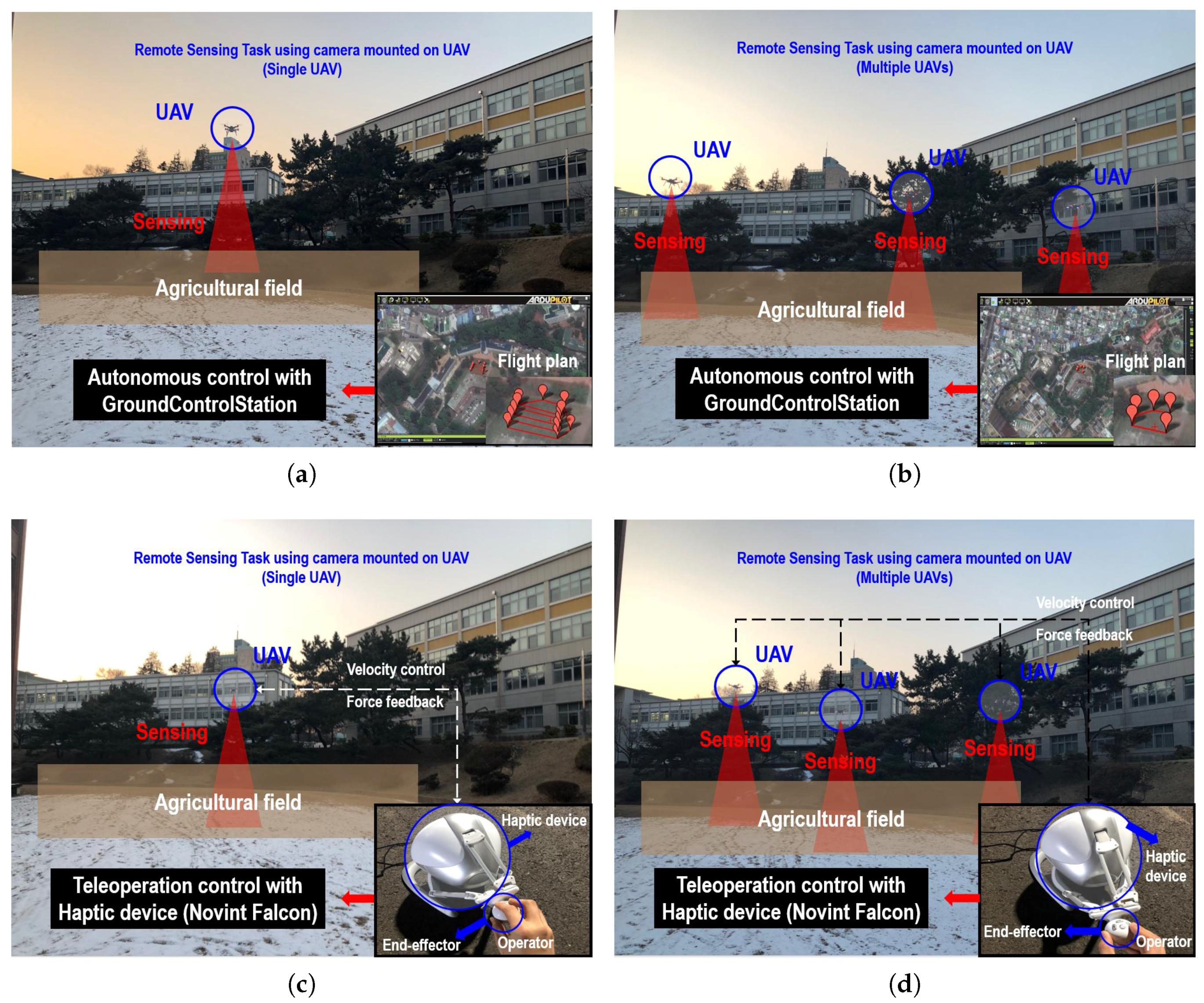
Experimental setup for experiments: Unmanned aerial vehicle (UAV) performs remote sensing task in the test area (a) case of Auto-Single-UAV (b) case of Auto-Multi-UAV (c) case of Tele-Single-UAV (d) case of Tele-Multi-UAV.
Figure 2.
Experimental setup for experiments: Unmanned aerial vehicle (UAV) performs remote sensing task in the test area (a) case of Auto-Single-UAV (b) case of Auto-Multi-UAV (c) case of Tele-Single-UAV (d) case of Tele-Multi-UAV.

Figure 3.
Quadcopter type unmanned aerial vehicle: 3DR SOLO. We attached additional hardware to the 3DR SOLO and performed a remote sensing task. The left picture is from the top view and the right is the bottom view of the 3DR SOLO.
Figure 3.
Quadcopter type unmanned aerial vehicle: 3DR SOLO. We attached additional hardware to the 3DR SOLO and performed a remote sensing task. The left picture is from the top view and the right is the bottom view of the 3DR SOLO.

Figure 4.
Scheme of multiple unmanned aerial vehicle (UAV) system: Robot operating system (ROS) based distributed system. For this, additional onboard computers were mounted on the UAV and wireless router was used for communications. In addition, the ROS based controller is mounted not only on the computer but also on the UAV.

Figure 5.
Experimental results of remote sensing for each case: Flight trajectory for one trial. (a) case of Auto-Single-UAV (b) case of Auto-Multi-UAV (c) case of Tele-Single-UAV (d) case of Tele-Multi-UAV.
Figure 5.
Experimental results of remote sensing for each case: Flight trajectory for one trial. (a) case of Auto-Single-UAV (b) case of Auto-Multi-UAV (c) case of Tele-Single-UAV (d) case of Tele-Multi-UAV.


Table 1.
Datasheet explaining reference, objective, agricultural task, UAV type, control method, sensors, and target crop for a recent study using an agricultural UAV.
Table 1.
Datasheet explaining reference, objective, agricultural task, UAV type, control method, sensors, and target crop for a recent study using an agricultural UAV.
| Reference | Objective | Task | UAV | Control | Sensors | Crop |
|---|---|---|---|---|---|---|
| B.Allred et al. [7] | Evaluation of VIS, NIR, and TIR imagery for drainage pipe mapping | Remote Sensing and Mapping | Single Fixed-wing type UAV | Ground Control Station (Auto) | Multi-spectral camera, thermal camera | Corn, Soybeans |
| L. G. Santesteban et al. [8] | To estimate the instantaneous and seasonal variability of plat water status | Remote Sensing and Mapping | Single X8 type UAV | Ground Control Station (Auto) | Multi-spectral camera, thermal camera | Vineyard |
| F. A. Vega et al. [9] | To determine the capability of an UAV system to acquire multi-temporal images | Monitoring | Single Quadcopter type UAV | Ground Control Station (Auto) | Multi-spectral camera | Sunflower |
| P. Tokekar et al. [10] | To study the problem of maximizing the number of points visited by the UAV | Remote Sensing | Single Octocopter type UAV + Single UGV | Ground Control Station (Auto) | Multi-spectral camera | Field |
| J. Torres-Sánchez et al. [11] | To report an innovative procedure for a high-throughput and detailed 3D monitoring of agricultural tree plantations | Mapping | Single Quadcopter type UAV | Remote Control (Teleoperation) | Visible-light camera, Multi-spectral camera | Olive plantation |
| A. Noriega et al. [12] | Development of a path planning method to minimize the time required to scan a field | Monitoring | Single Octocopter type UAV | Ground Control Station (Auto) | Multi-spectral camera | Field |
| B. H. Alsala et al. [13] | To describe a modular and generic system that is able to control the UAV using computer vision | Remote Sensing | Single Quadcopter type UAV | Ground Control Station (Auto) | RGB camera, Ultrasonic, Spraying system | Weed |
| R. Jannoura et al. [14] | Evaluation of crop biomass using true colour aerial photographs | Monitoring | Single Hexacopter type UAV | Remote Control (Teleoperation) | RGB camera | Pea, Oat |
| M.P. Christiansen et al. [15] | Designing and testing a UAV mapping system for agricultural field surveying | Mapping | Single Quadcopter type UAV | Ground Control Station (Auto) | RGB camera, LiDAR | Wheat |
| B. S. Faiçal et al. [16] | To propose a computer-based system that able to adapt the UAV control rules | Spraying | Single Helicopter type UAV | Ground Control Station (Auto) | Spraying control system | Field |
| J. Torres-Sánchez et al. [17] | To describes the specifications and configurations of a UAV for site-specific weed management | Remote Sensing | Single Quadcopter type UAV | Ground Control Station (Auto) | Point-and-shoot camera, Multi-spectral camera | Sunflower |
| P. J. Zarco-Tejada et al. [18] | Development of methods for leaf carotenoid content estimation, using an UAV | Remote Sensing | Single Fixed-wing type UAV | Ground Control Station (Auto) | Multi-spectral/Hyper-spectral camera | Vineyard |
| D. Doering et al. [19] | Development of an autonomous system to perform inspections for agriculture based on the use of multiple UAVs | Monitoring | Multiple Quadcopter type UAV | Ground Control Station (Auto) | RGB camara | Field |
| H. Xiang et al. [20] | Development of an automatic aerial image georeferencing method for an UAV platform | Remote Sensing | Single Helicopter type UAV | Ground Control Station (Auto) | Multi-spectral camera | Field |
| A. Barrientos et al. [21] | Practical experimentation with an integrated tool to create a full map using multiple UAVs | Area Coverage and Path Planning | Multiple Quadcopter type UAV | Ground Control Station (Auto) | IMU, Pressure sensor, GPS | Vineyard |
| J. A. Arroyo et al. [22] | To propose a model to estimate Nitrogen nutrition level in crops using agricultural UAV | Remote Sensing | Single Quadcopter type UAV | Ground Control Station (Auto) | Multi-spectral camera | Corn |
Table 2.
Experimental results for each case and performance metric.
| Metric | Auto-Single-UAV | Auto-Multi-UAV | Tele-Single-UAV | Tele-Multi-UAV |
|---|---|---|---|---|
| [s] | 96.2 | 78.8 | 65.1 | 32.6 |
| [s] | 48.7 | 64.5 | 13.5 | 18.9 |
| [s] | 47.5 | 14.3 | 51.6 | 13.7 |
| 3.9 | 1.6 | 4.2 | 1.2 | |
| [cm] | 18.0 | 19.3 | 8.2 | 13.8 |
| [cm] | 0.0 | 0.0 | 31.1 | 15.3 |
| 100.0 | 300.0 | 100.0 | 300.0 |
Table 3.
Experimental results: comparison between single-UAV system and multi-UAV system and comparison between automatic control method and teleoperation method. For example, Auto-UAV and Single → Multi, .
Table 3.
Experimental results: comparison between single-UAV system and multi-UAV system and comparison between automatic control method and teleoperation method. For example, Auto-UAV and Single → Multi, .
| Metric | Auto-UAV | Tele-UAV | Single-UAV | Multi-UAV |
|---|---|---|---|---|
| Single → Multi | Single → Multi | Auto → Tele | Auto → Tele | |
| [s] | −18.1% | −50.0% | −32.3% | −58.7% |
| [s] | +32.4% | +39.9% | −72.2% | −70.7% |
| [s] | −69.8% | −73.5% | +8.6% | −4.7% |
| −59.3% | −70.5% | +9.1% | −21.0% | |
| [cm] | +7.1% | +66.8% | −54.0% | −28.4% |
| [cm] | 0.0% | −50.9% | + | + |
| +200.0% | +200.0% | 0.0% | 0.0% |
© 2018 by the authors. Licensee MDPI, Basel, Switzerland. This article is an open access article distributed under the terms and conditions of the Creative Commons Attribution (CC BY) license (http://creativecommons.org/licenses/by/4.0/).
Share and Cite
MDPI and ACS Style
Ju, C.; Son, H.I. Multiple UAV Systems for Agricultural Applications: Control, Implementation, and Evaluation. Electronics 2018, 7, 162. https://0-doi-org.brum.beds.ac.uk/10.3390/electronics7090162
AMA Style
Ju C, Son HI. Multiple UAV Systems for Agricultural Applications: Control, Implementation, and Evaluation. Electronics. 2018; 7(9):162. https://0-doi-org.brum.beds.ac.uk/10.3390/electronics7090162
Chicago/Turabian StyleJu, Chanyoung, and Hyoung Il Son. 2018. "Multiple UAV Systems for Agricultural Applications: Control, Implementation, and Evaluation" Electronics 7, no. 9: 162. https://0-doi-org.brum.beds.ac.uk/10.3390/electronics7090162
Note that from the first issue of 2016, this journal uses article numbers instead of page numbers. See further details here.