Article

Compact UWB Band-Notched Antenna with Integrated Bluetooth for Personal Wireless Communication and UWB Applications

by
MuhibUr Rahman
1,
Mahdi NagshvarianJahromi
2,
Seyed Sajad Mirjavadi
3,* and
Abdel Magid Hamouda
3,*
1
Department of Electrical Engineering, Polytechnique Montreal, Montreal, QC H3T 1J4, Canada
2
Department of Electrical and Computer Engineering, McMaster University, Hamilton, ON L8S 4L8, Canada
3
Department of Mechanical and Industrial Engineering, College of Engineering, Qatar University, P. O. Box 2713 Doha, Qatar
*
Authors to whom correspondence should be addressed.
Submission received: 24 November 2018 / Revised: 25 December 2018 / Accepted: 14 January 2019 / Published: 1 February 2019
(This article belongs to the Special Issue Intelligent Antennas)

Abstract

:
A compact band-notched UWB (Ultra-Wide Band) antenna with integrated Bluetooth is developed for personal wireless communication and UWB applications. The antenna operates at the UWB frequency band (3.1–10.6 GHz) as well as Bluetooth (2.4–2.484 GHz), with band-notch characteristics at the Wireless Local Area Network (WLAN) frequency band (5–6 GHz). A new technique of integrating Bluetooth within a UWB band-notched antenna is developed and analyzed. The UWB frequency band is realized by utilizing a conventional cylindrical radiating patch and a modified partial ground plane. The Bluetooth band is integrated using a miniaturized resonator with the addition of capacitors. Further, to mitigate the interference of the WLAN frequency band within the UWB spectrum, a conventional slot resonator is integrated within the radiator to achieve the task. The antenna is designed and fabricated, and its response in each case is provided. Moreover, the antenna exhibits a good radiation pattern with a stable gain in the passband. The present antenna is also compared to state-of-the-art structures proposed in the literature. The miniaturized dimensions (30 × 31 mm2) of the antenna make it an excellent candidate for UWB and personal wireless communication applications.

1. Introduction

UWB (Ultra-Wide Band) antennas have been a main technological interest for the last decade due to their large bandwidth, small electrical size, good phase linearity, low cost, and advantageous radiation pattern [1,2,3,4,5]. Wireless Personal Area Network (WPAN) technology with an IEEE 802.15 standard target can deliver reliable and high-speed communication between portable devices, computers, and other electronic applications in a short range. The development of UWB communication technology offers an encouraging solution for the IEEE 802.15 standard of WPAN. In 2001, IEEE 802.15 provided the foundation for an IEEE 802.15.3a Study Group, who attempted to define a new standard for WPAN based on a physical layer of UWB that increased their bit rates to 500 Mbps [6].
The SIG (Special Interest Group) of Bluetooth selected the WiMedia Alliance MB-OFDM (Multiband orthogonal frequency division multiplexing) version of UWB in 2006, which made it possible to integrate UWB with Bluetooth. Subsequently, researchers started to integrate Bluetooth within UWB antennas [7].
Since 2002, the Federal Communication Commission (FCC) has allowed the use of UWB communication within the frequency spectrum of 3.1–10.6 GHz [8]. However, due to the broader frequency range of UWB, different interfering frequency bands fall within the UWB spectrum. The WLAN frequency band, which operates at 5–6 GHz, also falls within the UWB range and causes electromagnetic interference. For this reason, a tremendous amount of research has been performed on band-notched UWB antennas; single, dual, triple, quadruple, and quintuple band-notched UWB antennas have been proposed [9,10,11,12,13,14,15]. These antennas possess the ability to filter the interfering bands by using slot resonators, complementary split ring resonators, split ring resonators, parasitic strips, defected ground structures (DGS), integrating filters with antennas, or a combination of these techniques [15,16,17,18,19,20,21,22,23,24,25].
Moreover, there has been a tremendous amount of research on switching notched bands of UWB antennas as presented in [26], where they designed an innovative resonator for switching between single/dual and continuously tunable behavior. Also, there has been research performed on the integration of Bluetooth and UWB antennas [27,28,29,30]. In [27], they designed a low profile and small-sized planar UWB antenna with integrated Bluetooth. The finished antenna was claimed to operate from 2.40–2.48 GHz and 3.1–10 GHz for the Bluetooth and UWB bands, respectively. They integrated Bluetooth within the UWB antenna by applying a stub loaded resonator. The antenna exhibited a good radiation pattern. However, the antenna was bulky in size, with dimensions of 42 × 46 mm2 fed by a 50 Ohm microstrip-fed line. Similarly, in [28] they designed a UWB antenna and integrated Bluetooth to operate at 2.40–2.48 GHz and 3.1–10.6 GHz. The UWB antenna was designed using the conventional octagonal patch and modified ground plane. A quarter wavelength strip resonator was introduced at the center of the patch to integrate Bluetooth within the UWB antenna. Subsequently, they inserted a slot resonator in the feedline to achieve band-notching. The size of this antenna was 38 × 30 × 1.6 mm3 with a good time domain resolution. Similarly, in [29] they proposed an antenna for UWB and Bluetooth with notched bands at 5/5.5 GHz and 7.2/7.6 GHz. Dual notched bands were realized by etching one slot resonator in the feedline of the antenna. The transmission-line-based metamaterial (TL-MTM) was also loaded with the antenna to achieve Bluetooth operation. The size of the antenna was bulky due to the loading of TL-MTM and its dimensions of 38.5 × 46.4 mm2. Moreover, the antenna operated at the 2.43–2.49 (Bluetooth) and 3.1–10.6 (UWB) frequency bands with good radiation characteristics.
Likewise, in [31] they designed a UWB antenna and then integrated Bluetooth by loading a quarter wavelength resonator at the center of the antenna. The overall size of the antenna was 50 × 24 × 1.6 mm3 and operated at 3.1–11.4 (UWB) and 2.18–2.59 (Bluetooth). In [32], they tried to design and analyze a Bluetooth integrated UWB band-notched antenna using parasitic strips. The overall size of the antenna was 46 × 20 × 1.0 mm3 and operated at 3.1–10.6 (UWB) and 2.40–2.48 (Bluetooth). They also introduced two conventional arc-shaped slot resonators in the patch to achieve band-notching at the WLAN frequency band. Since this antenna was loaded by a parasitic strip at the side of the feedline, it also exhibited coupling at the UWB frequency band. Due to this coupling, the antenna had a deteriorated radiation pattern at the UWB frequency band, which became more dominant at higher frequencies. The author in [33] developed a fork-shaped printed UWB antenna with integrated Bluetooth. The overall size of the antenna was 42 × 24 × 1.6 mm3 and operated at 3.1–12 GHz (UWB) and 2.30–2.50 GHz (Bluetooth). They used the conventional technique of loading a quarter wavelength strip in the middle of the designed UWB antenna. Similarly, in [34] they designed a miniaturized UWB antenna with integrated Bluetooth. The Bluetooth was integrated using a strip line to the circular patch. The overall size of the antenna was 45 × 32 × 1.0 mm3 and operated at 3.1–10.6 GHz (UWB) and 2.40–2.50 GHz (Bluetooth). Since the Bluetooth was realized using strip loading, the radiation patterns greatly deteriorated at higher frequencies of the UWB band. In [35], they used split ring resonators, which were placed on both sides of the feedline, on the front side of the antenna. The Bluetooth was achieved using these split ring resonators. However, they affected the radiation performance as explained above. Nevertheless, no one has tried to integrate Bluetooth within the UWB using a resonator with the addition of capacitors.
In this paper, a miniaturized UWB band-notched antenna operating at the UWB and Bluetooth frequency bands is developed. This antenna operates well from 2.4–2.484 GHz and 3.1–10.6 GHz, with a band-notched frequency band for WLAN suppression. The miniaturized resonator is utilized to integrate the Bluetooth band within the UWB band in an innovative way. First, a conventional UWB antenna is designed and then modified to a single notched antenna using a slot resonator. Then, a resonance band for Bluetooth is generated within a single notched antenna using the combination of the miniaturized resonator with capacitors.
This study is organized as follows: Section 2 outlines the antenna’s geometries and design guidelines along with the resonator analysis. Section 3 comprises the results and discussions in terms of the reflection coefficient of the designed antennas in Section 2. Section 3 also covers the measurement and fabrication of the Bluetooth integrated UWB band-notched antenna. Section 4, which is followed by a conclusion, illustrates the originality of the proposed technique compared to other state-of-the-art designs.

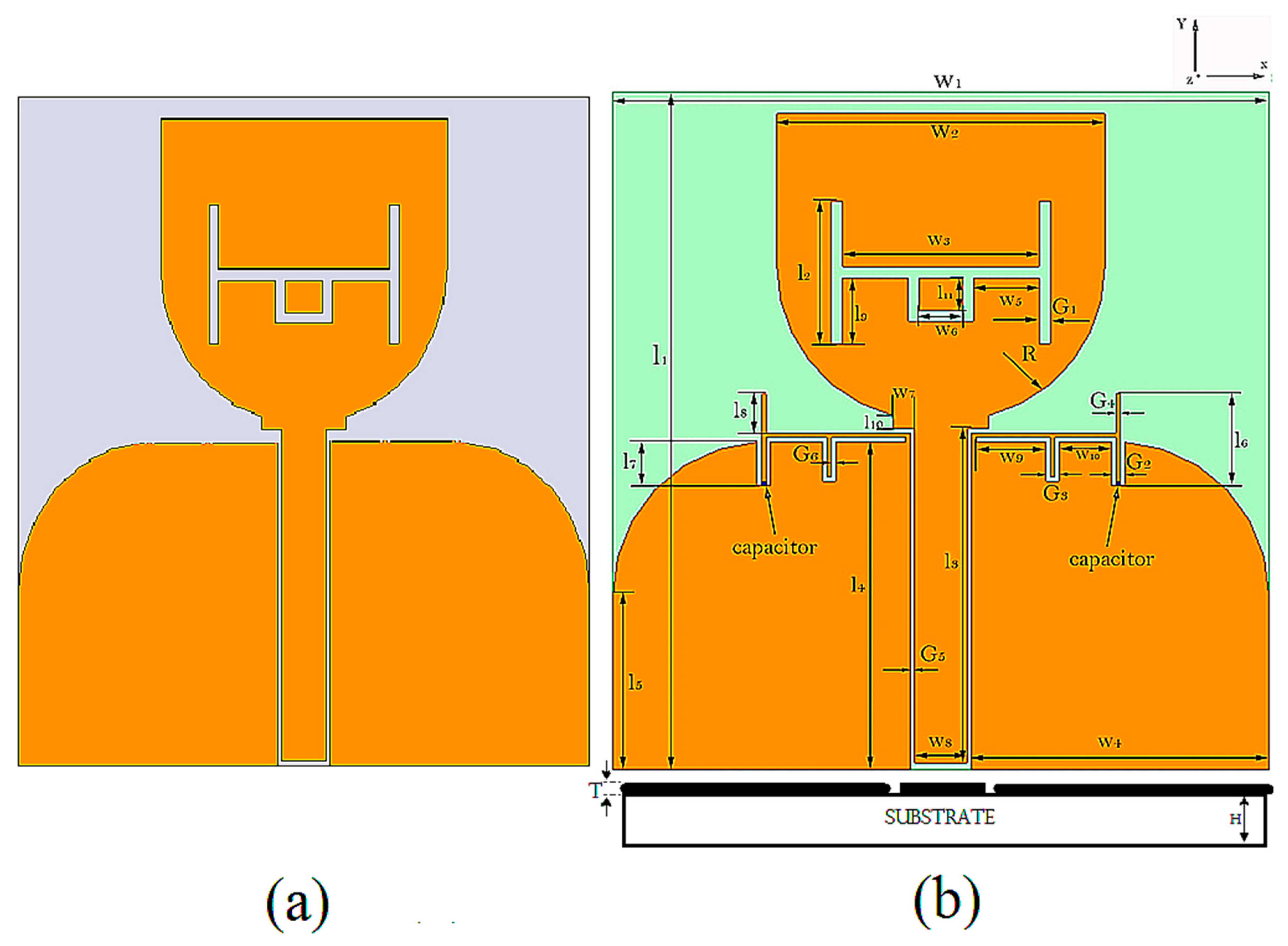
2. Design Geometry and Analysis of the Resonator

Figure 1a shows the conventional reference UWB antenna designed using [26]. It features a radiator combined with a rectangular and semi-circular patch with an edge-curved modified ground plane. The radiating patch is fed by a 50 Ohm CPW line. The reference antenna was also fabricated for validation purposes, and its prototype is shown in Figure 1b. The antenna was designed on a Rogers RO4003 substrate with a thickness of 1.5 mm and a relative dielectric constant of εr = 3.38.
Figure 2a shows the single notched UWB antenna with a filtering effect at the WLAN frequency band and is termed as Antenna 1. This antenna was designed using a conventional slot resonator with an effective length equivalent to a half wavelength at the center frequency of 5.5 GHz. A miniaturized slot resonator was introduced in the partial ground plane with an effective length corresponding to 3.0 GHz. This antenna is termed as Antenna 2. An antenna was then designed to integrate Bluetooth within the single notched UWB antenna and is termed Antenna 3, as shown in Figure 2b. This antenna consists of a miniaturized resonator with integrated capacitors of 0.5 pF. The dimensions and other important design parameters of the final structure are shown in Figure 2b and mentioned in Table 1.

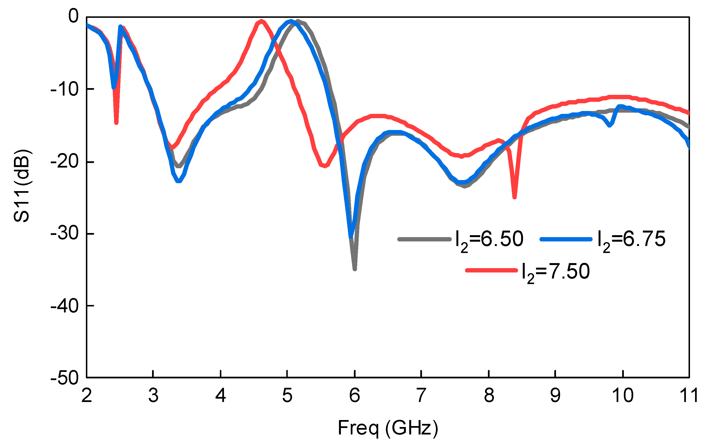
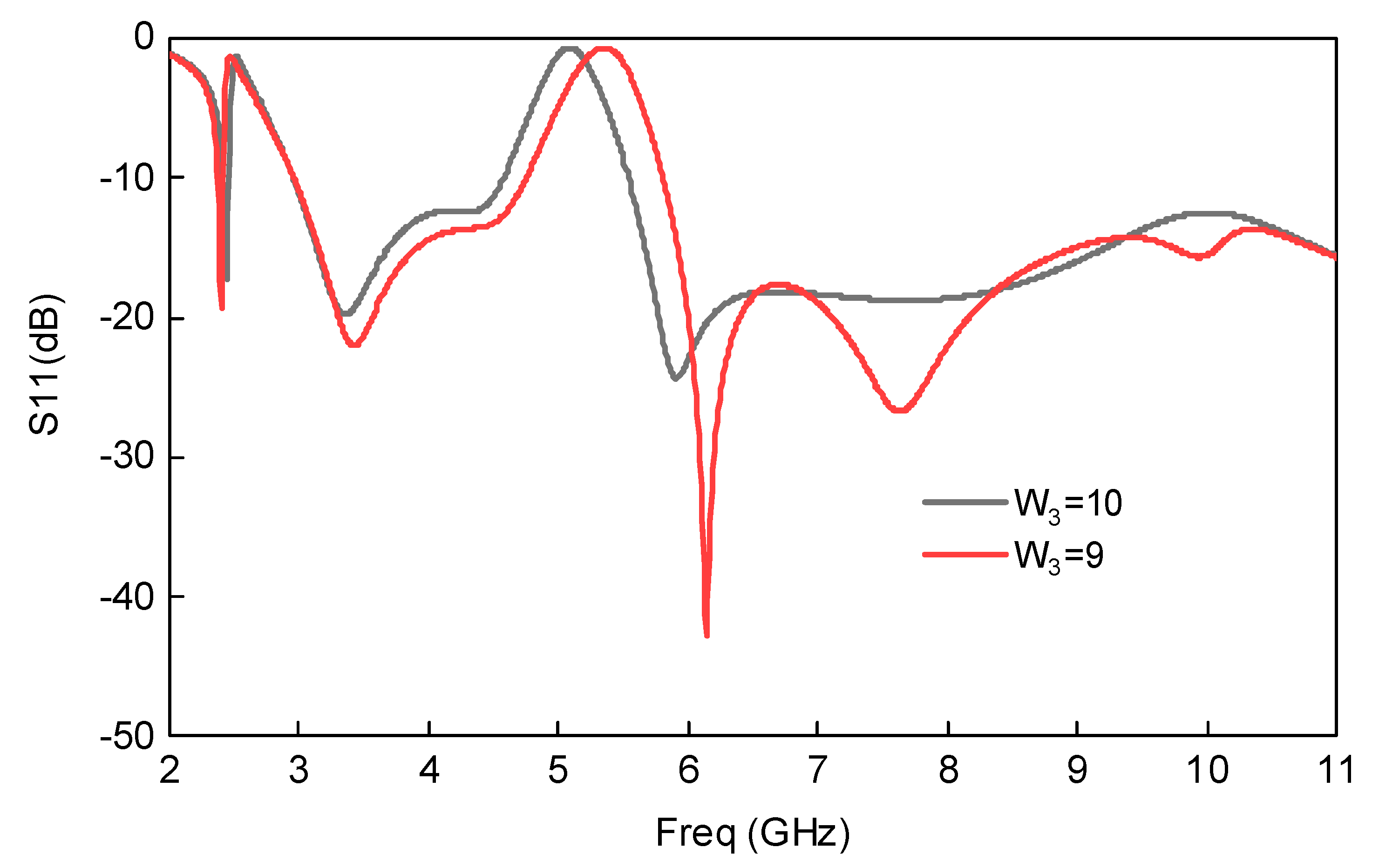
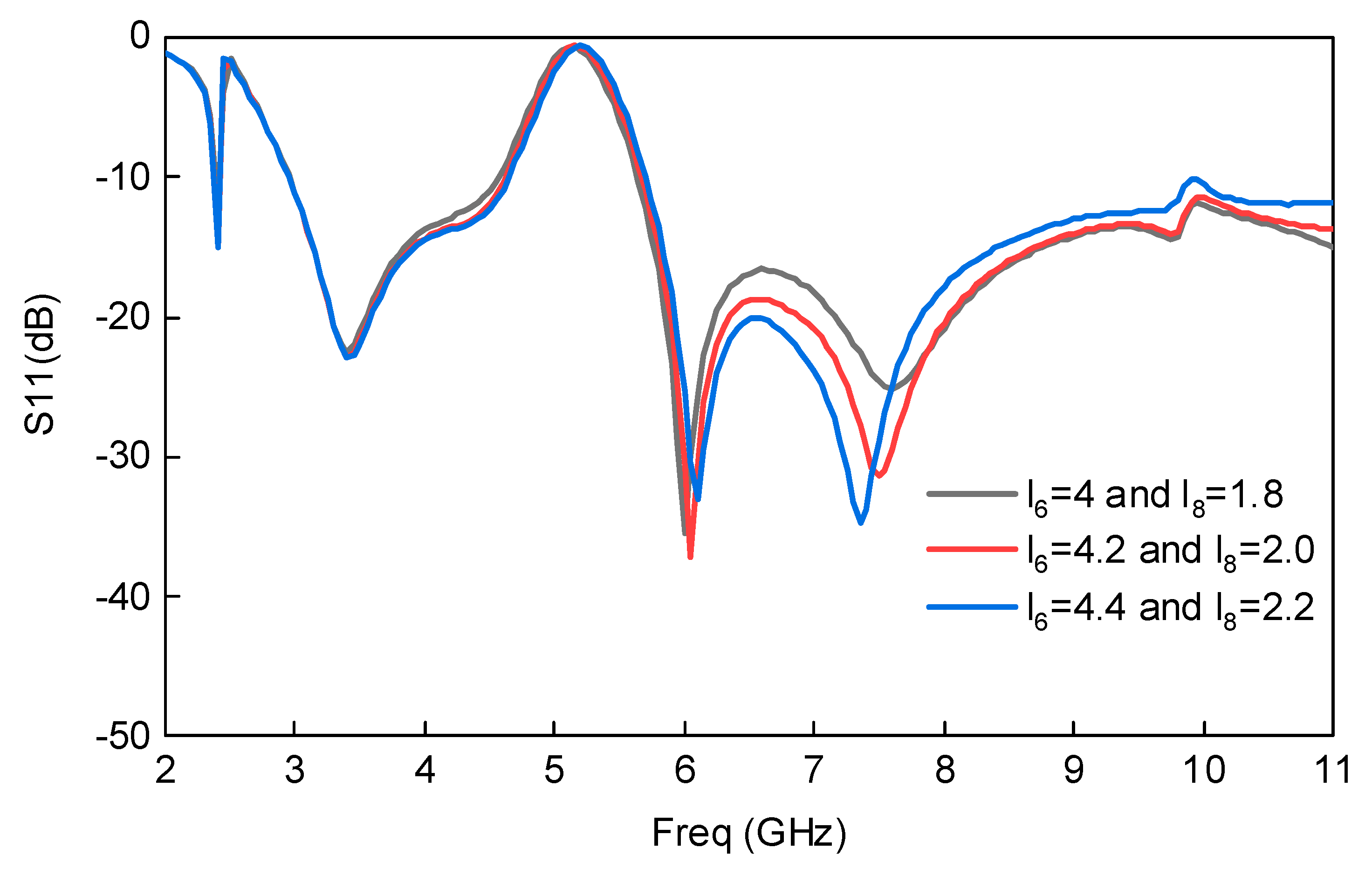
Analysis of the Implemented Resonators

For the initial choice of the resonator placed within the radiating patch, the design Equation implemented at a desired notched band frequency fnotch (5.5 GHz) is calculated using the following Equation:
W 3 + W 6 + 2 ( l 2 + l 11 ) = c 2 f n o t c h ε e f f
where, ε e f f for this resonator is calculated using the Equation below:
ε e f f = ε r + 1 2 + ε r 1 2 ( 1 + 12 h w f ) 0.5
The resonator integrated to achieve Bluetooth within a single notched UWB antenna was also investigated and analyzed. The effective permittivity, ɛeff′, and effective permeability, µeff, for this resonator can be determined using the following relations [26,36]:
Γ = k ± k 2 1
k = S 11 2 S 21 2 + 1 2 S 11
Z e f f = μ e f f ε e f f = ( 1 + Γ 1 Γ ) Z T L Z a T L
n = n j n = ε e f f μ e f f = ± c j ω l cos h 1 ( 1 S 11 2 S 21 2 2 S 21 )
ε e f f = ε e f f j ε e f f = n Z e f f
μ e f f = μ e f f j μ e f f = n × Z e f f
where Z T L represents the reference transmission line characteristic impedance and Γ is the reflection coefficient, while Z a T L represents the transmission line impedance when filled with air, n signifies the refractive index, and l represents the effective length of the miniaturized resonator. The overall length of the miniaturized resonator is almost half of the guided wavelength at 3 GHz (where λg represents the guided medium wavelength), while the coefficient signifies coupling, which can be given as n = Z ( c p w ) Z o s , where Zos signifies the slot resonator impedance and Z(cpw) represents the CPW fed line impedance. We determined the resonator’s reflection coefficient (S11) and transmission coefficient (S21) by considering the resonator as a matched two-port network. When the capacitor value (Cap) is 0 pF, the resonator behaves as an open circuit and resonates at 3.0 GHz. Increasing the Cap to 0.5 pF shifts the 3 GHz frequency band towards the lower frequency and generates another resonance passband at 2.45 GHz.

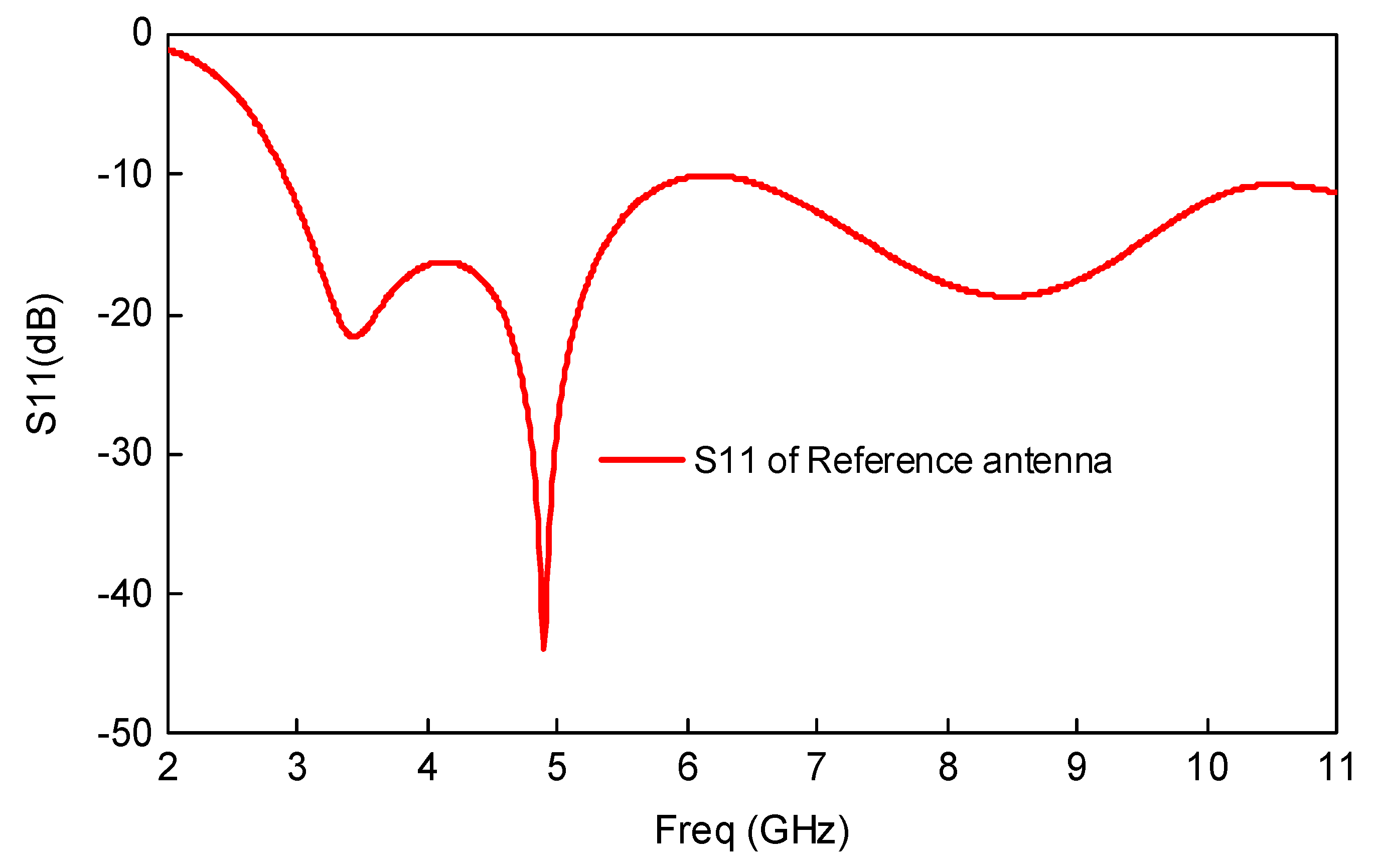
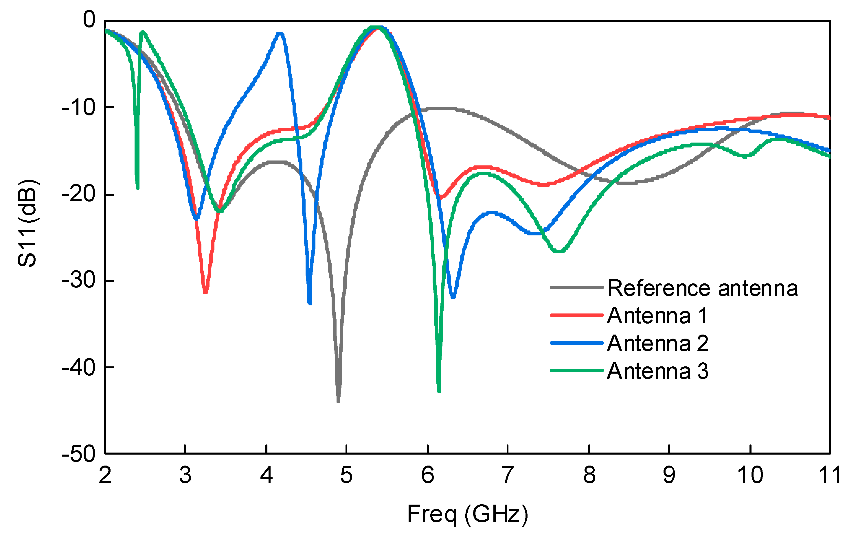
3. Results and Discussions

The above antennas were designed and optimized using the commercially available EM software, Ansoft HFSS. The reference antenna was simulated and successfully covered the whole UWB frequency spectrum. The reflection coefficient of the reference UWB antenna is shown in Figure 3, which clarifies that antenna operated from 3.1 GHz to 10.6 GHz. Next, a single notched UWB antenna was designed using the conventional slot resonator technique. The effective length of the slot resonator corresponds to the 5.5 GHz center frequency of the WLAN frequency band. Furthermore, the slot resonator was optimized parametrically, and the response is shown in Figure 4. A miniaturized novel resonator was subsequently introduced to the partial ground plane whose effective length corresponded to the 3.0 GHz frequency band and was analyzed using Equations (1)–(6). This antenna was termed Antenna 2; its response is also shown in Figure 4. A Bluetooth integrated UWB band-notched antenna was then developed by introducing capacitors within the miniaturized resonator. The value of the capacitor was also adjusted and optimized parametrically. This antenna is termed Antenna 3; its reflection coefficient plot is shown in Figure 4, which shows that Antenna 3 operated at the UWB frequency band (3.1–10.6 GHz), as well as Bluetooth (2.4–2.484 GHz), with band-notch characteristics at the WLAN frequency band (5–6 GHz).

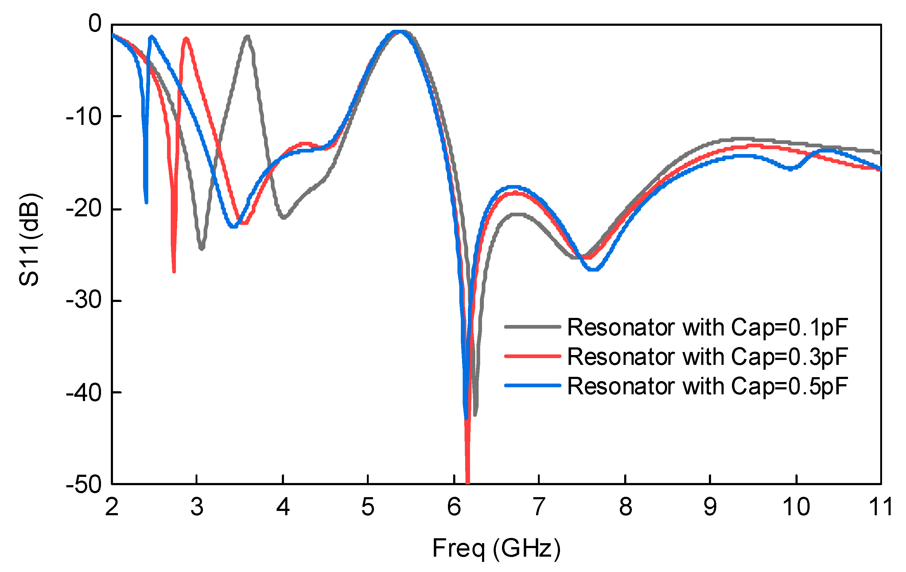
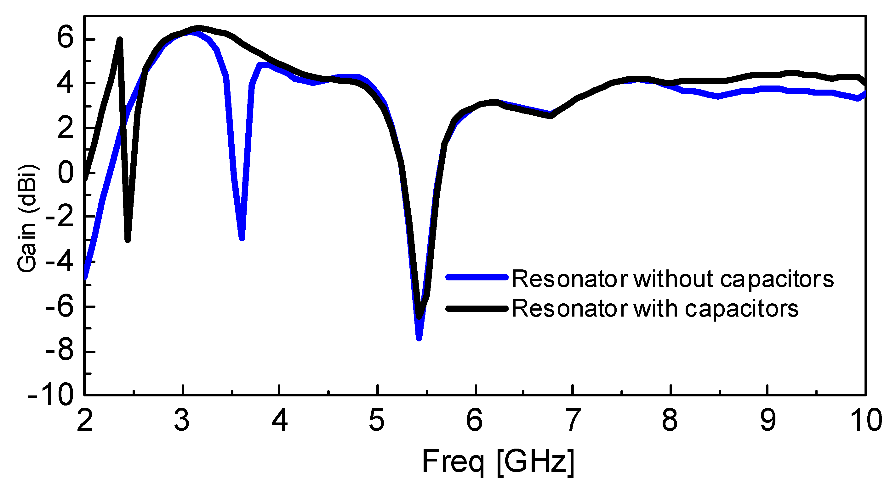
3.1. Optimizing the Capacitor Values and the Antenna’s Response Comparison

The capacitor values were optimized parametrically by changing from 0.1 pF to 0.5 pF. It is well known that increasing the capacitor value within the resonator will shift the passband towards the lower frequencies, as increasing the capacitor value also increases the resonator’s effective length. This concept was utilized, and the capacitors were integrated within the miniaturized resonator. The position of the capacitor was also optimized. At capacitor value = 0.3 pF, the passband is almost shifted to 2.7 GHz, and by further increasing its value to 0.5 pF, the passband is shifted to 2.45 GHz. The trend of frequency shifting can be clearly seen in Figure 5. The reference antenna and other three antenna’s responses were correlated and plotted in one figure to properly understand the concept. This comparison of the antenna’s response is shown in Figure 4. As investigated earlier, adding a capacitor within the resonator shifts the resonance towards the lower frequency bands due to an increase in the electrical length of the resonator [37].
The effect of variable l2 on the response of the Bluetooth integrated UWB antenna is also analyzed parametrically and shown in Figure 6. As Figure 6 demonstrates, increasing l2 also shifts the WLAN notched band towards the lower frequencies provided in Equation (1). Similar phenomena were also observed for W3, W6, and l11, as mentioned in Equation (1). To validate these results, the length of W3 was slightly increased, as shown in Figure 7. The same behavior was observed as the WLAN notched band shifted towards lower frequencies. These parameters (shown in Figure 6 and Figure 7, respectively) had no effect on the integrated Bluetooth band. The variables l6 and l8 had a very minor effect on the response of the antenna, as shown in Figure 8. However, l6 was chosen in such a way that it had symmetrical strips on the top and bottom, which is further represented by l8.
Both l6 and l8 were placed in the partial ground plane, which had no effect on the radiation performance of the antenna. This antenna was advantageous in terms of placing a resonator, which did not deteriorate the antenna’s radiation performance, in the ground plane. l6 and l8 were important for placing the notched band, but they were also noteworthy because they had no effect on radiation performance. On the other hand, l2 and W3 effected radiation performance because they were placed in the radiating element.

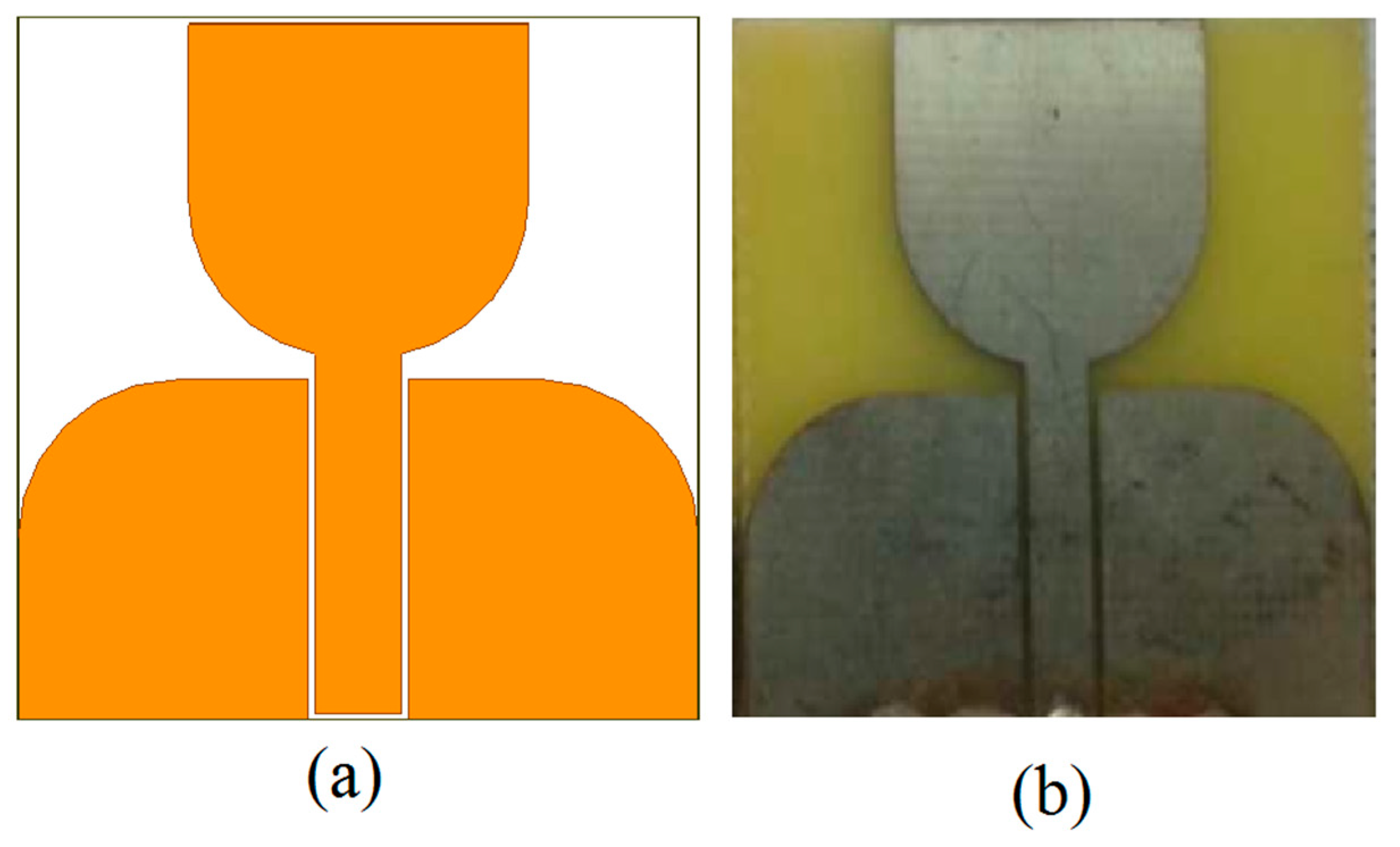
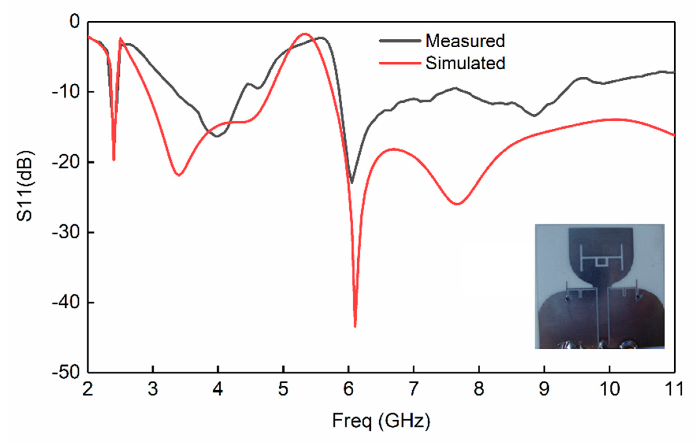
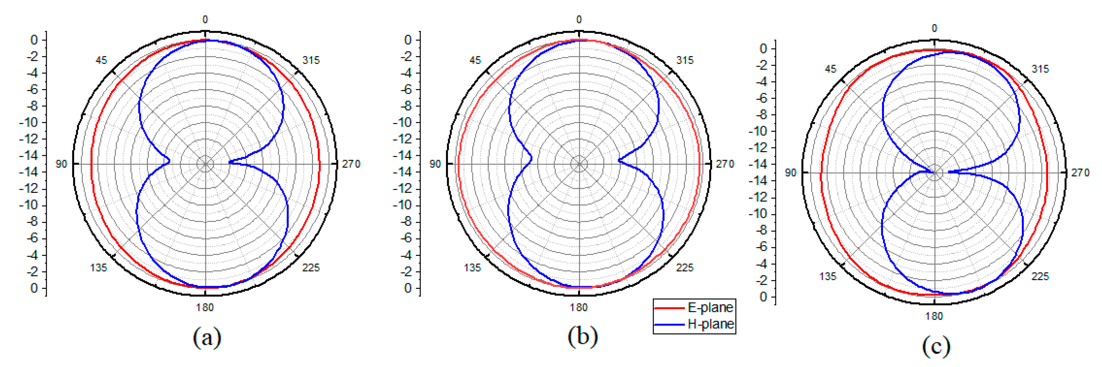
3.2. Fabrication and Measurement of the BluetoothIintegrated UWB Band-Notched Antenna

The Bluetooth integrated UWB band-notched antenna was also fabricated and measured. The measured response was compared with the simulated one. The comparison in Figure 9 shows that the measured results corresponded very well at both the UWB and Bluetooth bands. However, at higher frequencies of the UWB band there was a shift away from the simulated response. Nevertheless, this response was valid and workable.
The measured radiation patterns of the Bluetooth integrated band-notched UWB antenna at different frequencies were measured in an anechoic chamber corresponding to frequencies 2.45 GHz (Bluetooth), 4.6 GHz (UWB), and 7.2 GHz (UWB). The E-plane and H-plane measured radiation patterns are displayed in Figure 10. The setup was adjusted in such a way that the radiation patterns at both planes were measured at each one-degree step size. As previously seen in [12], increasing the measurement points and decreasing the step size greatly enhanced the uniformity and pattern factor. The measured radiation pattern was consistent and clean at both the Bluetooth and UWB frequency bands.
The simulated gain of the UWB antenna with integrated Bluetooth is also provided in Figure 11. The antenna shows a very stable gain in the passbands, which include 2.45 GHz (Bluetooth) and 3.1–10.6 GHz (UWB). Suppression in the antenna gain can also be seen on the WLAN frequency band, which further validates the notching behavior. Moreover, the antenna gain correlates to the case resonator integrated with and without capacitors in Figure 11.

4. Comparison with Other State-of-the-Art Designs

The developed technique of integrating Bluetooth within a UWB band-notched antenna was also compared with the related literature in terms of antenna dimensions, operating frequency bands, dielectric constant, and method of integration. This comparison is listed in Table 2, which also reveals that the present antenna has an advantage over the other designs based on of the selected parameters. Moreover, our method of integrating a certain frequency band within the designed antenna differs significantly from previous work.

5. Conclusions

A simple and compact band-notched UWB (Ultra-Wide Band) antenna with integrated Bluetooth was developed for personal wireless communication and UWB applications. The antenna operates at the UWB frequency band (3.1–10.6 GHz) as well as with Bluetooth (2.4–2.484 GHz) with band-notch characteristics at the WLAN frequency band (5–6 GHz). A new way to integrate Bluetooth within a UWB band-notched antenna has been developed and analyzed. The Bluetooth band is integrated within a UWB antenna using a miniaturized resonator with the addition of capacitors. A conventional slot resonator is also integrated within the radiator to remove WLAN interference. The antenna is designed as well as fabricated, and the simulated response is correlated with the measured one. The antenna exhibits a good radiation pattern with a stable gain in the passband. The miniaturized dimensions (30×31mm2) of the antenna will make it an excellent candidate for UWB and personal wireless communication applications.

Author Contributions

All authors contributed equally to the development of the design, theory, concept, fabrication, and measurements.

Acknowledgments

The publication of this article was funded by the Qatar National Library. Seyed Sajad Mirjavadi also appreciates the help from the Fidar Project Qaem Company (FPQ).

Conflicts of Interest

The authors declare that there is no conflict of interest regarding this publication.

References

  1. Feng, H.; Xu, L.; Wang, P.; Gao, P. Miniaturized UWB Monopole-Like Slot Antenna with Low Un-Roundness of H-Plane Radiation Patterns at High-Frequency Band. Progress Electromagn. Res. 2017, 70, 107–113. [Google Scholar] [CrossRef]
  2. Islam, M.M.; Islam, M.T.; Faruque, M.R.I.; Samsuzzaman, M.; Misran, N.; Arshad, H. Microwave Imaging Sensor Using Compact Metamaterial UWB Antenna with a High Correlation Factor. Materials 2015, 8, 4631–4651. [Google Scholar] [CrossRef] [PubMed] [Green Version]
  3. NejatiJahromi, M.; NagshvarianJahromi, M.; Rahman, M. A New Compact Planar Antenna for Switching between UWB, Narrow Band and UWB with Tunable-notch Behaviors for UWB and WLAN Applications. Appl. Comput. Electromagn. Soc. J. 2018, 33, 400–406. [Google Scholar]
  4. Rahman, M. CPW fed miniaturized UWB tri-notch antenna with bandwidth enhancement. Adv. Electr. Eng. 2016, 2016, 7279056. [Google Scholar] [CrossRef]
  5. Alibakhshikenari, M.; Virdee, B.S.; Shukla, P.; See, C.H.; Abd-Alhameed, R.; Khalily, M.; Falcone, F.; Limiti, E. Antenna Mutual Coupling Suppression Over Wideband Using Embedded Periphery Slot for Antenna Arrays. Electronics 2018, 7, 198. [Google Scholar] [CrossRef]
  6. Arslan, H.; Chen, Z.N.; di Bendetto, M.G. Ultrawideband Wireless Communication; Wiley Interscience: Hoboken, NJ, USA, 2006. [Google Scholar]
  7. Labade, R.P.; Deosarkar, D.S.B.; Pishoroty, D.N.; Malahotra, D.A. Compact band notched printed monopole antenna for ultrawideband communication. In Proceedings of the IEEE Conference INDICON (2014), Pune, India, 1–13 December 2014. [Google Scholar]
  8. The Federal Communications Commission. Revision of Part 15 of the Commission’s Rules Regarding Ultra-Wideband Transmission Systems; First Report and Order, FCC 02–48, 22 April 2002; The Federal Communications Commission: Washington, DC, USA, 2002.
  9. Gao, G.; Hu, B.; He, L.; Wang, S.; Yang, C. Investigation of a reconfigurable dual notched UWB antenna by conceptual circuit model and time-domain characteristics. Microw. Opt. Technol. Lett. 2017, 59, 1326–1332. [Google Scholar] [CrossRef]
  10. NejatiJahromi, M.; NagshvarianJahromi, M.; Rahman, M. Compact CPW Fed Switchable UWB Antenna as an Antenna Filter at Narrow-Frequency Bands. Progress Electromagn. Res. C 2018, 81, 199–209. [Google Scholar] [CrossRef]
  11. Rahman, M.; Ko, D.S.; Park, J.D. A Compact Multiple Notched Ultra-Wide Band Antenna with an Analysis of the CSRR-TO-CSRR Coupling for Portable UWB Applications. Sensors 2017, 17, 2174. [Google Scholar] [CrossRef] [PubMed]
  12. Rahman, M.; Park, J.-D. The Smallest Form Factor UWB Antenna with Quintuple Rejection Bands for IoT Applications Utilizing RSRR and RCSRR. Sensors 2018, 18, 911. [Google Scholar] [CrossRef]
  13. Jafari, H.M.; Deen, M.J.; Hranilovic, S.; Nikolova, N.K. A study of ultrawideband antennas for near-field imaging. IEEE Trans. Antennas Propag. 2007, 55, 1184–1188. [Google Scholar] [CrossRef]
  14. Rahman, M.; Khan, W.T.; Imran, M. Penta-notched UWB antenna with sharp frequency edge selectivity using combination of SRR, CSRR, and DGS. AEU Int. J. Electron. Commun. 2018, 93, 116–122. [Google Scholar] [CrossRef]
  15. Nejatijahromi, M.; Rahman, M.; Naghshvarianjahromi, M. Continuously Tunable WiMAX Band-Notched UWB Antenna with Fixed WLAN Notched Band. Progress Electromagn. Res. Lett. 2018, 75, 97–103. [Google Scholar] [CrossRef]
  16. Rahman, M.; Khan, W.T.; Imran, M.; Awais, M. Time domain analysis of a compact UWB antenna acting as a band stop filter in five narrow frequency bands. In Proceedings of the 2017 IEEE Asia-Pacific Microwave Conference, Kuala Lumpur, Malaysia, 13–16 November 2017; pp. 783–786. [Google Scholar]
  17. NejatiJahromi, M.; NagshvarianJahromi, M.; Rahman, M. Switchable planar monopole antenna between ultra-wideband and narrow band behavior. Progress Electromagn. Res. Letters 2018, 75, 131–137. [Google Scholar] [CrossRef]
  18. Liu, X.L.; Yin, Y.Z.; Liu, P.A.; Wang, J.H.; Xu, B. A CPW-fed dual band-notched UWB antenna with a pair of bended dual-L-shape parasitic branches. Progress Electromagn. Res. 2013, 136, 623–634. [Google Scholar] [CrossRef]
  19. Azim, R.; Islam, M.-T. Compact planar UWB antenna with band notch characteristics for WLAN and DSRC. Progress Electromagn. Res. 2013, 133, 391–406. [Google Scholar] [CrossRef]
  20. Lotfi, P.; Azarmanesh, M.; Soltani, S. Rotatable dual band-notched UWB/triple-band WLAN reconfigurable antenna. IEEE Antennas Wirel. Propag. Lett. 2013, 12, 104–107. [Google Scholar] [CrossRef]
  21. Emadian, S.R.; Ghobadi, C.; Nourinia, J.; Mirmozafari, M.H.; Pourahmadazar, J. Bandwidth enhancement of CPW-fed circle-like slot antenna with dual band-notched characteristic. IEEE Antennas Wirel. Propag. Lett. 2012, 11, 543–546. [Google Scholar] [CrossRef]
  22. Fallahi, R.; Kalteh, A.A.; Roozbahani, M.G. A novel UWB elliptical slot antenna with band-notched characteristics. Progress Electromagn. Res. 2008, 82, 127–136. [Google Scholar] [CrossRef]
  23. Ding, J.; Lin, Z.; Ying, Z.; He, S. A compact ultra-wideband slot antenna with multiple notch frequency bands. Microw. Opt. Technol. Lett. 2007, 49, 3056–3060. [Google Scholar] [CrossRef]
  24. Rahman, M.; NaghshvarianJahromi, M.; Mirjavadi, S.S.; Hamouda, A.M. Bandwidth Enhancement and Frequency Scanning Array Antenna Using Novel UWB Filter Integration Technique for OFDM UWB Radar Applications in Wireless Vital Signs Monitoring. Sensors 2018, 18, 3155. [Google Scholar] [CrossRef]
  25. Yadav, S.; Gautam, A.K.; Kanaujia, B.K. Design of dual band-notched lamp-shaped antenna with UWB characteristics. Int. J. Microw. Wirel. Technol. 2015, 9, 395–402. [Google Scholar] [CrossRef]
  26. Rahman, M.; NaghshvarianJahromi, M.; Mirjavadi, S.S.; Hamouda, A.M. Resonator Based Switching Technique between Ultra Wide Band (UWB) and Single/Dual Continuously Tunable-Notch Behaviors in UWB Radar for Wireless Vital Signs Monitoring. Sensors 2018, 18, 3330. [Google Scholar] [CrossRef] [PubMed]
  27. Yildirim, B.S.; Cetiner, B.A.; Roqueta, G.; Jofre, L. Integrated bluetooth and UWB antenna. IEEE Antennas Wirel. Propag. Lett. 2009, 8, 149–152. [Google Scholar] [CrossRef]
  28. Labade, R.; Deosarkar, S.; Pisharoty, N.; Malhotra, A. Compact integrated bluetooth UWB bandnotch antenna for personal wireless communication. Microw. Opt. Technol. Lett. 2016, 58, 540–546. [Google Scholar] [CrossRef]
  29. Li, W.; Hei, Y.; Feng, W.; Shi, X. Planar antenna for 3G/bluetooth/WiMAX and UWB applications with dual bandnotched characteristics. IEEE Antennas Wirel. Propag. Lett. 2012, 11, 61–64. [Google Scholar]
  30. Kang, X.; Zhang, H.; Li, Z.; Guo, X.; Wang, J.; Yang, Y. A band notched UWB printed half elliptical ring monopole antenna. Progress Electromagn. Res. B 2013, 35, 23–33. [Google Scholar] [CrossRef]
  31. Mandal, T.; Das, S. Design of a microstrip fed printed monopole antenna for bluetooth and UWB applications with WLAN notch band characteristics. Int. J. RF Microw. Comput. Aided Des. 2015, 25, 66–74. [Google Scholar] [CrossRef]
  32. Li, Z.Q.; Ruan, C.L.; Peng, L. Design and analysis of planar antenna with dual WLAN band-notched for integrated bluetooth and UWB applications. J. Electromagn. Waves Appl. 2010, 24, 1817–1828. [Google Scholar]
  33. Mishra, S.K.; Gupta, R.K.; Vaidya, A.; Mukherjee, J. A compact dual-band fork-shaped monopole antenna for Bluetooth and UWB applications. IEEE Antennas Wirel. Propag. Lett. 2011, 10, 627–630. [Google Scholar] [CrossRef]
  34. Zhan, K.; Guo, Q.; Huang, K. A miniature planar antenna for Bluetooth and UWB applications. J. Electromagn. Waves Appl. 2010, 24, 2299–2308. [Google Scholar] [CrossRef]
  35. Xiong, L.; Gao, P. Dual-band planar monopole antenna for bluetooth and UWB applications with WiMAX and WLAN band-notched. Progress Electromagn. Res. 2012, 28, 183–194. [Google Scholar] [CrossRef]
  36. NaghshvarianJahromi, M.; Ghorabani, A. On the behavior of compact ultrawideband tunable bandwidth semicomplementary split ring resonator bandpass filter. Microw. Opt. Technol. Lett. 2015, 57, 256–263. [Google Scholar] [CrossRef]
  37. Khidre, A.; Yang, F.; Elsherbeni, A.Z. A patch antenna with a varactor-loaded slot for reconfigurable dual-band operation. IEEE Trans. Antennas Propag. 2015, 63, 755–760. [Google Scholar] [CrossRef]
Figure 1. (a) Reference UWB antenna and (b) prototype of reference UWB antenna.
Electronics 08 00158 g001
Figure 2. (a) Band-notched UWB antenna (Antenna 1) and (b) Bluetooth integrated UWB antenna (Antenna 2 when no capacitors are integrated into the resonator and Antenna 3 when the capacitor = 0.5 pF).
Electronics 08 00158 g002
Figure 3. The reflection coefficient of the reference UWB antenna.
Electronics 08 00158 g003
Figure 4. Comparison between the above-designed antenna’s behavior in terms of the reflection coefficient.
Electronics 08 00158 g004
Figure 5. The reflection coefficient of the UWB antenna that included an integrated resonator with Cap variation from 0.1 pF to 0.5 pF.
Electronics 08 00158 g005
Figure 6. Parametric analysis of variable l2 and its effect on the response of the antenna.
Electronics 08 00158 g006
Figure 7. Effect of variable W3 on the response of the antenna.
Electronics 08 00158 g007
Figure 8. Effect of variable l6 and l8 on the response of the antenna.
Electronics 08 00158 g008
Figure 9. Comparison between the measured and simulated reflection coefficients of the UWB band-notch antenna with integrated Bluetooth.
Electronics 08 00158 g009
Figure 10. Measured radiation pattern of the UWB antenna with integrated Bluetooth; (a) 2.45 GHz, (b) 4.60 GHz, (c) 7.20 GHz.
Electronics 08 00158 g010
Figure 11. Antenna Gain (dBi) in case of resonator with and without capacitors.
Electronics 08 00158 g011
Table 1. Dimensions of the UWB band-notched antenna with integrated Bluetooth (all values are in mm).
ParameterValueParameterValueParameterValueParameterValue
W130W71L131L93
W215W82.40L26.5L100.61
W39W93.2L58L111.5
W413.59W102.4L64G10.5
W53L6.5L71.98G2 = G30.6
W62R8L81.8G4 = G5 = G60.2
Table 2. Performance comparison with other designs in the literature.
Ref.Implemented TechniqueAntenna Size (mm3)Dielectric ConstantOperating Frequency (GHz)
[17]Inverted L-resonator30.5 × 24 × 1.53.383.1–10.6
[18]L-shaped bended branch40 × 30 × 1.24.43.1–11
[19]Annular slot26 × 24 × 1.64.63–10.6
[20]Rectangular slots16 × 14 × 14.43.2–10.0
[21]Circular slots30 × 26 × 1.64.42.5–11
[22]Inverted U-strip50 × 45 × 1.276.03.1–10.6
[23]Split ring resonators30 × 26 × 1.63.52.4–10.1
[25]Lamp shaped antenna28×15×1.64.42.7–14.0
[26]Cap. Integrated antenna30.5 × 24 × 1.53.383.1–10.6
[27]L-shaped stub46 × 42 × 14.43.1-10.6
[28]Loading quarter wavelength resonating strip38 × 30 × 1.64.43.1–10.6
2.4–2.5
[29]Loading TL-MTM within UWB antenna38.5 × 46.4 × 1.64.43.1–10.6
2.43–2.49
[30]No integration52 × 32 × 1.64.43.1–10.6
[31]Loading quarter wavelength resonating strip at the center of the patch50 × 24 × 1.64.43.1–11.4
2.18–2.59
[32]Loading parasitic strip46 × 20 × 1.02.43.1–10.6
2.40–2.48
[33]Loading quarter wavelength resonating strip at the center of the patch42 × 24 × 1.64.43.1–12.0
2.30–2.50
[34]Loading strip-line to the patch45 × 32 × 1.04.43.1–10.6
2.40–2.50
This workCapacitors loaded miniaturized resonator in the ground plane30 × 31 × 1.53.383.1–10.6
2.4–2.48

