A Modified Control Scheme for Power Management in an AC Microgrid with Integration of Multiple Nanogrids


Electrical Engineering, Visvesvaraya National Institute of Technology, Nagpur 440010, India
*
Author to whom correspondence should be addressed.
Electronics 2019, 8(5), 490; https://0-doi-org.brum.beds.ac.uk/10.3390/electronics8050490
Submission received: 16 March 2019
/
Revised: 25 April 2019
/
Accepted: 25 April 2019
/
Published: 30 April 2019
(This article belongs to the Section Power Electronics)
Abstract
:This paper proposes a modified control scheme for a grid connected microgrid, which is contrived by integrating multiple nanogrids. In the considered system, each nanogrid consists of a generation unit from solar photovoltaic (PV) along with battery energy storage (BES) system and local loads. The nanogrid has the flexibility to operate in microgrid connected mode or islanded operating mode. Similarly, the microgrid can also be operated in grid connected mode or islanded mode. To achieve appropriate load sharing between different nanogrids considering local load demands and source power availability, a modified control scheme is developed. The proposed scheme compensates for the required reactive power, harmonics and unbalanced currents locally which are demanded by the local loads in nanogrids in order to improve the power quality in the microgrid. The smooth transition between the modes of operation of nanogrids and microgrid is achieved with the proposed modified control scheme. In addition, the proposed modified control scheme allows the microgrid and main grid to remain free from transients generated by load disturbances in nanogrid and disturbances in the microgrid respectively. Therefore, the effect of disturbances on voltage and frequency of the microgrid is reduced. A simple control scheme is developed to address the challenging issues for smooth operation of the microgrid such as active power sharing among the sources based on their ratings, power quality enhancement (compensation of harmonic components, unbalanced current and reactive power) and seamless transition between the modes of operation (during islanding from grid and re-synchronisation with grid). The performance of the proposed modified control scheme is verified in a real time simulator during variable loading conditions.
1. Introduction
The utilisation of renewable energy sources (RESs) is increased due to depletion in fossil fuels and global warming. The power generated from solar is increasing, but it is not in the usable form, because of variable dc voltage. Therefore, a power electronic interface is used in between the RES source and the system. The RES along with power electronic interface is connected to the system as distributed generation (DG). These are located near to the loads. To increase the reliability in the system, DG should provide a reliable supply to the local loads. The DG and local loads together constitute a nanogrid. A nanogrid can be termed as a small microgrid which is spread over a small geographical area with smaller capacity. It must have at least a single load and often has an energy storage associated to it. A cluster of these nanogrids are interconnected to form a microgrid [1,2,3]. The microgrid can operate in grid connected mode or in islanded mode/stand-alone mode. An intelligent control technique is required for load sharing among the DGs in the microgrid based on their ratings [4].
The challenging issues for smooth operation of a microgrid are active power sharing among the sources based on their ratings, power quality enhancement (compensation of harmonic components, unbalanced current and reactive power) and smooth transition between the modes of operation (during islanding from grid and re-synchronisation with grid). To address the aforesaid issues, different control schemes are presented in the literature [5,6].
For decentralised control, the droop method is used for load sharing. Here, DGs are controlled as voltage control sources. The reference voltage for the controller is estimated from the droop equations. The load sharing among the DGs is done based on their respective droop constants. The droop constants of DGs are defined based on their ratings [7,8]. The conventional droop method is more sensitive to the line impedance. To overcome this issue, a virtual impedance is added in the controller [9,10]. Whenever the total nominal power of DGs and total load demand are unequal, then the operating voltage and frequency of microgrid is other than a nominal value. To restore the voltage and frequency of the microgrid to its nominal value, a hierarchial control is developed in [11,12,13]. In the droop method, the non-linear loads are shared by extracting the harmonic components of current and by adding additional control loops in the controller [14,15]. Similarly, the unbalanced loads are shared by extracting the symmetrical components (positive and negative sequence) [16,17]. Therefore, the droop method becomes complex to implement if there is a variation in line impedance, non-linear load demand, unbalanced load demand and mismatch between total power generation & total load demand. In this method, a smooth transition will occur when a microgrid disconnects from the main grid and operates in islanded mode. However, the transition of the microgrid from the islanded mode to grid connected mode is quite complex. In [18,19,20,21,22], seamless transition is achieved during the transition of microgrid from islanded mode to grid connected mode by developing different intelligent techniques.
Average power sharing method, concentrated control and master-slave control are the other load sharing techniques which are presented in the literature [4]. In average power sharing method and concentrated control, the power sharing among the DGs are equal. In master-slave method, one DG will be controlled as voltage source; which acts as master DG and the remaining DGs will act as slaves. The co-ordination between the DGs in the microgrid is controlled by centralised controller [23,24]. In grid connected operating mode, DGs in the microgrid are controlled as slaves. During this mode, the main grid maintains the system voltage. The transients in the microgrid are taken care by the main grid, by this the burden on main grid will increase when multiple microgrids are connected to main grid. The single microgrid disturbance will not affect the main grid because it has high inertia. However, disturbance due to multiple microgrids will affect the main grid and burden will increase. In islanded operating mode, one DG which have higher power rating among the DGs in the microgrid will maintain the system voltage by acting as master DG and the remaining act as slaves by injecting the reference power which is obtained from the centralised controller. The total transients will be handled by the master DG during the disturbances in the microgrid. Therefore, the burden on master DG is more as compared to other DGs in the microgrid [25,26]. The main drawback of master-slave method is that the functioning of microgrid is mainly dependent on the master DG, which implies that if master DG fails then system has to shutdown.
This paper proposes a modified control scheme for the microgrid (which is contrived by integrating multiple nanogrids) to improve dynamic performance under the disturbances. In addition, it also address the challenging issues for smooth operation of the microgrid such as active power sharing among the sources based on their ratings, power quality enhancement (compensation of harmonic components, unbalanced current and reactive power) and seamless transition between the modes of operation (during islanding from grid and re-synchronisation with grid). The proposed control for DG in the nanogrids achieve the transient free operation of the microgrid, which is unaffected by the nanogrid disturbances and constant loading of the microgrid in the main grid during grid connected mode of operation. The seamless transition is achieved with reduced complexity during changeover of operating modes of nanogrids and microgrid. The microgrid power quality is enhanced by compensating the harmonic currents, unbalanced current and reactive power demand locally in the nanogrid.
The major contributions of this paper are
- The nanogrid demands constant active power from the microgrid, despite the variation in active power demand in the nanogrid. Therefore, the microgrid is unaffected from the nanogrid disturbances and the burden on master DG is reduced.
- The reactive power demand in the nanogrid is compensated locally; therefore, the effect of reactive power demand on the microgrid voltage is avoided and hence voltage profile of microgrid is improved.
- The nanogrid demands balanced current from the microgrid even though the load demand in the nanogrid is unbalanced, which avoids three phase voltage unbalance in the system.
- The voltage distortion due to non-linear loads is minimized by compensating the harmonics current locally in the nanogrid to improve power quality in the microgrid.
- The smooth transition is achieved during the change in operating modes of nanogrid and microgrid; therefore, critical loads in the nanogrid remains unaffected during the transition period. The reliability of the microgrid and nanogrid is improved.
- The disturbances occurred in the microgrid will not be reflected in the main grid, which makes the main grid transient free from the microgrid disturbances.
2. System Configuration
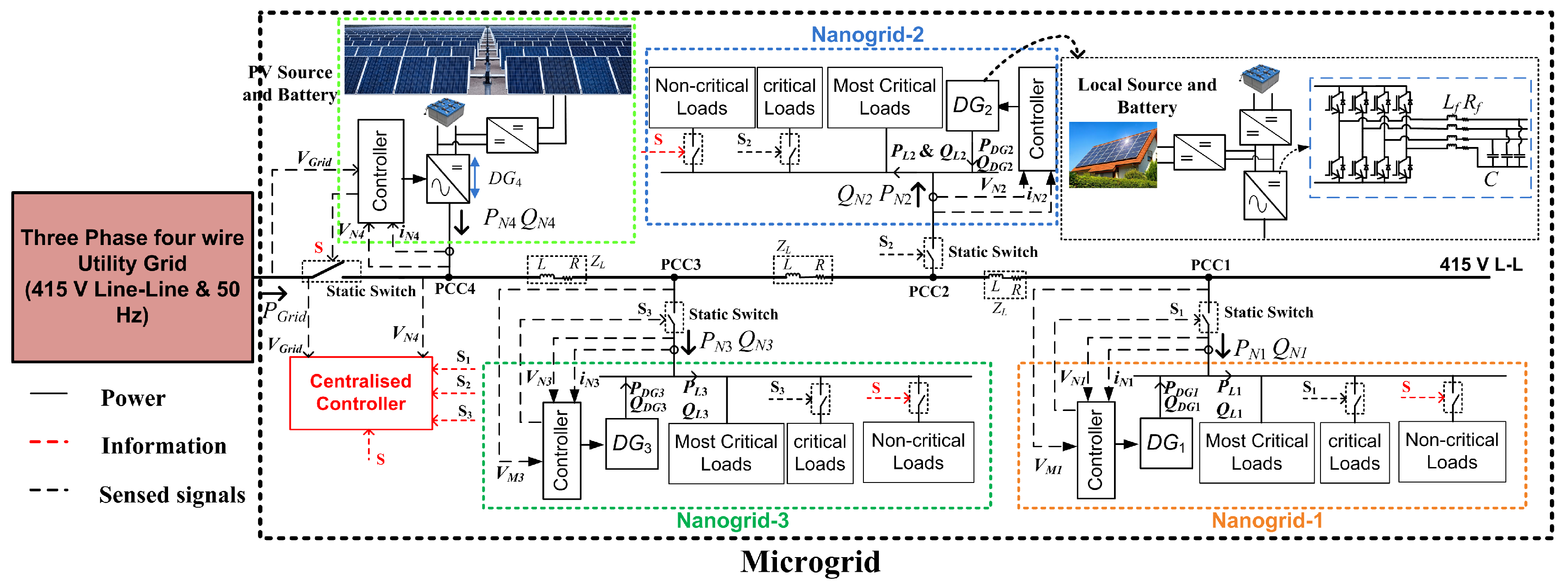
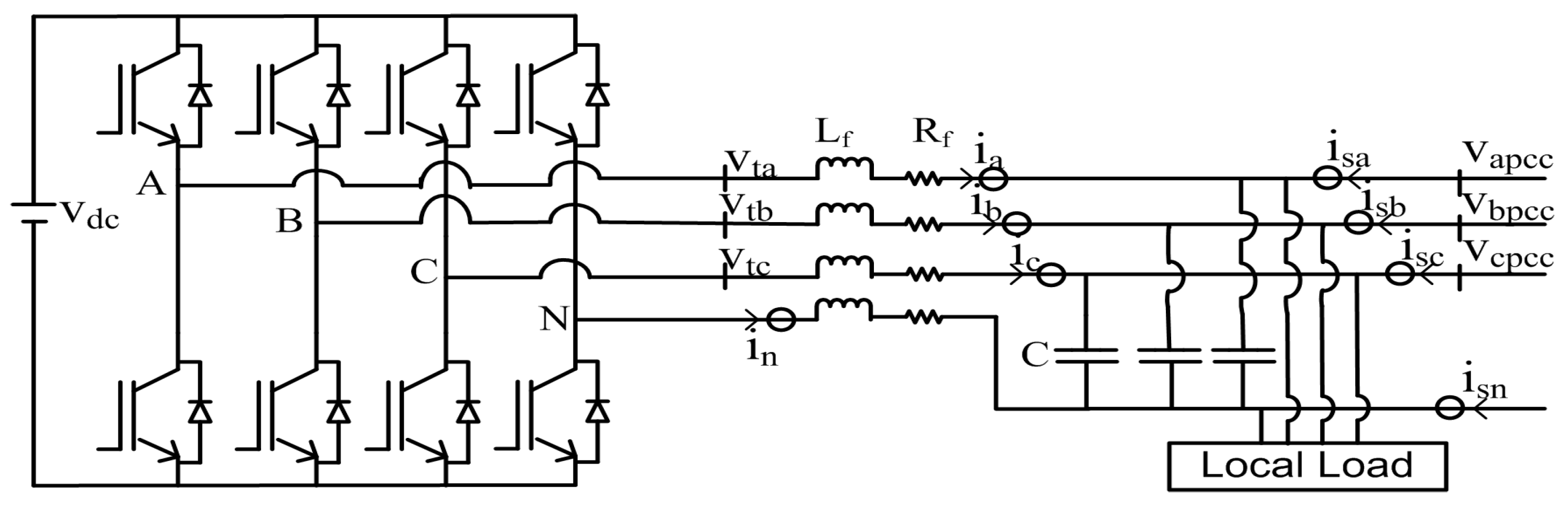
Figure 1 represents the schematic of proposed microgrid, which consists of solar PV along with battery storage system and multiple nanogrids. The nanogrid is a combination of roof top PV system, battery storage, voltage source converter (VSC) and local loads. The VSC output side have low pass LC filter (interfacing inductor with internal resistance and capacitor ) as shown in Figure 2. Each nanogrid is connected to microgrid through static switch. The nanogrid can operate in microgrid connected or islanded mode. Similarly, the microgrid is connected to the utility grid through a static switch and can operate either in grid connected mode or islanded mode. In Figure 1, signal S is a control signal for static switch of microgrid and non-critical loads. The signals , and are the control signals for the respective nanogrid static switch and critical loads.
3. Proposed Modified Control Scheme
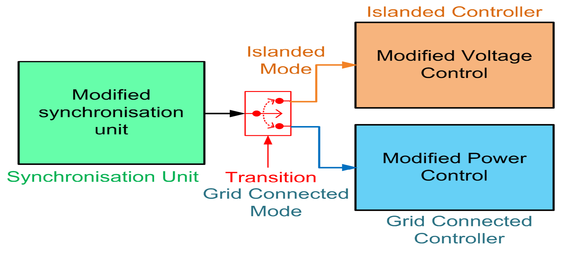
The modified control scheme is shown in Figure 3. The controller is developed for a DG such that it can operate either in grid connected mode or islanded mode. During grid connected mode, the DGs are controlled by proposed power control scheme. If any fault occurs in main grid, then the microgrid operate in islanded mode by getting disconnected from the main grid. During islanding of microgrid from main grid, the controller of is switched to modified voltage control technique as shown in Figure 3. The remaining DGs controller in the microgrid will not change their status; which are controlled by proposed power control scheme. After the clearance of the fault in the main grid, the microgrid will reconnect to the main grid by switching the controller of to proposed power control scheme. Whenever a fault occurs in the microgrid, the nanogrid disconnects from the microgrid and operates in islanded operating mode by switching the controller of respective DG to modified voltage control technique as shown in Figure 3. After the clearance of the fault in the microgrid, the nanogrid will reconnect to microgrid by switching the controller of respective DG to proposed power control scheme.
3.1. Proposed Modified Voltage Control Technique
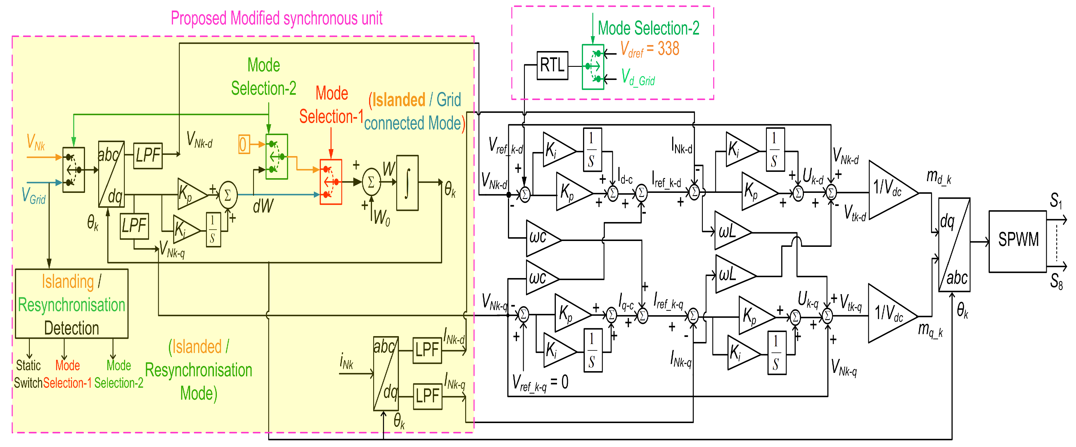
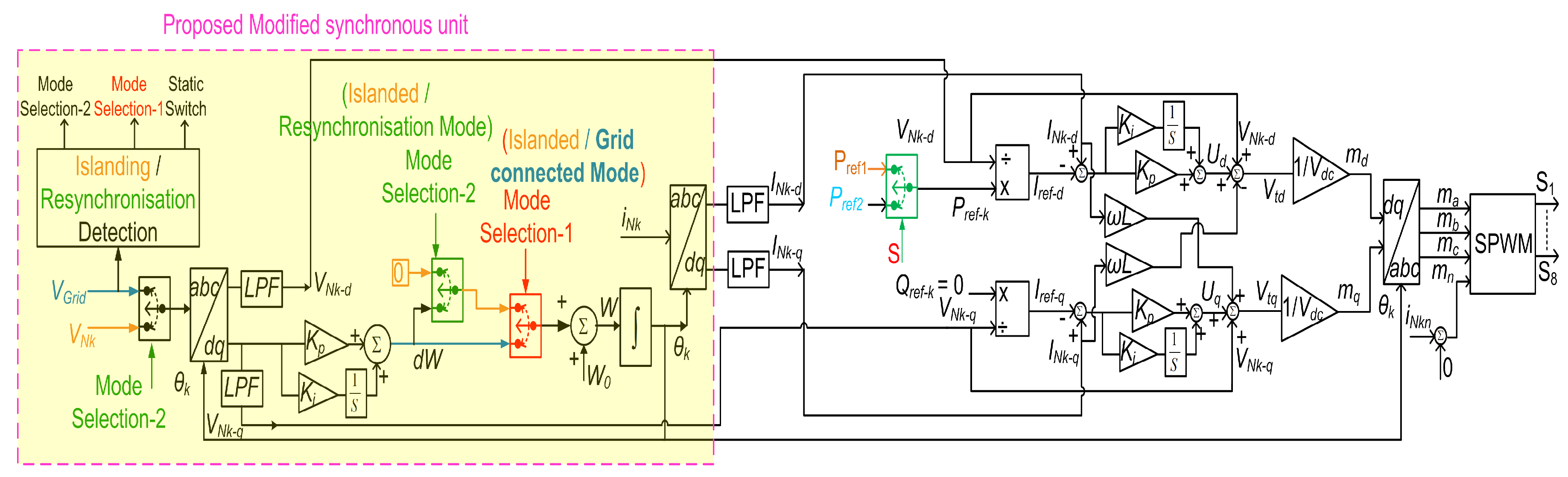
The modified synchronisation unit is developed to achieve smooth transition during islanding and re-synchronisation with the main grid. The block diagram of the modified synchronisation unit is shown in Figure 4. When the microgrid is operating in grid connected mode, the DGs in the microgrid will operate in power control mode. The instantaneous phase for reference signal is estimated from the synchronous reference frame (SRF) phase lock loop (PLL). During this period the input signal for the PLL is taken from respective PCC voltage. If any fault occurs in the main grid, then the microgrid will disconnect from main grid by controlling the static switch; which is controlled by . The controller of is switched to the modified voltage control mode with the help of mode-1 signal. When the controller of DG changes from power control mode to voltage control mode, then there is phase jump in the microgrid voltage; because the instantaneous phase for reference signal to the is generating independently at 50 Hz with rated nominal voltage. In order to avoid the phase jump, the reference signal instantaneous phase generate at the rate of 50 Hz independently; but the rise starts at previous instantaneous phase of the main grid before disconnecting. The mode-1 signal as shown in Figure 4 helps to avoid the phase jump. When fault is cleared in the main grid, the microgrid voltage will synchronise with main grid voltage before reconnecting the microgrid to main grid by generating mode-2 signal as shown in Figure 4. Similarly, the seamless transition will occur in the nanogrid during islanding and re-synchronisation with the microgrid.
The will be controlled as voltage source in the islanded mode. To maintain the reference voltage () at respective DG output, the controller is implemented.
where, . The schematic of VSC of DG is shown in Figure 2. To regulate the output voltage, the reference current through capacitor is,
In (4), is a state variable. The control variable , is obtained by passing the error between the actual voltage () and the reference voltage () through proportional plus integral (PI) controller,
In Figure 2, the output voltage equation of VSC is
The Equation (7) is converted into -frame,
The Equation (8) can be rewritten as,
In (9), is a state variable. The control variable is obtained by passing the error between the actual current () and the reference current () through the PI controller
The terminal voltage of VSC in terms of -frame modulating index is,
The (14) and (15) are converted from SRF frame to -frame, for generating the PWM signals to VSC. The block diagram is developed by using the equations from (1) to (15), as shown in Figure 4. In islanded mode, the reference voltage signal for the controller is generated at 50 Hz independently with nominal rated voltage. During the re-synchronisation of microgrid with the main grid, the grid voltage is taken as reference to the controller. From this, the microgrid voltage and the main grid voltage are maintained at same magnitude and phase. However, the sudden change in reference voltage signal causes the voltage spike from the controller in the microgrid to get the desired voltage. In order to overcome the aforementioned issue, the reference signal is passed through the rate limiter (RTL) as shown in Figure 4.
3.2. Proposed Modified Power Control Scheme
In grid connected operating mode, all DGs in the microgrid are controlled by using the modified power control scheme as shown in Figure 5. However in islanded mode, except the master DG; the remaining DGs are controlled by modified power control scheme. This controller is proposed to achieve
- The system is immune to local disturbances. The nanogrid disturbances will not be reflected in the microgrid and similarly the microgrid disturbances will not be reflected in the main grid.
- The reactive power demands are compensated locally.
- The non-linear and unbalanced load will not affect the microgrid and the main grid.
The feedback signals for the proposed power control scheme are respective PCC voltage and nanogrid current which are supplied by the microgrid. The DG in the nanogrid is controlled to maintain constant power demand from the microgrid despite the variation in local load demand. The constant power demand value is estimated from the average load demand in the nanogrid with the help of prior knowledge.
where is the average power demand of nanogrid local loads and is reference power for nanogrid local DG.
Each nanogrid has non-critical loads, critical loads and most critical loads. In the islanded operating mode of nanogrid, the most critical loads are only connected because of limitations in local power generation capacity. Whenever, the nanogrid gets connected to the microgrid, then the critical loads are connected in the nanogrid. The reference power value () in islanded mode is estimated from the average load demand of critical loads in the nanogrid. Whenever the microgrid is connected to the main grid, then all loads (most critical, critical and non-critical loads) are connected in the nanogrid. The reference power value () in grid connected mode is estimated from the average load demand of the critical loads and non-critical loads in the nanogrid.
The SRF PLL is used to obtain the respective PCC voltage instantaneous phase. The proposed power control scheme is developed in -frame. The instantaneous phase of PCC voltage is used to transform the PCC voltage and nanogrid current in -frame. In the proposed power control scheme, the reference current is
The nanogrid demands only the active power from the microgrid, the local DG compensates for the reactive power demand in the nanogrid; therefore, the reference current is
By using (17) and (18), the reference currents are estimated. Once the reference currents are estimated, then the modulating signals are obtained by using Equations (7)–(15); which are required to generate the pulses for the VSC of respective DG. The proposed power control scheme block diagram is shown in Figure 5.
4. The Proposed Microgrid Performance Evaluation
The proposed microgrid is implemented in real time simulator (OPAL-RT) to evaluate the performance of modified control technique. The parameters of proposed microgrid are shown in Table 1. The proposed control scheme is developed in discrete mode. The step size for discrete time is taken as 30 s. The ode3 (Bogacki-Shampine) solver is used. The proposed modified control technique performance is evaluated during the following operating conditions
- Nanogrids in grid connected operation mode.
- Transition of nanogrid between grid connected and islanded operation mode.
- Microgrid in grid connected operation mode.
- Transition of microgrid between grid connected and islanded operation mode.
4.1. Nanogrids in Grid Connected Operation Mode
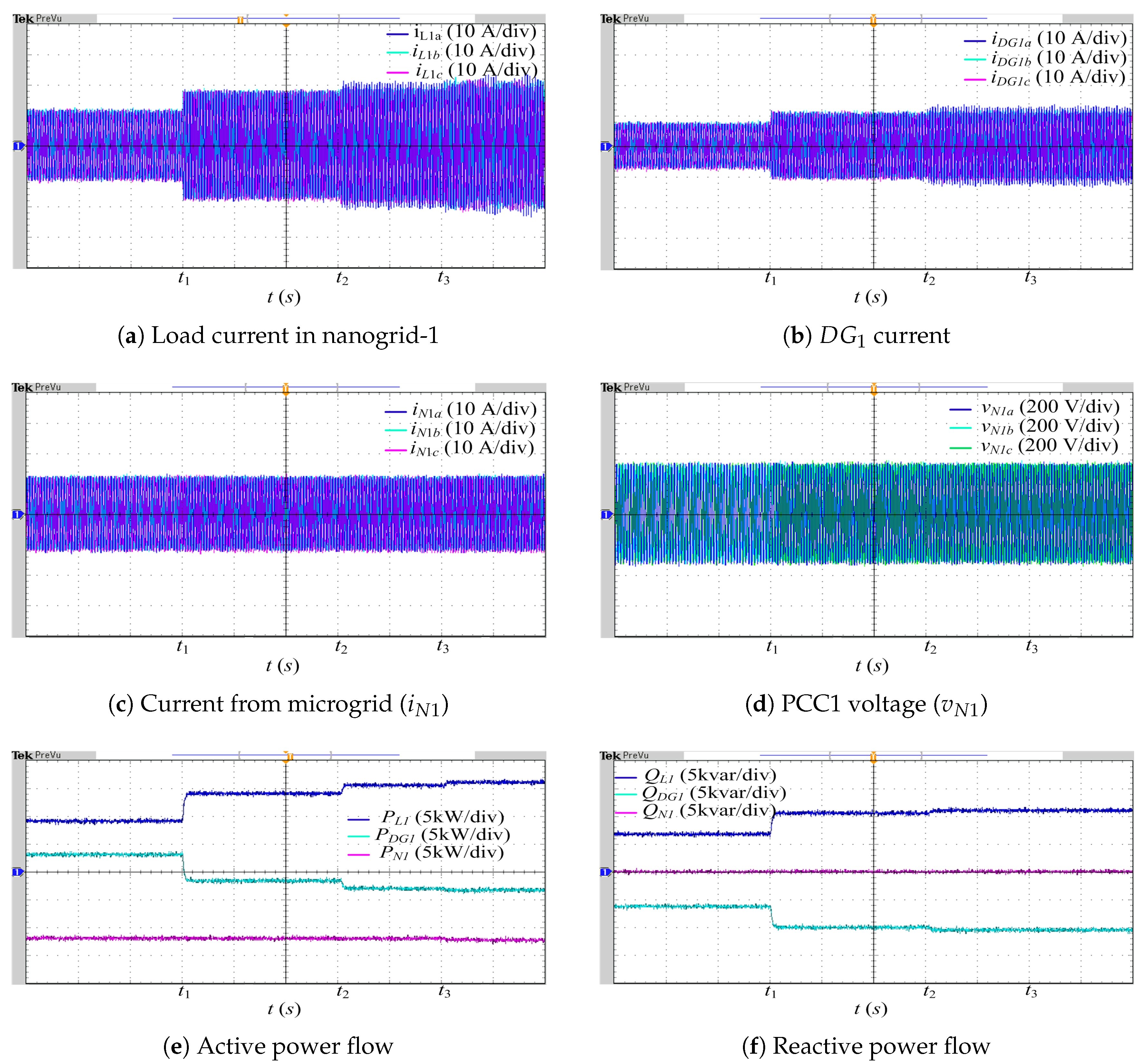
In grid connected operating mode of nanogrids, the respective DGs are controlled by using the proposed power control scheme. During this mode of operation, the nanogrids demand the constant active power from the microgrid. The constant power value is obtained from the estimation of average load demand in the nanogrid during grid connected operating mode. The average power demand in nanogrid-1, nanogrid-2 and nanogrid-3 during this operating mode are 12 kW, 8 kW and 6 kW respectively.
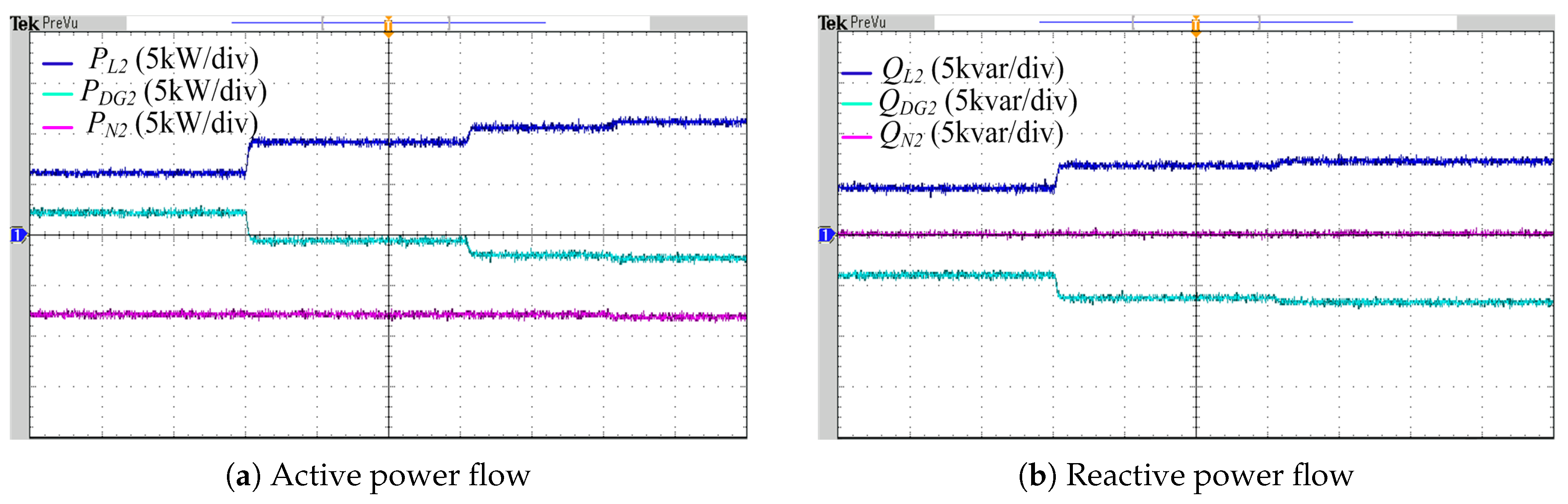
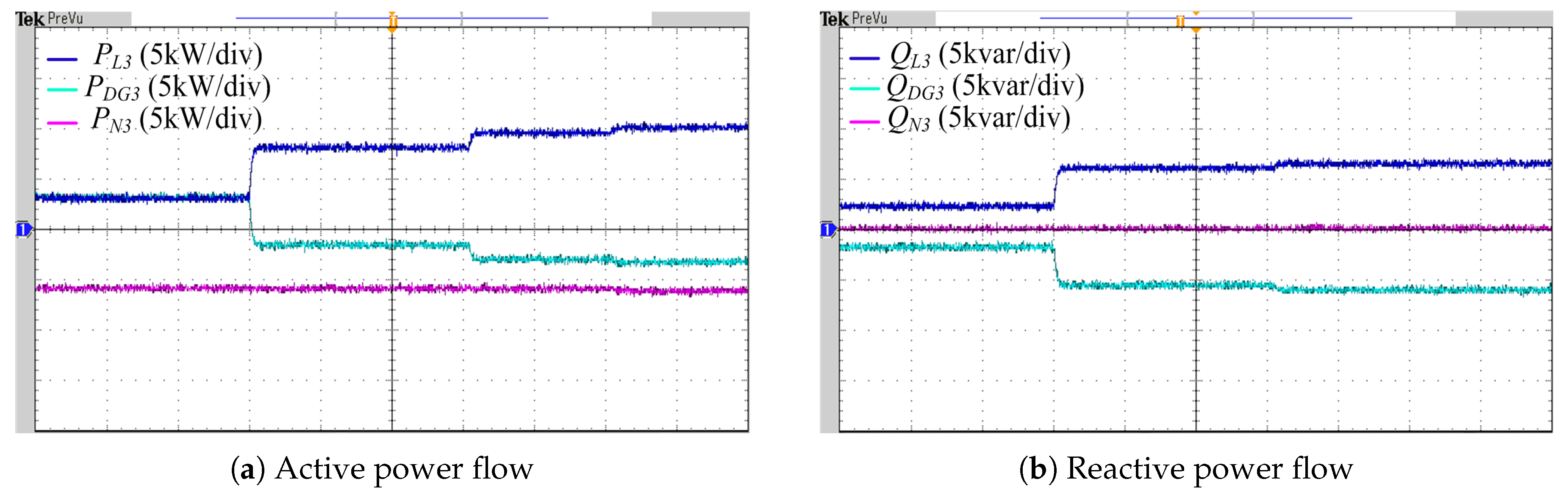
In nanogrid-1, initially the active power () load demand is 9 kW and the reactive power () demand 6.75 kvar as shown in Figure 6e,f, respectively. The corresponding three phase load currents (, and ) are represented in Figure 6a. The active power () demanded by nanogrid-1 from microgrid is 12 kW, the additional 3 kW active power is stored in local storage system of which is indicated as in Figure 6e. The demanded by the local loads in nanogrid-1 is compensated by the which is indicated as in Figure 6f. The three phase current supplied by and nanogrid-1 are represented as (, and ) and (, and ), respectively in Figure 6b. At instant in Figure 6a,e,f, the and demand in the nanogrid-1 is increased to 14 kW and 10.25 kvar. Even though, the load demand has changed in nanogrid-1; the and demand from the microgrid remains unchanged. Therefore, the deficit power of 2 kW is supplied by in the nanogrid-1 shown in Figure 6a–c,e. The is compensated by as shown in Figure 6f. At instant, the unbalanced load is connected in nanogrid-1 as shown in Figure 6a. The balanced is demanded from the microgrid irrespective of unbalance in . The total unbalance current is supplied by as shown in Figure 6b,c. At the instant, a non-linear load (650 resistive load with bridge rectifier) is connected to the system and the corresponding change in is observed in Figure 6a. The total harmonic currents demanded by the local loads in nanogrid-1 are compensated by and the corresponding currents ( and ) are shown in Figure 6a,b, respectively. Therefore, the local load variations, unbalanced load and nonlinear loads of nanogrid-1 will not affect the microgrid voltage (, and ) at PCC1 is shown in Figure 6d. The Figure 6 validates that a constant power demand by nanogrid-1 from microgrid is maintained irrespective of local load demand variation. Therefore, the bus voltage of microgrid remains unaffected under local load variations of nanogrid-1. In addition to this, the power quality of the microgrid is improved by compensating for unbalanced and harmonic currents demanded locally using respective local DG. The performance of and in nanogrid-2 and nanogrid-3 are similar to above, shown in Figure 7 and Figure 8 respectively.
4.2. Transition of Nanogrid Between Grid Connected and Islanded Operation Mode
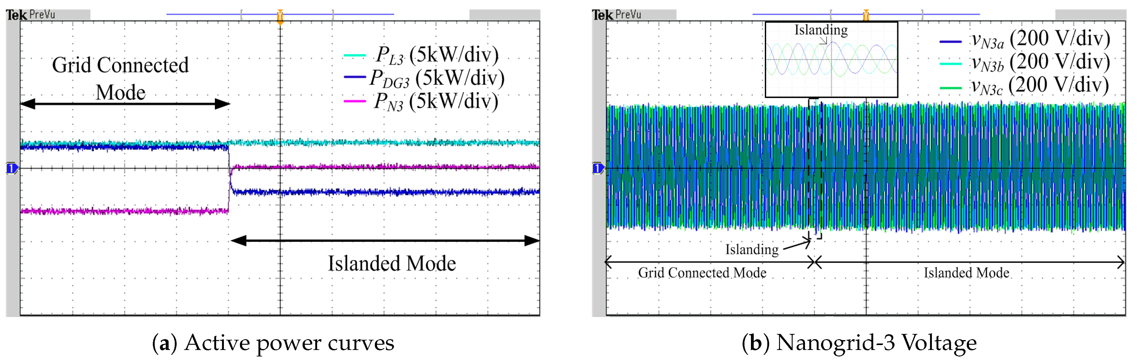
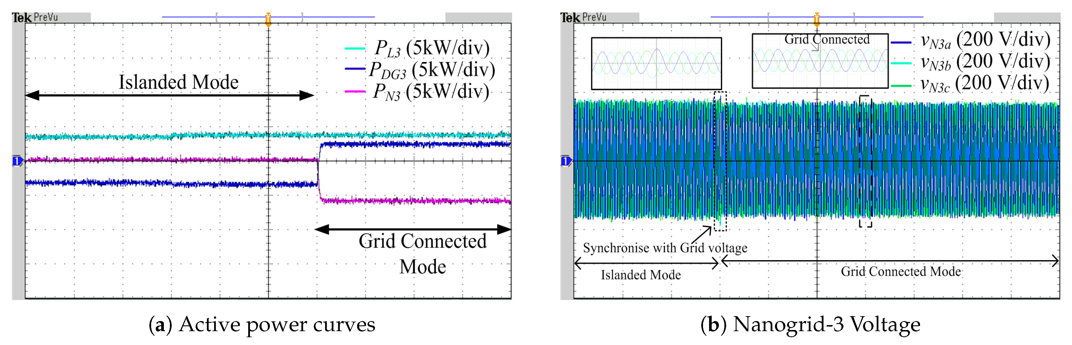
During healthy condition of microgrid, the nanogrids are interconnected with the microgrid. Initially, the load demand is shared by () and microgrid () as shown in Figure 9a. If a fault occurs in the microgrid, the nanogrids will be disconnected from the microgrid and operate in islanded mode. In this paper, the islanding is made intentionally to observe the transition of nanogrid between the two modes of operation. During the transition of the nanogrid to islanded mode, the controller of respective local DG is changed to modified voltage control technique and the voltage spike in the nanogrid () is controlled as shown in Figure 9b to achieve smooth transition. During islanded operation of nanogrid-3, the becomes zero and the is met with as shown in Figure 9a. When the microgrid is restored to a healthy condition, the nanogrid-3 will reconnect to the microgrid. However, before this reconnection; the nanogrid voltage is synchronised with the microgrid voltage by selecting the mode-2 shown in Figure 4. The seamless transition occurs during the reconnection of the nanogrid to the microgrid with the help of modified control technique, as shown in Figure 10.
4.3. Microgrid in Grid Connected Operation Mode
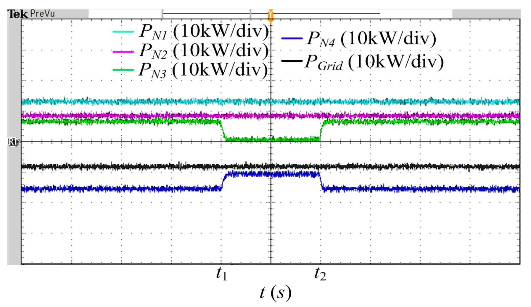
The active power demand by nanogrids in the microgrid are represented as , , and . is the active power supplied by main grid to the microgrid. During the grid connected operation mode of the microgrid, the DG in the nanogrids are controlled by proposed power control scheme. In Figure 6, Figure 7 and Figure 8, it is observed that the nanogrid load disturbances will not be reflected in the microgrid. Furthermore, the disturbances in the microgrid will not be reflected in the main grid with the help of the modified control scheme. During grid connected operating mode, the microgrid demands constant power from the main grid. This constant power value is estimated from the knowledge of additional average load demand by the microgrid during this operating mode. At instant in Figure 11, the nanogrid-3 is disconnected from the microgrid. Even though the power demand in the microgrid changes, constant power is demanded from the main grid shown in Figure 11. At instant, the nanogrid-3 is reconnected to the microgrid; however, the power demand by the microgrid from the main grid remains constant which is shown in Figure 11. Therefore, the main grid is unaffected by the disturbances occurring in the microgrid, which improves the stability of the main grid.
4.4. Microgrid Transition from Grid Connected to Islanded Operation Mode and Re-Synchronisation
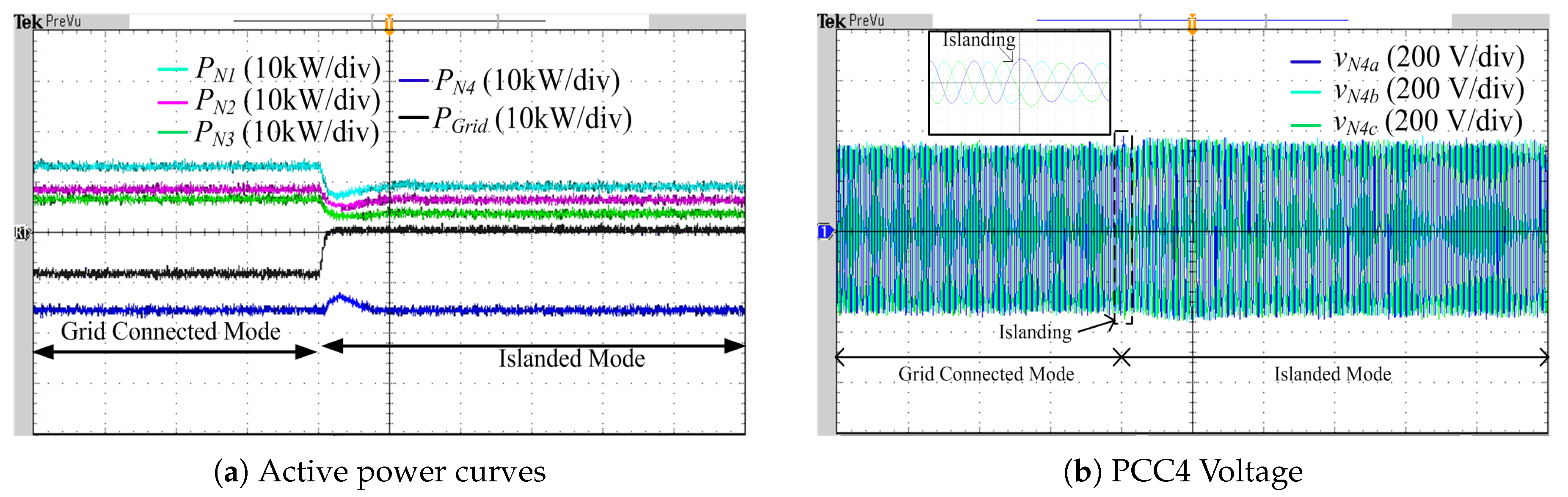
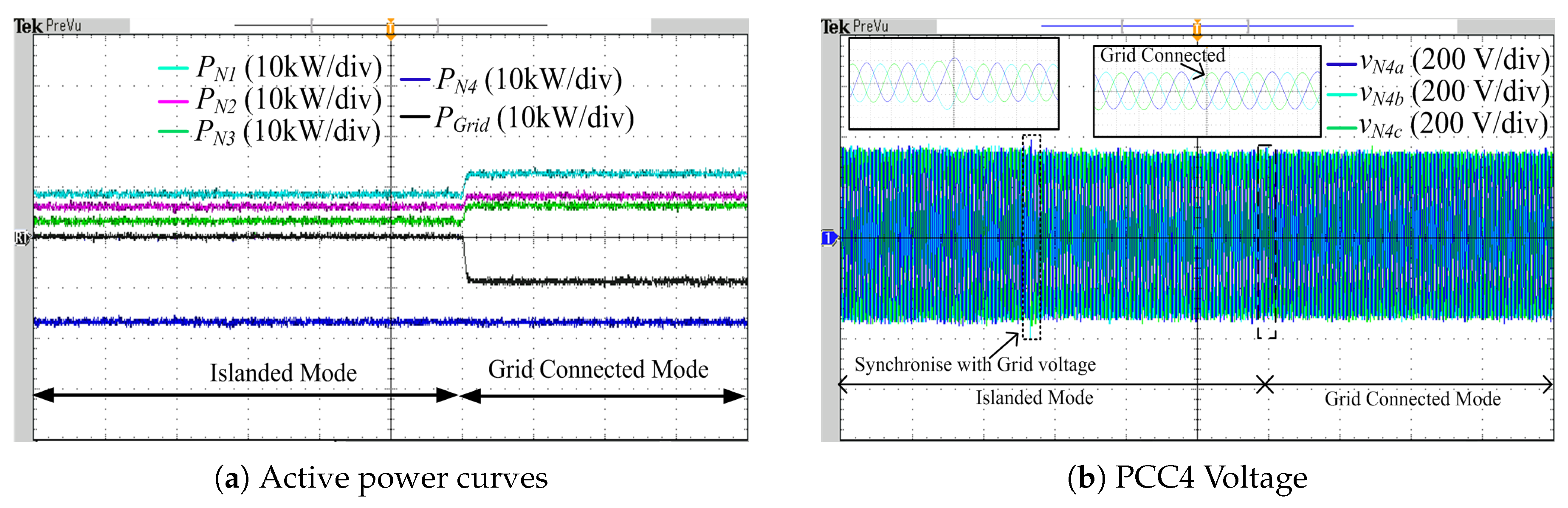
When the main grid is in a healthy condition, then the microgrid operates in grid connected mode. In this operating mode, DGs in the microgrid are controlled by the proposed power control scheme. If a fault occurs in main grid, then the microgrid will work in islanded mode by disconnecting from the main grid. To observe the transition of the microgrid between the two operating modes, an intentional islanding is done. During the transition of the microgrid to islanded mode, the controller of is changed to modified voltage control technique and the voltage spike in the microgrid () is controlled as shown in Figure 12b to achieve smooth transition. The power curves for the corresponding case are shown in Figure 12a. When the microgrid is restored to healthy condition, the microgrid will reconnect to the main grid. But, before this reconnection; the microgrid voltage is synchronised with the main grid voltage by selecting the mode-2 as shown in Figure 4. The modified control technique achieved seamless transition during the reconnection of the microgrid to the main grid, shown in Figure 13.
The proposed control scheme is compared with various other control schemes reported in the literature. The detailed comparison is given in Table 2.
5. Conclusions
The proposed control scheme is verified for dynamic performances under grid connected and islanded operating mode of the microgrid. The local DG in the nanogrids compensates for the unbalanced currents and reactive power locally; therefore, the microgrid voltage profile is maintained. The transient free operation of microgrid under load variations in the nanogrid is achieved by implementing the proposed modified control scheme. With this technique, smooth transition of the nanogrid between the grid connected and islanded operating modes are achieved. The overall microgrid acts as a constant load on main grid under various disturbances in the microgrid by using a modified control scheme for DGs; therefore, the microgrid is transient free from the disturbances. In addition, the smooth transition of the microgrid as well as the nanogrid between the operating modes (grid connected and islanded operating mode) are achieved. By implementing the proposed control scheme, the combined operation of various nanogrids with the main grid is achieved.
Author Contributions
G.G.T. and H.M.S. developed the concept: G.G.T. designed and tested in real time simulator: H.M.S. analyzed the data: G.G.T. and H.M.S. wrote the paper.
Funding
This research received no external funding.
Acknowledgments
This work was supported by the Department of Science and Technology, Government of India, Indo-U.K. collaborative project under Grant DST/RCUK/SEGES/2012/04.
Conflicts of Interest
The authors declare no conflict of interest.
References
- Shahidehpour, M.; Li, Z.; Gong, W.; Bahramirad, S.; Lopata, M. A Hybrid ac/dc Nanogrid: The Keating Hall Installation at the Illinois Institute of Technology. IEEE Electrif. Mag. 2017, 5, 36–46. [Google Scholar] [CrossRef]
- Liu, N.; Yu, X.; Fan, W.; Hu, C.; Rui, T.; Chen, Q.; Zhang, J. Online Energy Sharing for Nanogrid Clusters: A Lyapunov Optimization Approach. IEEE Trans. Smart Grid 2018, 9, 4624–4636. [Google Scholar] [CrossRef]
- Nasir, M.; Jin, Z.; Khan, H.A.; Zaffar, N.A.; Vasquez, J.C.; Guerrero, J.M. A Decentralized Control Architecture Applied to DC Nanogrid Clusters for Rural Electrification in Developing Regions. IEEE Trans. Power Electron. 2019, 34, 1773–1785. [Google Scholar] [CrossRef]
- Rocabert, J.; Luna, A.; Blaabjerg, F.; Rodríguez, P. Control of Power Converters in AC Microgrids. IEEE Trans. Power Electron. 2012, 27, 4734–4749. [Google Scholar] [CrossRef]
- Han, H.; Hou, X.; Yang, J.; Wu, J.; Su, M.; Guerrero, J.M. Review of Power Sharing Control Strategies for Islanding Operation of AC Microgrids. IEEE Trans. Smart Grid 2016, 7, 200–215. [Google Scholar] [CrossRef]
- Bollen, M.H.; Das, R.; Djokic, S.; Ciufo, P.; Meyer, J.; Rönnberg, S.K.; Zavodam, F. Power Quality Concerns in Implementing Smart Distribution-Grid Applications. IEEE Trans. Smart Grid 2017, 8, 391–399. [Google Scholar] [CrossRef]
- Chandorkar, M.C.; Divan, D.M.; Adapa, R. Control of parallel connected inverters in standalone AC supply systems. IEEE Trans. Ind. Appl. 1993, 29, 136–143. [Google Scholar] [CrossRef]
- Engler, A. Applicability of droops in low voltage grids. Int. J. Distrib. Energy Res. 2005, 1, 1–6. [Google Scholar]
- Guerrero, J.M.; Matas, J.; de Vicuna, L.G.; Castilla, M.; Miret, J. Wireless-Control Strategy for Parallel Operation of Distributed-Generation Inverters. IEEE Trans. Ind. Electron. 2006, 53, 1461–1470. [Google Scholar] [CrossRef]
- Trivedi, A.; Singh, M. L1 Adaptive Droop Control for AC Microgrid With Small Mesh Network. IEEE Trans. Ind. Electron. 2018, 65, 4781–4789. [Google Scholar] [CrossRef]
- Ziouani, I.; Boukhetala, D.; Darcherif, A.; Amghar, B.; el Abbassi, I. Hierarchical control for flexible microgrid based on three-phase voltage source inverters operated in parallel. Int. J. Electr. Power Energy Syst. 2018, 95, 188–201. [Google Scholar] [CrossRef]
- Kayalvizhi, S.; Kumar, D.M.V. Load Frequency Control of an Isolated Micro Grid Using Fuzzy Adaptive Model Predictive Control. IEEE Access 2017, 5, 16241–16251. [Google Scholar] [CrossRef]
- Han, Y.; Shen, P.; Zhao, X.; Guerrero, J.M. An Enhanced Power Sharing Scheme for Voltage Unbalance and Harmonics Compensation in an Islanded AC Microgrid. IEEE Trans. Energy Convers. 2012, 27, 831–841. [Google Scholar] [CrossRef]
- Vandoorn, T.; Meersman, B.; Kooning, J.D.; Vandevelde, L. Controllable harmonic current sharing in islanded microgrids: DG units with programmable resistive behavior toward harmonics. IEEE Trans. Power Deliv. 2012, 27, 831–841. [Google Scholar] [CrossRef]
- Trivedi, A.; Singh, M. Repetitive Controller for VSIs in Droop-Based AC-Microgrid. IEEE Trans. Power Electron. 2017, 32, 6595–6604. [Google Scholar] [CrossRef]
- Gholami, S.; Saha, S.; Aldeen, M. Robust multiobjective control method for power sharing among distributed energy resources in islanded microgrids with unbalanced and nonlinear loads. Int. J. Electr. Power Energy Syst. 2018, 94, 321–338. [Google Scholar] [CrossRef]
- Rezaei, M.M.; Soltani, J. A robust control strategy for a grid-connected multi-bus microgrid under unbalanced load conditions. Int. J. Electr. Power Energy Syst. 2015, 71, 68–76. [Google Scholar] [CrossRef]
- Kumar, S.; Singh, B. Seamless Operation and Control of Single Phase Hybrid PV-BES-Utility Synchronized System. IEEE Trans. Ind. Appl. 2019, 55, 1072–1082. [Google Scholar] [CrossRef]
- Tummuru, N.R.; Manandhar, U.; Ukil, A.; Gooi, H.B.; Kollimalla, S.K.; Naidu, S. Control strategy for AC-DC microgrid with hybrid energy storage under different operating modes. Int. J. Electr. Power Energy Syst. 2019, 104, 807–816. [Google Scholar] [CrossRef]
- Das, D.; Gurrala, G.; Shenoy, U.J. Linear Quadratic Regulator-Based Bumpless Transfer in Microgrids. IEEE Trans. Smart Grid 2018, 9, 416–425. [Google Scholar] [CrossRef]
- Arafat, M.N.; Elrayyah, A.; Sozer, Y. An Effective Smooth Transition Control Strategy Using Droop-Based Synchronization for Parallel Inverters. IEEE Trans. Ind. Appl. 2015, 51, 2443–2454. [Google Scholar] [CrossRef]
- Wang, J.; Chang, N.C.P.; Feng, X.; Monti, A. Design of a Generalized Control Algorithm for Parallel Inverters for Smooth Microgrid Transition Operation. IEEE Trans. Ind. Electron. 2015, 62, 4900–4914. [Google Scholar] [CrossRef]
- Caldognetto, T.; Tenti, P. Microgrids Operation Based on Master-Slave Cooperative Control. IEEE J. Emerg. Sel. Top. Power Electron. 2014, 2, 1081–1088. [Google Scholar] [CrossRef]
- Yang, J.; Yuan, W.; Sun, Y.; Han, H.; Hou, X.; Guerrero, J.M. A novel quasi-master-slave control frame for PV-storage independent microgrid. Int. J. Electr. Power Energy Syst. 2018, 97, 262–274. [Google Scholar] [CrossRef]
- Talapur, G.G.; Suryawanshi, H.M.; Xu, L.; Shitole, A.B. A Reliable Microgrid With Seamless Transition Between Grid Connected and Islanded Mode for Residential Community with Enhanced Power Quality. IEEE Trans. Ind. Appl. 2018, 54, 5246–5255. [Google Scholar] [CrossRef]
- Jain, P.; Agarwal, V.; Muni, B.P. Hybrid Phase Locked Loop for Controlling Master-Slave Configured Centralized Inverters in Large Solar Photovoltaic Power Plants. IEEE Trans. Ind. Appl. 2018, 54, 3566–3574. [Google Scholar] [CrossRef]
Figure 1.
Schematic of proposed microgrid for residential community.

Figure 2.
Schematic of voltage source converter (VSC) in distributed generations (DGs).

Figure 3.
Modified control scheme for DGs.

Figure 4.
Proposed modified voltage control for DG during islanded operating mode.

Figure 5.
Proposed Power Control Scheme for DG during grid connected operating mode.

Figure 6.
Current waveforms, PCC1 voltage and power flow curves in nanogrid-1.

Figure 7.
Power curves in Nanogrid-2.

Figure 8.
Power curves in Nanogrid-3.

Figure 9.
Transition of nanogrid-3 during grid connected to islanded operating mode.

Figure 10.
Transition of nanogrid-3 during islanded to grid connected operating mode.

Figure 11.
Microgrid active power curves.

Figure 12.
Transition of microgrid during grid connected to islanded operating mode.

Figure 13.
Transition of microgrid during islanded to grid connected operation mode.


Table 1.
The Microgrid Parameters.
| Sr.No. | Parameter | Value |
|---|---|---|
| 1 | Microgrid Voltage | 415 V (L-L) |
| 1 | Microgrid Frequency | 50 Hz |
| 2 | Rating of | 30 kVA |
| 3 | Rating of | 25 kVA |
| 4 | Rating of | 20 kVA |
| 5 | Rating of | 50 kVA |
| 6 | Line Impedance | 3 mH, 1.334 |
| 7 | Filter | 0.15 , 6 mH and 50 F |
| 8 | DC link Voltage of DGs | 760 V |
| 9 | Switching Frequency of VSC | 3150 Hz |
Table 2.
Comparative analysis of proposed control scheme.
| Criteria | [13] | [18] | [20] | [23] | [24] | Proposed |
|---|---|---|---|---|---|---|
| Voltage regulation | yes | yes | yes | yes | yes | yes |
| Compensation of reactive power, harmonics and unbalanced current | yes | yes | - | yes | Yes | yes |
| Seamless transition between modes of operation | - | yes | yes | - | - | yes |
| Dynamics during disturbances (on voltage source) | medium | poor | medium | poor | poor | good |
| Control complexity | more | medium | medium | medium | medium | less |
© 2019 by the authors. Licensee MDPI, Basel, Switzerland. This article is an open access article distributed under the terms and conditions of the Creative Commons Attribution (CC BY) license (http://creativecommons.org/licenses/by/4.0/).
Share and Cite
MDPI and ACS Style
Talapur, G.G.; Suryawanshi, H.M. A Modified Control Scheme for Power Management in an AC Microgrid with Integration of Multiple Nanogrids. Electronics 2019, 8, 490. https://0-doi-org.brum.beds.ac.uk/10.3390/electronics8050490
AMA Style
Talapur GG, Suryawanshi HM. A Modified Control Scheme for Power Management in an AC Microgrid with Integration of Multiple Nanogrids. Electronics. 2019; 8(5):490. https://0-doi-org.brum.beds.ac.uk/10.3390/electronics8050490
Chicago/Turabian StyleTalapur, Girish G., and Hiralal M. Suryawanshi. 2019. "A Modified Control Scheme for Power Management in an AC Microgrid with Integration of Multiple Nanogrids" Electronics 8, no. 5: 490. https://0-doi-org.brum.beds.ac.uk/10.3390/electronics8050490
Note that from the first issue of 2016, this journal uses article numbers instead of page numbers. See further details here.