Mobile-Phone Antenna Array with Diamond-Ring Slot Elements for 5G Massive MIMO Systems

 ,
,  ,
,  ,
,  ,
,  and
and 
Abstract
:1. Introduction
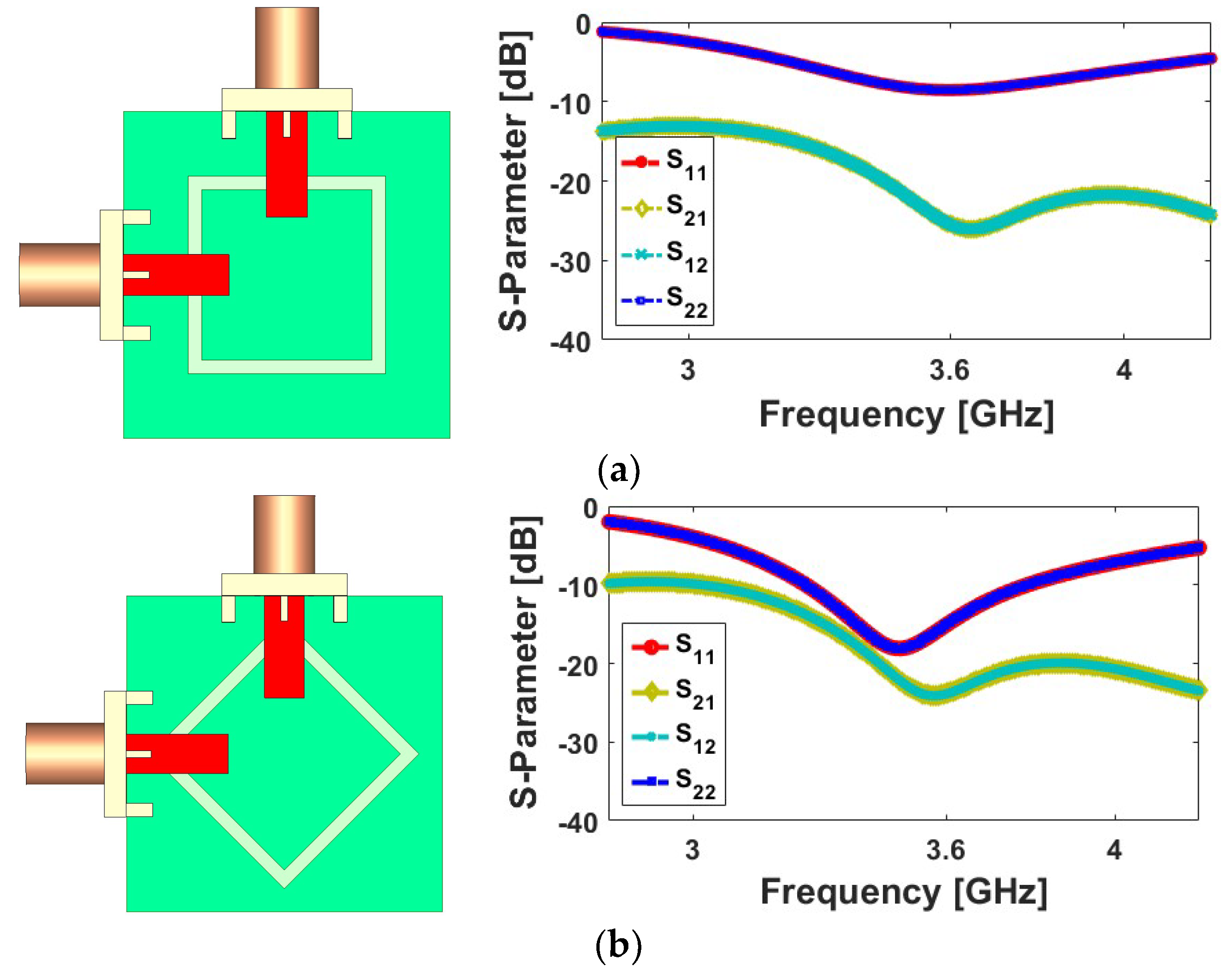
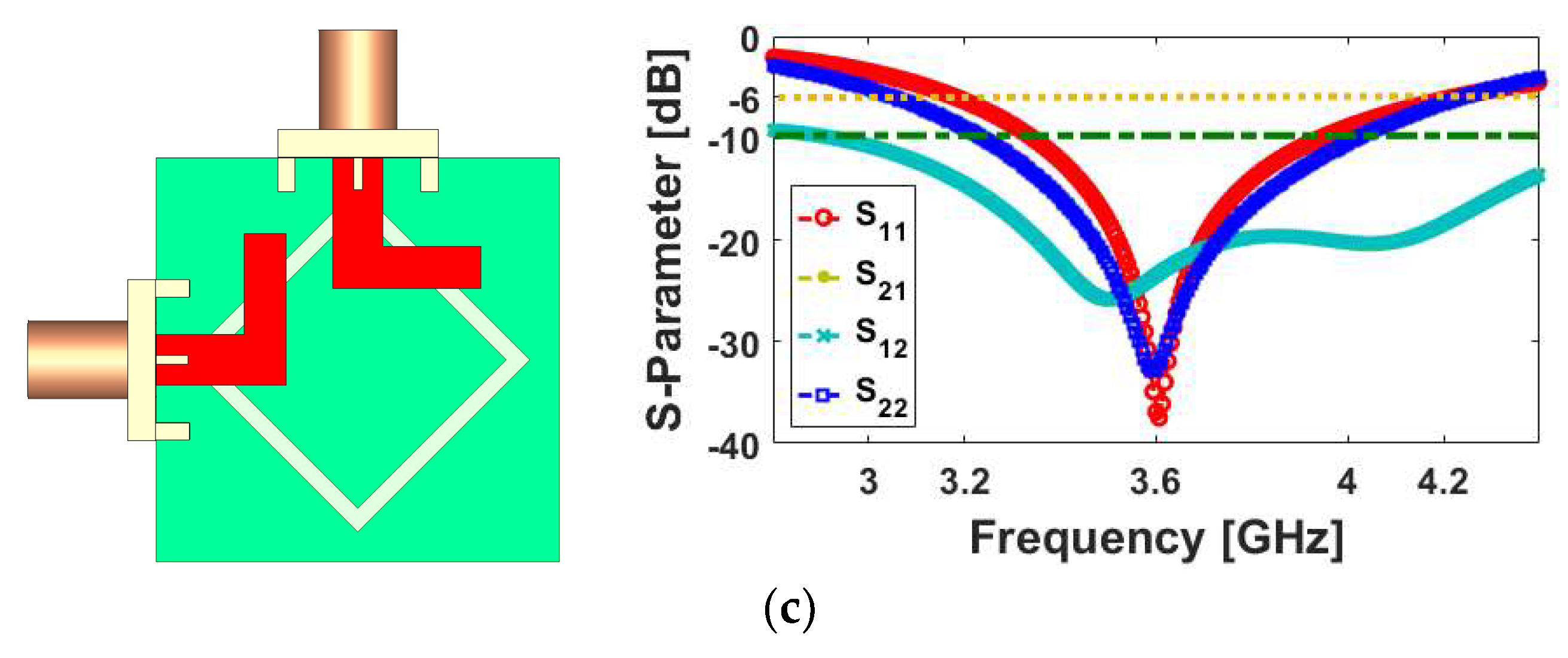
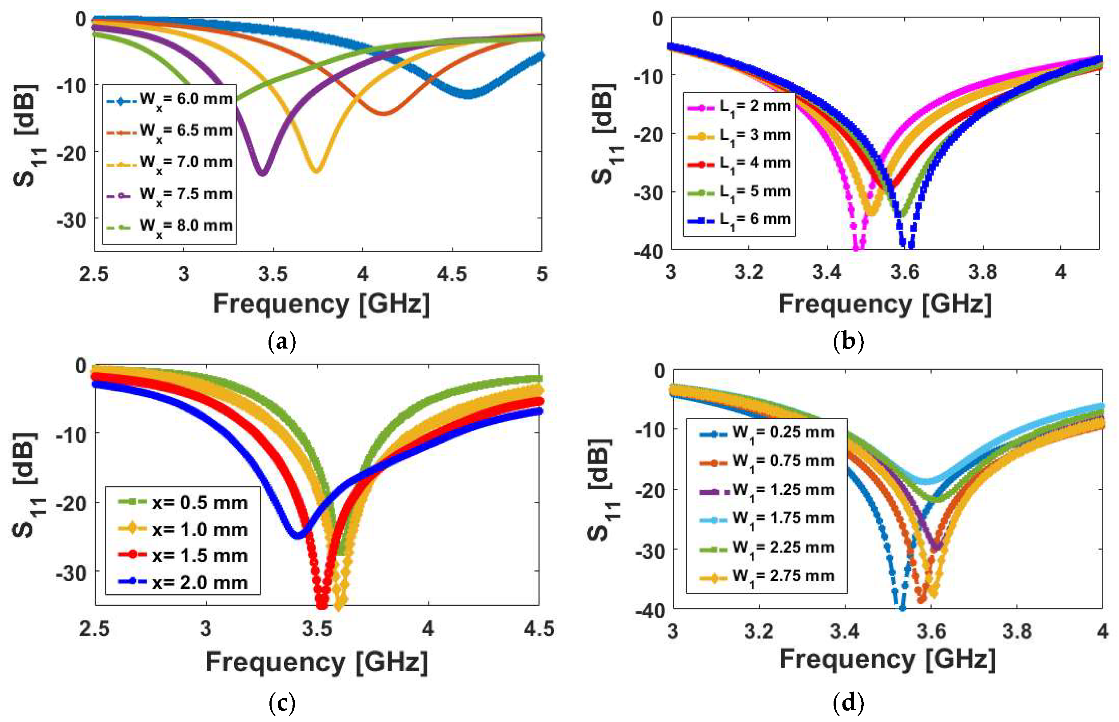
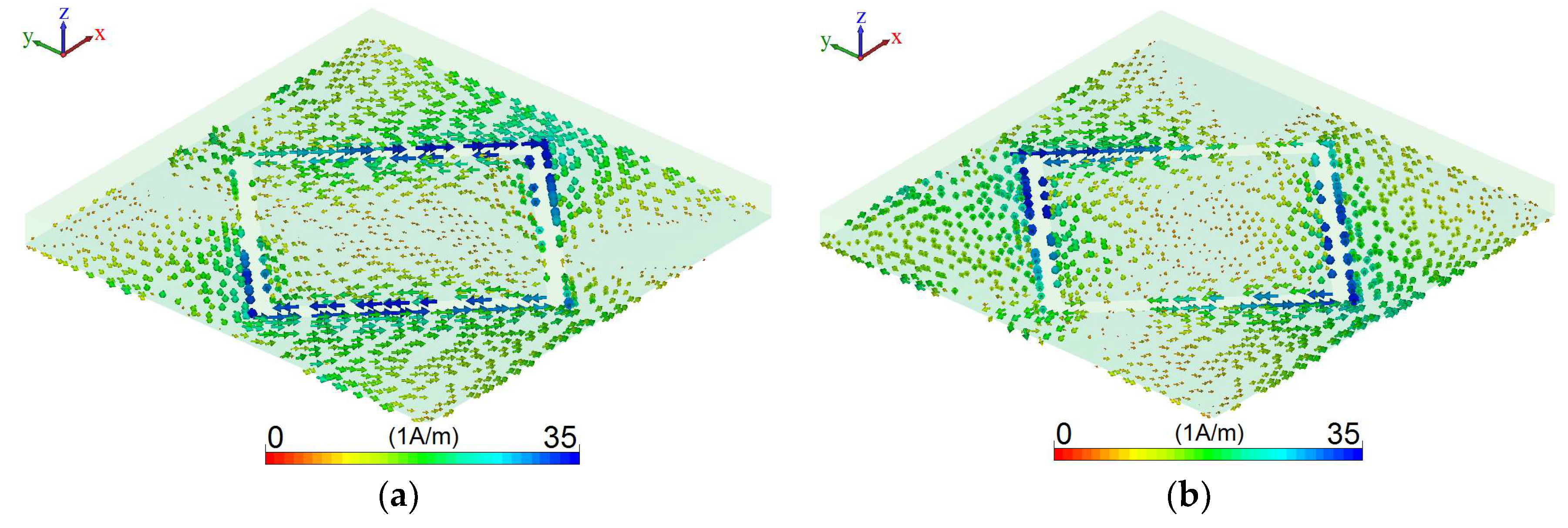
2. Single-Element Diamond-Ring Slot Antenna
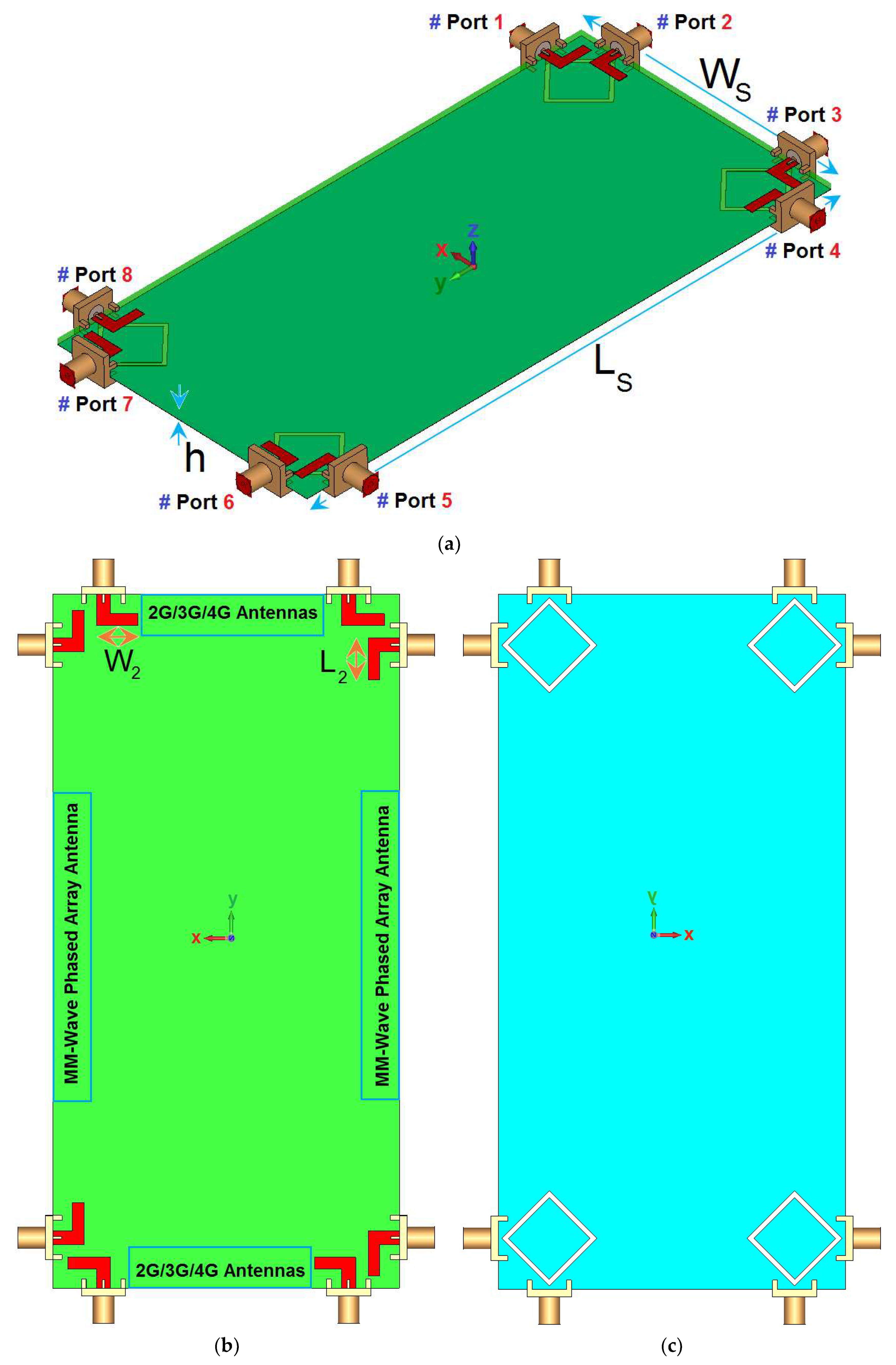
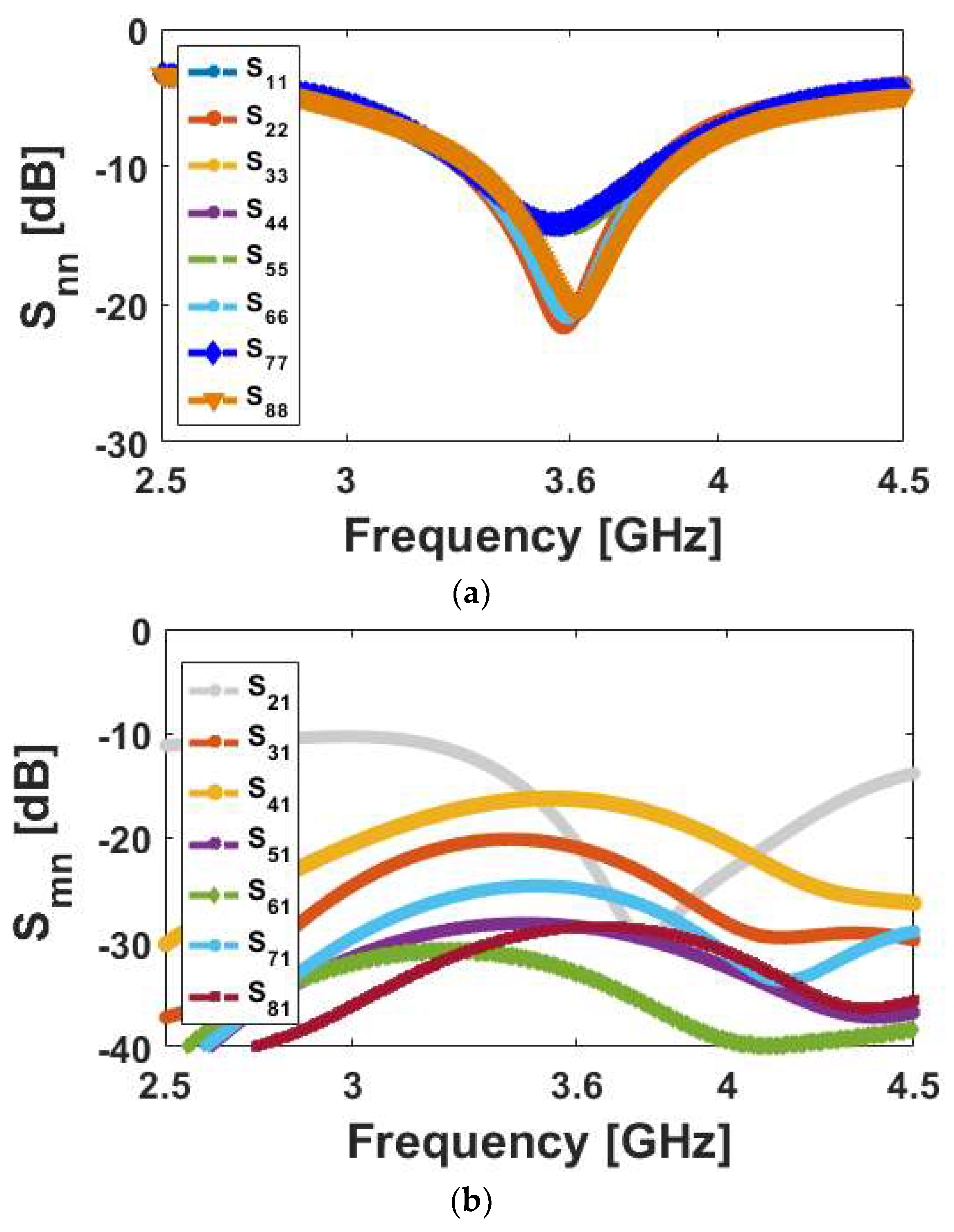
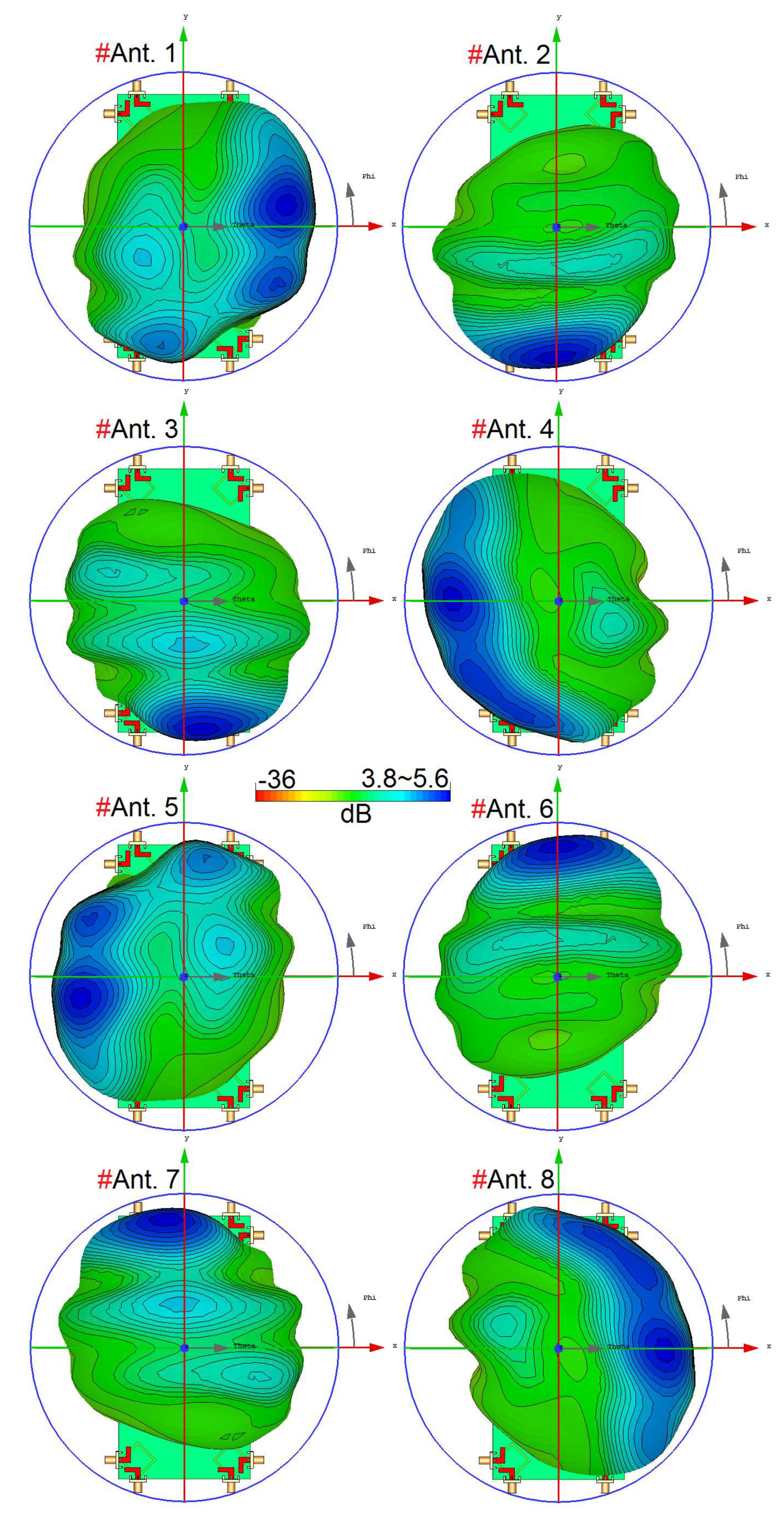
3. Mobile-Phone Antenna Design
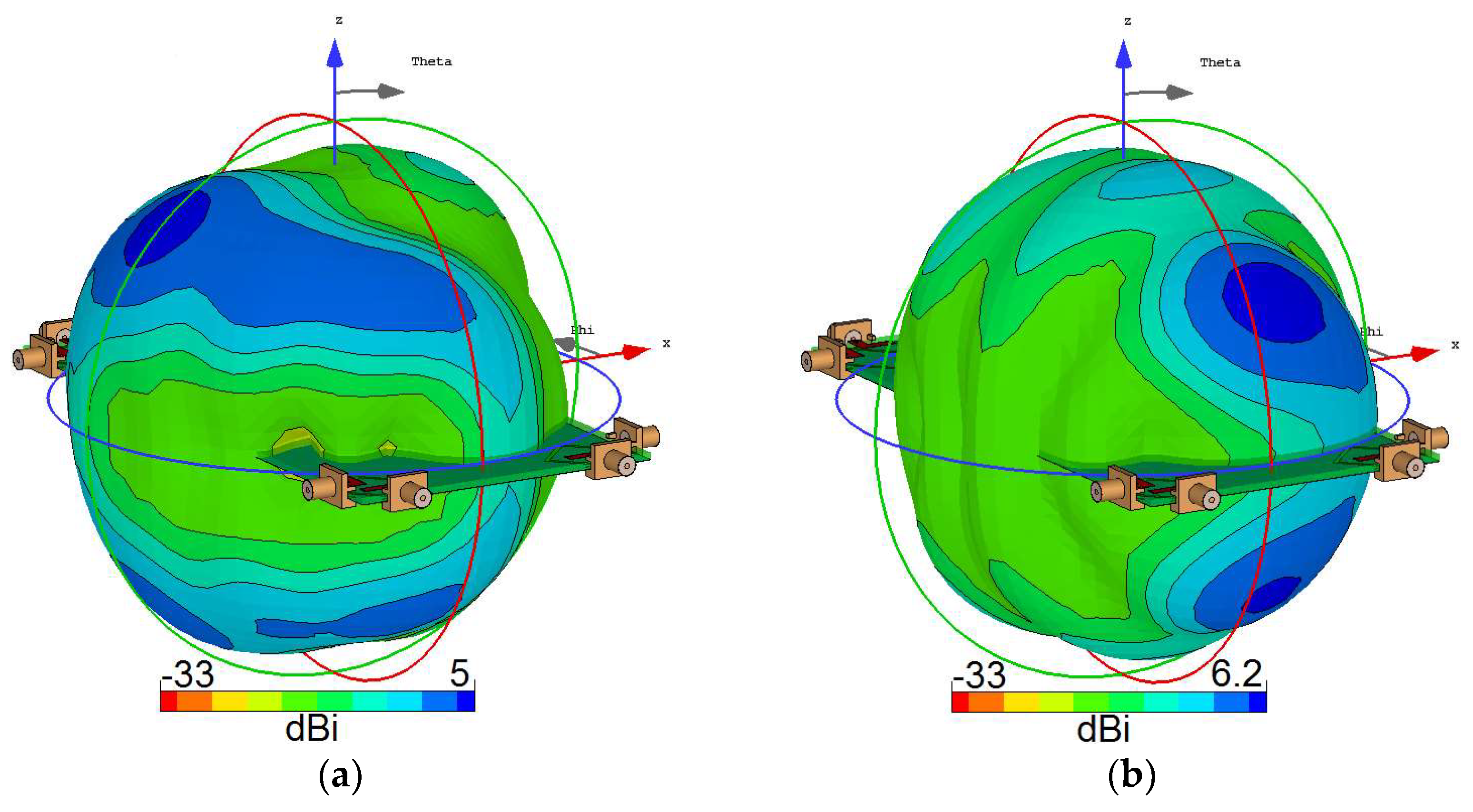
4. User-Hand/User-Head Impacts on the Mobile-Phone Antenna Performance
5. Conclusions
Author Contributions
Funding
Acknowledgments
Conflicts of Interest
References
- Jensen, M.; Wallace, J. A review of antennas and propagation for MIMO wireless communications. IEEE Trans. Antennas Propag. 2004, 52, 2810–2824. [Google Scholar] [CrossRef]
- Gesbert, D.; Shafi, M.; Shiu, D.S.; Smith, P.J.; Naguib, A. From theory to practice: An overview of MIMO space-time coded wireless systems. IEEE J. Sel. Areas Commun. 2003, 21, 281–302. [Google Scholar] [CrossRef]
- Votis, C.; Christofilakis, V.; Raptis, V.; Tatsis, G.; Chronopoulos, S.K.; Kostarakis, P. Design and analysis of a multiple-output transmitter based on DDS architecture for modern wireless communications. AIP Conf. Proc. 2010, 1203, 421–426. [Google Scholar]
- Kammoun, A.; Debbah, M.; Alouini, M.S. Design of 5G full dimension massive MIMO systems. IEEE Trans. Commun. 2018, 66, 726–740. [Google Scholar]
- Osseiran, A.; Boccardi, F.; Braun, V.; Kusume, K.; Marsch, P.; Maternia, M.; Queseth, O.; Schellmann, M.; Schotten, H.; Taoka, H.; et al. Scenarios for 5G mobile and wireless communications: The vision of the METIS project. IEEE Commun. Mag. 2014, 52, 26–35. [Google Scholar] [CrossRef]
- Angelis, C.T.; Chronopoulos, S.K. System performance of an LTE MIMO downlink in various fading environments. In Proceedings of the Ambient Media and Systems, Berlin, Germany, 27–28 January 2011; pp. 36–43. [Google Scholar]
- Ojaroudiparchin, N.; Shen, M.; Pedersen, G.F. Multi-layer 5G mobile phone antenna for multi-user MIMO communications. In Proceedings of the 23rd Telecommunications Forum (TELFOR), Belgrade, Serbia, 24–26 November 2015; pp. 559–562. [Google Scholar]
- Hassan, N.; Fernando, X. Massive MIMO Wireless Networks: An Overview. Electronics 2017, 6, 63. [Google Scholar] [CrossRef]
- Larsson, E.; Edfors, O.; Tufvesson, F.; Marzetta, T. Massive MIMO for next generation wireless Systems. IEEE Commun. Mag. 2014, 52, 186–195. [Google Scholar] [CrossRef]
- Yang, H.H.; Quek, T.Q.S. Massive MIMO Meet Small Cell; Springer Briefs in Electrical and Computer Engineering; Springer International Publishing: Basel, Switzerland, 2017. [Google Scholar]
- Sharawi, M.S. Printed MIMO Antenna Engineering; Artech House: Norwood, MA, USA, 2014. [Google Scholar]
- Parchin, N.O.; Basherlou, H.J.; Al-Yasir, Y.I.A.; Abd-Alhameed, R.A.; Abdulkhaleq, A.M.; Noras, J.M. Recent developments of reconfigurable antennas for current and future wireless communication systems. Electronics 2019, 8, 128. [Google Scholar] [CrossRef]
- Parchin, N.O.; Al-Yasir, Y.; Abdulkhaleq, A.M.; Elfergani, I.; Rayit, A.; Noras, J.M.; Rodriguez, J.; Abd-Alhameed, R.A. Frequency reconfigurable antenna array for mm-Wave 5G mobile handsets. In Proceedings of the 9th International Conference on Broadband Communications, Networks, and Systems, Faro, Portugal, 19–20 September 2018. [Google Scholar]
- Al-Yasir, Y.; Abdullah, A.; Ojaroudi Parchin, N.; Abd-Alhameed, R.; Noras, J. A new polarization-reconfigurable antenna for 5G applications. Electronics 2018, 7, 293. [Google Scholar] [CrossRef]
- Hussain, R.; Alreshaid, A.T.; Podilchak, S.K.; Sharawi, M.S. Compact 4G MIMO antenna integrated with a 5G array for current and future mobile handsets. IET Microw. Antennas Propag. 2017, 11, 271–279. [Google Scholar] [CrossRef]
- Chen, Q.; Lin, H.; Wang, J.; Ge, L.; Li, Y.; Pei, T. Single ring slot based antennas for metal-rimmed 4G/5G smartphones. IEEE Trans. Antennas Propag. 2019, 67, 1476–1487. [Google Scholar] [CrossRef]
- Ojaroudi Parchin, N.; Abd-Alhameed, R.A. A compact Vivaldi antenna array for 5G channel sounding applications. In Proceedings of the 12th European Conference on Antennas and Propagation, London, UK, 9–13 April 2018. [Google Scholar]
- Al-Hadi, A.A.; Ilvonen, J.; Valkonen, R.; Viikan, V. Eight-element antenna array for diversity and MIMO mobile terminal in LTE 3500MHz band. Microw. Opt. Technol. Lett. 2014, 56, 1323–1327. [Google Scholar] [CrossRef]
- Abdullah, M. Compact 4-Port MIMO antenna system for 5G mobile terminal. In Proceedings of the International Applied Computational Electromagnetics Society Symposium, Florence, Italy, 26–30 March 2017. [Google Scholar]
- Ojaroudi Parchin, N.; Al-Yasir, Y.I.A.; Abd-Alhameed, R.A.; Noras, J.M. Dual-polarized MIMO antenna array design using miniaturized self-complementary structures for 5G smartphone applications. In Proceedings of the EuCAP Conference, Krakow, Poland, 31 March–5 April 2019. accepted. [Google Scholar]
- Wong, K.L.; Lu, J.Y.; Chen, L.Y.; Li, W.Y.; Ban, Y.L. 8-antenna and 16-antenna arrays using the quad-antenna linear array as a building block for the 3.5-GHz LTE MIMO operation in the smartphone. Microw. Opt. Technol. Lett. 2016, 58, 174–181. [Google Scholar] [CrossRef]
- Rao, L.-Y.; Tsai, C.-J. 8-loop antenna array in the 5 inches size smartphone for 5G communication the 3.4 GHz–3.6 GHz band MIMO operation. In Proceedings of the Progress in Electromagnetics Research Symposium (PIERS), Toyama, Japan, 1–4 August 2018. [Google Scholar]
- Abdullah, M.; Ban, Y.L.; Kang, K.; Li, M.Y.; Amin, M. Eight-element antenna array at 3.5GHz for MIMO wireless application. Prog. Electromagn. Res. C 2017, 78, 209–217. [Google Scholar] [CrossRef]
- Li, Y.; Luo, Y.; Yang, G. High-isolation 3.5-GHz 8-antenna MIMO array using balanced open slot antenna element for 5G smartphones. IEEE Trans. Antennas Propag. 2019. [Google Scholar] [CrossRef]
- Sun, L.; Feng, H.; Li, Y.; Zhang, Z. Compact 5G MIMO mobile phone antennas with tightly arranged orthogonal-mode pairs. IEEE Trans. Antennas Propag. 2018, 66, 6364–6369. [Google Scholar] [CrossRef]
- Li, M.Y.; Ban, Y.L.; Xu, Z.Q.; Guo, J.; Yu, Z.F. Tri-polarized 12-antenna MIMO array for future 5G smartphone applications. IEEE Access 2018, 6, 6160–6170. [Google Scholar] [CrossRef]
- Zhao, A.; Ren, Z. Size reduction of self-isolated MIMO antenna system for 5G mobile phone applications. IEEE Antennas Wirel. Propag. Lett. 2019, 18, 152–156. [Google Scholar] [CrossRef]
- Statement: Improving Consumer Access to Mobile Services at 3.6 GHz to 3.8 GHz. Available online: https://www.ofcom.org.uk/consultations-and-statements/category-1/future-use-at-3.6-3.8-ghz (accessed on 21 October 2018).
- CST Microwave Studio; ver. 2018; CST: Framingham, MA, USA, 2018.
- Chang, K. Microwave Ring Circuits and Antennas; Wiley: New York, NY, USA, 1996. [Google Scholar]
- Batchelor, J.C.; Langley, R.J. Microstrip annular ring slot antennas for mobile applications. Electron. Lett. 2019, 32, 1635–1636. [Google Scholar] [CrossRef]
- Yoshimura, Y. A microstripline slot antenna. IEEE Trans. Microw. Theory Tech. 1972, 20, 760–762. [Google Scholar] [CrossRef]
- Elfergani, I.; Hussaini, A.S.; Rodriguez, J.; Abd-Alhameed, R. Antenna Fundamentals for Legacy Mobile Applications and Beyond; Springer Nature: Basingstoke, UK, 2017; pp. 1–659. [Google Scholar]
- Al-Nuaimi, M.K.T.; Whittow, W.G. Performance investigation of a dual element IFA array at 3 GHz for MIMO terminals. In Proceedings of the Antennas and Propagation Conference (LAPC), Loughborough, UK, 14–15 November 2011; pp. 1–5. [Google Scholar]
- Nguyen, Q.D.; Le, T.T.; Le, D.T.; Tran, X.N.; Yamada, Y. A compact MIMO ultra-wide band antenna with low mutual coupling. Appl. Comput. Electromagn. Soc. J. 2018, 31, 252–260. [Google Scholar]
- Parchin, N.O.; Al-Yasir, Y.I.; Ali, A.H.; Elfergani, I.; Noras, J.M.; Rodriguez, J.; Abd-Alhameed, R.A. Eight-element dual-polarized MIMO slot antenna system for 5G smartphone applications. IEEE Access 2019, 9, 15612–15622. [Google Scholar] [CrossRef]
- Syrytsin, I.; Zhang, S.; Pedersen, G.F. Performance investigation of a mobile terminal phased array with user effects at 3.5 GHz for LTE advanced. IEEE Antennas Wirel. Propag. Lett. 2017, 16, 1847–1850. [Google Scholar] [CrossRef]
- Sharawi, M.S. Printed multi-band MIMO antenna systems and their performance metrics [wireless corner]. IEEE Antennas Propag. Mag. 2013, 55, 218–232. [Google Scholar] [CrossRef]
- Ojaroudi Parchin, N.; Alibakhshikenari, M.; Jahanbakhsh Basherlou, H.; AAbd-Alhameed, R.; Rodriguez, J.; Limiti, E. mm-Wave phased array quasi-Yagi antenna for the upcoming 5G cellular communications. Appl. Sci. 2019, 9, 978. [Google Scholar] [CrossRef]
- Basar, M.R.; Malek, M.F.; Juni, K.M.; Saleh, M.I.; Idris, M.S.; Mohamed, L.; Saudin, N.; Mohd Affendi, N.A.; Ali, A. The use of a human body model to determine the variation of path losses in the human body channel in wireless capsule endoscopy. Prog. Electromagn. Res. 2013, 133, 495–513. [Google Scholar] [CrossRef]


| Parameter | Value (mm) | Parameter | Value (mm) | Parameter | Value (mm) | Parameter | Value (mm) |
|---|---|---|---|---|---|---|---|
| WS | 75 | LS | 150 | x | 1 | W | 24 |
| L | 24 | Wf | 3 | Lf | 5.25 | W1 | 2.5 |
| L1 | 3.9 | W2 | 8.9 | L2 | 9.9 | Wx | 7.25 |
| Reference | Bandwidth (GHz) | Efficiency (%) | Size (mm2) | Isolation (dB) | ECC |
|---|---|---|---|---|---|
| [18] | 3.4–3.6 | 55–60 | 100 × 50 | 10 | - |
| [19] | 3.4–3.6 | - | 136 × 68 | 15 | - |
| [20] | 3.55–3.65 | 52–76 | 150 × 75 | 11 | - |
| [21] | 3.4–3.6 | 35–50 | 150 × 75 | 11 | <0.40 |
| [22] | 3.4–3.6 | 30–50 | 145 × 70 | 15 | <0.2 |
| [23] | 3.4–3.6 | 40–60 | 136 × 68 | 14 | <0.2 |
| [24] | 3.4–3.6 | 60–75 | 150 × 80 | 17 | <0.05 |
| [25] | 3.4–3.6 | 50–70 | 150× 73 | 17 | <0.07 |
| [26] | 3.4–3.6 | 50–80 | 150 × 75 | 15 | <0.2 |
| [27] | 3.4–3.6 | 60–70 | 150 × 75 | 18 | <0.015 |
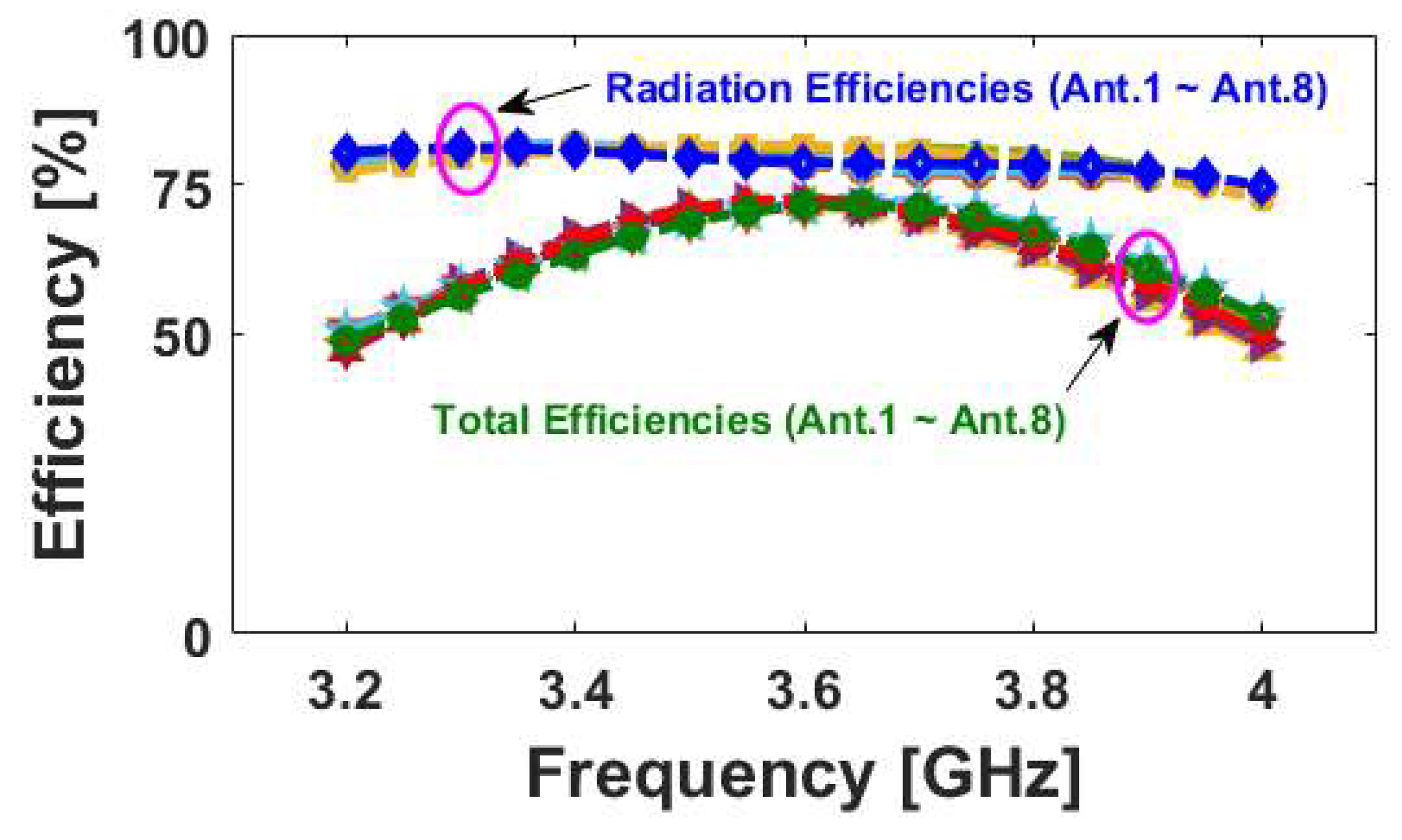
| Proposed | 3.3–3.9 | 60–80 | 150 × 75 | 17 | <0.01 |
© 2019 by the authors. Licensee MDPI, Basel, Switzerland. This article is an open access article distributed under the terms and conditions of the Creative Commons Attribution (CC BY) license (http://creativecommons.org/licenses/by/4.0/).
Share and Cite
Ojaroudi Parchin, N.; Jahanbakhsh Basherlou, H.; Alibakhshikenari, M.; Ojaroudi Parchin, Y.; Al-Yasir, Y.I.A.; Abd-Alhameed, R.A.; Limiti, E. Mobile-Phone Antenna Array with Diamond-Ring Slot Elements for 5G Massive MIMO Systems. Electronics 2019, 8, 521. https://0-doi-org.brum.beds.ac.uk/10.3390/electronics8050521
Ojaroudi Parchin N, Jahanbakhsh Basherlou H, Alibakhshikenari M, Ojaroudi Parchin Y, Al-Yasir YIA, Abd-Alhameed RA, Limiti E. Mobile-Phone Antenna Array with Diamond-Ring Slot Elements for 5G Massive MIMO Systems. Electronics. 2019; 8(5):521. https://0-doi-org.brum.beds.ac.uk/10.3390/electronics8050521
Chicago/Turabian StyleOjaroudi Parchin, Naser, Haleh Jahanbakhsh Basherlou, Mohammad Alibakhshikenari, Yasser Ojaroudi Parchin, Yasir I. A. Al-Yasir, Raed A. Abd-Alhameed, and Ernesto Limiti. 2019. "Mobile-Phone Antenna Array with Diamond-Ring Slot Elements for 5G Massive MIMO Systems" Electronics 8, no. 5: 521. https://0-doi-org.brum.beds.ac.uk/10.3390/electronics8050521