1. Introduction
Centralized power plants no longer have a monopoly on energy generation, which is becoming more and more distributed, especially with the evolution of distributed renewable energy resources and storage systems. Indeed, in the new microgrid paradigm, there is no differentiation between energy producers and consumers anymore, as they are both considered as a unique entity that can be referred to as “prosumer” [
1]. These energy prosumers are responsible for producing and ensuring their needs for power. Moreover, they are encouraged to share their energy production and control the power flow between them. For these reasons, the scientific community is giving great importance to research in the area of modeling and control of microgrids [
2].
To allow parallel operations of multiple distributed generation units (DGUs) and load sharing in islanded microgrids, different control methods have been proposed in the literature. These control schemes can be categorized into two main groups depending on the use of communication technology. The first category includes the active load sharing methods such as centralized [
3], master–slave [
4], and average load sharing [
5], which ensure accurate load sharing and proper voltage regulation; however, they present a single point of failure since they rely on communication infrastructure for power measurements and coordination between the DGUs. The second category covers the communication-free schemes, mainly the droop characteristic methods, that use only local measurements to share the load and maintain the voltage [
6].
Droop control in DC microgrids consists of simply implementing a virtual resistive impedance between the DGU and the point of common coupling to allow the sharing of the load current according to the droop settings [
7,
8]. For AC microgrids, droop control mimics the behavior of the conventional electrical grid with synchronous generators. Particularly, the relationships between frequency and real power
and between voltage magnitude and reactive power
, which govern the spinning machines, are used to share both active and reactive power between the generators. This is achieved by changing the frequency (voltage magnitude) setpoint of the DGUs when the active (reactive) power balance is altered [
9].
The conventional
droop control assumes that the impedance of the lines is predominantly inductive [
10]. However, this assumption is valid only in high-voltage microgrids with geographically dispersed DGUs, whereas for low voltage AC microgrids, the lines are mainly resistive and the ratio
is greater, which makes the coupling of active and reactive power more significant. To overcome this issue, the droop control characteristics need to be modified. The authors of [
11] propose a modified active and reactive power
and
to achieve accurate power-sharing in low-voltage microgrids. However, this method is not suitable for large microgrids. A hybrid control architecture was presented in [
12], where a modified droop control shares power between blocks of inverters and a dynamic power distribution scheme shares the power among the inverters of the same block. Again, the proposed method is only applicable for low-voltage microgrids. A more recent study [
13] suggests that the conventional
droop control can still be used for the low voltage converter-based AC microgrids and gives satisfactory results. However, frequency regulations limit the frequency droop gain and require a secondary control with slower loops to correct the frequency deviation and restore it to the nominal value, as it is not desirable for the microgrid to operate at a frequency lower than the nominal value [
14].
Angle droop control has been proposed in [
14,
15] to achieve power-sharing without changing the frequency of the microgrid. However, this method has several drawbacks since it relies on accurate voltage angle measurement with respect to a reference angle. Also, it requires high values of angle droop gains to guarantee proper load sharing, which may cause instability of the overall system. In [
16], the authors propose a supplementary angle droop control loop to improve the stability even with large droop gains, but the design of the additional droop control loop is relatively complicated.
The authors of [
17] present a dq voltage droop control for equal load sharing between DGUs. The d and q axis components of the voltage are drooped proportionally to the d and q axis currents, respectively. To work properly, this method relies on a synchronous reference frame phase-locked loop (PLL) to cancel the cross-coupling terms by keeping the d axis of the dq rotating frame aligned with the output voltage of the inverter, which can be very challenging during the transient phase. Moreover, this method can only ensure equal load sharing and cannot be used for DGUs with different power ratings.
This paper presents a novel and effective droop control technique for sharing the active and reactive power between DGUs without frequency drop. First, the DC droop control is presented. Next, the dq0 reference frame transformation is used to transform the three-phase time-varying AC system in the stationary abc-frame into two equivalent DC systems in the rotating dq-frame, and the simplified DC droop control is applied to the d axis and q axis systems, separately. Later, a droop stability analysis is performed to demonstrate that the cross-coupling between the two equivalent DC systems does not affect the stability. Then, the inverter average-mode model and the inverter-based microgrid state equations in dq coordinates are presented. After that, the proposed droop control technique is compared to the conventional droop control, using a single DGU microgrid simulated in Wolfman SystemModeler [
18]. Finally, a real-time digital simulation using hardware-in-the-loop (HIL) is performed. The Western System Coordinating Council (WSCC) 9-bus test system [
19] is built in the real-time power electronics emulator Typhoon HIL600, and the proposed droop control method is implemented in dSPACE via a HIL to dSPACE Interface Board. Simulation and HIL results show that the proposed droop method can properly share active and reactive power between DGUs while maintaining the voltage magnitude in the acceptable range and without altering the microgrid frequency.
Table 1 summarizes the differences between the existing methods in the literature and the proposed approach. In this method, the frequency is kept constant using a feedforward control scheme. Therefore, angle/frequency measurement is not needed and no communication is required among DGUs. Furthermore, the proposed method is simple to design and to implement. Indeed, the power-sharing is achieved using simple DC droop characteristics and reference frame transformation to share, independently, the d and q axis components of the load current among the DGUs. As the active and reactive power are shared separately, the line’s R/X ratio does not affect the proposed dq droop control method.
This work falls within the context of a research project that aims to extend simple DC controls techniques to AC and hybrid AC/DC systems using DQ transform method. Such approaches are used for postdisaster power recovery and mission-critical load supply [
20,
21].
This paper is organized as follows.
Section 2 describes the proposed droop method.
Section 3 presents the microgrid model. To support the theoretical results, simulation, and HIL results are discussed in
Section 4 and
Section 5, respectively.
Section 6 concludes the paper.
2. DQ Droop Control Design
This section presents the dq droop control scheme.
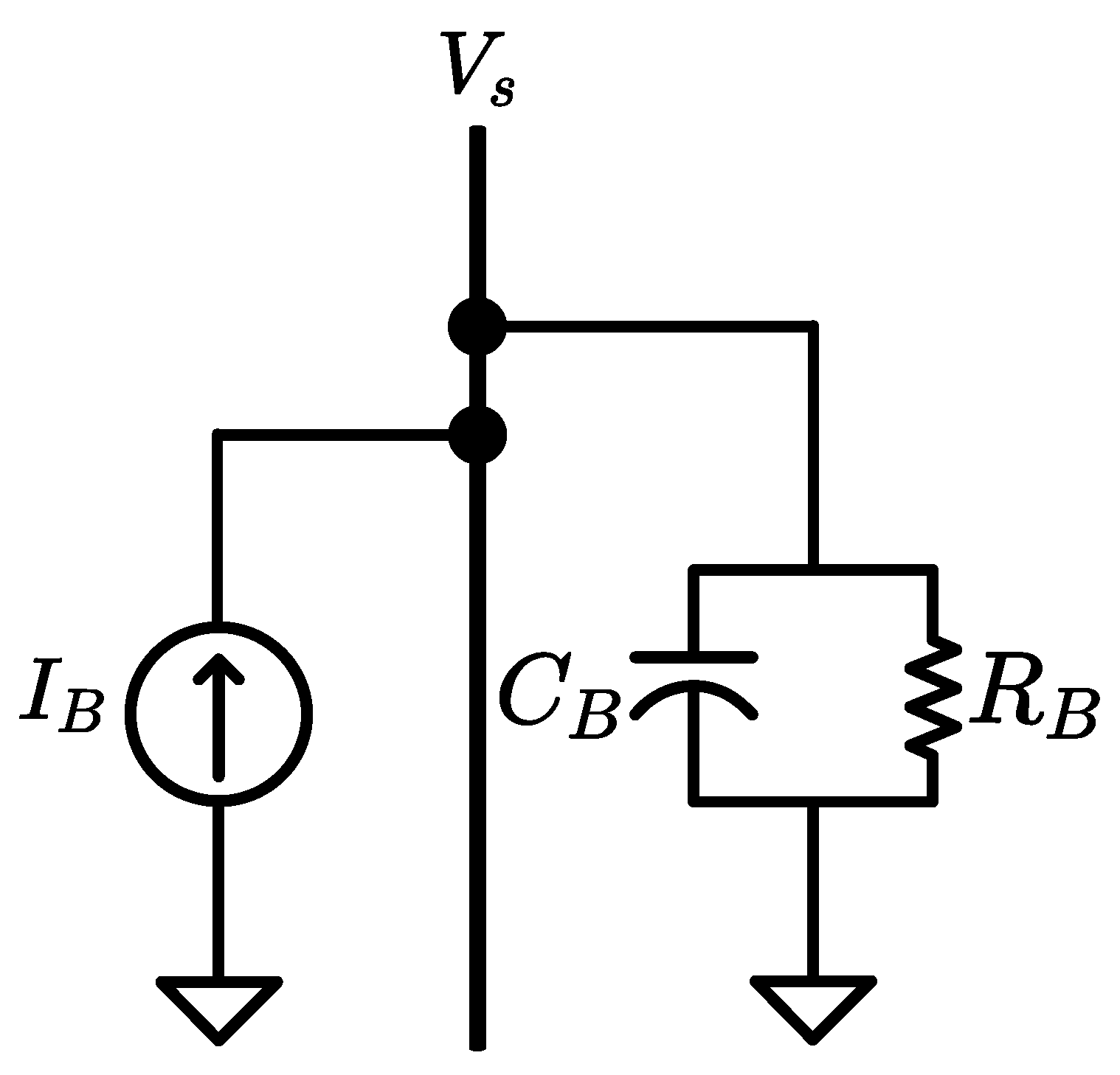
Figure 1 shows the considered system composed of a single DGU, modeled as a current source, serving a parallel resistor-capacitor load, both connected to a common bus.
2.1. DC Droop Control
For a DC system, the state equation for the bus voltage is
where
is the DC bus voltage and
is the DC load current.
According to Equation (
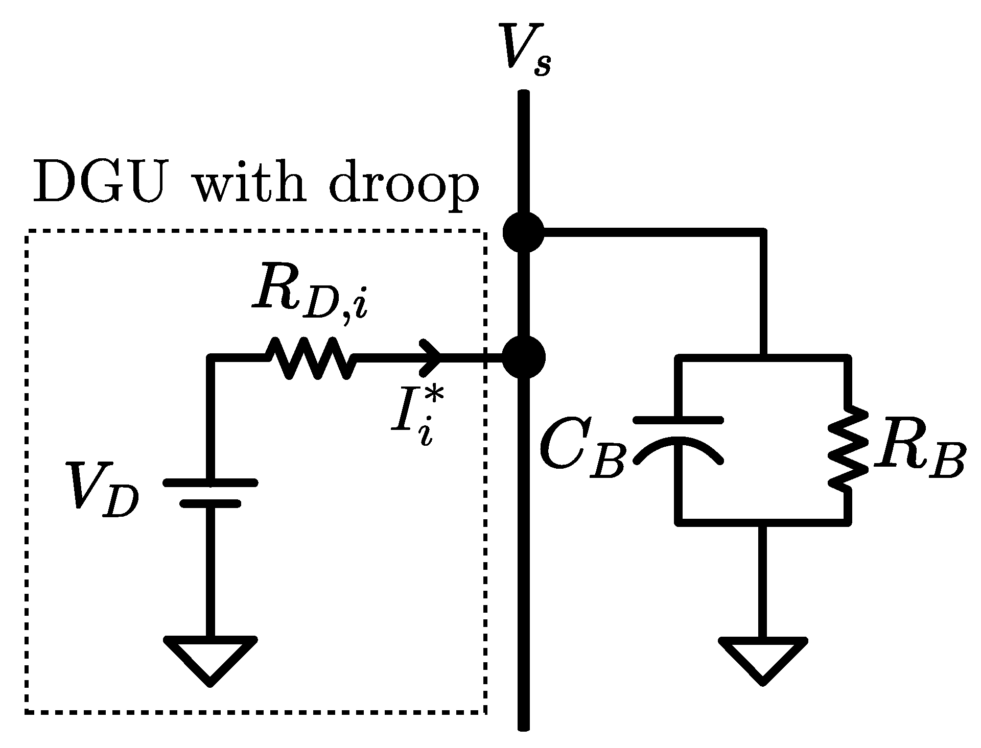
1), it is clear that the load current,
, depends on the bus voltage,
. Therefore, when multiple sources are feeding the load bus, the load current can be shared by implementing a virtual resistive impedance between the bus and each source [
8], as shown in
Figure 2. The reference for the current injected by the
ith source into the bus is given by
where
is the proportion of the load current from the
ith source, and
and
are the droop voltage setting and the droop virtual resistance, respectively.
2.2. DQ Droop Control
For an AC system, the state equations for the bus voltage in the abc-frame are
where
and
are vectors composed of the three-phase AC quantities. Under balanced conditions, the bus voltage is
and the load current is
with
,
,
, and
being the voltage amplitude, the current amplitude, the voltage phase angle, and the current phase angle, respectively.
After obtaining the state Equation (
3) for the time-varying AC system in the stationary abc-frame, a reference frame transformation is used to derive the state equations of the two equivalent DC systems in the rotating dq-frame.
The dq0 transformation, also known as the Park’s transformation, is a mathematical transformation that simplifies the three-phase AC quantities (abc-components) in the stationary abc-frame into three DC quantities (dq0-components) in the dq-frame rotating with the speed
. The equivalent dq0 vector is obtained by multiplying the three-phase vector by the dq0 power invariant transformation matrix
, defined by
with
is the angle between the rotating and fixed frame. For this scheme, the reference angle,
, can be chosen arbitrarily, as the rotating frame does not need to be synchronized with any reference signal. Therefore, the use of complicated PLLs is avoided. The rotating speed,
, of the dq0 frame is constant at the microgrid frequency.
By applying the dq0 transformation to (
3), the three state equations of bus voltages in the abc-frame are reduced to two equations in the dq-frame as
where
and
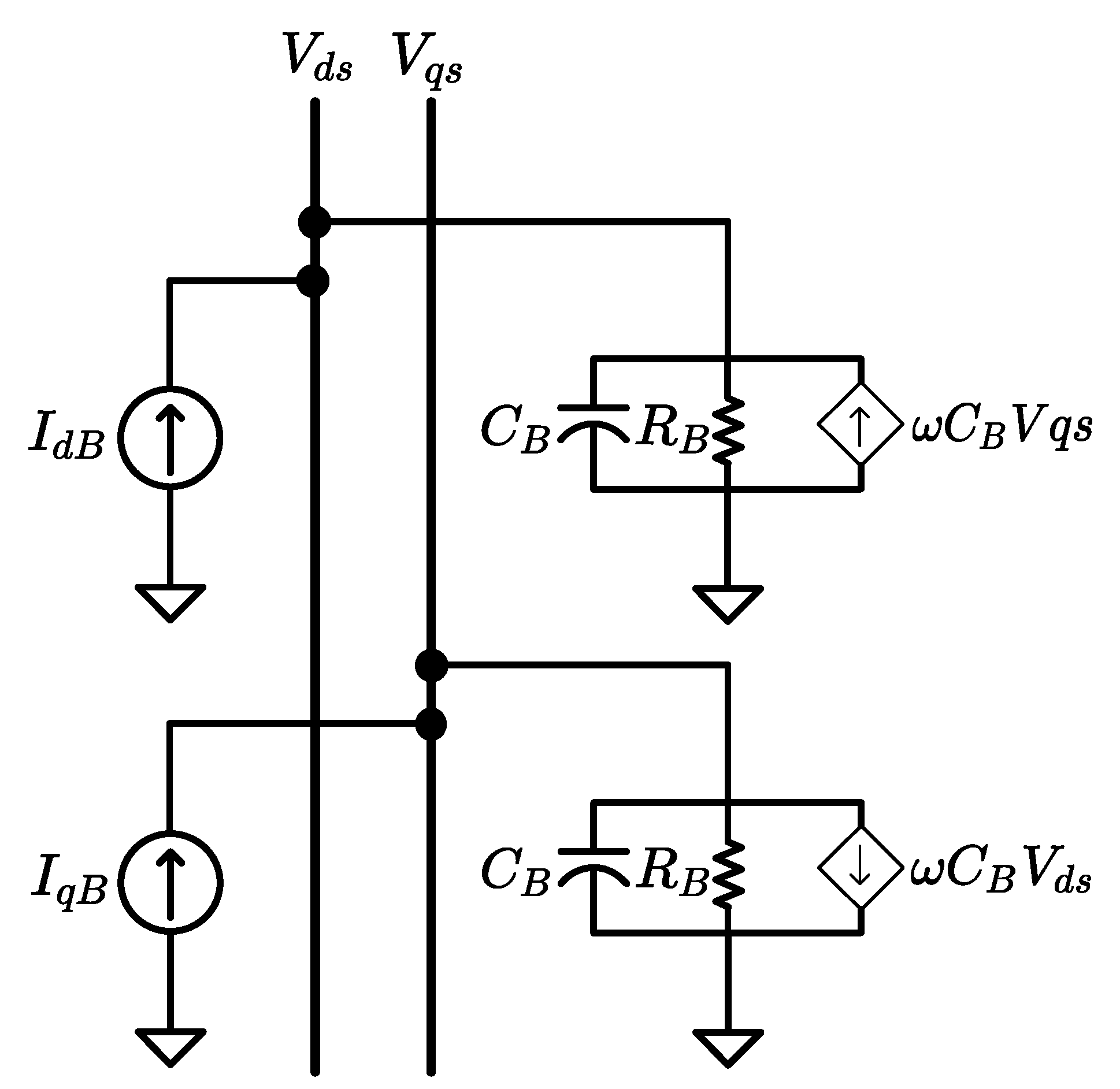
Note that for a balanced system, the zero component of the dq0 transformation is always equal to zero; therefore, it will be omitted for the rest of the discussion.
According to (7), the three-phase system of
Figure 1 can be seen as two equivalent DC systems, as shown in
Figure 3.
The two resulting DC systems are coupled to each other. However, the DC droop control presented in
Section 2.1 can be applied to independently share the d and q axis components of the load current by implementing a virtual resistance between the bus and the source on each of the d and q axis circuits, separately. The dq-components of setpoints for the current injected by the
ith source into the bus are given by
where
is the load current share of the
ith source,
and
are the droop voltage settings in dq coordinates, and
is the droop virtual resistance.
2.3. Droop Stability Analysis
A stability analysis is performed to demonstrate that the decoupled dq droop control loops can stabilize the system, even in the presence of coupling between the d and q axis circuits. It is assumed that the DGUs local controllers can maintain stability and track the current reference signals set by the droop controllers. Therefore, the injected bus currents of the DGUs are set equal to the desired setpoints. More details about the design of the decentralized local controllers and the microgrid stability analysis can be found in our previous works [
22,
23]. Then, the currents in Equation (7) can be replaced by the right-hand sides of Equation (10) to include the droop controller dynamics. The state equations of the closed-loop system are
Let
and
be the steady-state bus voltage in dq coordinates. The errors of the bus voltage are defined as
Then, the state space equation is given by
To perform the stability analysis, the Lyapunov second method is applied by choosing the Hamiltonian
of the system (
13) as a Lyapunov function candidate [
24]:
is a positive definite function that represents the energy stored by the system, and the power flow is the time derivative of the Hamiltonian
From Equation (15), it can be seen that the cross-coupling terms canceled each other out and that the time derivative of the Hamiltonian is negative definite. Therefore, the system under the proposed droop control is stable, and the coupling does not affect its stability and performance. Moreover, Equation (15) shows that the choice of the droop voltage settings and does not influence the stability of the system. However, they should be properly chosen to guarantee the nominal value of the bus voltage. The virtual resistance, , on the other hand, affects the steady-state error and the injected current transient, as small values of can cause significant current variation during the transient phase. This virtual resistance is responsible for setting the proportion of load sharing between the DGUs.
The main objective of droop control is to share the active and reactive power demand of the loads among the DGUs based on their rated power. By sharing the load current in the dq coordinates, the proposed droop control allows the sharing of active and reactive power between the DGUs. Indeed, the active power supplied by the
ith DGU is
where
is the total active power injected into the bus. Similarly, the reactive power supplied by the
ith DGU is
where
is the total reactive power injected into the bus.
2.4. Droop Settings
To share the load currents properly, the designer should set the load currents proportions between the DGUs. These shares can either be chosen proportional to the DGUs power rating, as for the conventional droop, or calculated using the decentralized power apportionment method from our previous work [
25]. The virtual resistances for the droop control are then chosen such that
Note that the sum of the load current proportions should be equal to one ().
In addition to setting the proportions for sharing the load between DGUs, the designer can choose the droop voltage settings,
and
, to maintain a desired bus voltage value under nominal conditions. Under nominal conditions, the dq-components of the nominal load current are
where
and
are the dq-components of the nominal bus voltage. Then, the following equality holds,
and the droop voltage reference settings are
More generally, for a load with the nominal active and reactive power
and
, the current setpoints
and
for the
ith DGU are
Thus, the reference voltage settings are
The proposed droop control is designed to share the active and reactive power demand, from the load side, between the DGUs in a decentralized manner using only local measurements without the need for communication among DGUs. The motivation for applying a DC-like droop control scheme to AC inverter-based microgrids is to exploit the inherent property of inverters to control their output waveform frequency accurately. For this purpose, an open-loop feedforward control scheme is used to regulate and synchronize the frequencies of the inverters.
The short-term loss of global synchronization of the Global Positioning System (GPS) and the long-term error accumulation of the crystal clocks are the main issues that hinder the use of these technologies for the synchronization of inverters [
2]. However, the GPS-disciplined oscillators that combine a crystal oscillator and a GPS receiver can overcome these issues. Indeed, the internal oscillator of each controller generates the signal frequency reference used by the pulse-width modulation (PWM) generator and the reference frame transformations, while the GPS receiver uses the GPS signal, if available, to correct the error of the oscillator keeping the frequencies of inverters synchronized [
26].
The droop controller of each DGU measures the voltage at the local bus, decomposes it into direct and quadrature components using the reference frame transformation presented in
Section 2.2, and calculates the d and q components of the reference current according to the droop characteristics expressed in (10). Error signals are then created from these references and fed to the dq-current control loops to produce the inverter output voltage setpoints used to generate the PWM signal for the hex bridge.
For simplification, the proposed droop control scheme is applied to an ideal current source feeding an RC load through a common bus, as shown in
Figure 1. However, this technique is designed for inverter-based islanded AC microgrids. Traditionally, inverters in islanded microgrids operate as controlled voltage sources; whereas, in grid-tied microgrids, they behave as controlled current sources. Nevertheless, current-controlled inverters have been proposed for islanded microgrids as well, as they have a fast and accurate response and a simpler structure [
27,
28,
29].
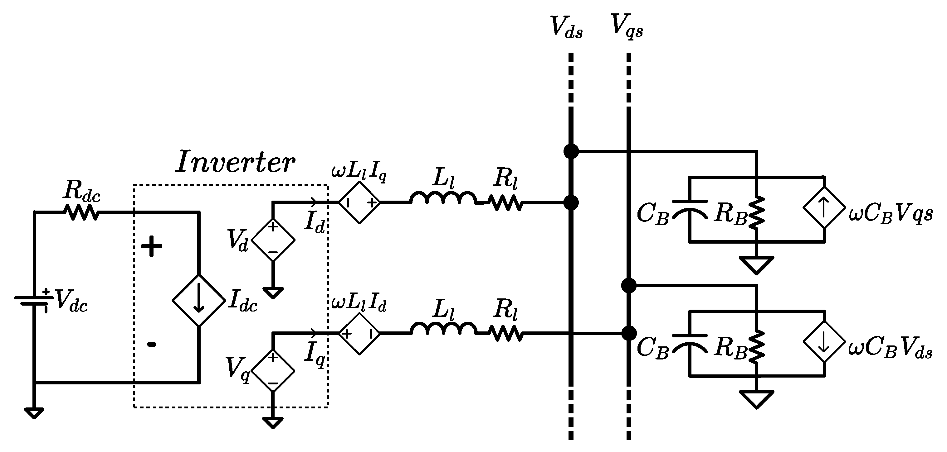
The microgrid model developed in [
30] will be used for the test and verification of the proposed droop control.
Figure 4 shows the RC load and the DGU composed of a DC voltage source and an inverter, connected to a common bus through a line/filter in dq coordinates.
3. Microgrid Model
The state equations for the inverter and the line/filter in the abc-frame are
where
,
, and
are vectors composed of the three-phase AC quantities of the line/filter current, the inverter output voltage, and the bus voltage, respectively.
Considering an average-mode model of the inverter, the 3-phase output voltages of the inverter are given by
where
represents the DC voltage source feeding the inverter. The duty cycles,
, fed to the inverter hex bridge are
where
is the depth of modulation also called the modulation index and
is the phase angle of the inverter output voltage.
By applying the dq0 transformation to (
24), the state equations of the inverter and the line/filter in the dq-frame are obtained:
where the output voltages of the inverter in dq-frame are
The state equations of an AC inverter-based microgrid with
N DGUs connected to a common bus are obtained by combining Equations (7) and (27) for
, such that
4. Simulation Results
The system of
Figure 4 was simulated using the SystemModeler software based on the state equations of the AC inverter-based microgrid with a single DGU in Equation (29) and the parameters given in
Table 2. Two droop methods were implemented and compared in this simulation: (1) the proposed droop control method using Equation (10) and (2) the conventional droop control method using the following equation [
13],
where
and
V are the references for the DGU frequency and voltage amplitude, respectively, and
and
have values at no load.
m and
n are the droop gains.
While the system is operating in a steady-state, the load resistance,
, was stepped up from
to
.
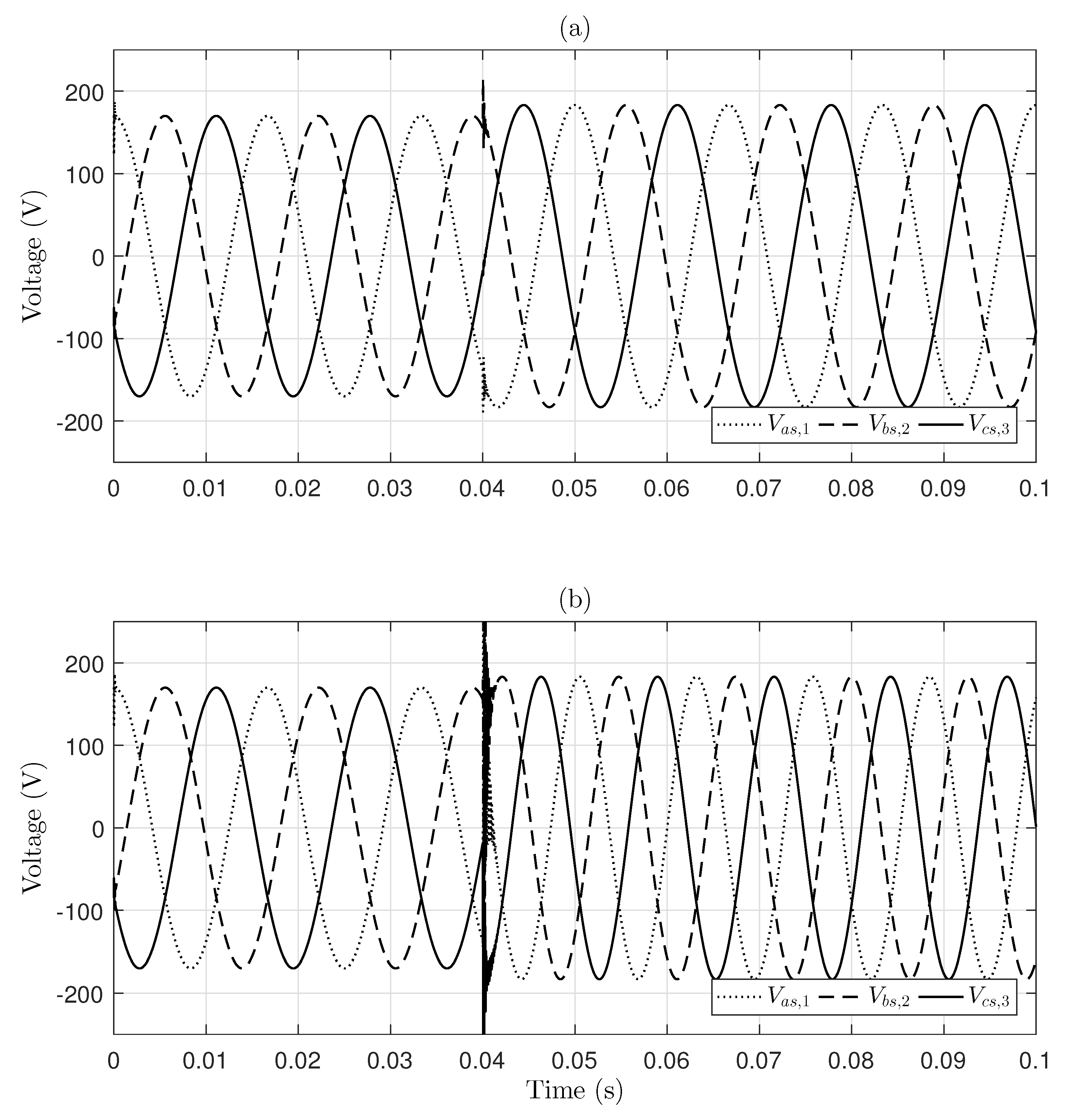
Figure 5 shows the three-phase bus voltage response with (a) the proposed droop control method and (b) the conventional droop control method. It can be seen that, under nominal conditions, the two droop control methods guarantee the 170 V nominal value of the bus voltage amplitude.
Figure 5 also shows that, after the load change transient, both methods maintain stable operation of the microgrid with a bus voltage amplitude of 183 V, instead of 170 V. This voltage deviation is common for droop control as it needs a secondary control loop to restore the voltage to its set value. However, the DGU with the proposed droop control operates at a fixed frequency of 60 Hz; whereas, in
Figure 5b, it can be clearly seen that the DGU with the conventional droop control changes the frequency when the load changes. Therefore, for the same voltage deviation, the proposed droop control method was able to maintain a fixed frequency contrary to the conventional droop method. Note that the frequency droop gain is usually very small; however, in this simulation, a large value was used for qualitative illustration rather than performance comparison.
5. Hardware-In-The-Loop Experimental Results
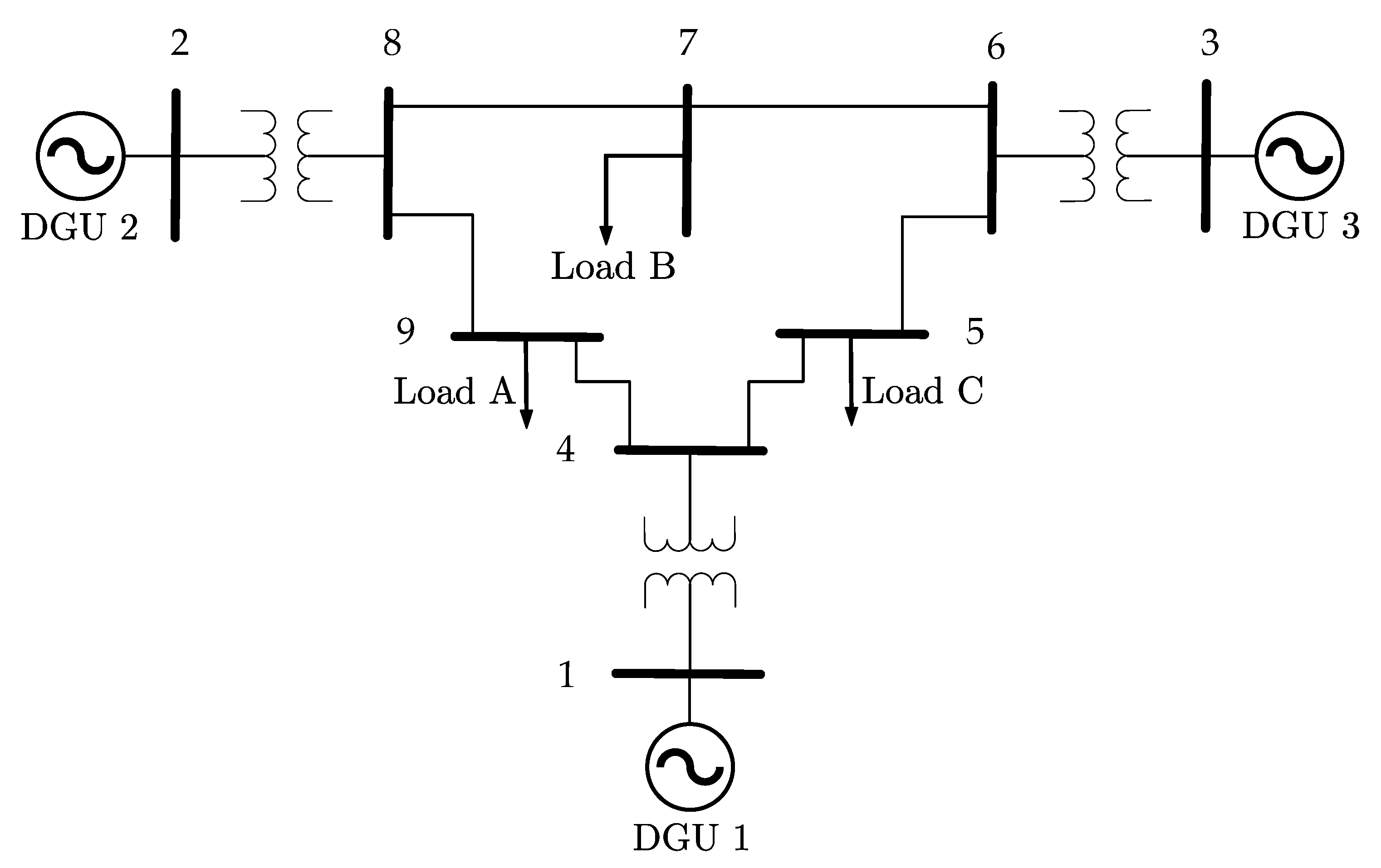
This section demonstrates the performance of the droop control proposed in this paper, in terms of sharing active and reactive power proportionally and maintaining the bus voltages in the allowed range. The proposed droop control is applied to the WSSC 9-bus test system that represents a simplified model, with three sources and nine buses, of the Western System Coordinating Council (WSCC) [
19]. The WSSC 9-bus test system of
Figure 6 is composed of nine buses with three DGUs, three transformers, and three RC Loads. The model of the DGUs and the RC loads used with this system are presented in
Section 4.
The proposed droop control was implemented in Simulink and integrated, via the Real-Time Interface, to the dSPACE DS1104 R&D Controller Board to control the WSSC 9-bus test system built in the Typhoon HIL600 emulator, using the parameters given in
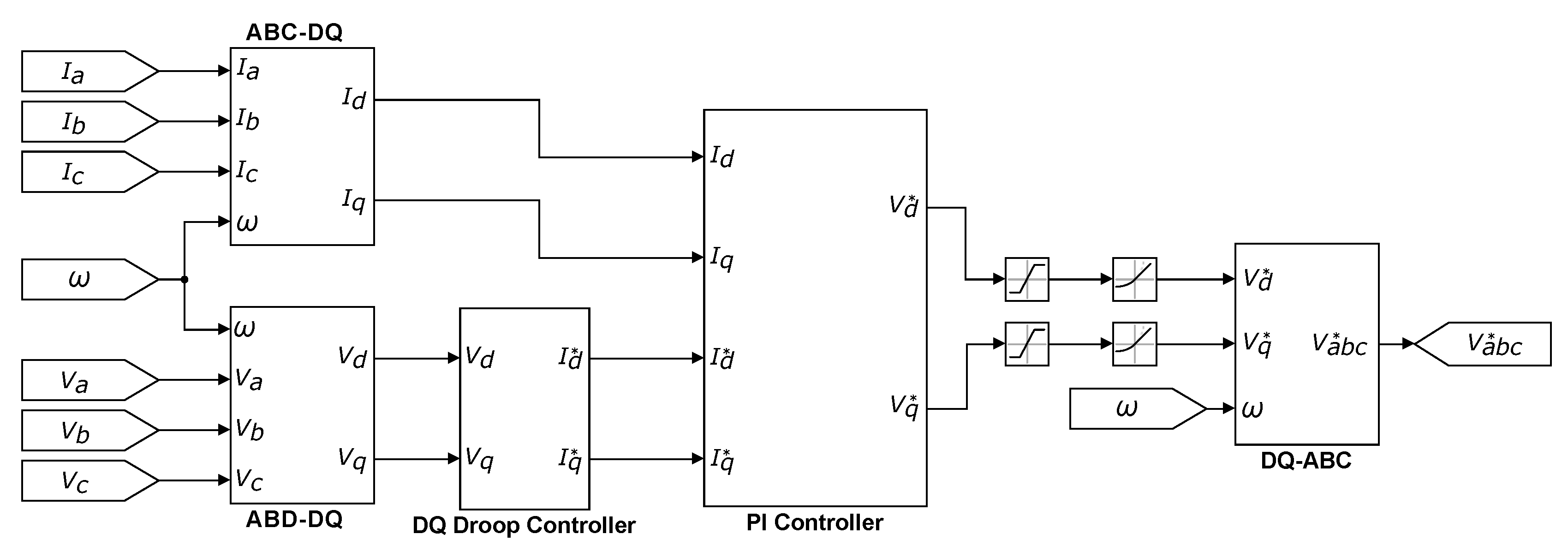
Table 3. An inner feedback control loop was designed to ensure the tracking of the DGUs current references set by the droop controller. This control loop was implemented as a proportional-integral (PI) controller designed based on the Hamiltonian Surface Shaping and Power Flow Control (HSSPFC) design technique [
22,
23,
31].
Figure 7 shows the schematic of the Simulink model of the droop controller and the PI control loop.
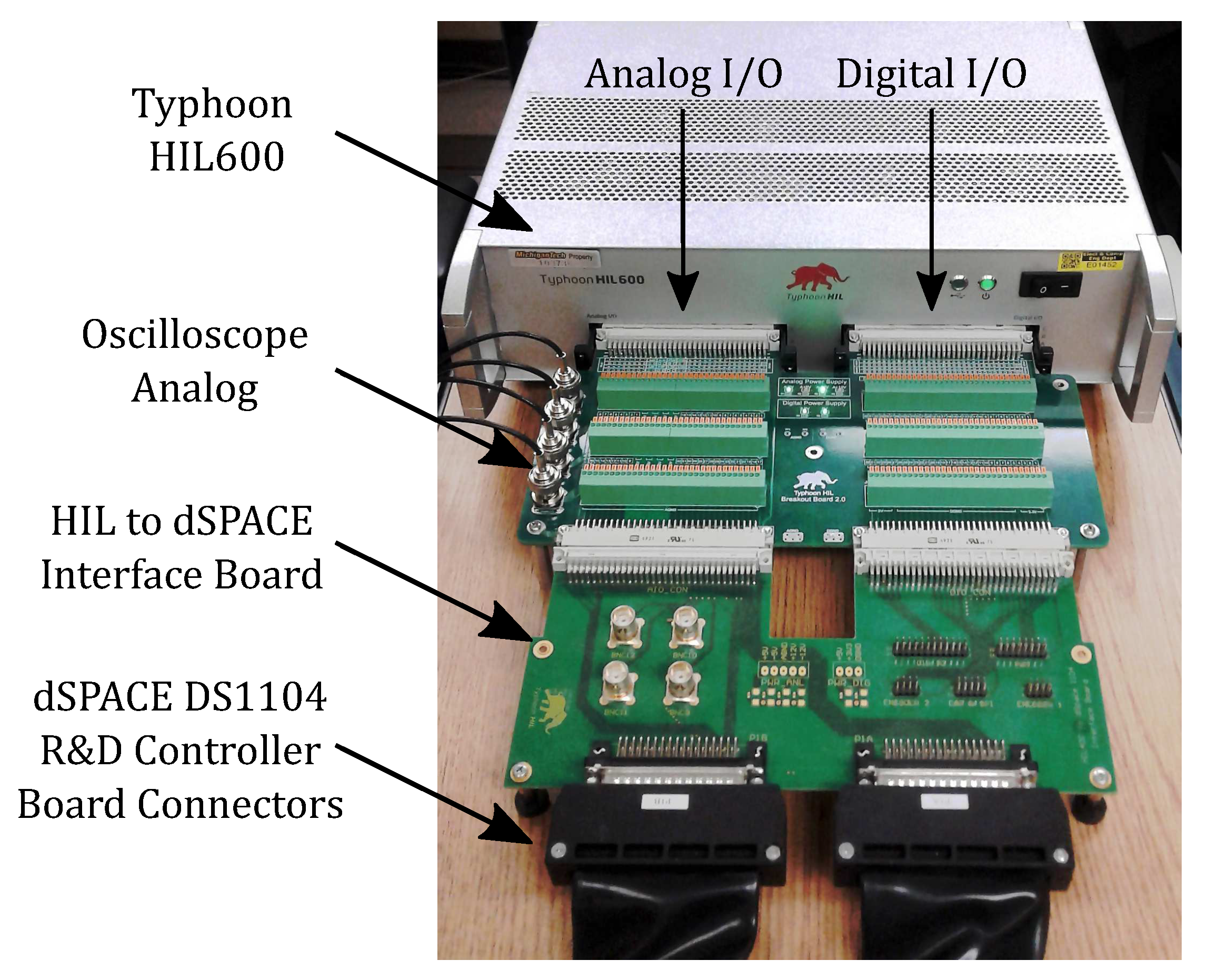
Figure 8 shows the Typhoon HIL600 with hardware-in-the-loop (HIL) to dSPACE interface board that connects it to the dSPACE DS1104 R&D Controller Board.
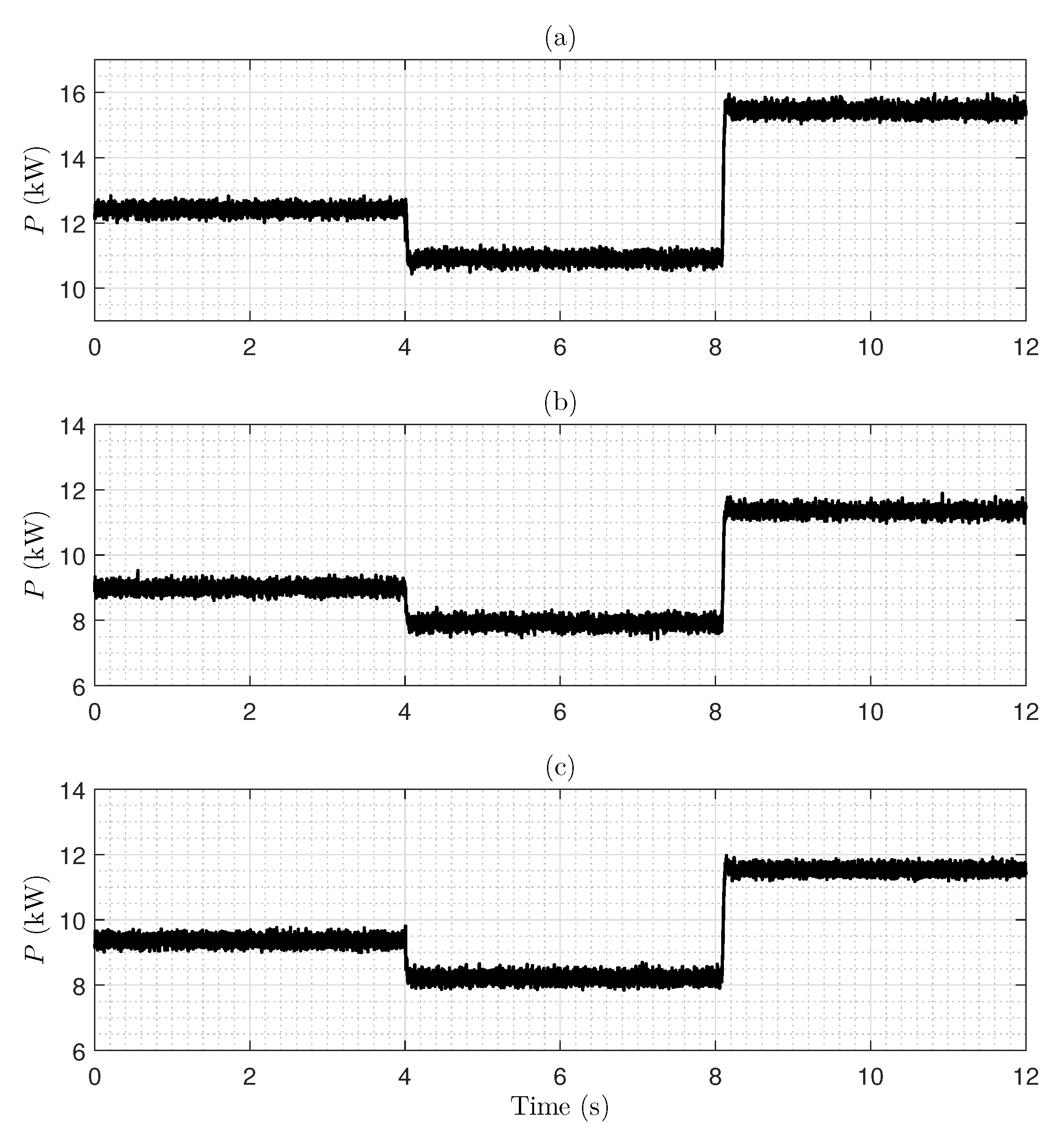
For this simulation, the inverters are operated at a 60 Hz fixed frequency. The shares of the DGUs are set such that and . At s, the resistance of Load A is stepped up to , then at s, the resistance of Load C is stepped down to .
Figure 9 shows the HIL simulation results for active power-sharing between the DGUs in the WSCC 9-bus test system. It reveals that the proposed droop control can accurately share active power between the three DGUs according to the predefined proportions. Indeed, the total active power absorbed by the three loads is
kW, and it can be seen that the active power supplied by DGU 1 is
, and the active powers supplied by DGU 2 and DGU 3 are
. Moreover, after each load step change, the active power supplied by the DGUs changes proportionally. This shows that, unlike conventional droop control, the proposed droop control can still guarantee proper power-sharing even after the load step changes without altering the microgrid frequency.
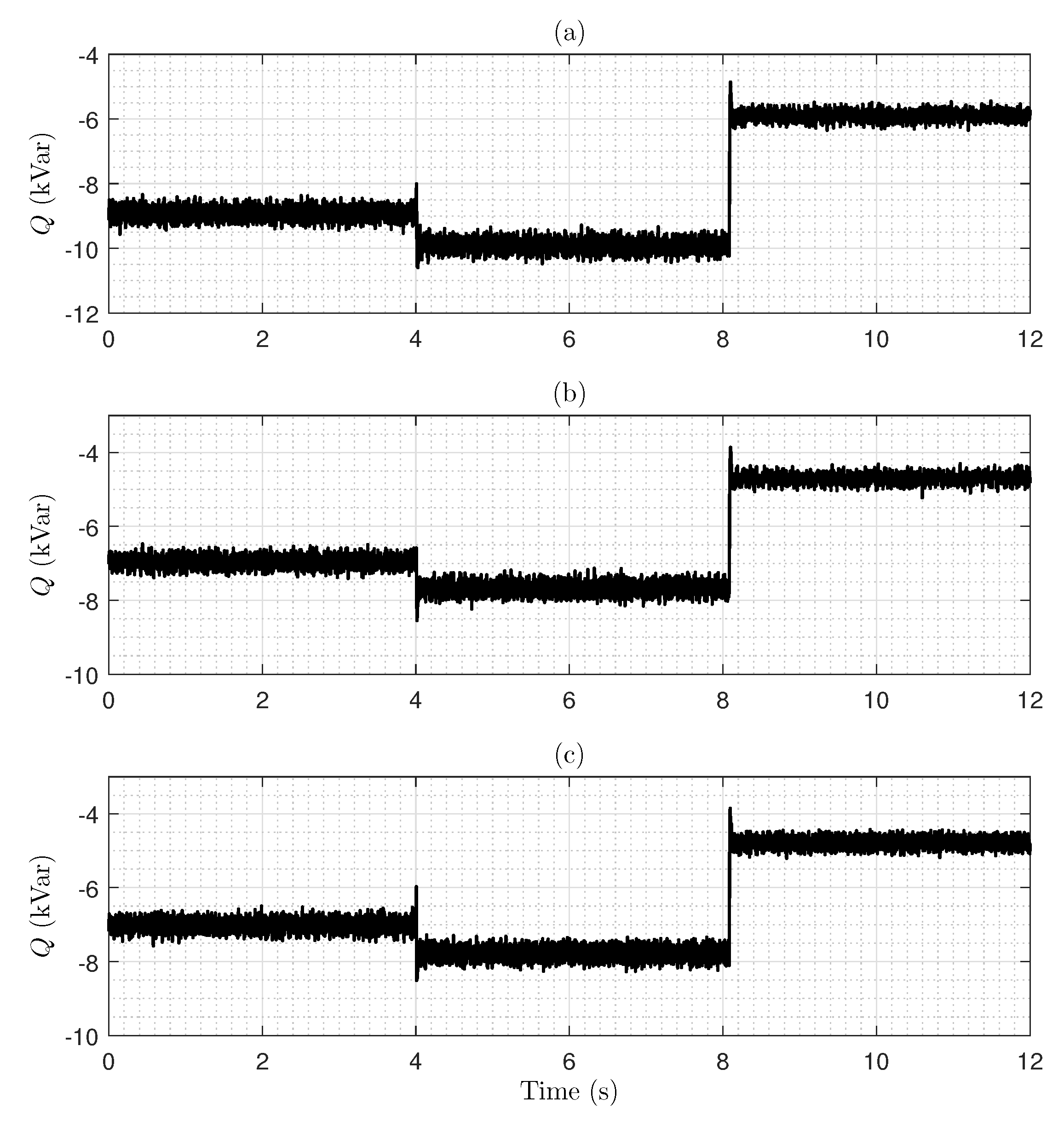
The HIL results in
Figure 10 show that the proposed droop control also shares the reactive power between the DGUs with respect to the proportions. The reactive power supplied by DGU 1 is
kVar, which represents
of the total reactive power absorbed by the loads (
kVar), while the reactive power supplied by DGU 2 (
kVar) guarantees
of
, same as DGU 3. Furthermore, the DGUs respond to the load step changes by changing the reactive power supplied according to the set proportions.The results of
Figure 9 and
Figure 10 show that, by simply sharing the direct and quadrature component of the load current, the proposed droop control was able to guarantee accurate sharing of both active and reactive power, separately.
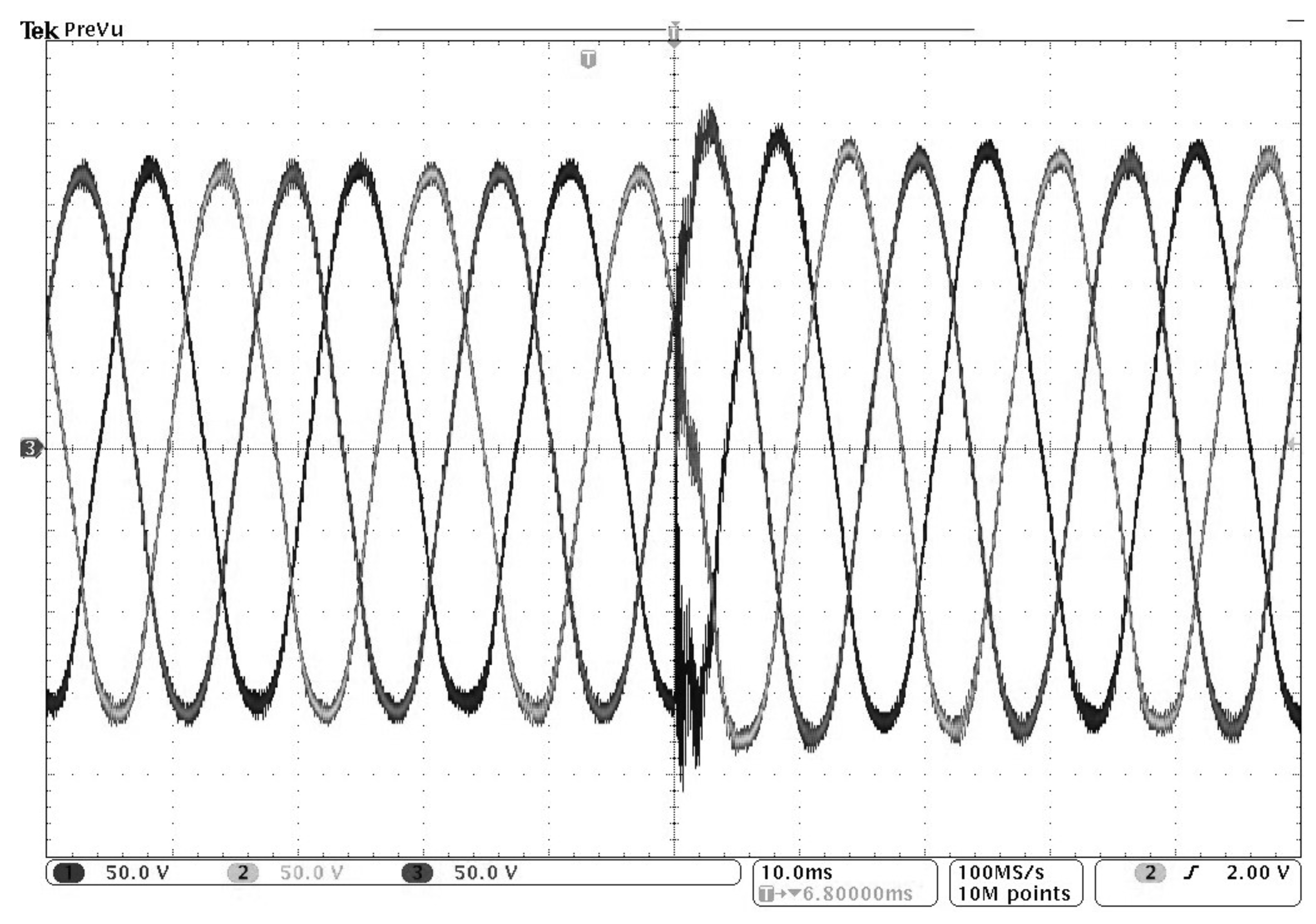
Figure 11 shows the HIL oscilloscope image of the three-phase voltage in Bus 5. The vertical scale of the oscilloscope is 50 V per division, whereas the horizontal scale is 10 ms per division. Under nominal conditions, the bus voltage amplitude is equal to the nominal value of 170 V. After the load step change, the system enters a transient state for half a cycle before the bus voltage stabilizes at 180 V. As expected, after the load change, the bus voltage maintained a 5.8% voltage deviation from its nominal value. This can be explained by the fact that, from a control point of view, the dq droop control is equivalent to a proportional controller that sets the current reference proportionally to the error between the bus voltage and the droop voltage setting. Thus, the intrinsic steady-state error of the proportional controller translates to a voltage deviation that makes the bus voltage magnitude load-dependent. Moreover, voltage harmonics can be noticed in
Figure 11, which is a common issue in islanded microgrids. Both steady-state deviation and voltage harmonics require an improved hierarchical control scheme, such as the one presented in references [
32,
33]; however, this is out of the scope of this paper since it only focuses on primary droop control. Note that the frequency measured by the oscilloscope remained constant after the load change.
The HIL simulation results demonstrate the ability of the proposed droop control to
guarantee nominal values of the load buses voltages and ensure proper sharing of the active and reactive power under nominal condition and
stabilize the microgrid and maintain the load buses voltages while accurately sharing the active and reactive power between DGUs after the load step change.

 ,
, 


