MEDUSA: A Low-Cost, 16-Channel Neuromodulation Platform with Arbitrary Waveform Generation


Department of Electrical and Computer Engineering, College of Engineering, Boise State University, 1910 W University Dr, Boise, ID 83706, USA
*
Author to whom correspondence should be addressed.
Electronics 2020, 9(5), 812; https://0-doi-org.brum.beds.ac.uk/10.3390/electronics9050812
Submission received: 17 March 2020
/
Revised: 29 April 2020
/
Accepted: 7 May 2020
/
Published: 15 May 2020
(This article belongs to the Special Issue Design and Application of Biomedical Circuits and Systems)
Abstract
:Neural stimulation systems are used to modulate electrically excitable tissue to interrogate neural circuit function or provide therapeutic benefit. Conventional stimulation systems are expensive and limited in functionality to standard stimulation waveforms, and they are bad for high frequency stimulation. We present MEDUSA, a system that enables new research applications that can leverage multi-channel, arbitrary stimulation waveforms. MEDUSA is low cost and uses commercially available components for widespread adoption. MEDUSA is comprised of a PC interface, an FPGA for precise timing control, and eight bipolar current sources that can each address up to 16 electrodes. The current sources have a resolution of 15.3 nA and can provide ±5 mA with ±5 V compliance. We demonstrate charge-balancing techniques in vitro using a custom microelectrode. An in vivo strength-duration curve for earthworm nerve activation is also constructed using MEDUSA. MEDUSA is a multi-functional neuroscience research tool for electroplating microelectrodes, performing electrical impedance spectroscopy, and examining novel neural stimulation protocols.
1. Introduction
Electrical stimulation is a broadly applied technique in neuroscience research and bioelectronic clinical therapies. Direct electrical stimulation of peripheral nerves has been shown to modulate physiological functions such as blood pressure [1] and rheumatoid arthritis [2]. In the central nervous system, electrical stimulation has been used to treat chronic pain via spinal cord stimulation [3] and alleviate the symptoms of Parkinson’s disease with deep-brain stimulation [4]. Most neuromodulation is performed with charge-balanced, rectangular biphasic pulses [5] or monophasic pulses with passive recharge in order to conserve energy in an implanted device [6]. However, conventional electrical stimulation through a microelectrode has the highest current density at the electrode-tissue interface, meaning neural activation is maximized at the interface. Therefore, recent work has focused on utilizing novel stimulation waveforms to focalize electrical stimulus deeper in tissue away from the electrode interface. One proposed method is to use temporally interfering sinusoids with a small frequency offset (e.g., 10 Hz) and relatively high carrier frequency (≥1 kHz) so as to not excite tissue near the electrode interface [7]. Prior work has shown cell firing entrained to the low offset frequency deep into tissue where the sinusoids interfere. Relatedly, another method is to use multiple intersectional short pulses from several electrode pairs to focus the stimulus [8]. This technique relies on the stimulus-duration relationship of excitable cells and many time-offset electrode pairs, where the targeted cell will integrate several subthreshold stimulation pulses. Novel stimulation paradigms also look to maximum stimulation efficiency to minimize energy dissipated by implantable devices. Overall, stimulation efficiency is the product of the efficiency of the electronics and how effective the stimulation waveform is at inducing the desired physiological response. For example, exponential waveforms are less energy efficient than rectangular waveforms in activating neurons and axons, but systems with exponential waveforms may be more efficient overall due to the way they can be generated with electronics [9].
While many ASIC implementations boast a powerful stimulation feature set [10,11,12,13], they are not widely available for low-cost neuroscience research. Since kilohertz stimulation frequencies have only recently garnered more interest, conventional neuromodulation equipment is not suitable for high frequency stimulation [14]. Furthermore, expensive benchtop equipment makes multi-channel or highly parallelized experiments impractical. As such, there is growing interest and research need in creating low-cost neuromodulation hardware [13,15]. In this work, we present MEDUSA, a low-cost platform capable of generating arbitrary, current-controlled stimulus waveforms. The platform can create high-resolution (<16 nA) currents of ±5 mA with ±5 V compliance. Additionally, the sinusoidal stimulus can be used for electrical impedance spectroscopy [16,17] or kilohertz frequency nerve block. This paper describes the architecture and characterization of the implemented system.
2. Materials and Methods
2.1. MEDUSA System Architecture
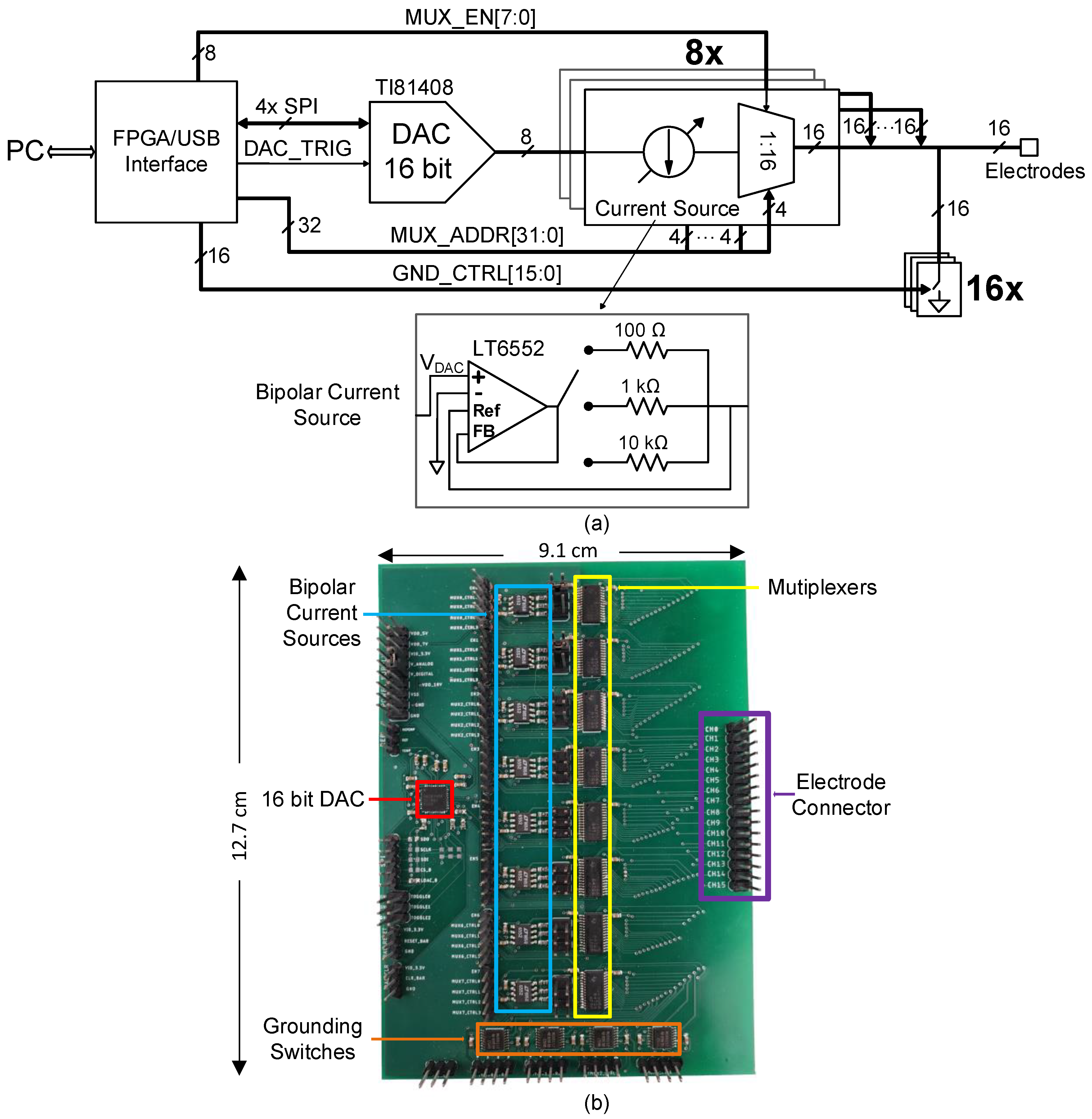
The implemented system architecture and system components are shown in Figure 1. MEDUSA was comprised of an FPGA/USB interface (XEM6010, Opal Kelly, Portland, OR, USA), an 8-channel, 16-bit DAC (DAC81408, Texas Instruments, Dallas, TX, USA), 8 voltage-controlled bipolar current sources that can address 16 channels through a 16:1 multiplexer, and a shorting switch for each channel. Users could configure stimulation waveform parameters through a Python interface on the PC. The settings were transferred via USB, and precise stimulation timing control was facilitated by the FPGA. The FPGA communicated with the DAC via SPI (serial peripheral interface) operating at 24 MHz and an asynchronous trigger signal (DAC_TRIG) that updated the DAC outputs. The grounding switches, controlled by the FPGA, could be used as a current return or used to clear residual charge from the electrode interface after stimulation. The multiplexers and grounding switches were selected for low leakage currents (<10 nA) and suitable low on-resistance (250–300 ).
2.2. Bipolar Current Source
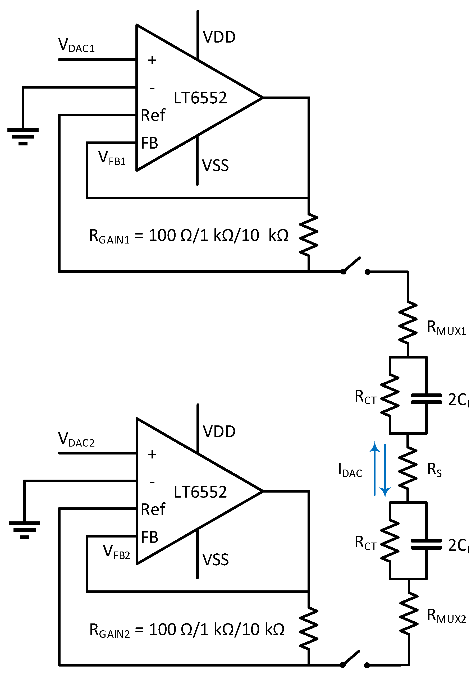
The voltage-controlled bipolar current sources in Figure 2 used an amplifier with auxiliary differential inputs (LT6552, Linear Technology, Milpitas, CA, USA), and either current source was able to sink or source current. The auxiliary input was used in a feedback loop to force the equivalent voltage of across the output resistor . Therefore, in order to balance the current sinking and sourcing, the input voltage and must be differential. The resulting output current for each channel is given as:
where was switchable for each current source to 100 , 1 k, or 10 k and was chosen on resolution and dynamic range requirements.
Since the amplifier output could swing rail-to-rail (±5 V) and source or sink 70 mA, the maximum current output was limited by the input common-mode of the auxiliary amplifier input (VSS to VDD − 1.4 V). The amplifier could use an asymmetric supply (VSS = −5 V, VDD = 7 V) to extend the voltage compliance range at the expense of current source linearity. The total voltage supply required for an anodic stimulation pulse could be calculated to be:
where is the spread resistance of the electrode, is the on-resistance of the multiplexer (≈100 ), is the stimulation pulse width, and is the interface capacitance of the electrode. The additional 1.4 V of headroom was required by the amplifier for anodic stimulation due to input common mode limitations. Note that this bipolar current source could also be used for unipolar current stimulation, since this system had active grounding switches, so the second electrode could be short to ground and made it unipolar.
2.3. Digital Timing Control
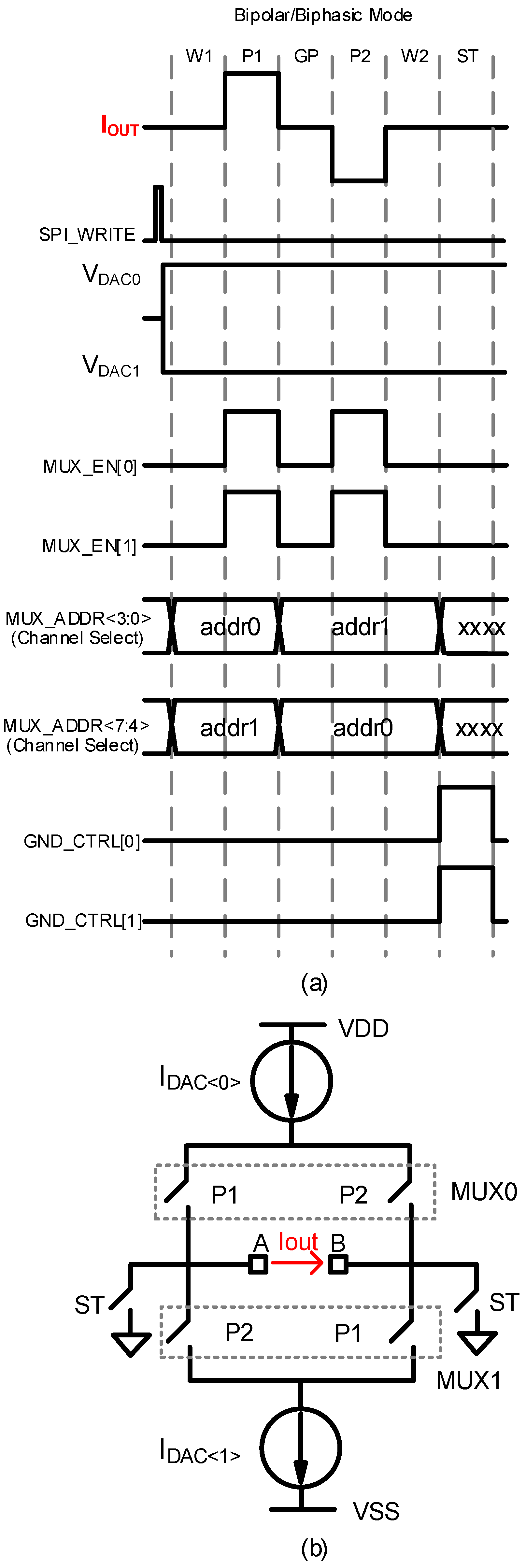
Digital timing for the pulse mode had 6 phases (W1, P1, GP, P2, W2, and ST) in one stimulation cycle (Figure 3a). Each phase had a resolution of 1 s with 16 bits of range (65,536 s max) and could be programmed independently. The stimulation frequency (cycle repetition rate) was independent to be set through the wait periods (W1 and W2). Stimulation frequencies lower than 15 Hz were implemented with software control using the Python interface. The DAC was configured using SPI to operate in differential mode prior to the start of digital stimulation cycle. During the first pulse (P1), both multiplexers were enabled to allow current to flow through the electrodes, while for the second pulse (P2), the multiplexer addresses were swapped so the polarity of current flowing was reversed. During the shorting time (ST), the grounding switches were enabled to short the electrodes to ground.
Arbitrary waveform mode used a lookup table to update the output current at pre-defined intervals. The lookup tables were written in the FPGA firmware to ensure high timing precision. Each point from the lookup table was written into DAC using SPI at a minimum delay of 2 s. Note that the multiplexer control and grounding signals could be controlled simultaneously with an arbitrary waveform. Key specifications for MEDUSA are shown in Table 1.
3. Results
3.1. System Transfer Function
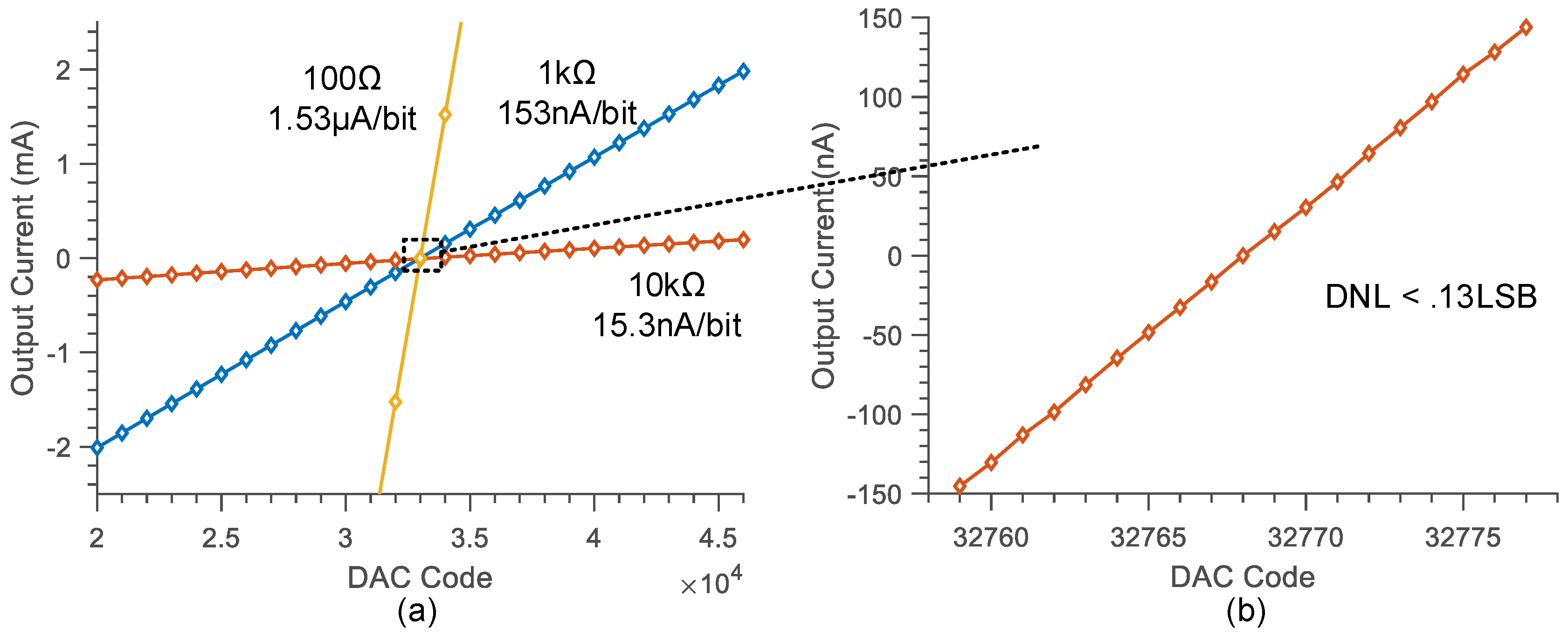
To validate the transfer function of MEDUSA, we measured the output current for all three gain modes (R = 100 , 1 k, and 10 k) for current ranges of ±5 mA, ±2 mA, and ±250 A. The output current was measured using a source meter at 0 V. The output current vs. digital DAC code is shown in Figure 4a, where the digital code was stepped into increments of 1000. To verify the linearity and resolution, we swept 20 codes around the zero-crossing and measured an LSB of 15.3 nA with a DNL of 0.13 LSB over that range (Figure 4b). Typically, such small currents are not biologically relevant for neuromodulation systems; however, microelectrode electroplating current levels can be on the order of 100 nA [18]. Note that the input bias current of the amplifier was roughly 10 A, but this offset was canceled through DAC calibration.
3.2. Compliance Voltage
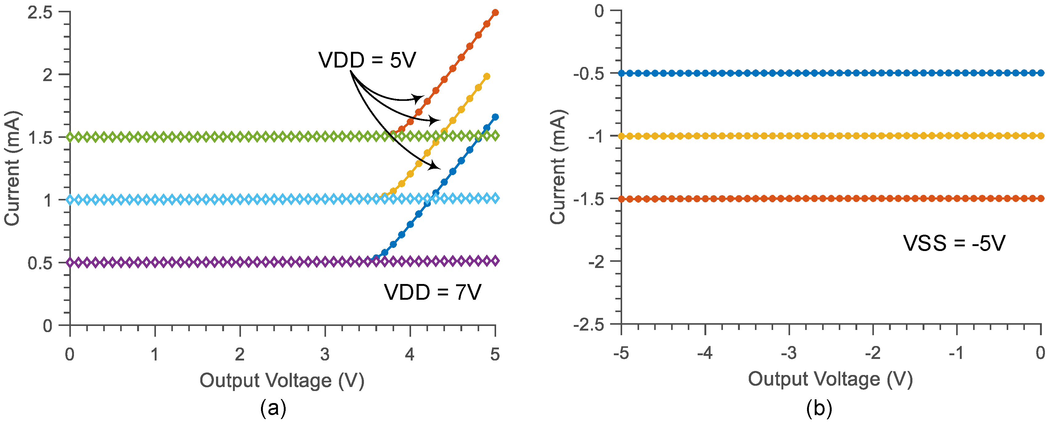
To verify the compliance voltage of the stimulator, we swept the load voltage on the source meter for programmed currents (Figure 5). For anodic stimulation, the current output deviated from its specification by 10% around 3.6 V (VDD − 1.4 V). To ensure 5 V compliance, a VDD of 7 V could be used. Cathodic stimulation, however, was compliant with VSS due to the input common-mode range of the current source amplifier.
3.3. Arbitrary Waveform Generation
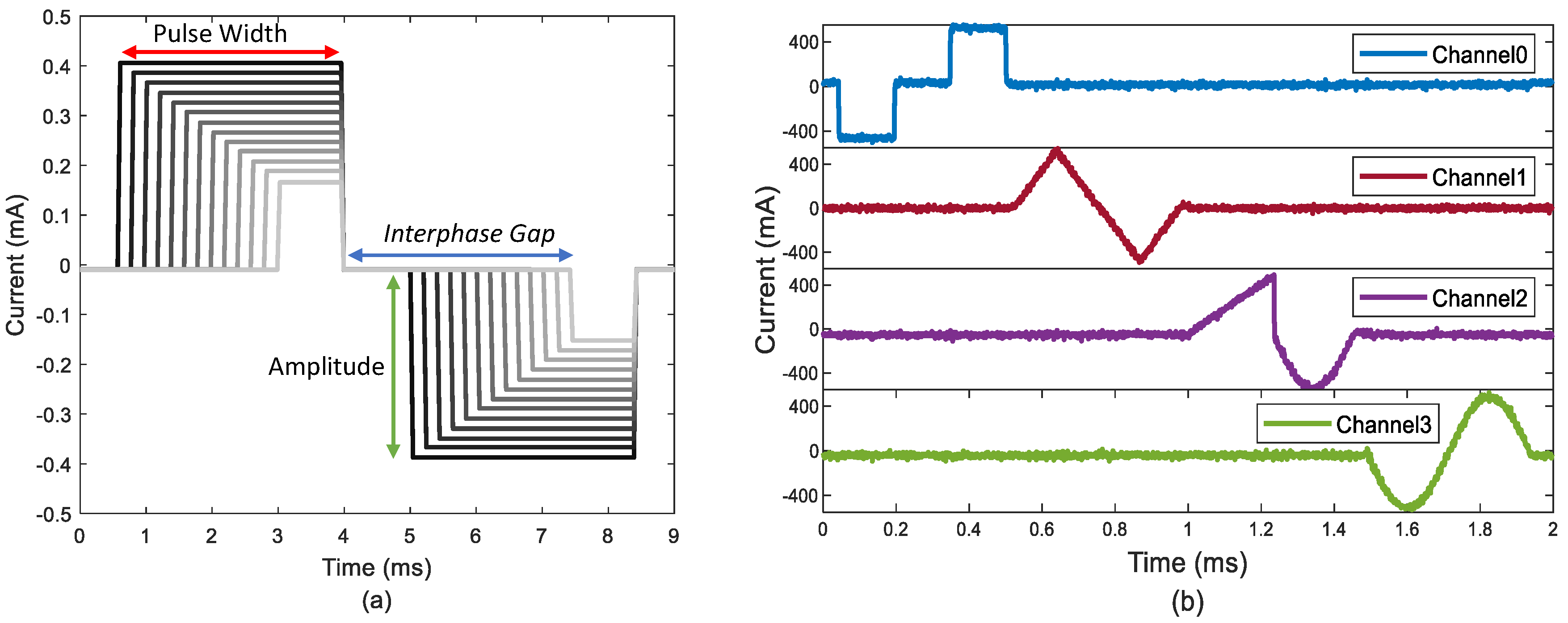
To demonstrate arbitrary waveform generation, we measured the voltage across a 1 k resistive load to ground during stimulation. Figure 6a shows a conventional biphasic waveform with rectangular pulses. All timing and amplitude parameters were configured by the user through the Python interface. The FPGA firmware implemented the timing diagram as shown in Figure 3a to generate the pulses, while the current amplitude for each phase was independently programmed via SPI. Each state of the waveform had a resolution of 1 s with 16 bits of programmability. The system could also generate arbitrary current stimulation (Figure 6b). In arbitrary waveform mode, the firmware used a lookup table that could be scaled dynamically through the Python interface. The temporal resolution in arbitrary waveform mode was 2 s, which was limited by the speed at which the DAC could update over SPI. In this mode of operation, the user could customize the scaling factor of the lookup table for both the period and amplitude of the arbitrary waveform.
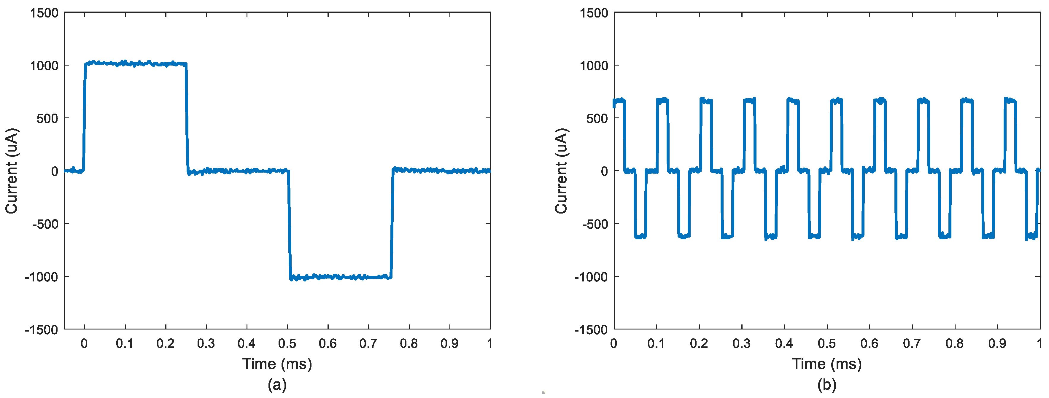
MEDUSA can easily achieve high-frequency stimulation (>1 kHz) without issue. The analog bandwidth was more than 2 MHz, so the stimulation frequency in arbitrary waveform mode was only limited by the DAC update speed. Figure 7a,b shows two biphasic stimulation waveforms at 1 kHz and 10 kHz using two types of stimulation methods discussed above. In Figure 7a, the 1 kHz biphasic stimulation was operating under arbitrary waveform mode using a lookup table update, while in Figure 7b, the 10 kHz stimulation used conventional MUX switch mode with DAC output preset at a certain voltage level.
3.4. Charge-Balancing In Vitro
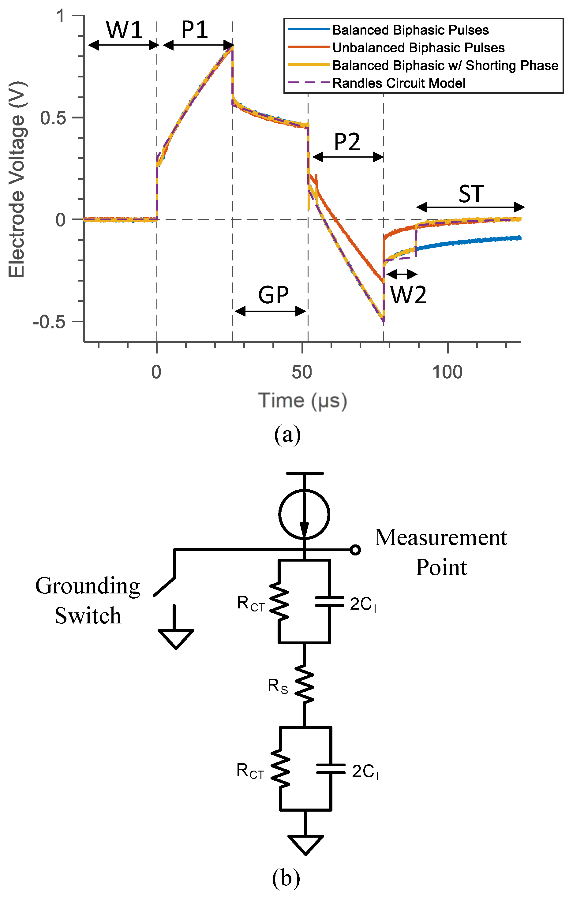
To demonstrate charge-balancing using MEDUSA in vitro, we immersed a custom microelectrode array in a saline bath and measured the voltage profile in response to biphasic stimulation. The electrode array was a rigid PCB with 0.5 mm diameter square immersion gold (ENIG) electrodes. A 3D-printed ring defined a well around the electrodes. While these electrodes had poor charge storage capacity relative to conventional stimulation electrodes, such as platinum-iridium, they were an apt test bench for charge-balance due to their nonlinearity during stimulation. As shown in Figure 8a, a balanced biphasic pulse (blue trace, A, s) generated a significant offset voltage mostly due to appreciable charge leakage during the interphase gap (s). Note that the offset voltage would eventually return to zero since one electrode was always at ground. To compensate for charge leakage during the interphase gap, less charge could be injected in the second phase by lowering its amplitude (red trace) or decreasing its duration. However, a practical implementation requires monitoring the offset after each stimulation sequence. For this reason, we implemented a grounding phase (ST) when electrodes could be shorted to ground, clearing any residual charge on the electrodes. To demonstrate the effect of the shorting switch, we added a 10 s wait time (W2) after the second pulse before enabling the shorting switch (yellow trace).
To confirm that leakage during the interphase gap was the source of the residual voltage offset, we created a Randles circuit model of the electrodes and simulated it with an ideal stimulator (purple trace, Figure 8a). Figure 8b is the Randles circuit model of the electrode-saline interface, and the biphasic current was injected from the top, illustrated by a current source . The values were determined empirically. During P1, positive current flowed through the electrode-saline interface, and the voltage jumped to ( is the spread resistance) and started to charge . During GP, the stimulation current was zero, and the electrode capacitor discharged. During P2, negative current (reverse polarity) flowed through network and discharged the electrode. If zero charge had been lost during GP, the electrode voltage would return to zero as the stimulation phases were perfectly matched. In this case, the lost charge during GP meant a negative offset voltage remained on the electrode. During ST, a shorting switch was enabled to eliminate the voltage offset.
3.5. Selective Stimulation Protocols
3.5.1. Temporal Interference
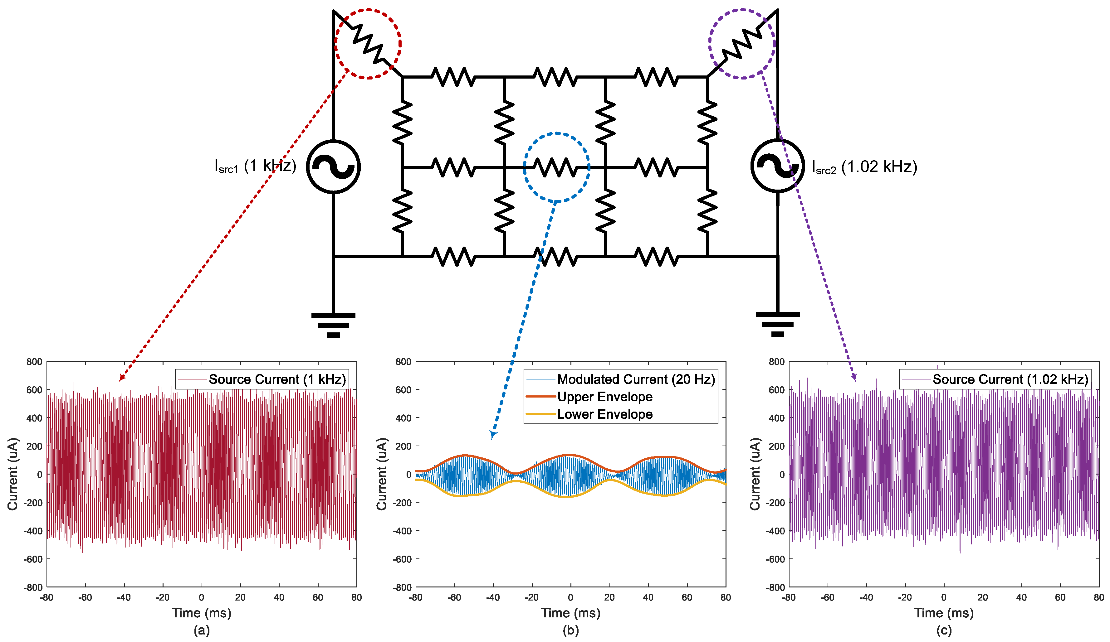
To demonstrate temporal interference [7], we injected two sine-wave currents (Figure 9a,c) at frequencies of 1 kHz and 1.02 kHz into a resistor mesh in Figure 9, which was used as a simplified electrical model for tissue. The sine-wave current was realized by updating DAC alternately with data from two different lookup tables and then sending currents to two channels simultaneously. This 2% difference of the number of points in these two lookup tables was able to create a 20 Hz frequency offset when one of the fast (100-point) sine-waves was operating at 1 kHz. Furthermore, the frequency and amplitude of sine-wave current could be independently configured to meet certain conditions. The current measured in the center resistor was modulated with an envelope frequency of around 20 Hz (Figure 9b), equal to the offset frequency of source currents.
3.5.2. Intersectional Short Pulse
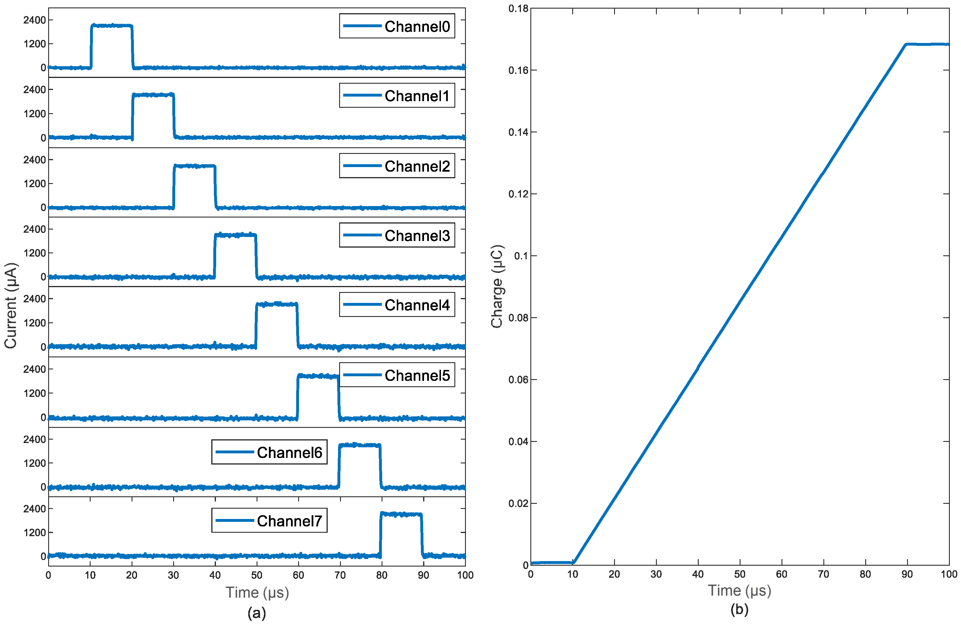
To demonstrate an intersectional short pulse (ISP) [8] stimulation protocol, we measured the voltages across eight resistive loads with 1 k resistance, and they were connected to the corresponding output channels of the stimulation system. The pulse current amplitude was set to be 1 mA and the pulse width to be 10 s in Figure 10a. The overall charge accumulated at the theoretical focal point showed a linear increase over time (Figure 10b). The ISP function was implemented by updating the DAC via a single lookup table and switching the MUX address incrementally from Address 0 to 7, so the stimulation current pulses were directed to preassigned output channels.
3.6. Comparison with State-of-the-Art
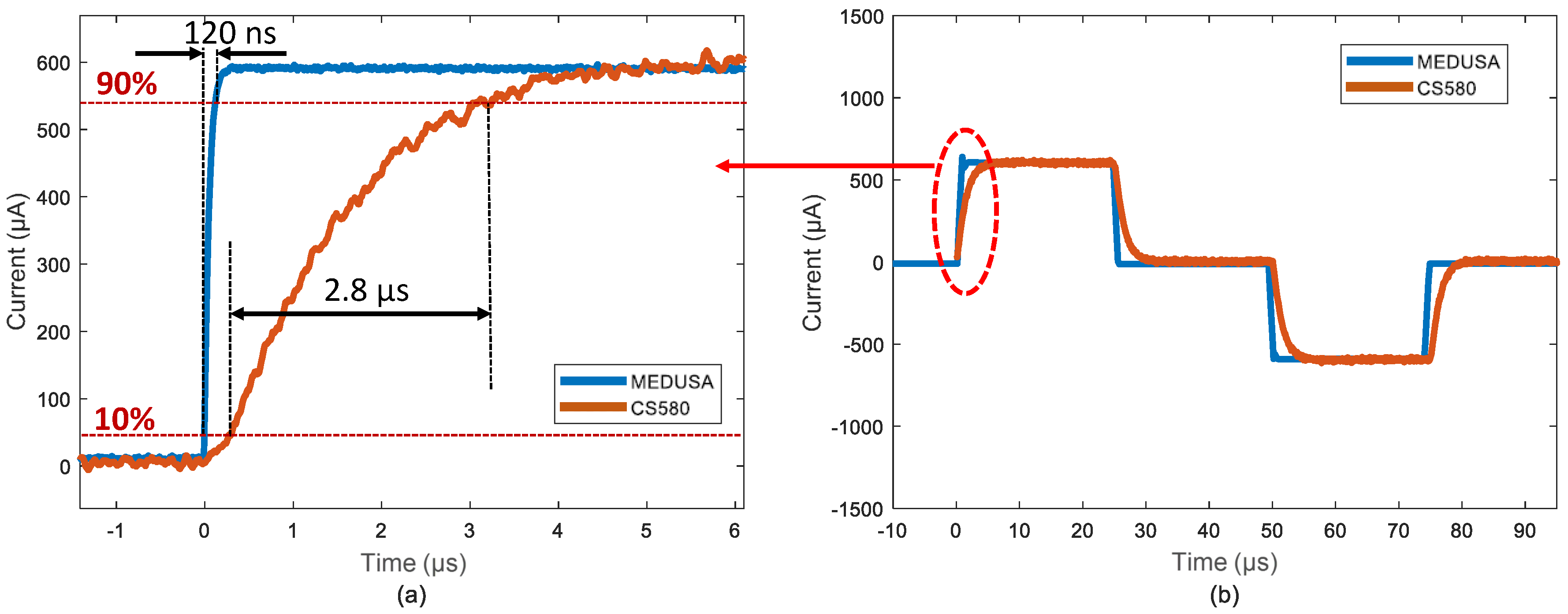
To demonstrate MEDUSA’s capability for high-frequency neuromodulation, we compared its rise time with a high-end commercial voltage-controlled precision current source (Stanford Research System CS580). For a conventional pulse stimulation, the 10–90% rise times 120 ns and 2.8 s, respectively, were measured across a 1 k resistive load with a 600 A current amplitude as shown in Figure 11a. This corresponded to analog bandwidths of 2.9 MHz and 125 kHz. MEDUSA achieved a rapid rise time by switching the multiplexer, allowing for the DAC and current source to settle during the first wait period (W1).
Table 2 shows a comparison of MEDUSA and other commercial or open source neuromodulators. MEDUSA had several key advantages: higher channel count, higher analog bandwidth, and seamless integration with an FPGA for complex waveform generation. Many other current sources required a function generator and a means to input an arbitrary waveform into the function generator, which made scaling to multiple stimulation channels impractical. MEDUSA also had the ability to short the electrodes to ground on command for charge balance to prototype novel in vivo stimulation protocols.
3.7. In Vivo Results
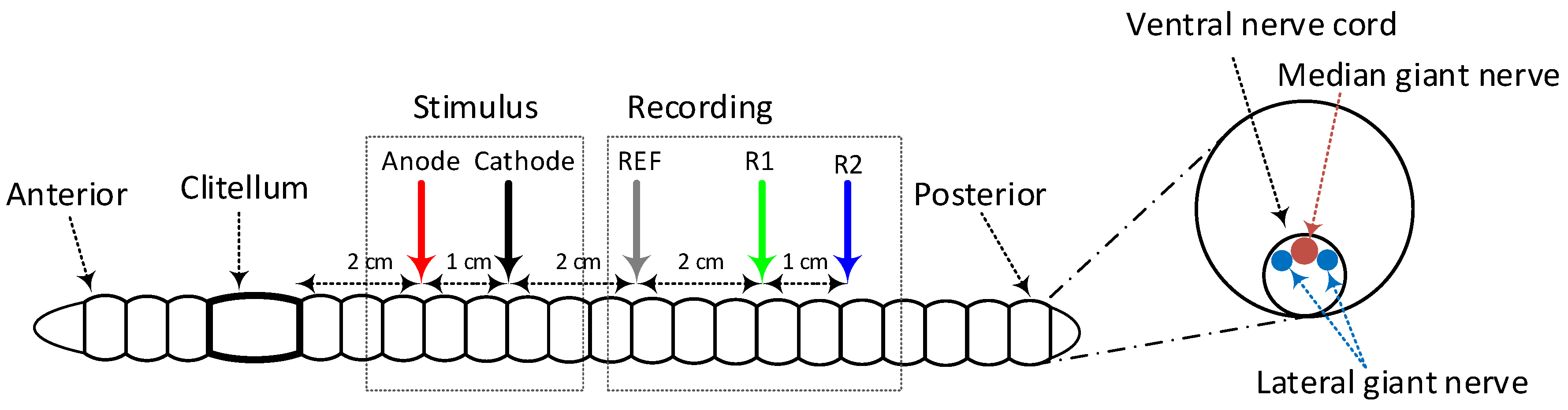
To demonstrate MEDUSA as a research platform, we performed a series of in vivo experiments using a common earthworm (Lumbricus terrestris). While no IACUC protocols were required, we ensured humane treatment by anesthetizing the earthworm using a 10% ethanol solution. An overview of the experimental setup is shown in Figure 12. The earthworm was placed dorsal side up, and electrode pins were inserted through the worm, fixing it in place. The stimulation anode was placed 2 cm caudally of clitellum and separated from the cathode by 1 cm. Recording channel R1 was placed 4 cm below the stimulation cathode. The recording reference (REF) was placed in the center between the stimulus cathode and R1 [19,20].
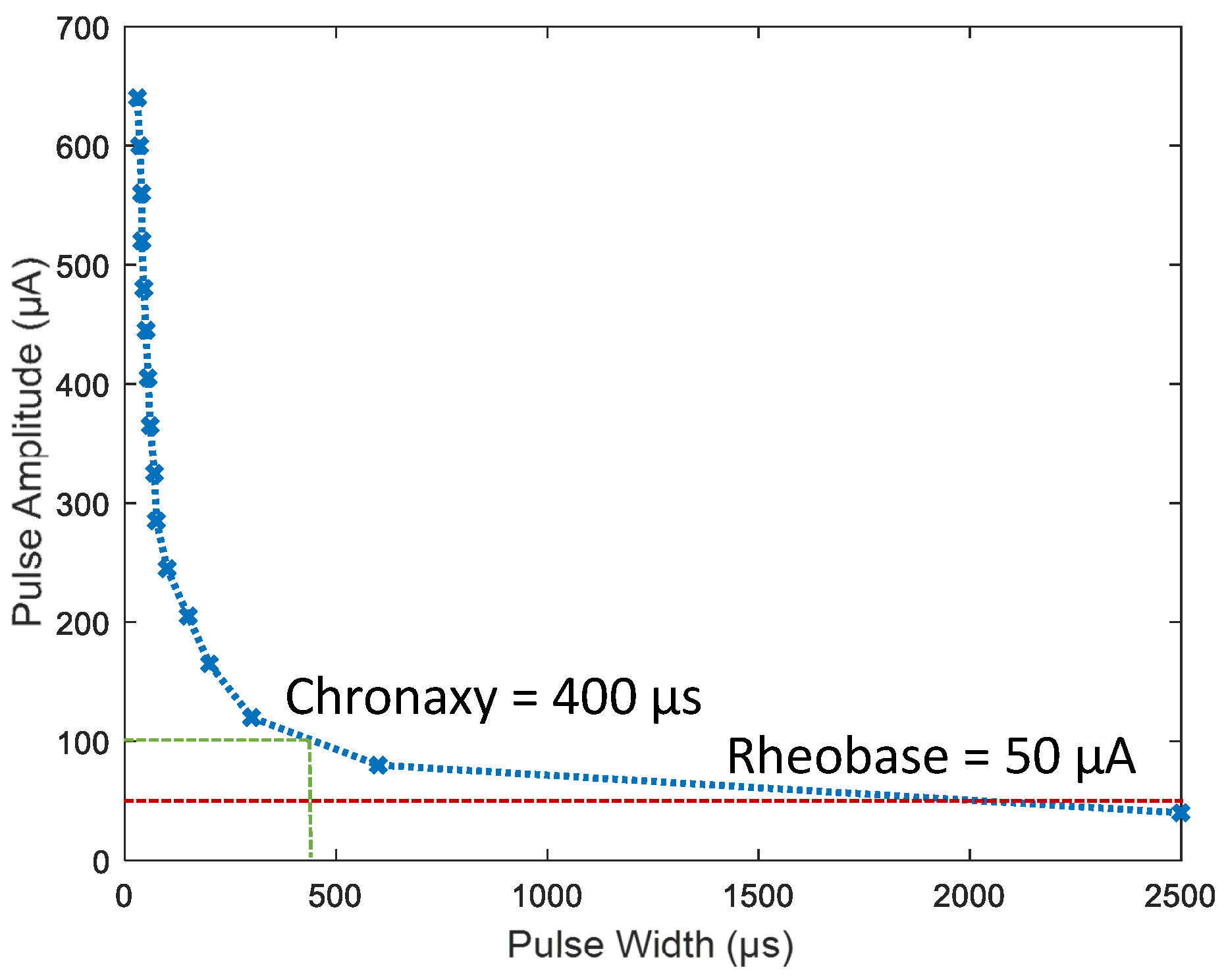
To build a strength-duration curve (Figure 13), we used monophasic current stimulation and swept pulse width and amplitude to determine the action potential threshold for the median giant nerve (MGN). Stimulation frequency was below 0.5 Hz to ensure that the nerve was not fatigued. The MGN showed a rheobase current of 50 A and a chronaxy of about 400 s [21].
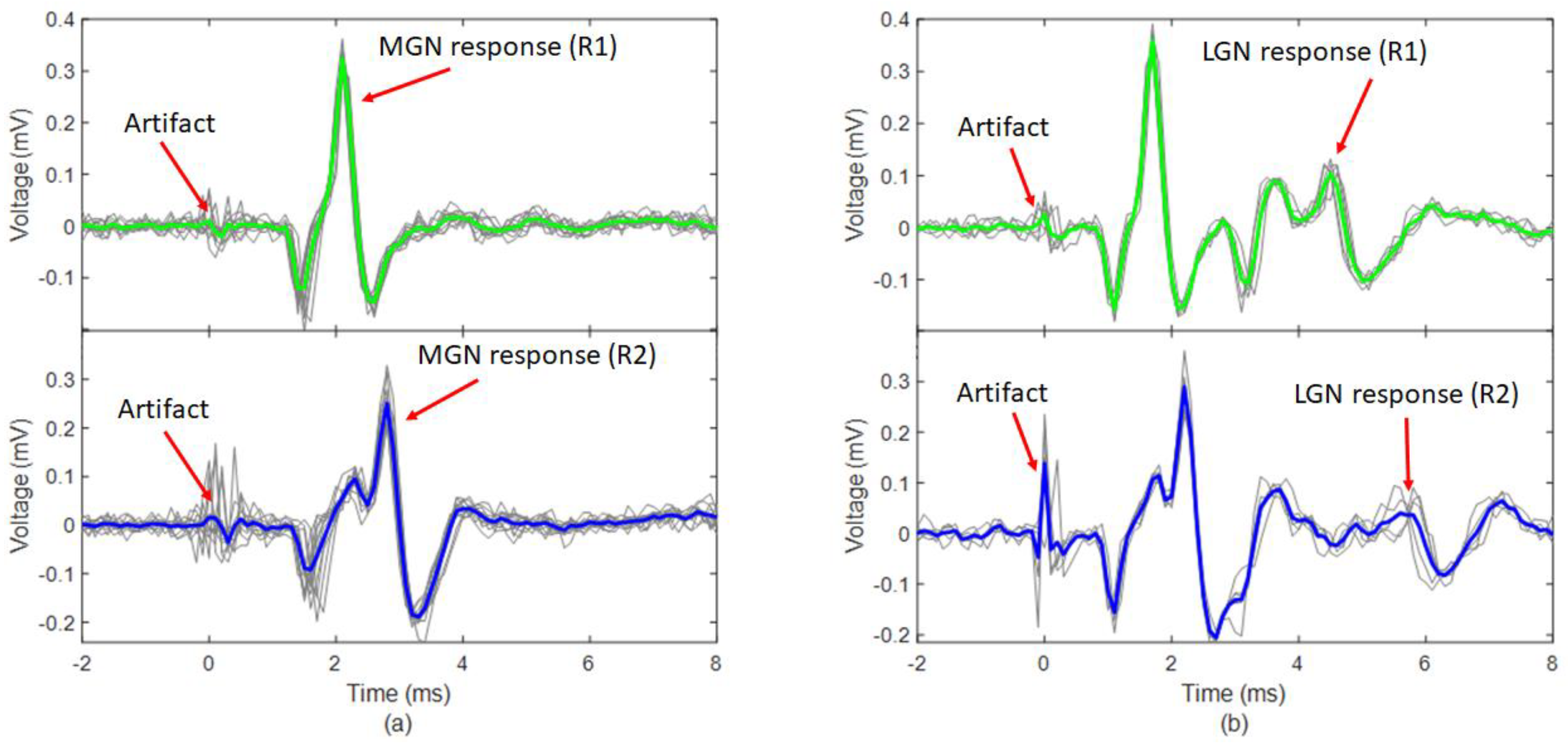
To verify a response from the lateral giant nerve (LGN), we used a fixed 100 s monophasic current pulse and increased amplitude starting at 200 A. Due to its smaller diameter, the LGN had a higher threshold and slower conduction velocity relative to the MGN. Figure 14a shows stimulus amplitudes below the LGN’s response threshold, while Figure 14b shows the response for stimulus amplitudes above the threshold. By comparing the delay between recording channels (R1 to R2), we estimated the conduction velocity of the MGN and LGN to be 20.0 m/s and 7.7 m/s, respectively.
4. Conclusions
We presented MEDUSA, a low-cost and high-performance 16-channel neural stimulation system built from off-the-shelf components. MEDUSA was intended to be a general purpose neuroscience research tool to explore novel, high-frequency, multi-channel stimulation paradigms. Our future work will migrate MEDUSA’s core functionality to a wireless system. However, wireless systems are far more constrained in terms of area and power and require more application-specific design implementations compared to general purpose platforms [12,22,23,24,25,26].
MEDUSA achieved a high dynamic range by combing a 16-bit voltage DAC and three orders of magnitude of gain selection in the current source. The system was capable of delivering monophasic and biphasic stimulation pulses with 1 s temporal resolution, DC currents, and arbitrary waveforms with a temporal resolution of 2 s. MEDUSA provides researchers with a low-cost, multi-functional neuroscience research tool for electroplating microelectrodes, performing electrical impedance spectroscopy, and examining novel neural stimulation protocols.
Author Contributions
Conceptualization, B.C.J.; circuit board design and assembly, F.T.; python software and FPGA firmware, F.T.; manuscript preparation, B.C.J. and F.T. All authors have read and agreed to the published version of the manuscript.
Funding
This work was made possible by an Institutional Development Award (IDeA) from the National Institute of General Medical Sciences of the National Institutes of Health under Grant #P20GM103408.
Conflicts of Interest
The authors declare no conflicts of interest.
References
- Plachta, D.T.T.T.; Gierthmuehlen, M.; Cota, O.; Espinosa, N.; Boeser, F.; Herrera, T.C.; Stieglitz, T.; Zentner, J. Blood pressure control with selective vagal nerve stimulation and minimal side effects. J. Neural Eng. 2014, 11. [Google Scholar] [CrossRef] [PubMed]
- Koopman, F.A.; Chavan, S.S.; Miljko, S.; Grazio, S.; Sokolovic, S.; Schuurman, P.R.; Mehta, A.D.; Levine, Y.A.; Faltys, M.; Zitnik, R.; et al. Vagus nerve stimulation inhibits cytokine production and attenuates disease severity in rheumatoid arthritis. Proc. Natl. Acad. Sci. USA 2016, 113, 8284–8289. [Google Scholar] [CrossRef] [PubMed] [Green Version]
- Chakravarthy, K.; Nava, A.; Christo, P.J.; Williams, K. Review of Recent Advances in Peripheral Nerve Stimulation (PNS). Curr. Pain Headache Rep. 2016, 20, 60. [Google Scholar] [CrossRef] [PubMed]
- Benabid, A.L.; Pollak, P.; Hoffmann, D.; Gervason, C.; Hommel, M.; Perret, J.E.; de Rougemont, J.; Gao, D.M. Long-term suppression of tremor by chronic stimulation of the ventral intermediate thalamic nucleus. Lancet 1991, 337, 403–406. [Google Scholar] [CrossRef]
- Merrill, D.R.; Bikson, M.; Jefferys, J.G.R. Electrical stimulation of excitable tissue: Design of efficacious and safe protocols. J. Neurosci. Methods 2005, 141, 171–198. [Google Scholar] [CrossRef]
- Stanslaski, S.; Afshar, P.; Cong, P.; Giftakis, J.; Stypulkowski, P.; Carlson, D.; Linde, D.; Ullestad, D.; Avestruz, A.T.; Denison, T. Design and validation of a fully implantable, chronic, closed-loop neuromodulation device with concurrent sensing and stimulation. IEEE Trans. Neural Syst. Rehabil. Eng. 2012, 20, 410–421. [Google Scholar] [CrossRef]
- Grossman, N.; Bono, D.; Dedic, N.; Kodandaramaiah, S.B.; Rudenko, A.; Suk, H.J.; Cassara, A.M.; Neufeld, E.; Kuster, N.; Tsai, L.H.; et al. Noninvasive Deep Brain Stimulation via Temporally Interfering Electric Fields. Cell 2017, 169, 1029–1041. [Google Scholar] [CrossRef] [Green Version]
- Vöröslakos, M.; Takeuchi, Y.; Brinyiczki, K.; Zombori, T.; Oliva, A.; Fernández-Ruiz, A.; Kozák, G.; Kincses, Z.T.; Iványi, B.; Buzsáki, G.; et al. Direct effects of transcranial electric stimulation on brain circuits in rats and humans. Nature. Commun. 2018, 9, 1–17. [Google Scholar] [CrossRef] [Green Version]
- Lee, H.M.; Howell, B.; Grill, W.M.; Ghovanloo, M. Stimulation Efficiency with Decaying Exponential Waveforms in a Wirelessly Powered Switched-Capacitor Discharge Stimulation System. IEEE Trans. Biomed. Eng. 2018. [Google Scholar] [CrossRef]
- Johnson, B.C.; Gambini, S.; Izyumin, I.; Moin, A.; Zhou, A.; Alexandrov, G.; Santacruz, S.R.; Rabaey, J.M.; Carmena, J.M.; Muller, R. An implantable 700 μW 64-channel neuromodulation IC for simultaneous recording and stimulation with rapid artifact recovery. In Proceedings of the 2017 IEEE Symposium on VLSI Circuits, Kyoto, Japan, 5–8 June 2017; pp. C48–C49. [Google Scholar] [CrossRef] [Green Version]
- Taschwer, A.; Butz, N.; Kohler, M.; Rossbach, D.; Manoli, Y. A Charge Balanced Neural Stimulator with 3.3 v to 49 v Supply Compliance and Arbitrary Programmable Current Pulse Shapes. In Proceedings of the 2018 IEEE Biomedical Circuits and Systems Conference, BioCAS, Cleveland, OH, USA, 17–19 October 2018; pp. 1–3. [Google Scholar] [CrossRef]
- Zhou, A.; Santacruz, S.R.; Johnson, B.C.; Alexandrov, G.; Moin, A.; Burghardt, F.L.; Rabaey, J.M.; Carmena, J.M.; Muller, R. A wireless and artefact-free 128-channel neuromodulation device for closed-loop stimulation and recording in non-human primates. Nat. Biomed. Eng. 2018, 3, 15–26. [Google Scholar] [CrossRef]
- Xu, J.; Guo, H.; Nguyen, A.T.; Lim, H.; Yang, Z. A bidirectional neuromodulation technology for nerve recording and stimulation. Micromachines 2018, 9, 538. [Google Scholar] [CrossRef] [PubMed] [Green Version]
- FallahRad, M.; Zannou, A.L.; Khadka, N.; Prescott, S.A.; Ratté, S.; Zhang, T.; Esteller, R.; Hershey, B.; Bikson, M. Electrophysiology equipment for reliable study of kHz electrical stimulation. J. Physiol. 2019, 597, 2131–2137. [Google Scholar] [CrossRef] [PubMed]
- Cermak, N.; Wilson, M.A.; Schiller, J.; Newman, J.P. Stimjim: Open source hardware for precise electrical stimulation. bioRxiv 2019, 757716. [Google Scholar] [CrossRef]
- Ibba, P.; Falco, A.; Rivadeneyra, A.; Lugli, P. Low-Cost Bio-Impedance Analysis System for the Evaluation of Fruit Ripeness. In Proceedings of the IEEE Sensors, New Delhi, India, 28–31 October 2018; pp. 1–4. [Google Scholar] [CrossRef]
- Avery, J.; Dowrick, T.; Faulkner, M.; Goren, N.; Holder, D. A versatile and reproducible multi-frequency electrical impedance tomography system. Sensors 2017, 17, 280. [Google Scholar] [CrossRef] [PubMed]
- Nick, C.; Thielemann, C.; Schlaak, H.F. PEDOT:PSS coated gold nanopillar microelectrodes for neural interfaces. In Proceedings of the 2014 International Conference on Manipulation, Manufacturing and Measurement on the Nanoscale, 3M-NANO, Taipei, Taiwan, 27–31 October 2014. [Google Scholar] [CrossRef]
- Shannon, K.M.; Gage, G.J.; Jankovic, A.; Wilson, W.J.; Marzullo, T.C. Portable conduction velocity experiments using earthworms for the college and high school neuroscience teaching laboratory. Am. J. Physiol. Adv. Physiol. Educ. 2014, 38, 62–70. [Google Scholar] [CrossRef] [Green Version]
- Follmann, R.; Rosa, E.; Stein, W. Dynamics of signal propagation and collision in axons. Phys. Rev. E Stat. Nonlinear Soft Matter Phys. 2015, 92, 032707. [Google Scholar] [CrossRef] [PubMed] [Green Version]
- Kladt, N.; Hanslik, U.; Heinzel, H.G. Teaching basic neurophysiology using intact earthworms. J. Undergrad. Neurosci. Educ. 2010, 9, 20. [Google Scholar]
- Yun, S.; Koh, C.S.; Jeong, J.; Seo, J.; Ahn, S.H.; Choi, G.J.; Shim, S.; Shin, J.; Jung, H.H.; Chang, J.W.; et al. Remote-controlled fully implantable neural stimulator for freely moving small animal. Electronics 2019, 8, 706. [Google Scholar] [CrossRef] [Green Version]
- Johnson, B.C.; Shen, K.; Piech, D.; Ghanbari, M.M.; Li, K.Y.; Neely, R.; Carmena, J.M.; Maharbiz, M.M.; Muller, R. StimDust: A 6.5mm3, wireless ultrasonic peripheral nerve stimulator with 82% peak chip efficiency. In Proceedings of the 2018 IEEE Custom Integrated Circuits Conference, CICC 2018, San Diego, CA, USA, 8–11 April 2018; pp. 1–4. [Google Scholar] [CrossRef] [Green Version]
- Lee, B.; Koripalli, M.K.; Jia, Y.; Acosta, J.; Sendi, M.S.E.; Choi, Y.; Ghovanloo, M. An Implantable Peripheral Nerve Recording and Stimulation System for Experiments on Freely Moving Animal Subjects. Sci. Rep. 2018, 8, 1–12. [Google Scholar] [CrossRef]
- Piech, D.K.; Johnson, B.C.; Shen, K.; Ghanbari, M.M.; Li, K.Y.; Neely, R.M.; Kay, J.E.; Carmena, J.M.; Maharbiz, M.M. A wireless millimetre-scale implantable neural stimulator with ultrasonically powered bidirectional communication. Nat. Biomed. Eng. 2020, 4, 207–222. [Google Scholar] [CrossRef]
- Freeman, D.K.; O’Brien, J.M.; Kumar, P.; Daniels, B.; Irion, R.A.; Shraytah, L.; Ingersoll, B.K.; Magyar, A.P.; Czarnecki, A.; Wheeler, J.; et al. A sub-millimeter, inductively powered neural stimulator. Front. Neurosci. 2017, 11, 659. [Google Scholar] [CrossRef] [PubMed] [Green Version]
Figure 1.
(a) System architecture and (b) implemented system.

Figure 2.
Bipolar current source architecture.

Figure 3.
(a) Example timing for biphasic, bipolar stimulation and (b) the resulting stimulation circuit.
Figure 3.
(a) Example timing for biphasic, bipolar stimulation and (b) the resulting stimulation circuit.

Figure 4.
(a) Measured transfer function for three gain settings ( = 100 , 1 k, and 10 k). (b) Measured linearity around the transition point for high-precision setting (low-gain mode, 10 k).
Figure 4.
(a) Measured transfer function for three gain settings ( = 100 , 1 k, and 10 k). (b) Measured linearity around the transition point for high-precision setting (low-gain mode, 10 k).

Figure 5.
Measured voltage compliance for (a) anodic and (b) cathodic stimulation.

Figure 6.
(a) Pulse width, interphase gap, and amplitude for both positive and negative pulse are customizable and (b) arbitrary waveform done using lookup table update.
Figure 6.
(a) Pulse width, interphase gap, and amplitude for both positive and negative pulse are customizable and (b) arbitrary waveform done using lookup table update.

Figure 7.
Biphasic stim waveform measured across a 1 k resistive load at (a) 1 kHz with 1 mA pulse amplitude and (b) 10 kHz with amplitude 0.6 mA.
Figure 7.
Biphasic stim waveform measured across a 1 k resistive load at (a) 1 kHz with 1 mA pulse amplitude and (b) 10 kHz with amplitude 0.6 mA.

Figure 8.
(a) In vitro measurement results with biphasic simulation pulses and (b) Randles circuit model of two series electrodes where A, nF, k, and k.
Figure 8.
(a) In vitro measurement results with biphasic simulation pulses and (b) Randles circuit model of two series electrodes where A, nF, k, and k.

Figure 9.
(a) Modulated current is 20 Hz and (b) 1 kHz sine current source and (c) 1.02 kHz sine current source.
Figure 9.
(a) Modulated current is 20 Hz and (b) 1 kHz sine current source and (c) 1.02 kHz sine current source.

Figure 10.
(a) Intersectional short pulse through eight channels terminated with 1 k load and (b) total charge accumulated.
Figure 10.
(a) Intersectional short pulse through eight channels terminated with 1 k load and (b) total charge accumulated.

Figure 11.
The rise time for the MEDUS system and SRS CS580 is 120 ns and 2.8 s, respectively (a), measured across a 1 k resistive load from 10% to 90% of voltage, (b) and the 10 kHz stimulation.
Figure 11.
The rise time for the MEDUS system and SRS CS580 is 120 ns and 2.8 s, respectively (a), measured across a 1 k resistive load from 10% to 90% of voltage, (b) and the 10 kHz stimulation.

Figure 12.
Earthworm stimulation experiment setup.

Figure 13.
Strength-duration curve of earthworm median giant nerve (MGN).

Figure 14.
Nerve spikes in response to monophasic current stimulation of a 100 s duration recorded from R1 and R2 with amplitude swept from (a) 200 to 650 A and (b) 700 A to 2 mA. Recordings were made using a commercial recording unit Neuron SpikerBox Pro (Backyard Brains, Ann Arbor, MI, USA).
Figure 14.
Nerve spikes in response to monophasic current stimulation of a 100 s duration recorded from R1 and R2 with amplitude swept from (a) 200 to 650 A and (b) 700 A to 2 mA. Recordings were made using a commercial recording unit Neuron SpikerBox Pro (Backyard Brains, Ann Arbor, MI, USA).


Table 1.
MEDUSA specifications.
| Electrical Specifications | |||
|---|---|---|---|
| # of Current Sources | 8 | ||
| # of Output Channels | 16 | ||
| Current Resolution | Range 1 (R = 10 k) | 15.3 | nA |
| Range 2 (R = 1 k) | 153 | ||
| Range 3 (R = 100 ) | 1530 | ||
| Current Range | Range 1 (R = 10 k) | ±0.5 | mA |
| Range 2 (R = 1 k) | ±3 | ||
| Range 3 (R = 100 ) | ±5 | ||
| Compliance | ±5 mA | ±5 | V |
| Timing Specifications | |||
| Pulse Mode | |||
| Wait Period (W1) | Min: 0 Max: 65,535 Resolution: 1 | s | |
| Pulse (P1) | |||
| Interphase Gap (GP) | |||
| Pulse (P2) | |||
| Wait Period (W2) | |||
| Shorting Period (ST) | |||
| Rise Time | 120 | ns | |
| Arbitrary Waveform Mode | |||
| DAC Update Rate | 2 | s | |
Table 2.
Overview of neural current stimulators.
| MEDUSA (This Work) | CS580 Voltage Controlled Current Source | Model 2000 Analog Stimulus Isolator | SYS-A395 Linear Stimulus Isolator | StimJim | |
|---|---|---|---|---|---|
| Output Type | Current | Current | Current/Voltage | Current | Current/Voltage |
| # of Current Sources | 8 | 1 | 1 | 1 | 2 |
| # of Output Channels | 16 | 1 | 1 | 1 | 2 |
| Required Input Source | Opal Kelly FPGA | Function Generator | Function Generator | Function Generator | No |
| Source Polarity | Bipolar | Bipolar | Bipolar | Bipolar | Bipolar |
| Analog Bandwidth | 3 MHz | 200 kHz | 40 kHz | 10 kHz | - |
| Maximum Current | ±5 mA | ±100 mA | ±5 mA | ±10 mA | ±1.36 mA |
| Current Resolution | 15.3 nA to 1530 nA | 100 fA to 10 A | - | - | 0.1 A |
| Rise Time | 120 ns | 2.8 s | <10 s | 26 s | 2 s to 6 s |
| Active Charge Balance | Yes | - | - | - | Yes |
| Estimated Cost | $200 | $2795 | $1400 | $1869 | $202 |
| Weight | 0.3 lbs | 15 lbs | 2.53 lbs | 4 lbs | - |
| Dimension | 3.6 × 5.0 × 0.5 in3 | 8.3 × 3.5 × 13 in3 | 2.5 × 6.1 × 6.2 in3 | 6.5 × 4 × 3.5 in3 | 5.5 × 4.1 × 1.37 in3 |
Given by the datasheet. Estimated based on the plot from the paper.
© 2020 by the authors. Licensee MDPI, Basel, Switzerland. This article is an open access article distributed under the terms and conditions of the Creative Commons Attribution (CC BY) license (http://creativecommons.org/licenses/by/4.0/).
Share and Cite
MDPI and ACS Style
Tala, F.; Johnson, B.C. MEDUSA: A Low-Cost, 16-Channel Neuromodulation Platform with Arbitrary Waveform Generation. Electronics 2020, 9, 812. https://0-doi-org.brum.beds.ac.uk/10.3390/electronics9050812
AMA Style
Tala F, Johnson BC. MEDUSA: A Low-Cost, 16-Channel Neuromodulation Platform with Arbitrary Waveform Generation. Electronics. 2020; 9(5):812. https://0-doi-org.brum.beds.ac.uk/10.3390/electronics9050812
Chicago/Turabian StyleTala, Fnu, and Benjamin C. Johnson. 2020. "MEDUSA: A Low-Cost, 16-Channel Neuromodulation Platform with Arbitrary Waveform Generation" Electronics 9, no. 5: 812. https://0-doi-org.brum.beds.ac.uk/10.3390/electronics9050812
Note that from the first issue of 2016, this journal uses article numbers instead of page numbers. See further details here.