Article

Delta Multi-Stage Interconnection Networks for Scalable Wireless On-Chip Communication

1
CES Laboratory, National Engineering School of Sfax, Sfax 3038, Tunisia
2
CY Advanced Studies and ETIS Lab (8051CNRS), CY Cergy Paris University, 95000 Cergy, France
3
Department of Electrical, Electronic, and Computer Engineering, University of Catania, 95125 Catania, Italy
*
Author to whom correspondence should be addressed.
Submission received: 23 April 2020 / Revised: 18 May 2020 / Accepted: 28 May 2020 / Published: 30 May 2020

Abstract

:
The Network-on-Chip (NoC) paradigm emerged as a viable solution to provide an efficient and scalable communication backbone for next-generation Multiprocessor Systems-on-Chip. As the number of integrated cores keeps growing, alternatives to the traditional multi-hop wired NoCs, such as wireless Networks-on-Chip (WiNoCs), have been proposed to provide long-range communications in a single hop. In this work, we propose and analyze the integration of the Delta Multistage Interconnection Network (MINs) as a backbone for wireless-enabled NoCs. After extending the well-known Noxim platform to implement a cycle-accurate model of a wireless Delta MIN, we perform a comprehensive set of SystemC simulations to analyze how wireless-augmented Delta MINs can potentially lead to an improvement in both average delay and saturation. Further, we compare the results obtained with traditional mesh-based topologies, reporting energy profiles that show an overall energy cost reduced on both wired/wireless scenarios.

1. Introduction

Network-on-Chip (NoC) design paradigm has been one of the most promising and, over the past years, widespread solutions to implement communication interconnects able to cope with the growing requirements in terms of energy and performance of multi-/many- core architectures such as Multiprocessor Systems-on-Chip (MPSoCs) [1,2,3]. NoC implementations can be adapted to the needs of the scenarios to be supported thanks to a whole series of features and parameters such as topology, switches architecture, buffer size, and routing strategies [4,5,6]. The main parameter to take into account is the topology, which determines the shape of the whole network through the displacement of nodes and of the connections (links) among them. Different topologies offer different solutions for the trade-off among throughput, delay, and area [7,8,9,10], for this reason there is not a specific topology good for all the applications.
Multistage Interconnection Networks (MINs), traditionally proposed in high-performance parallel computing as a low-latency interconnection solution, are predicted to become more and more relevant for NoCs, mainly due to the high pin bandwidth of router chips, which motivates networks that can potentially offer a much higher node degree [11,12]. A relevant feature of MINs is that they are indirect topologies, i.e., consisting of two types of nodes: (i) terminal nodes, also referred to as Processing Elements (PEs) or Cores, acting as sources/destinations for the traffic, and (ii) switch nodes, also called Switching Elements (SEs), which propagate the traffic through a set of middle stages as depicted in Figure 1. In particular, this work focuses on Delta MINs, which are the most common in MPSoC implementations. A review of a variety of Delta MINs has been presented in [13]. The number of switch nodes in a Delta MIN is equal to ( N log k ( N ) ) / k , where N is the number of terminal nodes and k, namely radix, is the number of inputs and outputs of each switch node (e.g., radix 2 means that the switches in the Delta MIN have two inputs and two outputs). These switches are organized in log k ( N ) stages. As a comparison, for example, a mesh topology would require a number of switches equal to the number of processing elements since, being the mesh a direct topology, each processing element is associated to a switch.
A key feature of Delta MINs is that the number of hops that separates any couple of terminal nodes is constant and equal to the number of stages minus 1 (i.e., log k ( N ) 1 ), while in traditional mesh-based topologies it depends on the couple of nodes taken into account, so that an average hop distance should be considered instead. For example, in square mesh topologies this average distance is equal to ( 2 N ) / 3 . A comparison of Delta MINs against mesh topologies is shown in Figure 2, where it is possible to appreciate how Delta MINs represent a big opportunity for the scalability of bigger networks in terms of average hop distance.
Indeed, long-range multi-hop communications due to the point-to-point interconnection of nodes, together with the increase in the number of cores integrated into modern MPSoC, make scalability problems arise, both in terms of performance and energy. To reduce the negative impact of long-range multi-hop communications, in recent years, innovative interconnection systems have been proposed. It is the case, for example, of Wireless Networks-on-Chip (WiNoCs), which provide single-hop connections [14] between distant nodes in the network. A WiNoC is an enhanced version of an NoC in which a subset of the switches (radio-hubs) is provided with a Wireless Interface (WI) that enables radio communications. While this technology has been investigated for common direct topologies (e.g., mesh, rings, and tori), to the best of our knowledge, its application within indirect topologies based on Delta MINs is currently unexplored.
This work extends our preliminary study [15] about the potential benefits of Multistage Interconnection Networks as a backbone for NoCs. In particular, the previous contribution was strictly limited to the impact of using wireless communications in delta MINs on-chip architectures, without any comparison with other different topologies. With this regard, in the current work, we present a comprehensive comparison against the mesh topologies of different sizes, which represent the most widespread use case for NoC architectures. Also, we investigate a multi-objective analysis, which takes into account delay/energy trade-off of MINs when compared to traditional mesh, especially when considering large NoCs augmented with alternative interconnection technologies that allow for future scalability, such as on-chip radio communications infrastructures.
The contributions of this work can be summarized as follows: ( i ) an investigation of the effects of wireless communications introduced as a viable solution to reduce average latency among distant stages in Delta MINs; ( i i ) the implementation of Delta Multistage Interconnection Network topologies in the open-source cycle-accurate Noxim simulator; ( i i i ) the analysis of the impact on delay and energy adopting wireless-augmented Delta MINs; ( i v ) the comparison of the proposed Delta MINs based NoCs against traditional mesh based network, for a set of representative scenarios both in terms of network characterization and traffic patterns.
The remainder of this paper is structured as follows: Section 2 presents relevant works for the classification and comparison of Delta MINs as NoC interconnects and new NoC technologies. Section 3 details the upgrades to the Noxim simulator and evaluation environment. Section 4 presents the experiments and the outcomes in terms of latency and energy costs. Finally, conclusions are drawn in Section 5.

2. Related Work

A plethora of Multistage Interconnection Networks has been introduced over the past decades. They can be evaluated and then compared, taking into account different performance metrics such as throughput, fault-tolerance, network complexity, and cost-effectiveness. Following this direction, authors of [16] focus on the comparison of MINs against other topologies giving reliability a central role as a metric to measure performance. While in [17], authors presented a review of Multistage Interconnection Networks from both the reliability, fault-tolerance, and cost perspectives. Even if comparing MINs is difficult because of their heterogeneity and often diverging design objectives, the paper presents a proper analysis of some of the most recently proposed topologies. As pointed out by these works, the design of efficient and reliable MINs without increasing hardware complexity is still challenging, especially for high throughput applications.
For what concerns NoC technologies, emerging solutions go in the direction of 3D stacking techniques, optical, and wireless NoCs. A discussion of the evolution of NoC technologies from an industrial perspective is presented in [18]. In particular, Wireless NoCs (WiNoCs) [19,20,21,22], emerged as one of the most promising approaches to overcome the NoC challenges. An important feature of WiNoCs is low power consumption. In particular, in [23], it is shown how the energy efficiency of a WiNoC can be achieved by techniques that power-off wireless routers when they are not used in the wireless transmission [23]. Another significant aspect of wireless links is high bandwidth availability. To improve the reliability of wireless links, authors of [24] adapted an optimum-radiation phased array antenna. There are also WiNoCs designs that propose different degrees of wired/wireless link substitutions. For example, a pure wireless link topology has been introduced in [25], while more common solutions make use of hybrid wired/wireless links [26,27]. The aforementioned solutions are based on traditional direct topologies (e.g., rings, meshes, and tori), and differ from each other by the level of links’ substitution or nodes’ partition (in wireless channels). The category of irregular topologies, generally adopted in MPSoCs with heterogeneous IP blocks, have received little attention in the upgrade with hybrid wired/wireless links (e.g., [28]). Finally, the category of indirect topologies, and in particular of Multistage Interconnection Networks (MINs), described at the beginning of this section, to best of our knowledge, has not been contributions related to enhancements with radio on-chip communications. This work represents a first effort on the direction of Delta MINs architectures [29] with hybrid wired/wireless links. Our work aims to present an assessment of the benefits of the integration of radio on-chip communications to enable single-hop transmissions between stages in Delta MINs.

3. Implementation of an NoC Delta MIN Architecture

To evaluate the proposed Delta MIN-based solution, we setup cycle-accurate simulations with Noxim [30], an open-source network-on-chip simulator that already offers the tools to test WiNoCs. To perform these simulations, we first had to introduce our wireless enhanced Delta MIN topology implementing it in the codebase of Noxim [31].

3.1. Additional Signals Mapping

The main implementation-related effort regarded the introduction of switch nodes needed by indirect topologies such as Delta MINs. Before this update, every single node (also known as tile) in Noxim was made of a core, a network interface (NI), and a router. Now it is possible to distinguish between core and switch nodes, the latter carrying out the routing process.
As aforementioned in the introduction, and depicted in Figure 1, Delta MINs are composed of core nodes, switch nodes, and links. Core nodes are processing (PEs) or memory (MEs) elements that create, process, and store data. Switch nodes are switching elements (SEs) organized in levels (stages) to route data among the different cores. Links wire physically two nodes. Data packets move across the Multistage interconnection spending one hop per stage.
If we consider switches with 2 inputs and 2 outputs (i.e., switches with radix 2), in a Delta MIN with p cores there are log 2 p stages and p / 2 switches per stage, for a total of ( p / 2 ) log 2 p switching nodes. Figure 1c, for example, shows a network with 8 core nodes and switches with radix 2 organized in 3 stages with 4 switches per stage. For what concerns the internal representation, each router is labeled as R ( s t a g e , r o w ) where s t a g e and r o w s are ids starting from 0. For example, in Figure 1c, R ( 1 , 3 ) is the router in the second column (stage 1), fourth row, and R ( 2 , 0 ) is the router in the third column (stage 2), first row. For what concerns the connections among switches, for any i greater than zero, the switching node R ( i , j ) is connected to R ( i 1 , j ) and R ( i 1 , m ) , where, i refers to the stage, j specifies the row, and m is obtained by flipping the i t h most significant bit of j. For instance, the router R ( 1 , 2 ) , located in stage 1, is connected to routers R ( 0 , 0 ) and R ( 0 , 2 ) in stage 0.

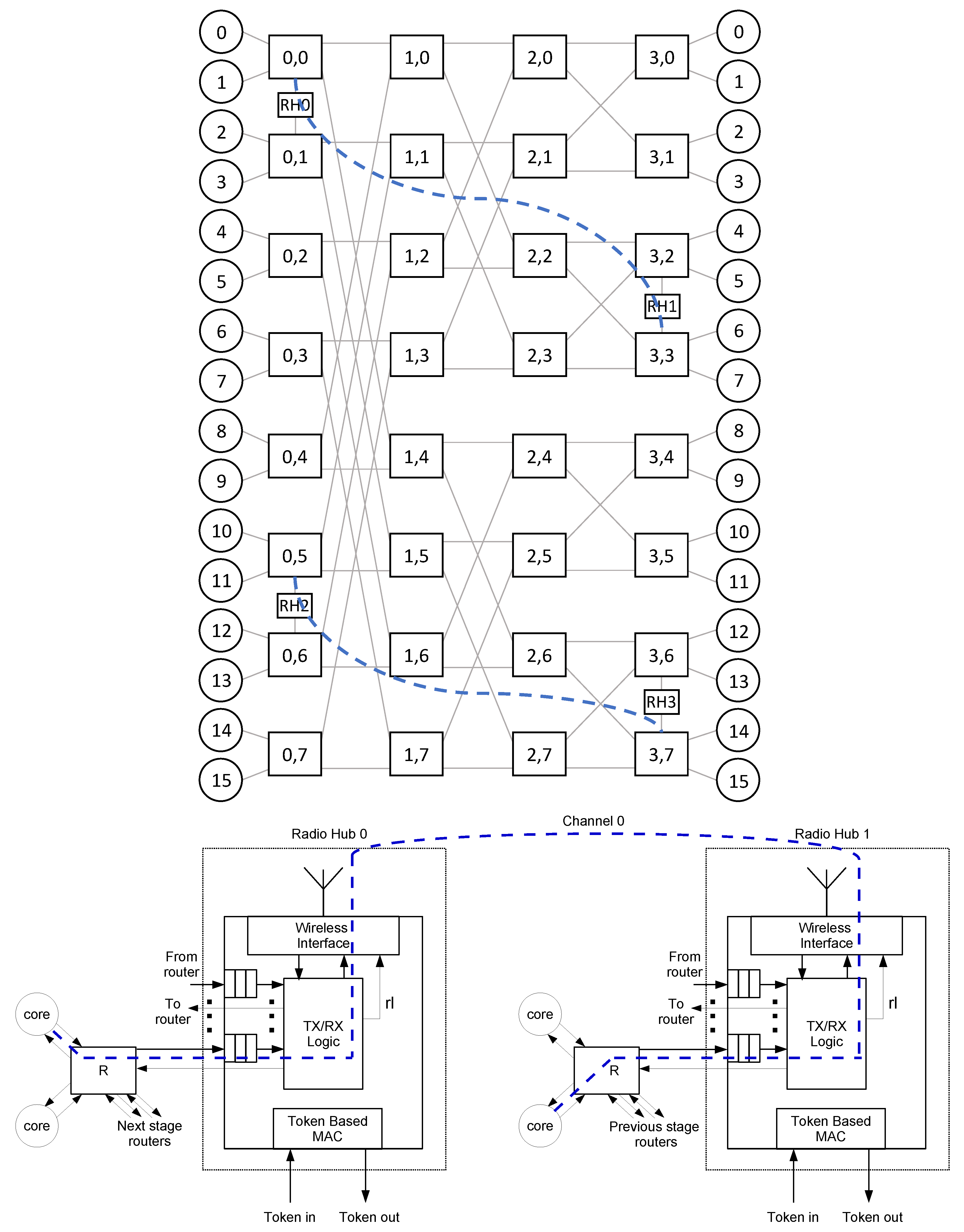
3.2. Wireless Radio-Hub

Once the new topology has been introduced the next required step was the implementation of a routing algorithm to enable wireless communications within the proposed Delta MINs architectures. Radio-hubs are switching nodes that allow for single hop communication between distant nodes that would require multiple hop communication in a wired fashion. A radio-hub can be connected with other non-radio switches through its wired ports, as shown in Figure 3. The communication among radio-hubs is based on radio channels in which access is regulated through a token-based medium access control (MAC) component [32]. In particular, a radio-hub can be physically able to use more than one channel, each of which is associated with a logical token ring. Every radio-hub that can transmit/receive through a channel is registered within the channel’s related token ring. To start a transmission through a specific channel, a radio-hub needs to wait for the related token.
The token is held until the end of a packet’s transmission, and then it is released and transferred to the next radio-hub of the token ring. If the radio-hub that receives a token does not have packets to transmit through the associated channel, the token is released and transferred to the next radio-hub of the token ring. In the implementation introduced in this work, a packet can be sent through a wireless hop at any stage of the proposed Delta MIN architecture.
It is important to notice that a radio-hub to radio-hub communication is a logical single-hop transmission, which can physically require several clock cycles to be performed. Indeed, assuming that a token is released only after the end of the transmission of a packet, the cycles needed to complete a single wireless transmission are:
N t r a n s m i s s i o n _ c y c l e s = T d e l a y × p a c k e t l e n g t h × c l o c k f r e q u e n c y
where packet length is expressed in the number of flits and T d e l a y is the amount of time required to transmit a flit, computed as:
T d e l a y = f l i t s i z e d a t a r a t e
given the data rate in bit/s of the antenna, and the flit size in bits.
If we consider a situation without congestion or conflicts in the allocation of resources (e.g., buffers), N t r a n s m i s s i o n _ c y c l e s is the minimum number of cycles to complete a wireless transmission, for a given configuration of packet length, flit size, clock frequency, and data rate. For example, given a configuration with a packet length of 8 flits, a flit size of 64 bits, a clock frequency of 1 GHz, and a mm-Wave antenna using On-Off keying (OOK) modulation with a data rate of 16 Gbps, we obtain a T d e l a y of 2 ns, for a N t r a n s m i s s i o n _ c y c l e s count of 32 cycles.
Technologies underlying the adopted on-chip radio communication are presented in [33,34,35] while [30] thoroughly details the radio-hub architecture.

3.3. Extension to Support Delta MINs Routing

One of the peculiarities of the Delta MINs is the simplicity of their routing algorithm, which employs the so-called destination tag routing technique. With this technique, the bits of the destination address are used immediately to route a packet, by determining the output port for each router at each stage of the network. In this way, only the knowledge of the destination address is required to make routing decisions.
The address of any core in a Delta MIN network is formed by l o g 2 N bits where N is the number of cores in the network. This, indeed, is the same formula to compute the number of stages. Considering networks with radix 2, upon reaching a switching node, one of the two output ports is selected based on the most significant bit (MSB) of the destination address. If that bit is zero, the up link (first output port) is selected, otherwise, the down link (second output port) is selected. Subsequently, before the packet leaves the switch, the destination address is shifted one bit to the left. The bit that has been used will be discarded and the next digit will be moved to the most significant position.
For instance, let us consider an 8-cores network with radix 2, such as the one depicted in Figure 1c, in which addresses are formed by 3 bits. Let us now consider a packet that has to be routed from the source core 2 to the destination core 6, this latter with binary address 110 2 . From core 2 the packet arrives to the switch R ( 0 , 1 ) . Then, R ( 0 , 1 ) consumes the MSB of destination address (1) and routes accordingly the packet through its port 1 linked to the switch R ( 1 , 3 ) . At this point R ( 1 , 3 ) consumes the new MSB (1) and routes accordingly the packet through its port 1 linked to the switch R ( 2 , 3 ) . Finally, R ( 2 , 3 ) consumes the MSB (the last bit remaining, 0) and delivers the packet accordingly through its port 0 connected to the designed destination, namely core 6.
From this example, it is clear that Delta MINs have a self-routing property in the sense that destination tag routing does not depend on the starting position but only on the destination address, which defines the output port chosen for each stage of switches. Hence, proceeding from any source towards the same destination, the identical 110 2 pattern of ports routes.

4. Evaluation and Results

This section presents the configuration proposed for the cycle-accurate assessment of Delta MIN, to evaluate the effects of the introduction of radio-hubs in the architecture, and comparing the same impact with the usage of traditional mesh based architectures. Also, the results related to a representative set of scenarios are discussed in SubSection 4.3.

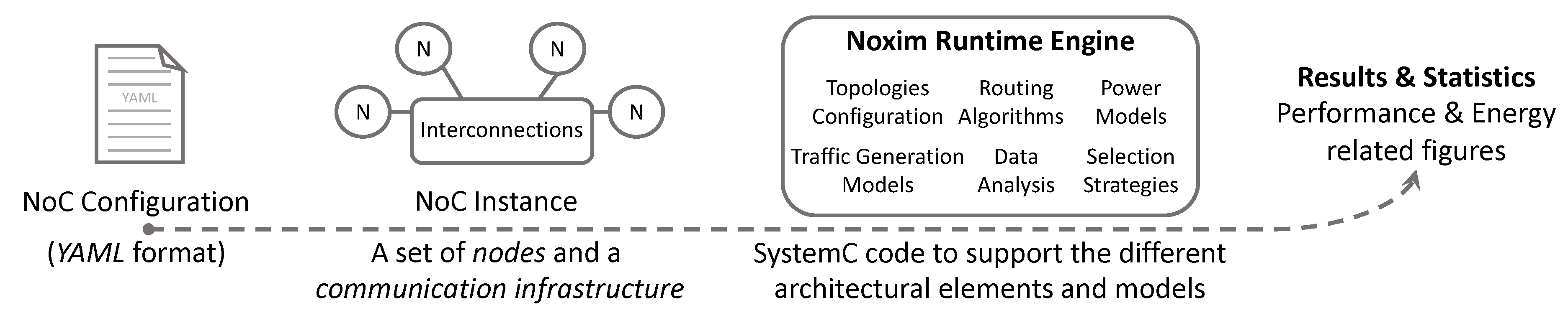
4.1. Noxim NoC Characterization

As aforementioned, to assess the proposed Delta MIN-based solution, we setup cycle-accurate simulations on Noxim [30], an open-source network-on-chip simulator that offers the tools to test radio-hubs within NoC architectures having a mesh topology. Figure 4 presents the simulation flow with Noxim. To instantiate a Network on Chip, a YAML configuration file, describing all the elements of the desired architecture, has to be prepared and passed as an input to Noxim. The resulting NoC instance, created by the simulator, consists of nodes and interconnections characterized by the properties specified in the configuration file (e.g., see Table 1). Then, the instance is evaluated by Noxim Runtime Engine (RE), which performs the required simulation through its SystemC-based libraries implementing the different NoC architectural elements and models. The result of each simulation is a report regarding performance figures such as throughput, latency, and delay.
The instance created by Noxim reproduces four essential characteristics of an NoC through their respective parameters. These characteristics are topology, traffic model, routing, and simulation. In particular, for what concerns topology, the set of parameters defines structural information, such as number and type of nodes (i.e., tiles, switches, radio-hubs), their interconnection details (e.g., wired or wireless link, its properties such as the latency), and the resulting shape of the NoC (e.g., which port is connected to which one). With regard to the traffic model, it is possible to set parameters such as packet length, packet injection rate (PIR), and the traffic type (e.g., table-based and random). Then, routing parameters determine at run-time, how components make decisions (e.g., routing algorithm). Finally, simulation parameters include reset time, warm-up time, and simulation duration.

4.2. Experimental Setup

Since a comprehensive assessment of all the possible design variations is beyond the scope of this work, we outlined in Table 1 the space of parameters for which we expect a default value not subjected to any further examination. Nevertheless, the proposed default values have been selected from those commonly used in the reference literature [21,30]. It is also important to outline that some of these parameters, for example, simulation time and number of repetitions are not tightly constrained to the modeled architecture but are essential to obtain statistically consistent results. In particular, for what concerns the network size, networks with 64, 256, and 1024 processing elements, respectively, have been tested. In Table 1, the network size parameter reports the number of cores (e.g., 64) and the dimensions of the matrix of switches in a Delta MIN with that number of cores (i.e., for a Delta MIN with 64 cores there are 32 switches per stage and 6 stages).
The metrics taken into account are:
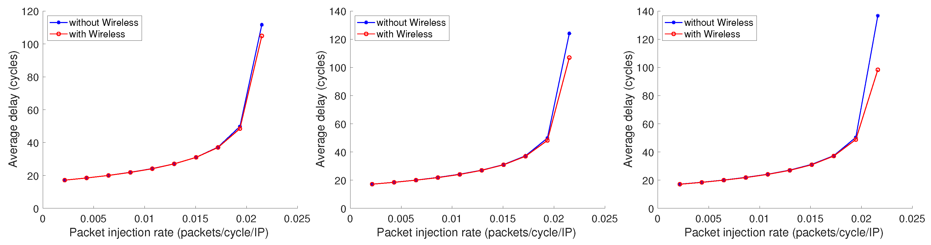
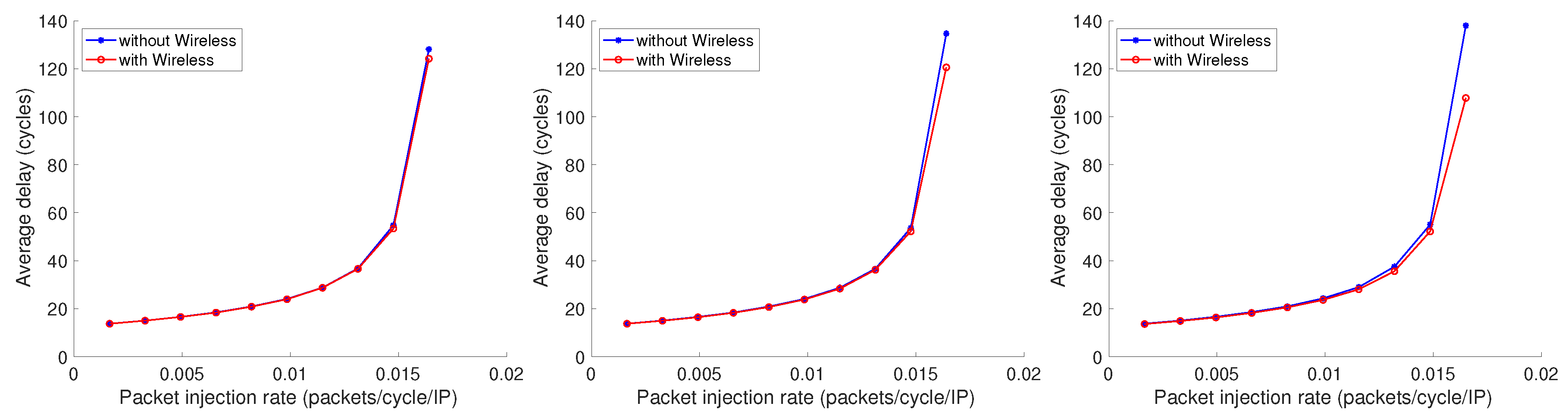
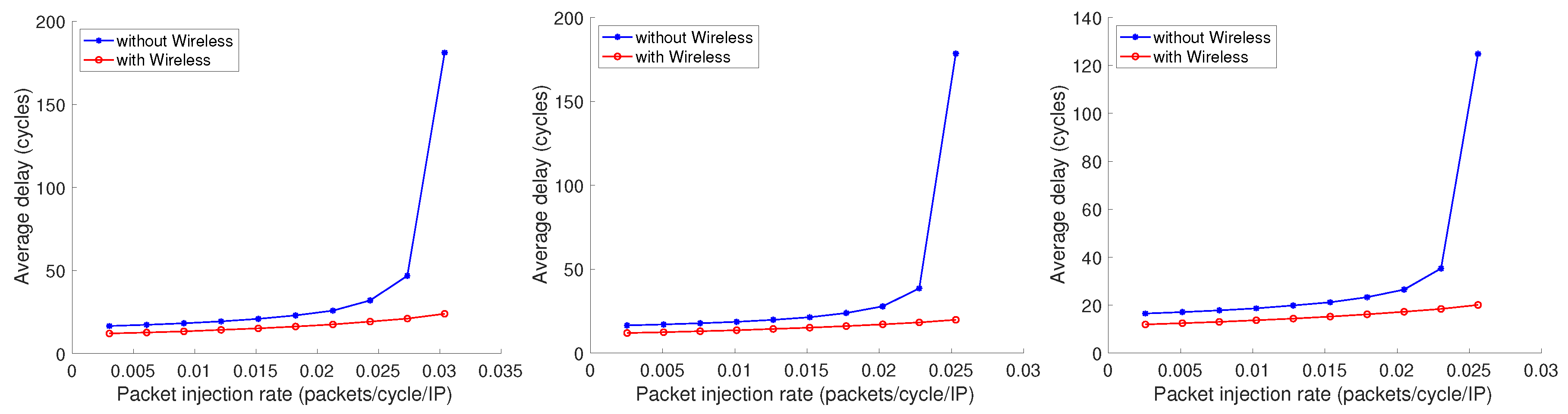
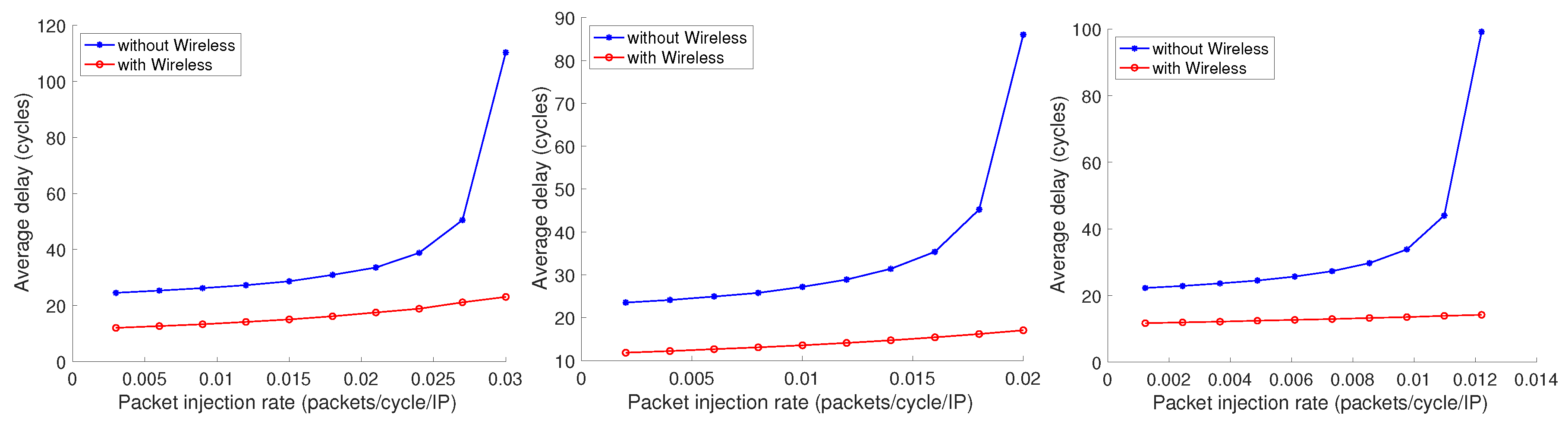
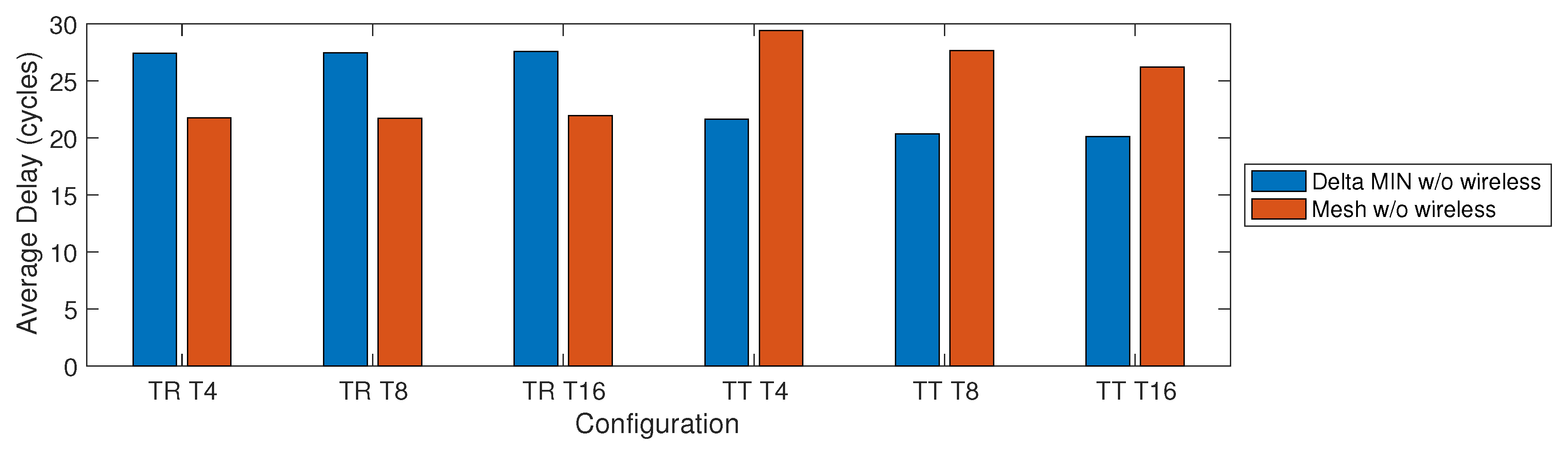
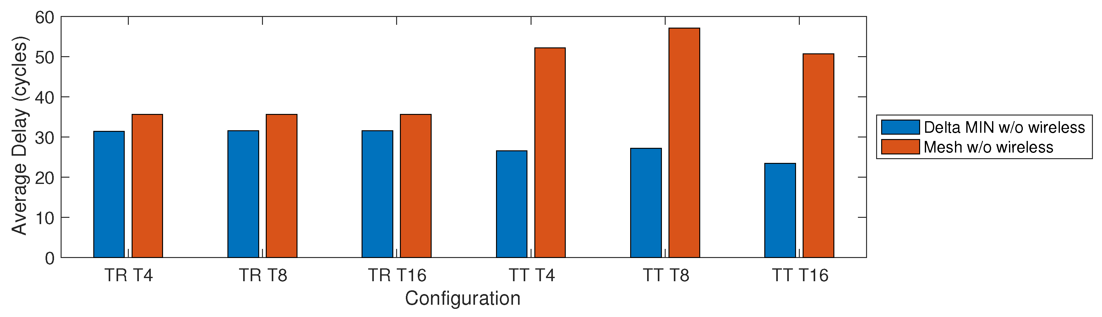
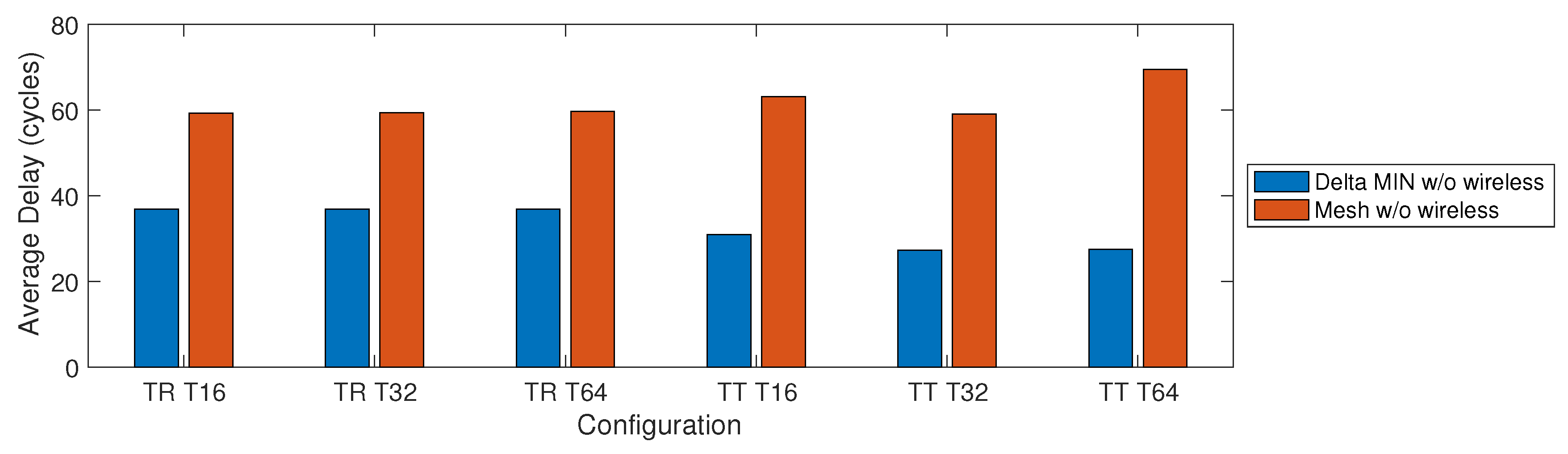
  • Latency: the average packet transmission latency in terms of clock cycles. Transmission latency is computed as the difference between the clock cycle in which the last bit of a packet arrived at the destination and the clock cycle in which the first bit of the packet left the source.
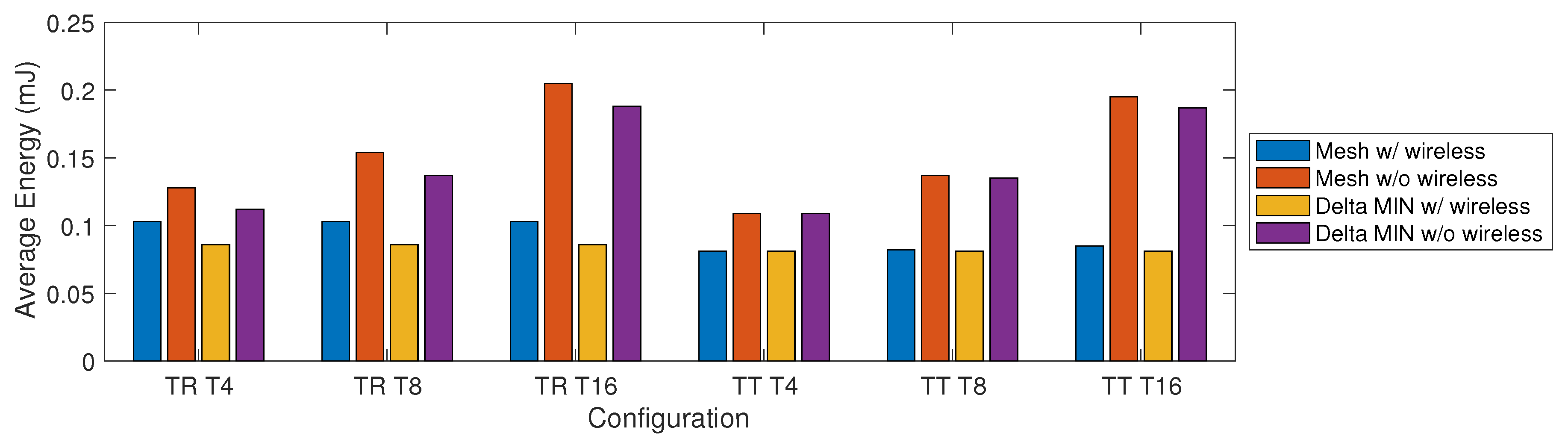
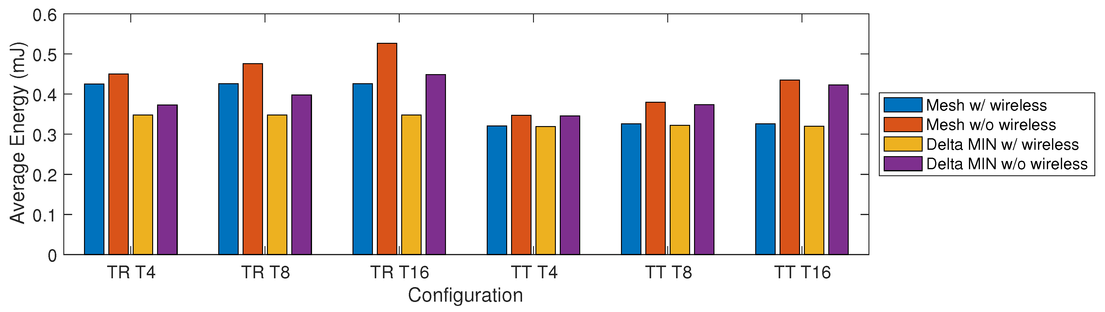
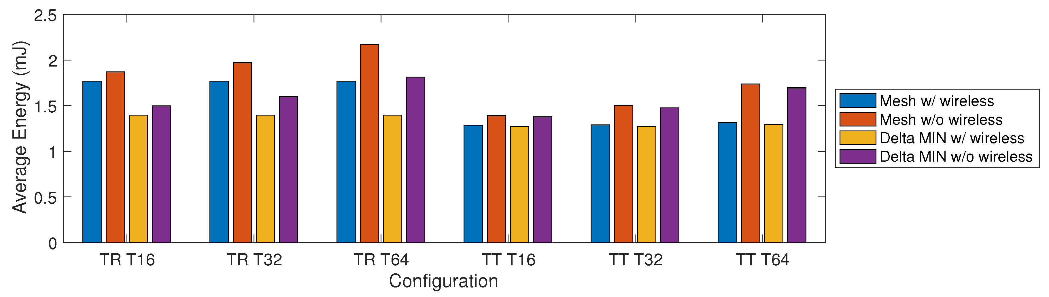
  • Energy consumption: the total energy consumption that includes routers, links, radio-hubs, and network-interfaces contributions. A more detailed description of the adopted energy models is available in [30].
To determine the effect of the incremental placement of radio-hubs into the architecture, a set of communication profiles have been taken into consideration. These profiles, namely T 4 , T 8 , T 16 , T 32 , and T 64 enable 4, 8, 16, 32, and 64 source/destination on-chip radio communication flows, respectively. For each of these source/destination pairs, there are two radio-hubs, the first connected to the source and the other to the destination, having a transmission channel in common. We assume that there is no interference among the channels, i.e., different communication flows do not share the same channels. This setup is simple but effective in the evaluation of the results of incremental insertion of radio-hubs in Delta MINs architectures.
The aforementioned communication profiles have been tested within two traffic scenarios:
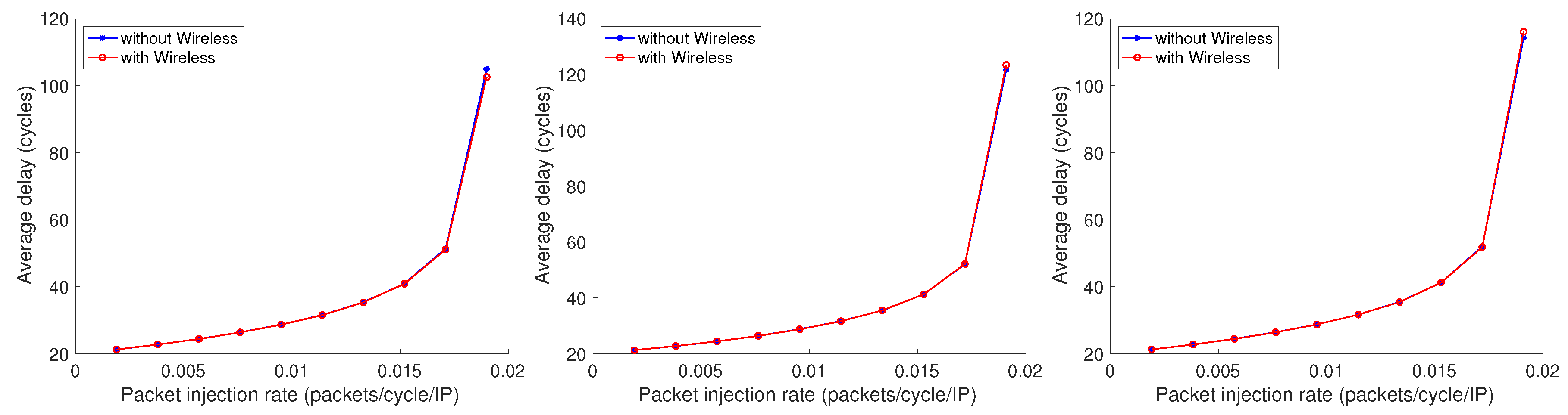
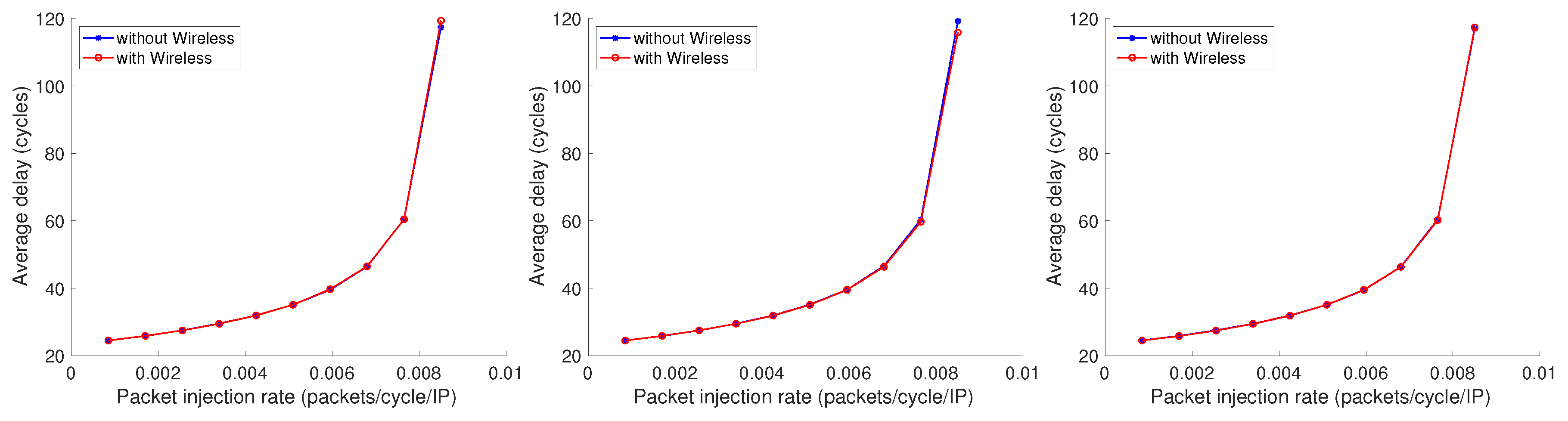
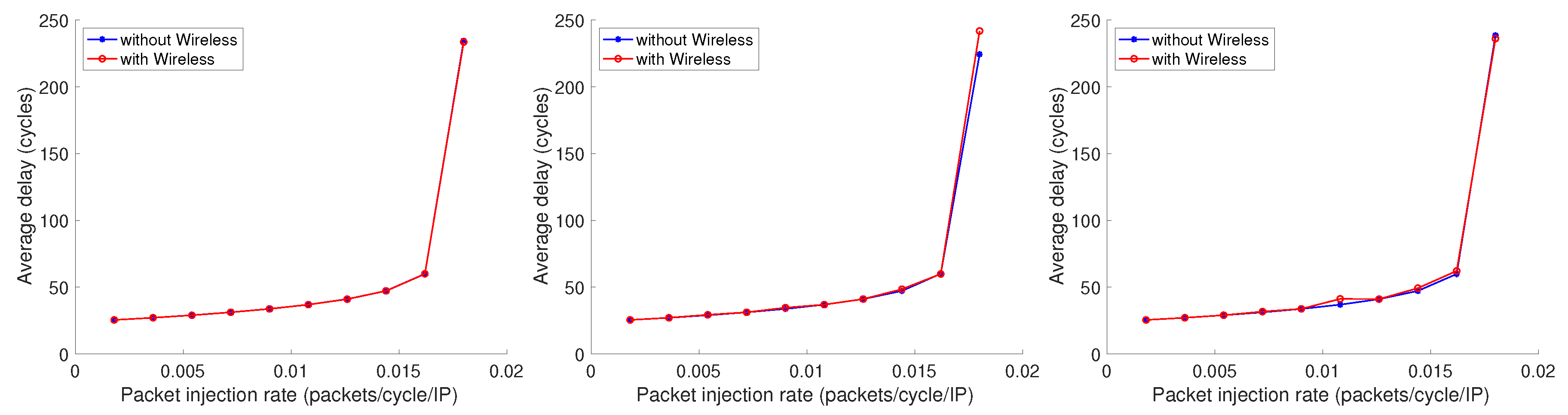
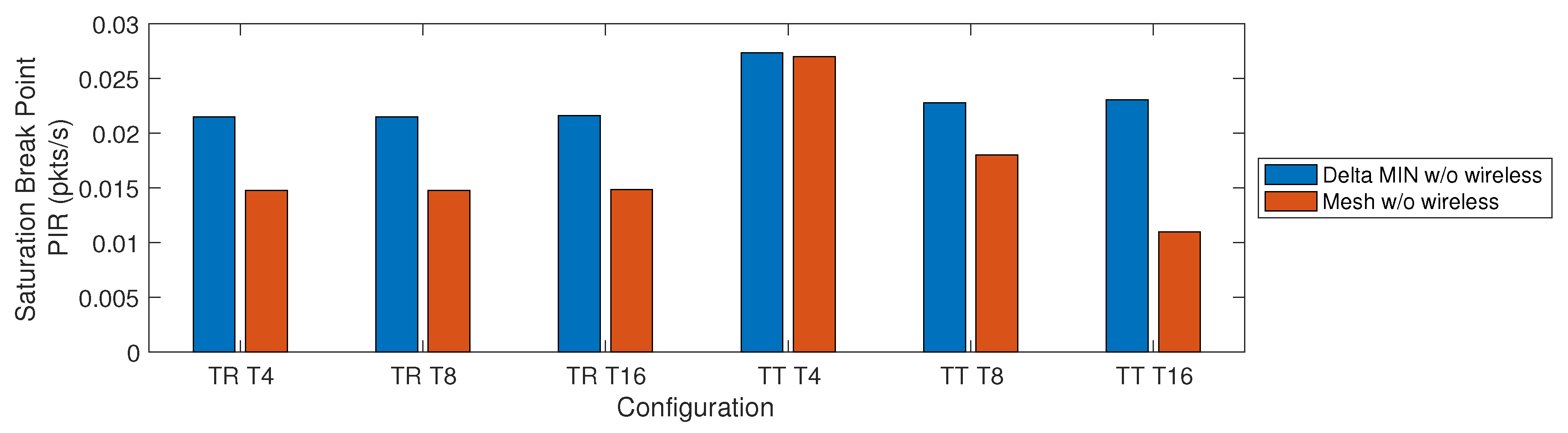
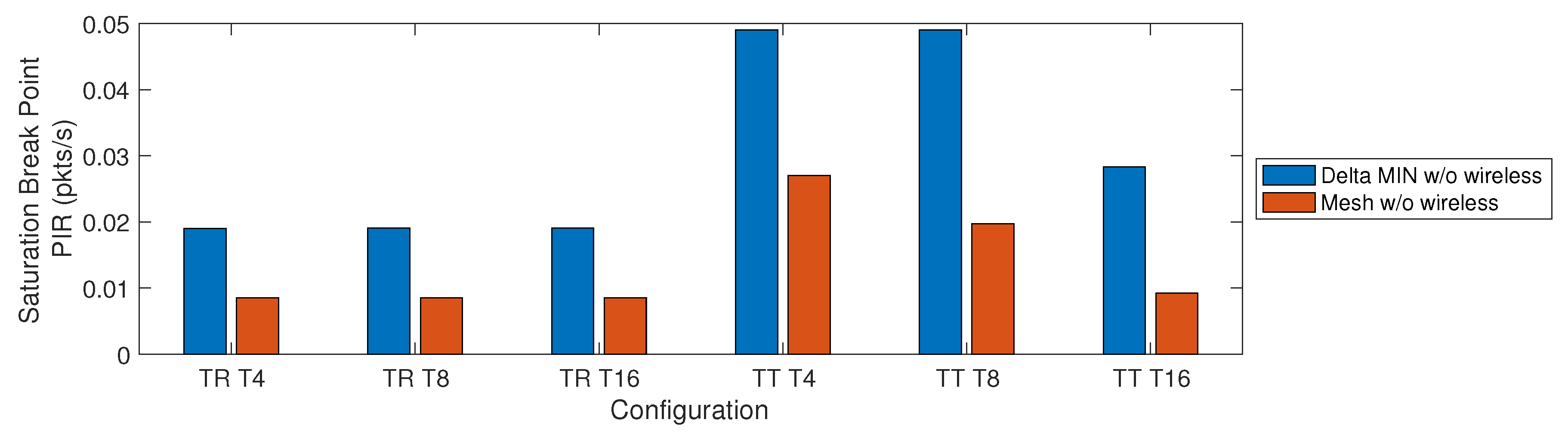
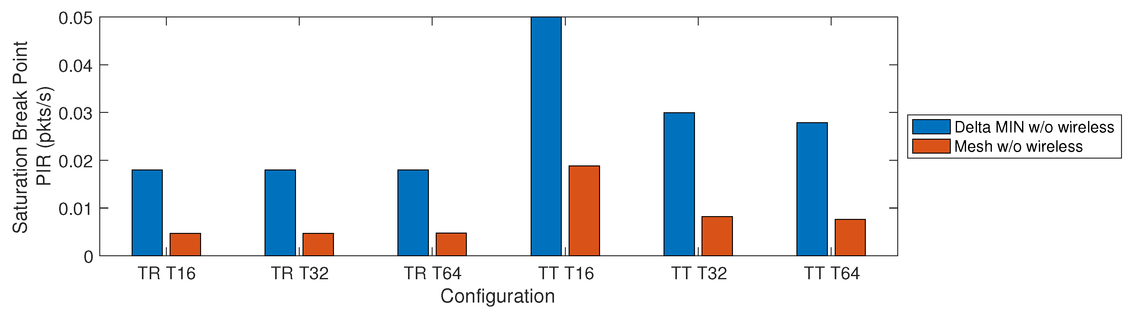
  • Traffic Random (TR): it is a scenario in which any node can send packets to any other node of the network (lack of specialization). Even if this scenario is synthetic, it provides a stress test to assess the impact of the introduction of radio on-chip communications for a set of nodes in a network in which there are no specialized nodes;
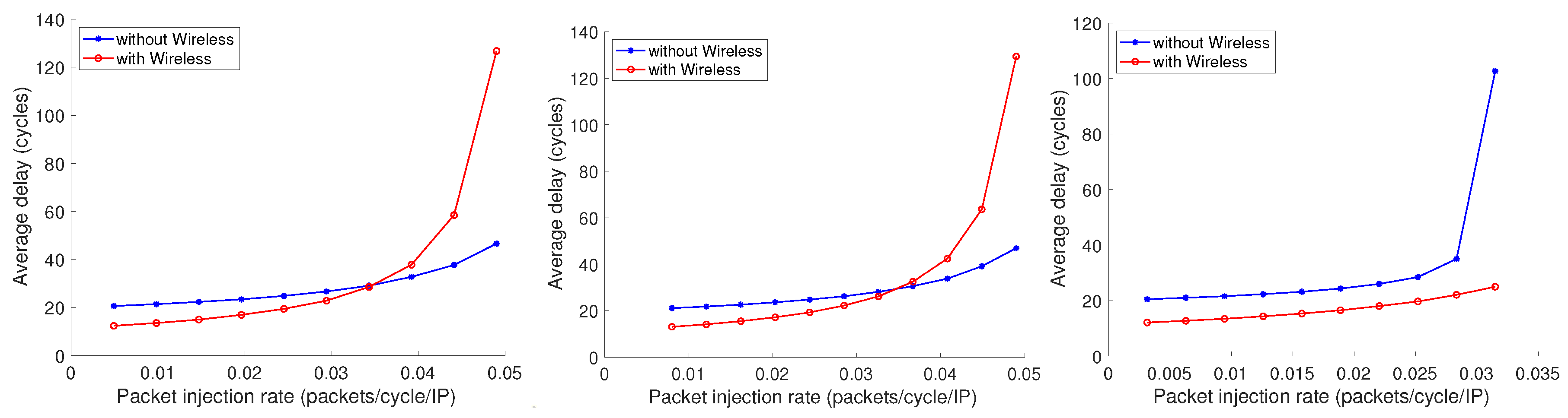
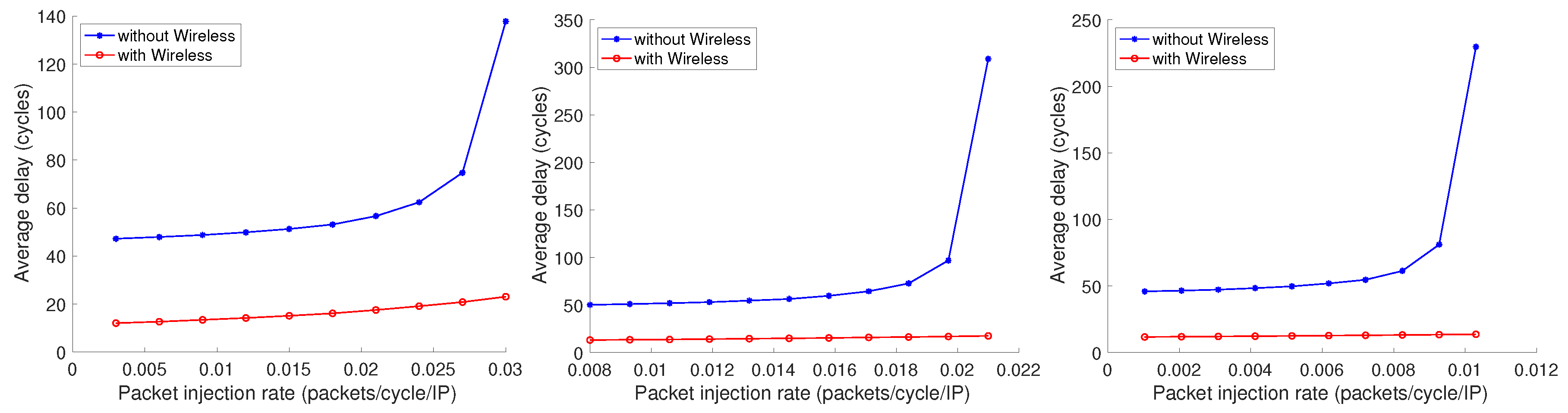
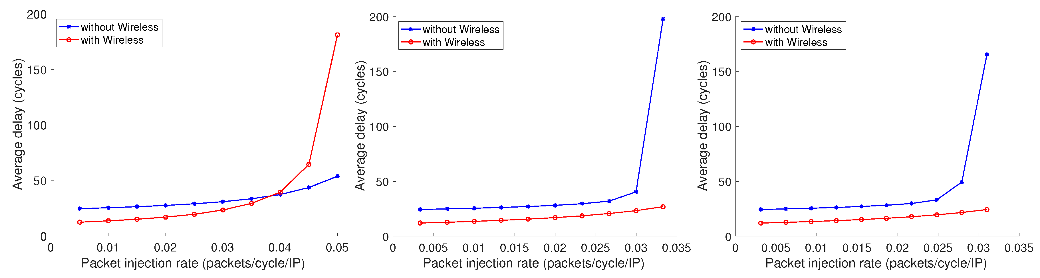
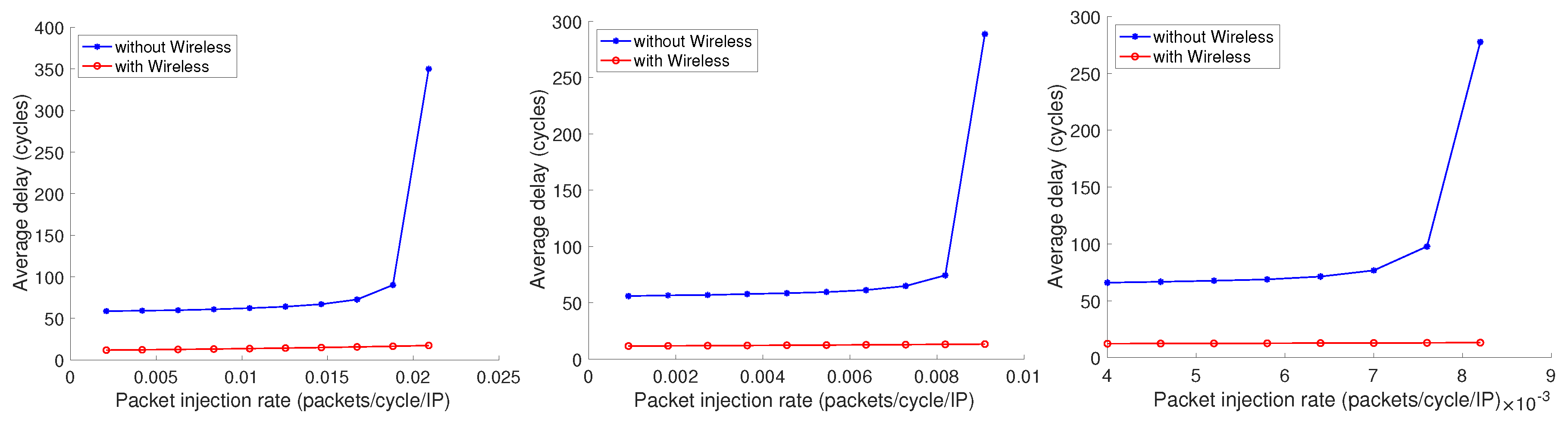
  • Traffic Table (TT): it is a scenario in which sources/destinations communication flows are described in a traffic table. Traffic tables can be recreated from traces of real applications, are representative of a more realistic traffic pattern in which a subset of communications between specific source/destination pairs is more intensive than the others. This may be the case, for example, of NoCs in which some nodes act as memory controllers, thus serving the memory read/write access requests coming from other nodes.
These traffic scenarios, in combination with the communication profiles, are then applied in the networks described by the space of parameters summarized in Table 1.

4.3. Results

Figure 5, Figure 6, Figure 7, Figure 8, Figure 9, Figure 10, Figure 11, Figure 12, Figure 13, Figure 14, Figure 15 and Figure 16 show the effect of incrementally adding multiple wireless communications flows, corresponding to the three communications profiles T 4 , T 8 , and T 16 ( T 16 , T 32 , and T 64 in the case of experiments with networks of 1024 nodes) described before. The analysis of the results can be conducted along with two different and orthogonal perspectives: ( i ) how Delta MINs perform as compared with traditional mesh architectures, ( i i ) how the wireless-augmented communication affects the average delay and saturation point for different traffic patterns and node number, regardless of the type of network.
For the sake of completeness and clarity, we also summarized numerically the main elements of the above figures in Table 2.
The first aspect of the results to be discussed is the effectiveness of the Delta MINs used as a reference architecture for implementing on-chip radio communication when compared to the traditional mesh-based architectures. In this case, the comparison should be made considering each couple of Delta MIN and Mesh results, for a fixed size and traffic pattern, and analyzing the packet injection rates at which saturation events occur.
For the sake of clarity, in addition to the figures mentioned above, the specific Figure 17, Figure 18, Figure 19, Figure 20, Figure 21 and Figure 22 show a direct comparison in terms of the saturation breakpoint and the average delay in non-saturated conditions. Observing the saturation breakpoint values reported in the first three Figure 17, Figure 18 and Figure 19, it is clear that, for a given network size and traffic scenario, saturation occurs at lower packet injection rates when mesh are being considered. This indicates a higher capacity of Delta MINs architectures to process the injected traffic. Also, this effect seems to be transversal, for example, not tied to the number of communication flows in the T T n traffic patterns. The next three Figure 20, Figure 21 and Figure 22 report the average delay in non-saturated conditions, essential to evaluate the network behavior in normal working conditions. Except for the first three bars of Figure 20, the delay of Delta MIN is far lower than the one reported for mesh topologies. Given the lower delay and higher saturation breakpoint of Delta MINs as compared to mesh, the potential positive impact of wireless communication results in an even more improved behavior.
When considering the results from the perspective of radio-hub usage impact, the experiments conducted show that in general, independently from the type of network topology considered, incremental usage of wireless communications mainly affects the saturation point, occurring at higher packet injection rates. However, the effect is more evident only when traffic table patterns are being considered, as in Figure 7 and Figure 8, and the other TT-n figures for 256 and 1024 nodes. Conversely, purely random traffic distributions (TR-n figures) seem to dilute the benefits of single point-to-point wireless communications, ranging from a slight improvement of saturation point (Figure 5 and Figure 6), to a negligible effect on bigger networks sizes (Figure 9, Figure 10, Figure 13, and Figure 14). As already discussed in the previous subsection, the random traffic distribution, although unrealistic, has been included to serve as an important worst-case scenario.
It should be also noticed that, in most profitable scenarios, such as bigger networks with T T traffic, using wireless communications not only improves the saturation point, but also the average delay in non-saturated conditions, as in Figure 11, Figure 12, Figure 15, and Figure 16. This can easily be explained when we consider that a major effect of using a direct communication between wireless radio-hubs is to replace several multi-hop wired transmissions with a single hop transmission. However, assuming a wired hop distance of d nodes between source and destination, the reduction ratio when replacing such a communication with wireless is not actually n. In fact, as also shown in Figure 3, there are some additional steps required, for example, for transmitting from the router to the radio-hub, and then, after the wireless transmission has been performed, to buffer the received flit in the local buffer of the receiving radio-hub. Needless to say, the same destination radio-hub will not be the actual destination, so a further step for transmitting the packet toward the final destination node will be required. Ignoring the additional potential delay effects caused by the congestion of internal radio-hub buffers, we can estimate that five hops are required to perform complete end-to-end wireless transmissions: two hops for router-to-radio-hub and radio-hub-to-antenna, on each side, and one hop for the radio transmission itself. In other words, even in the ideal case, there is an overhead to pay for replacing a multi-hop wired transmission with a wireless one, and we cannot expect to obtain any positive effect on delay when the average distance of the communications is below a certain threshold. This also explains why a relevant impact on average delay, even in non-saturated conditions, is found when considering the 256 and 1024 node sizes. The limitations discussed can be thus summarized as follows: ( i ) the network should large enough to counterbalance the overhead of introducing radio-hub hops ( i i ) the more the traffic is randomly distributed, the less will be the chance of replacing high-load wired communication flows with wireless communications, as already seen when discussing T R traffic patterns.
Finally, in Figure 23, Figure 24 and Figure 25 the average values for energy consumption in non-saturated conditions are visually reported, already shown in Table 2, but arranged by traffic patterns in six groups of four bars for each figure representing a given number of nodes. This allows us to separately evaluate the impact of enabling the wireless communication radio-hub modules and the impact of using Delta MINs networks as compared to traditional mesh. As it can be observed by considering a given network topology, for example, Mesh or Delta MIN, the usage of wireless radio-hubs results in an energy overhead, which is still acceptable and in the range of a 10%–15% bigger network (256 and 1024 nodes), but more consistent and relevant when a small 64 nodes network and more communication flows (e.g., 16) are being considered. This confirms that networks in which the size and average communication hops are below some threshold would not benefit from adding a wireless communication infrastructure. In other words, not only the improvement in terms of average delay and saturation breakpoint is limited when considering T R traffic patterns, but the energy overhead to pay is significant when a 64 network size is considered. As a consequence, smaller networks with a high randomly distributed traffic are the worst candidate for the replacement of wired multi-hop communications with a wireless radio-hub infrastructure.
Let us now analyze the same data from the perspective of a Mesh/Delta MINs comparison, being all the other aspects constant (e.g., network sizes and traffic patterns). We can observe that two rightmost bars (blue and orange) show higher energy values when compared to the corresponding two on the left (yellow and purple). Thus, a general effect of using Delta MINs is that of being, in general, more energy-efficient for the set of scenarios considered. This can be explained as a consequence of a general lower delay and higher saturation breakpoint already discussed above. However, it is worth noticing how the results of this effect are particularly relevant for the T R random traffic scenario, which we previously identified as the worst-case scenario for the usage of on-chip radio communications. As a consequence, we can deduct that, even when a non-ideal scenario for wireless communication is being considered, the same nature of Delta Multistage Interconnection Networks, by replacing the large amount of node-routers of Mesh architectures with shared switch-only nodes, still results in a appreciable energy efficiency, which will become more and more relevant with the increasing size in the number of cores of the future generations on-chip communication networks.

5. Conclusions

In this work, we propose and analyze the usage of the Delta Multistage Interconnection Network (MINs) as a backbone for wireless-enabled NoCs. Simulations performed with the cycle-accurate SystemC model demonstrate that wireless-augmented Delta MINs lead to an improvement in both average delay and saturation, with an energy overhead estimated between 5% and 20 % . Further, when compared to traditional mesh-based topologies, the energy profiles show that the overall energy cost is reduced on both wired/wireless scenarios. Future work will consider larger design spaces, where automatic strategies for ad-hoc fine-tuning of radio-hub features (e.g., ad-hoc buffer sizes and virtual channels) will be taken into consideration to optimize the performance/energy-overhead trade-off further. Another central perspective takes place to explore the benefits of Deep Neural Networks to perform energy estimation of Delta MINs.

Author Contributions

Conceptualization, S.M. (Sirine Mnejja) and D.P.; methodology, S.M. (Sirine Mnejja), D.P., S.M. (Salvatore Monteleone), and M.P.; software, S.M. (Sirine Mnejja), D.P., S.M. (Salvatore Monteleone), and M.P.; validation, Y.A., M.A., and V.C.; investigation, S.M. (Sirine Mnejja), D.P., and S.M. (Salvatore Monteleone); writing–original draft preparation, S.M. (Sirine Mnejja), D.P., and S.M. (Salvatore Monteleone); writing–review and editing, all the authors; visualization, S.M. (Sirine Mnejja) and S.M. (Salvatore Monteleone); supervision, D.P., Y.A., M.A., M.P. and V.C.; project administration, D.P., Y.A., M.A., and V.C.; funding acquisition, V.C., S.M. (Salvatore Monteleone), and M.P. All authors have read and agreed to the published version of the manuscript.

Funding

This work has been supported by the following institutions/grants: (i) the Italian Ministry of Economic Development (MISE) within the research program “UE-PON Imprese e Competitività 2014-2020 Contratto di sviluppo M9 (CDS 000448)” - CUP: C32F18000100008; (ii) the CY Advanced Studies Institute at the CY Cergy Paris Université (formerly Université de Cergy-Pontoise) under the Paris Seine Initiative for Excellence (“Investissements d’Avenir” ANR-16-IDEX-0008); (iii) the Department of Electrical, Electronic, and Computer Engineering (DIEEI) at University of Catania within the research program “Piano per la Ricerca 2016/2018”.

Conflicts of Interest

The authors declare no conflict of interest. The funders had no role in the design of the study; in the collection, analyses, or interpretation of data; in the writing of the manuscript, or in the decision to publish the results.

References

  1. Banerjee, N.; Vellanki, P.; Chatha, K.S. A power and performance model for network-on-chip architectures. In Proceedings of the conference on Design, automation and test in Europe-Volume 2, IEEE Computer Society, Paris, France, 16–20 February 2004; IEEE: Piscataway, NJ, USA, 2004; p. 21250. [Google Scholar]
  2. Biberman, A.; Preston, K.; Hendry, G.; Sherwood-Droz, N.; Chan, J.; Levy, J.S.; Lipson, M.; Bergman, K. Photonic network-on-chip architectures using multilayer deposited silicon materials for high-performance chip multiprocessors. ACM J. Emerg. Technol. Comput. Syst. (JETC) 2011, 7, 7. [Google Scholar] [CrossRef]
  3. Yang, L.; Liu, W.; Jiang, W.; Li, M.; Yi, J.; Sha, E.H.M. Application mapping and scheduling for network-on-chip-based multiprocessor system-on-chip with fine-grain communication optimization. IEEE Trans. Very Large Scale Integr. (VLSI) Syst. 2016, 24, 3027–3040. [Google Scholar] [CrossRef]
  4. Pande, P.P.; Grecu, C.; Jones, M.; Ivanov, A.; Saleh, R. Performance evaluation and design trade-offs for network-on-chip interconnect architectures. IEEE Trans. Comput. 2005, 54, 1025–1040. [Google Scholar] [CrossRef]
  5. Ogras, U.Y.; Bogdan, P.; Marculescu, R. An analytical approach for network-on-chip performance analysis. IEEE Trans. Comput. Aided Des. Integr. Circuits and Syst. 2010, 29, 2001–2013. [Google Scholar] [CrossRef]
  6. Chang, K.; Deb, S.; Ganguly, A.; Yu, X.; Sah, S.P.; Pande, P.P.; Belzer, B.; Heo, D. Performance evaluation and design trade-offs for wireless network-on-chip architectures. ACM J. Emerg. Technol. Comput. Syst. (JETC) 2012, 8, 23. [Google Scholar] [CrossRef]
  7. Bononi, L.; Concer, N. Simulation and analysis of network on chip architectures: ring, spidergon and 2D mesh. In Proceedings of the Conference on Design, Automation and Test in Europe: Designers’ Forum, Munich, Germany, 6–10 March 2006; European Design and Automation Association, ACM: New York, NY, USA, 2006; pp. 154–159. [Google Scholar]
  8. Agarwal, A.; Iskander, C.; Shankar, R. Survey of network on chip (noc) architectures & contributions. J. Eng. Comput. Archit. 2009, 3, 21–27. [Google Scholar]
  9. Chen, J.; Li, C.; Gillard, P. Network-on-chip (NoC) topologies and performance: A review. In Proceedings of the 2011 Newfoundland Electrical and Computer Engineering Conference (NECEC), St. John’s, Canada, 1 November 2011; pp. 1–6. [Google Scholar]
  10. Ansari, A.Q.; Ansari, M.R.; Khan, M.A. Performance evaluation of various parameters of network-on-chip (noc) for different topologies. In Proceedings of the Annual IEEE India Conference (INDICON), New Delhi, India, 17–20 December 2015; IEEE: Piscataway, NJ, USA, 2015; pp. 1–4. [Google Scholar]
  11. Aydi, Y.; Meftali, S.; Dekeyser, J.L.; Abid, M. Design and performance evaluation of a reconfigurable delta MIN for MPSOC. In Proceedings of the Internatonal Conference on Microelectronics, Cairo, Egypt, 29–31 December 2007; IEEE: Piscataway, NJ, USA, 2007; pp. 115–118. [Google Scholar]
  12. Bhardwaj, V.P.; Chauhan, P.; Indian Institute of Management Mayurbhanj Complex. On Analysis and Discussion of Various Performance Parameters of Omega and Advance Omega Interconnection Network. In Proceedings of the 4th International Conference on Computing Communication and Automation (ICCCA), Greater Noida, India, 14–15 December 2018; IEEE: Piscataway, NJ, USA, 2018; pp. 1–4. [Google Scholar]
  13. Kruskal, C.P.; Snir, M. A unified theory of interconnection network structure. Theor. Comput. Sci. 1986, 48, 75–94. [Google Scholar] [CrossRef] [Green Version]
  14. Zhao, D.; Wang, Y. SD-MAC: Design and Synthesis of a Hardware-Efficient Collision-Free QoS-Aware MAC Protocol for Wireless Network-on-Chip. IEEE Trans. Comput. 2008, 57, 1230–1245. [Google Scholar] [CrossRef]
  15. Mnejja, S.; Aydi, Y.; Abid, M.; Monteleone, S.; Palesi, M.; Patti, D. Implementing On-Chip Wireless Communication in Multi-stage Interconnection NoCs. In Proceedings of the International Conference on Advanced Information Networking and Applications, Caserta, Italy, 15–17 April 2020; Springer: Cham, Switzerland, 2020; pp. 533–546. [Google Scholar]
  16. Yunus, N.A.M.; Othman, M.; Hanapi, Z.M.; Lun, K.Y. Reliability Review of Interconnection Networks. IETE Tech. Rev. 2016, 33, 596–606. [Google Scholar] [CrossRef]
  17. Rajkumar, S.; Goyal, N.K. Review of Multistage Interconnection Networks Reliability and Fault-Tolerance. IETE Tech. Rev. 2016, 33, 223–230. [Google Scholar] [CrossRef]
  18. Achballah, A.B.; Othman, S.B.; Saoud, S.B. Problems and challenges of emerging technology networks- on- chip: A review. Microprocess. Microsyst. 2017, 53, 1–20. [Google Scholar] [CrossRef]
  19. Pande, P.P.; Kim, R.G.; Choi, W.; Chen, Z.; Marculescu, D.; Marculescu, R. The (low) power of less wiring: Enabling energy efficiency in many-core platforms through wireless noc. In Proceedings of the IEEE/ACM International Conference on Computer-Aided Design, Austin, TX, USA, 2–6 November 2015; IEEE: Piscataway, NJ, USA, 2015; pp. 165–169. [Google Scholar]
  20. Kim, R.G.; Choi, W.; Chen, Z.; Pande, P.P.; Marculescu, D.; Marculescu, R. Wireless NoC and dynamic VFI codesign: Energy efficiency without performance penalty. IEEE Trans. Very Large Scale Integr. (VLSI) Syst. 2016, 24, 2488–2501. [Google Scholar] [CrossRef]
  21. Catania, V.; Mineo, A.; Monteleone, S.; Palesi, M.; Patti, D. Improving energy efficiency in wireless network-on-chip architectures. ACM J. Emerg. Technol. Comput. Syst. (JETC) 2018, 14, 9. [Google Scholar] [CrossRef] [Green Version]
  22. Catania, V.; Mineo, A.; Monteleone, S.; Palesi, M.; Patti, D. Energy efficient transceiver in wireless network on chip architectures. In Proceedings of the 2016 Conference on Design, Automation & Test in Europe, EDA Consortium, Dresden, Germany, 14–18 March 2016; ACM: New York, NY, USA, 2016; pp. 1321–1326. [Google Scholar]
  23. Dai, P.; Chen, J.; Zhao, Y.; Lai, Y.H. A Study of a Wire-wireless Hybrid NoC Architecture with an Energy-proportional Multicast Scheme for Energy Efficiency. Comput. Electr. Eng. 2015, 45, 402–416. [Google Scholar] [CrossRef]
  24. Tavakoli, E.; Tabandeh, M.; Kaffash, S.; Raahemi, B. Multi-hop Communications on Wireless Network-on-chip Using Optimized Phased-array Antennas. Comput. Electr. Eng. 2013, 39, 2068–2085. [Google Scholar] [CrossRef]
  25. Zhao, D.; Wang, Y.; Li, J.; Kikkawa, T. Design of multi-channel wireless NoC to improve on-chip communication capacity! In Proceedings of the Fifth ACM/IEEE International Symposium, Pittsburgh, PA, USA, 1–4 May 2011; pp. 177–184. [Google Scholar]
  26. Wang, C.; Hu, W.H.; Bagherzadeh, N. A wireless network-on-chip design for multicore platforms. In Proceedings of the 19th International Euromicro Conference on Parallel, Distributed and Network-Based Processing, Ayia Napa, Cyprus, 9–11 February 2011; IEEE: Piscataway, NJ, USA, 2011; pp. 409–416. [Google Scholar]
  27. Lee, S.B.; Tam, S.W.; Pefkianakis, I.; Lu, S.; Chang, M.F.; Guo, C.; Reinman, G.; Peng, C.; Naik, M.; Zhang, L.; et al. A scalable micro wireless interconnect structure for CMPs. In Proceedings of the 15th Annual International Conference on Mobile Computing and Networking, ACM, Beijing China, 20–25 September 2009; pp. 217–228. [Google Scholar]
  28. Wu, R.; Wang, Y.; Zhao, D. A low-cost deadlock-free design of minimal-table rerouted xy-routing for irregular wireless nocs. In Proceedings of the Fourth ACM/IEEE International Symposium on Networks-on-Chip, Grenoble, France, 3–6 May 2010; pp. 199–206. [Google Scholar]
  29. He, R.; Delgado-Frias, J.G. Fault Tolerant Interleaved Switching Fabrics For Scalable High-Performance Routers. IEEE Trans. Parallel Distrib. Syst. 2007, 18, 1727–1739. [Google Scholar] [CrossRef]
  30. Catania, V.; Mineo, A.; Monteleone, S.; Palesi, M.; Patti, D. Cycle-Accurate Network on Chip Simulation with Noxim. ACM Trans. Model. Comput. Simul. (TOMACS) 2016, 27, 4:1–4:25. [Google Scholar] [CrossRef]
  31. Palesi, M.; Patti, D.; Fazzino, F.; Monteleone, S. GitHub, Noxim—The NoC Simulator. 2019. Available online: https://github.com/davidepatti/noxim (accessed on 18 May 2020).
  32. Palesi, M.; Collotta, M.; Mineo, A.; Catania, V. An Efficient Radio Access Control Mechanism for Wireless Network-on-Chip Architectures. J. Low Power Electr. Appl. 2015, 5, 38–56. [Google Scholar] [CrossRef] [Green Version]
  33. Abadal, S.; Alarcón, E.; Cabellos-Aparicio, A.; Lemme, M.C.; Nemirovsky, M. Graphene-enabled wireless communication for massive multicore architectures. IEEE Commun. Mag. 2013, 51, 137–143. [Google Scholar] [CrossRef]
  34. Vien, Q.T.; Agyeman, M.O.; Le, T.A.; Mak, T. On the nanocommunications at THz band in graphene-enabled wireless network-on-chip. Math. Problems Eng. 2017, 2017, 1–13. [Google Scholar] [CrossRef]
  35. Abadal, S.; Hosseininejad, S.E.; Cabellos-Aparicio, A.; Alarcón, E. Graphene-based terahertz antennas for area-constrained applications. In Proceedings of the 40th International Conference on Telecommunications and Signal Processing (TSP), Barcelona, Spain, 5–7 July 2017; IEEE: Piscataway, NJ, USA, 2017; pp. 817–820. [Google Scholar]
  36. Mohapatra, P. Wormhole routing techniques for directly connected multicomputer systems. ACM Comput. Surv. 1998, 30, 374–410. [Google Scholar] [CrossRef]
Figure 1. Interconnection in Mesh architectures (a); Processing Elements (PE) and Switches’ interconnection in a Delta Multistage Interconnection Network (MIN) (b); an example Delta MIN with 8 core nodes (c).
Electronics 09 00913 g001
Figure 2. Average hop distance in Delta MIN topologies and Mesh topologies for an increasing number of cores.
Electronics 09 00913 g002
Figure 3. Delta MIN with 16 cores augmented with 4 radio-hubs. Detail of the end-to-end communication by means of two radio-hubs sharing a wireless channel connected to switches in the first and last stage.
Electronics 09 00913 g003
Figure 4. Cycle-accurate Noxim-based design flow.
Electronics 09 00913 g004
Figure 5. From left to right: Average delay for profiles T 4 , T 8 , and T 16 for 64 Delta MIN topology and random traffic (TR-64 Delta MIN).
Electronics 09 00913 g005
Figure 6. From left to right: Average delay for profiles T 4 , T 8 , and T 16 for 64 Mesh topology and random traffic (TR-64 Mesh).
Electronics 09 00913 g006
Figure 7. From left to right: Average delay for profiles T 4 , T 8 , and T 16 for 64 Delta MIN topology and table-based traffic (TT-64 Delta MIN).
Electronics 09 00913 g007
Figure 8. From left to right: Average delay for profiles T 4 , T 8 , and T 16 for 64 Mesh scenario and table-based traffic (TT-64 Mesh).
Electronics 09 00913 g008
Figure 9. Average delay for profiles T 4 , T 8 , and T 16 for 256 Delta MIN topology and random traffic (TR-256 Delta MIN).
Electronics 09 00913 g009
Figure 10. Average delay for profiles T 4 , T 8 , and T 16 for 256 Mesh topology and random traffic (TR-256 Mesh).
Electronics 09 00913 g010
Figure 11. Average delay for profiles T 4 , T 8 , and T 16 for 256 Delta MIN topology and table-based traffic (TT-256 Delta MIN).
Electronics 09 00913 g011
Figure 12. Average delay for profiles T 4 , T 8 , and T 16 for 256 Mesh topology and table-based traffic (TT-256 Mesh).
Electronics 09 00913 g012
Figure 13. Average delay for profiles T 16 , T 32 , and T 64 for 1024 Delta MIN topology and random traffic (TR-1024 Delta MIN).
Electronics 09 00913 g013
Figure 14. Average delay for profiles T 16 , T 32 , and T 64 for 1024 Mesh topology and random traffic (TR-1024 Mesh).
Electronics 09 00913 g014
Figure 15. Average delay for profiles T 16 , T 32 , and T 64 for 1024 Delta MIN topology and table-based traffic (TT-1024 Delta MIN).
Electronics 09 00913 g015
Figure 16. Average delay for profiles T 16 , T 32 , and T 64 1024 Mesh topology and table-based traffic (TT-1024 Mesh).
Electronics 09 00913 g016
Figure 17. Saturation break point packet injection rate (PIR) (pkts/s) for Delta MIN and mesh topologies of size 64.
Electronics 09 00913 g017
Figure 18. Saturation break point PIR (pkts/s) for Delta MIN and mesh topologies of size 256.
Electronics 09 00913 g018
Figure 19. Saturation break point PIR (pkts/s) for Delta MIN and mesh topologies of size 1024.
Electronics 09 00913 g019
Figure 20. Average delay (cycles) in non-saturated conditions for Delta MIN and mesh topologies of size 64.
Electronics 09 00913 g020
Figure 21. Average delay (cycles) in non-saturated conditions for Delta MIN and mesh topologies of size 256.
Electronics 09 00913 g021
Figure 22. Average delay (cycles) in non-saturated conditions for Delta MIN and mesh topologies of size 1024.
Electronics 09 00913 g022
Figure 23. Average energy (mJ) in non-saturated conditions for Delta MIN and mesh topologies of size 64.
Electronics 09 00913 g023
Figure 24. Average energy (mJ) in non-saturated conditions for Delta MIN and mesh topologies of size 256.
Electronics 09 00913 g024
Figure 25. Average energy (mJ) in non-saturated conditions for Delta MIN and mesh topologies of size 1024.
Electronics 09 00913 g025
Table 1. Simulation parameter space.
ParameterValue
Network size [cores/(switches × stages)]64/ ( 32 × 6 ) , 256/ ( 128 × 8 ) , 1024/ ( 512 × 10 )
64/256 radio-hubs number4, 8, 16
1024 radio-hubs number16, 32, 64
Switching techniqueWormhole [36]
Radio Access Control MechanismToken Packet [32]
Wireless data rate [Gbps]16
Packet length [flit]8
Flit size [bit]64
Router input buffer size [flit]4
Radio-hub input, antenna buffer size [flit]4
Simulation Time100,000 cycles
Repetitions10
Table 2. Summary of results obtained in the different scenarios presented in Figure 5, Figure 6, Figure 7, Figure 8, Figure 9, Figure 10, Figure 11, Figure 12, Figure 13, Figure 14, Figure 15 and Figure 16.
Without WirelessWith Wireless
SizeTopologyTrafficSaturation Break
Point PIR (pkts/s)
Avg Delay (Cycles)
(Before Saturation)
Avg Energy (mJ)
(Before Saturation)
Saturation Break
Point PIR (pkts/s)
Avg Delay (Cycles)
(Before Saturation)
Avg Energy (mJ)
(Before Saturation)
64Delta MINTR T 4 0.0215027.4370.1030.0215027.2560.128
TR T 8 0.0215027.4620.1030.0215027.1830.154
TR T 16 0.0216027.5660.1030.0216027.2710.205
TT T 4 0.0273621.6610.0810.0456016.5710.109
TT T 8 0.0227720.3620.0820.0480715.1890.137
TT T 16 0.0230420.1190.0850.0486415.2680.195
64MeshTR T 4 0.0147621.7760.0860.0147621.6990.112
TR T 8 0.0147621.7430.0860.0147621.5400.137
TR T 16 0.0148521.9560.0860.0148521.3420.188
TT T 4 0.0270029.4260.0810.0480016.4120.109
TT T 8 0.0180027.6570.0810.0480014.0930.135
TT T 16 0.0109826.2340.0810.0488012.8750.187
256Delta MINTR T 4 0.0190031.4090.4250.0190031.3660.450
TR T 8 0.0191031.5690.4260.0191031.5700.476
TR T 16 0.0191031.5460.4260.0191031.5190.527
TT T 4 0.0490026.5320.3210.0441020.8090.347
TT T 8 0.0490027.1790.3260.0449022.5050.380
TT T 16 0.0283523.4070.3260.0472516.9070.435
256MeshTR T 4 0.0085035.6290.3480.0085035.6410.373
TR T 8 0.0085035.6330.3480.0085035.5180.398
TR T 16 0.0085035.6030.3480.0085035.5540.449
TT T 4 0.0270052.1500.3190.0480016.3900.346
TT T 8 0.0197057.0610.3220.0484015.0540.374
TT T 16 0.0092750.7010.3200.0484112.6240.423
1024Delta MINTR T 16 0.0180036.8341.7690.0180036.8381.870
TR T 32 0.0180036.8531.7690.0180037.1081.971
TR T 64 0.0180036.8221.7690.0180037.8412.174
TT T 16 0.0500030.9391.2870.0450021.2481.390
TT T 32 0.0299727.2741.2910.0499517.5381.504
TT T 64 0.0279027.4631.3140.0496016.7471.737
1024MeshTR T 16 0.0047059.3041.3970.0047059.2581.499
TR T 32 0.0047159.4151.3980.0047159.4331.600
TR T 64 0.0047359.6371.3980.0473059.7521.813
TT T 16 0.0188163.1411.2750.0480714.2761.377
TT T 32 0.0081959.0121.2730.0482312.4741.477
TT T 64 0.0076069.5161.2920.0484012.6881.695

