A Study on Precise Positioning for an Electric Vehicle Wireless Power Transfer System Using a Ferrite Antenna


Department of Electronics and Computer Engineering, Hanyang University, Seoul 04763, Korea
*
Author to whom correspondence should be addressed.
Electronics 2020, 9(8), 1289; https://0-doi-org.brum.beds.ac.uk/10.3390/electronics9081289
Submission received: 7 June 2020
/
Revised: 4 August 2020
/
Accepted: 7 August 2020
/
Published: 11 August 2020
(This article belongs to the Special Issue Wireless Power/Data Transfer, Energy Harvesting System Design)
Abstract
:In the last decade, engineers from automotive manufacturers and charging infrastructure suppliers have widely studied the application of wireless power transfer (WPT) technology to electric vehicles. Since this time, engineers from automotive manufacturers have studied precise positioning methods suitable for WPT using methods such as mechanical, communication-based or video-based. However, due to high costs, electromagnetic interference and environmental factors, the experts of the SAE J2954 was focused on the WPT’s precise positioning method by ferrite antennas and low power excitation. In this study, we present how to use the ferrite antennas to find a central alignment point between the primary and secondary units within the alignment tolerance area that requires the minimum power transfer efficiency of the EV WPT system. First, we analyze the ferrite antenna already applied in the automotive and verifies whether it is suitable for the precise positioning of the WPT system for EV. We use modeling and simulation to show that it is necessary to calculate all induced loop voltages in the relationship between incident magnetic field signal strength and induced loop voltage because of the short distance between the transmitter and receiver of the ferrite antenna in WPT. In addition, we also suggest a sequence to find the fitting location of the ferrite antenna, the number of antennas used and the center alignment point. After the simulation is performed on the suggestions, component-level and vehicle-level tests were conducted to verify the validity of the simulation results. As a result, it is shown that a ferrite antenna is suitable as a method for the secondary device to find the center alignment point of the primary device.
1. Introduction
Faraday’s experiment on electromagnetic induction and energy transfer was the first experiment to transfer electrical energy wirelessly [1]. Since then, researchers have been interested in wireless power transfer and radio-frequency communication technologies. The concept of wireless power transfer (WPT) was demonstrated by Nikola Tesla in the early 1900 s [2]. However, engineers have experienced difficulties in commercialization due to specific problems with WPT, viz., low efficiency and difficulty in long-distance transmission when compared with conductive power transfer. Therefore, researchers have focused on contact wireless power transfer, which has been commercialized and used in many electronic and electrical devices [3,4,5]. Long-range WPT technology regained attention in 1964 owing to William C. Brown [6], who successfully supplied power to fuel-free helicopters using 2.45 GHz microwaves. In 2007, owing to the continued research and development by engineers, Professor Marin Soljacic at Massachusetts Institute of Technology (MIT) succeeded in verifying 40% efficiency of WPT technology at a distance of two meters using a coil with a diameter of 60 cm [7].
The application of WPT technology to electric vehicles (EVs) is widely studied. In 2010, the United States (U.S.) Department of Energy (DOE) and the Society of Automotive Engineers (SAE) led the wireless power transfer and alignment task force and began research and standardization of WPT technology [8]. Researchers from major automotive manufacturers and charging infrastructure suppliers [9] wished to develop WPT technology suitable for EVs while participating in the EV WPT standardization. The primary goal of the development of WPT for the EVs in its early stages was to ensure the safety of users during the implementation of WPT and maximizing the charging efficiency of wireless charging. Therefore, the coil shape or electric power circuit was studied [10].
Further, engineers from automotive manufacturers began to study fine and precise positioning methods suitable for WPT in EVs and various indoor and outdoor positioning technologies. The contents of the discussion are as follows [11]: (i) As a mechanical method, stopping a vehicle in the center of a primary device using a curbside block or parking block was considered. Further, a method of using a robotic arm to move the primary device to the center of the secondary device after the vehicle is parked was considered. (ii) As a communication-based method [12,13,14,15,16], technologies such as global positioning system (GPS), Bluetooth low energy (BLE), radio frequency identification (RFID), Wi-Fi and ultra-wideband (UWB) were discussed. (iii) As a video-based method [17,18], a parking assistant system (PAS) applied to a vehicle, 2D/3D marker notified to a user by a camera installed in a parking lot and optical character recognition (OCR) was mentioned. However, the mechanical methods were excluded from the discussion owing to an increase in the production cost of the WPT manufacturer, and the communication-based methods were excluded because it is difficult to satisfy the vehicle electromagnetic compatibility (EMC) standards regulated by the International Telecommunication Union (ITU) [19]. The video-based method was found to be difficult to apply to external public parking lots due to weather or environmental factors. Therefore, the experts of the SAE J2954 task force is focused on technologies that could easily be mounted on an EV, was inexpensive, did not interfere with an electronic component in the vehicle, and, satisfied the conditions for positioning within the alignment tolerance range for the WPT [20]. It also focuses on technology that satisfies the fine positioning condition, where the central alignment distance between the primary and secondary devices is approximately 1.5 m or more and the precise positioning condition, where the primary and secondary devices begin to overlap. Among them, low power excitation (LPE) is a technology whose primary device, i.e., the power transfer device, performs fine and precise positioning by transmitting a minute quantity of power to the secondary device. Another method is to mount a ferrite antenna using a low frequency (LF) in primary device or a secondary device and perform fine and precise positioning using the magnetic field change value of the ferrite antenna. Therefore, LPE and ferrite antennas were applied to the SAE J2954 standard as a method for fine and precise positioning in an EV WPT system [20]. In addition, the International Electrotechnical Commission (IEC), an international standards and conformity assessment body, also addresses LPE and ferrite antennas as a method to fine and precise positioning in the 61980-2 document [21].
This article describes how to find the central alignment point between the primary device and secondary device within the alignment tolerance area that requires the minimum power transfer efficiency of the EV WPT system using the ferrite antenna. This method suggests that it is necessary to calculate all induced loop voltages in the relationship between the incident magnetic field signal strength and the induced loop voltage because of the distance between the transmitter and receiver of the ferrite antenna in EV WPT precise positioning is short—to within 250 mm. It also suggests a sequence to find the fitting location of the ferrite antenna, the number of antennas used and the center alignment point. After the simulation is performed on the suggestions, unit-level, component-level and vehicle-level tests are performed to validate the simulation results. Therefore, we propose that the ferrite antenna was suitable for the precise positioning of EV WPT.
The content is organized as follows: In Section 2, we review the SAE J2954 document, the magnetic flux density of ferrite antenna and open-circuit voltage of a ferrite antenna. In Section 3, we verify that ferrite antennas already applied in the automotive field are suitable for use in the precise positioning of WPT systems for EVs. Then, we simulate and validate the performance of the ferrite antenna as a transmitter and receiver as a method of finding the central alignment point within the alignment tolerance area of the EV WPT system. In Section 4, we extend the magnetic flux density and open-circuit voltage models of a ferrite antenna to the EV WPT system and conducts simulations. In Section 5, we present the results of performed experiments at the component-level and vehicle-level to verify the validity of modeling and simulation results and compare them with simulation results. We present conclusions in Section 6. In Section 7, we describe registered patents. Finally, in Appendix A, we describe the magnetic flux density, the open-circuit voltage applied to the geometric dimensions of the WPT system for EV and the power received by the ferrite antenna of the primary device.
2. Background
2.1. SAE J2954 Standard
SAE J2954 covers WPT for light-duty electric and plug-in EVs [8,20]. The scope of SAE J2954 is the requirements of the WPT system, such as interoperability, electromagnetic compatibility (EMC), electromagnetic force (EMF), minimum performance, safety, alignment and testing. Of particular importance among these requirements, the minimum target efficiency for each class of wireless power transfer should exceed 85% at the center alignment point and 80% at the alignment tolerance area (e.g., WPT1 power class is 3.7 kW, WPT2 power class is 7.7 kW and WPT3 power class is 11.1 kW) [20]. The maximum wireless power transfer capacity is determined by the lower of the primary device and secondary device power class ratings. The WPT power classes for light-duty EVs defined in SAE J2954 are described in Table 1 [20].
The center alignment point is the point at which the geometry centers of the primary and secondary devices are correctly aligned with each other. The alignment tolerance area is the offset required between the primary device and secondary device geometric centers to achieve the center position for the WPT, and the maximum positioning deviation is ±75 mm for the x-direction, ±100 mm for the y-direction. The x-direction of the alignment tolerance is positive in the rearward vehicle direction, the y-direction of the alignment tolerance is positive toward the right-hand-side of the vehicle.
The first step of positioning is to find the WPT charger for vehicles with WPT or the WPT charger for vehicles with WPT. Here, although a few communication problems indoors and outdoors are observed, Wi-Fi is widely used. This is called WPT charging-spot discovery. The second step is to position the vehicle in the parking spot for the primary and secondary devices to overlap. This is called fine positioning. The last step is for the secondary device to find the center alignment point of the primary device after the primary and the secondary devices overlap. This is called precise positioning. It is important for the positioning device not to affect the charging efficiency and not interfere with existing installed electrical components during the wireless charging of the vehicle. Therefore, IEC61980-2 and SAE J2954 selected two types of alignment methodologies [20,21] that can maximize the wireless power transfer efficiency between the EV device and the supply device. First, magnetic field alignment using the existing coil is that the primary device provides a small magnetic field, which can be detected by the secondary device and used as a method of aligning the EV. This is called low power excitation (LPE). Second, magnetic field alignment using an auxiliary coil is that the magnetic field should be transmitted or received by a separate magnetic coil system which is generally not the same magnetic assembly used to WPT. Since the separate magnetic coil system should not use the resonant frequency used in the WPT system and should not affect the WPT system, an auxiliary means such as a ferrite antenna is used.
2.2. Magnetic Flux Density
In order to determine the magnetic flux density of a ferrite antenna, it is necessary to consider the steady magnetic field in free space. When a current I is flowing in a small circular loop of radius a, to define the magnetic dipole at observation point r(x, y, z), consider that an infinitesimal current creates a magnetic dipole magnetic field [22]. The magnetic entities are magnetized because there are many infinitesimal currents inside the material. The model of the small circular loop with a current I is shown in Figure 1 where r’(x’, y’, 0) is a point with an electric current that is the source of the magnetic field and dl is the infinitesimal current at r’. The center of the small circular loop is selected to be the origin of the spherical coordinates. Here, it is necessary to consider the condition that the distance R of the observation point at the center of the circular loop is always greater than the radius a of the circular loop [22].
Equation (1) describes the magnetic vector potential.
where μ0 is the permeability of free space, I is the current and path C’ represents the line integral.
From Equation (1), spherical coordinates of the magnetic vector potential for observation r in Figure 1 is given by:
where aϕ is the unit vector in spherical coordinates at observation point r.
Using the concept of the moment as an indicator of the tendency of the magnetic dipole to change and substituting Equation (2) is given by [22]:
where m is the magnetic dipole moment and ar is the unit vector in spherical coordinates at observation point r. The magnetic dipole moment is a vector and its magnitude is the product of the current and the area of the loop. Therefore, the magnetic flux density produced by the magnetic dipole is given by [22]:
where aθ is the unit vector in spherical coordinates at observation point r.
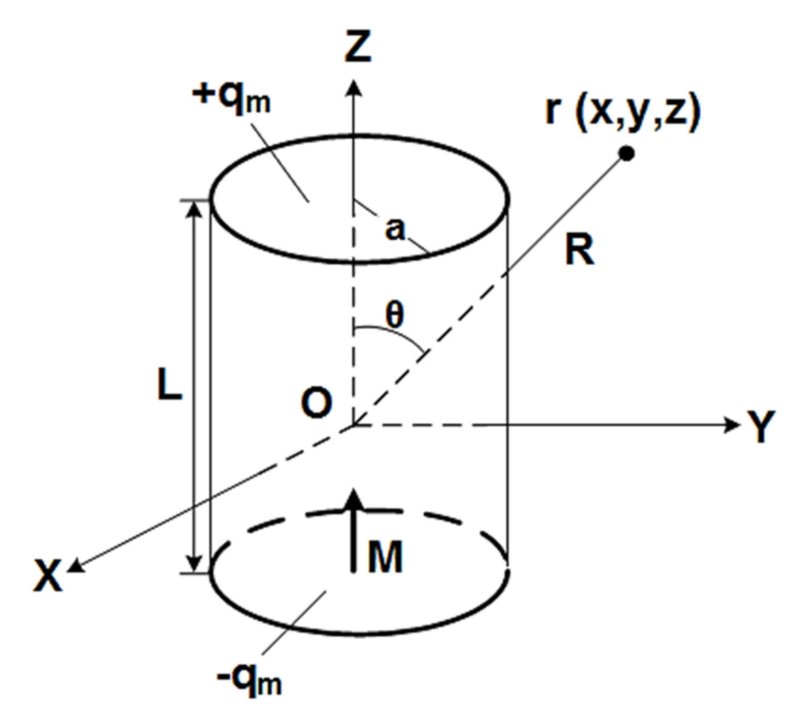
Therefore, the magnetic flux density of a uniformly magnetized ferrite antenna is determined as follows: A model of the ferrite antenna is shown in Figure 2, where L is the length of the antenna, a is the radius and M = azMo is the uniform magnetization along z-axis [22].
Using the concept of equivalent magnetic charge density to determine the magnetic flux density of the ferrite antenna, the magnetic flux density of the ferrite antenna obtains the same value as Equation (4) [22]. Converting the magnetic flux density expressed in the spherical coordinate system of Equation (4) into the Cartesian coordinate system gives:
Substituting Equation (5) into Equation (4), the magnetic flux density is given by:
where μr is the relative permeability of the ferrite antenna and MT = πa2LM0 is the total dipole moment of the ferrite antenna.
Here, the ferrite antenna mounted in the EV WPT system only considers the az component. Therefore, Equation (6) can be summarized as:
2.3. Open-Circuit Voltage
By Faraday’s law, the voltage induced in an electrically small loop antenna is equal to the rate of change of the magnetic flux. In addition, when the loop antenna is composed of multiple turns, the induced voltage of each turn is in series with all other turns [23]. Therefore, the open-circuit voltage is given by:
where Voc is the open-circuit voltage, N is the number of turns, Φ is magnetic flux.
If the loop is small compared with a wavelength, magnetic flux may be assumed to be constant throughout the loop area at any instant of time. The relationship between magnetic flux and magnetic flux density is given by [23]:
where A is the loop area, B is magnetic flux density and θ is the angle between the plane of the loop axis and the incoming flux.
An electromagnetic radiation field contains electric and magnetic field component. The field is given by [22]:
where E is the electric field and c is the speed of light.
Solving Equation (10) for magnetic flux density and substituting it into Equation (9) allows us to express the open-circuit voltage induced in a loop as a function of the electric field strength of the incoming electromagnetic signal [23].
The electric and magnetic field strength varies with time in a sinusoidal form. This study considers the peak magnitude of Voc. Therefore, dE/dt is simply E2πf. Equation (11) can be summarized as:
where ω is the angular frequency of θ. When the loop plane is 90° to the magnetic field, cosθ is 0 and Voc is zero.
The basic theory of the ferrite antenna is based on an electrically small loop antenna [24,25]. The ferrite antenna uses a ferrite rod in the loop to increase the radiation resistance, which results in better antenna efficiency, without increasing the physical size compared to a loop antenna with an air core.
From Equation (12), the open-circuit voltage of the ferrite antenna is given by:
where μeff is the effective permeability of the ferrite antenna and is the z-component of the incident magnetic flux density of the ferrite antenna.
The permeability of the ferrite antenna is characterized by a combination of ferrite material permeability, the shape of the ferrite antenna and the dimensions of the ferrite antenna [26]. The relative permeability of the ferrite antenna is given by:
where μr is the relative permeability of the ferrite antenna, μeff is the effective permeability of the ferrite antenna, lr is the length of the ferrite antenna and lc is the length of the ferrite antenna’s coil.
The open-circuit voltage of a single-turn loop in the middle of the ferrite antenna is increased by the factor μr for the value of the same loop in free space.
3. Analysis and Modeling to Use Ferrite Antenna
3.1. Analysis of Ferrite Antenna Used in the Automotive
As mentioned in SAE J2954, the ferrite antenna used for the precise positioning of the WPT system for EV should not electromagnetically interfere with EV during precise positioning and should not affect the charging efficiency during the WPT. In addition, for the precise positioning of the EV WPT system, the ferrite antenna transmitter should transmit a strong magnetic field within a range that satisfies the ITU regulation suitable for automotive [19] and the ferrite antenna receiver should accurately detect the magnetic field received by the ferrite antenna transmitter. Therefore, it was examined that the ferrite antenna, which was verified and used in an automotive, was suitable for the precise positioning of the WPT for an EV.
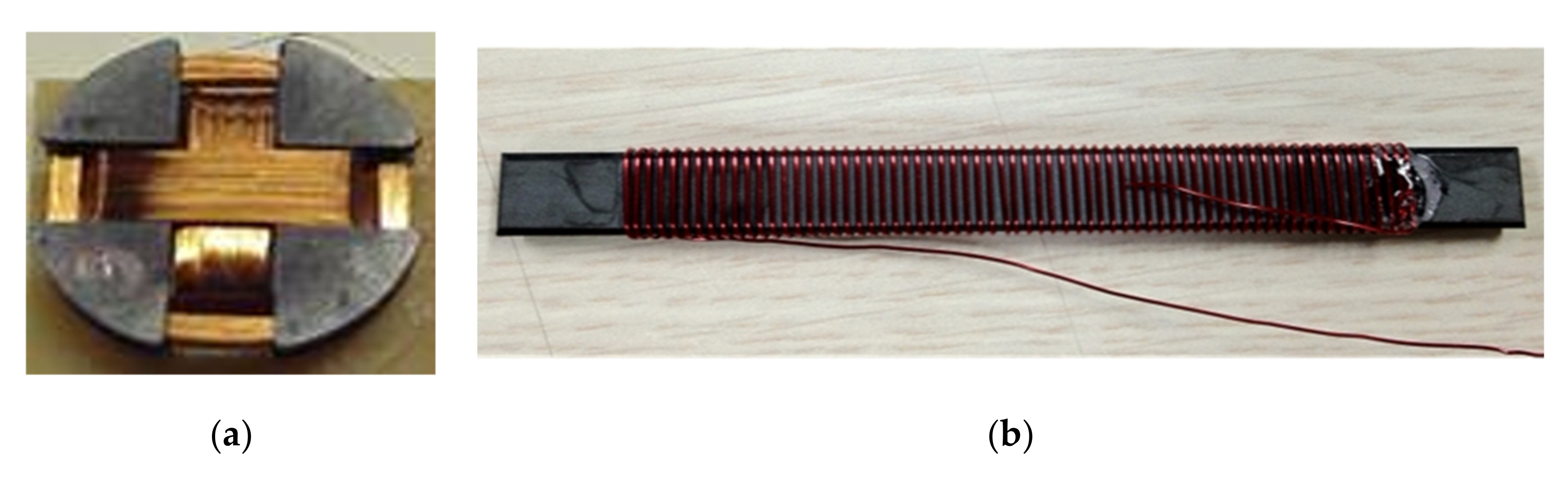
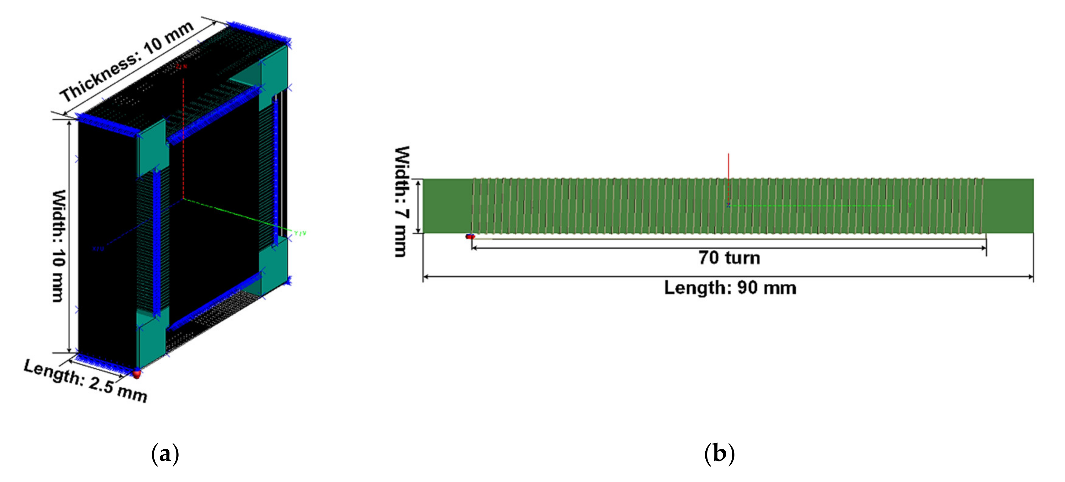
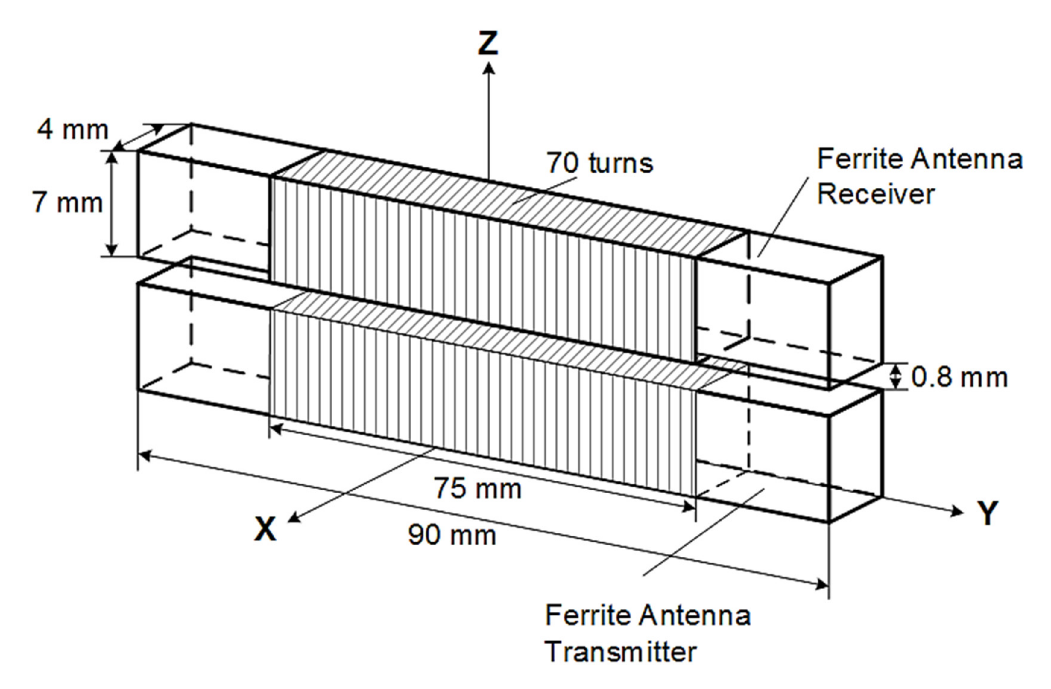
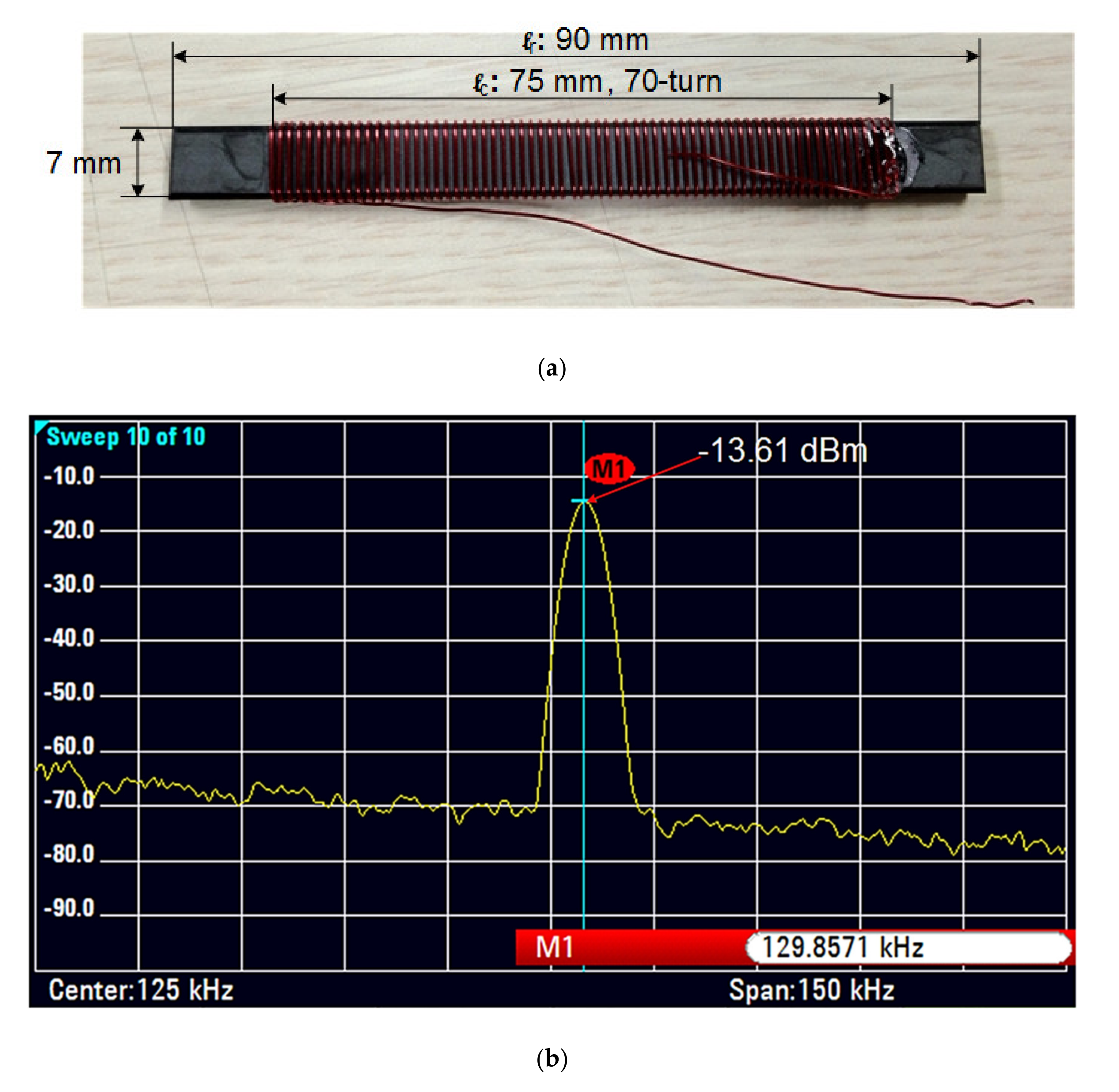
Figure 3 shows a ferrite antenna that was applied and used in the automotive. In the automotive, the ferrite antenna is used in two systems. One is a keyless entry system (see Figure 3a) and the other is a smart key system (see Figure 3b). The ferrite antenna used in the keyless entry system had a length of 2.5 mm, a width of 10 mm and a thickness of 10 mm. Two hundred turns of copper wire were wound around the width and thickness, and 91 turns were wound around the length. The ferrite antenna used in the smart key system had a length of 90 mm, a width of 7 mm, a thickness of 4 mm and 70 turns of copper wire. Both of the ferrite antennas demonstrated a relative magnetic permeability of 150, an operating frequency of 125 kHz, and did not electromagnetically interference with the EV. Therefore, to confirm that the ferrite antennas shown in Figure 3 are suitable for the precise positioning of the WPT system for EV, the magnetic flux density in the near-field was verified. We used FEKO from the Altair software package [27], simulation software widely used in industry and academia.
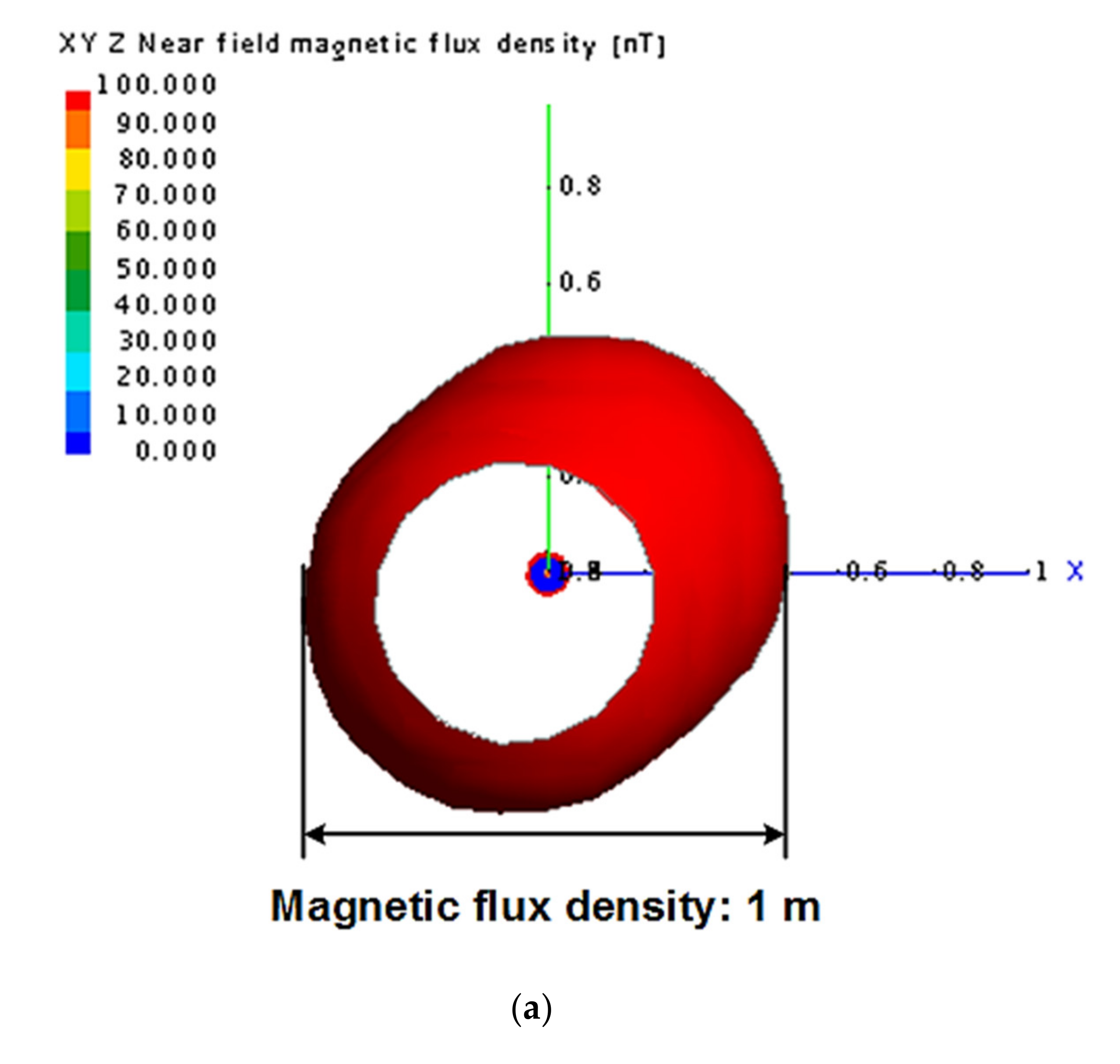
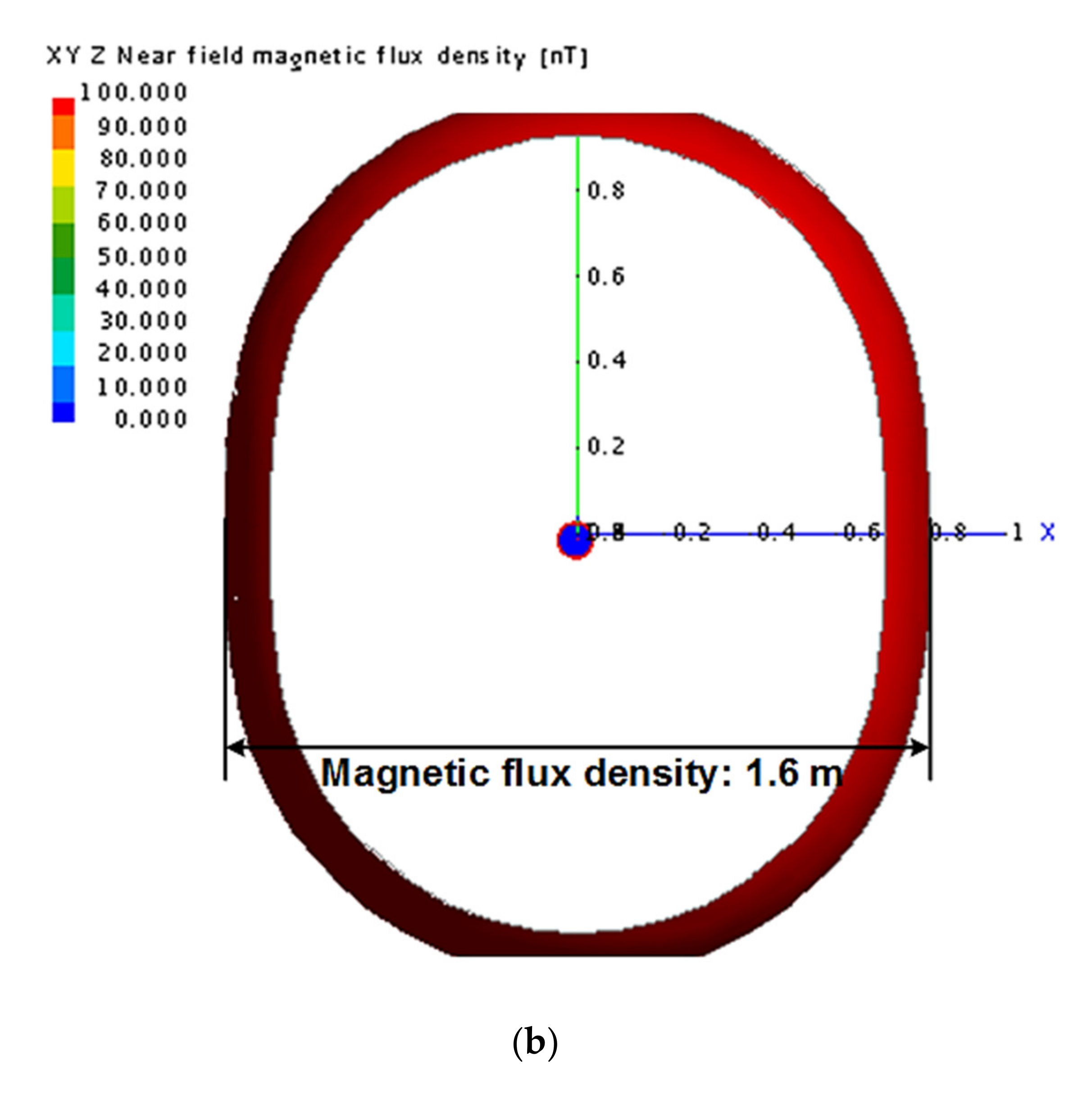
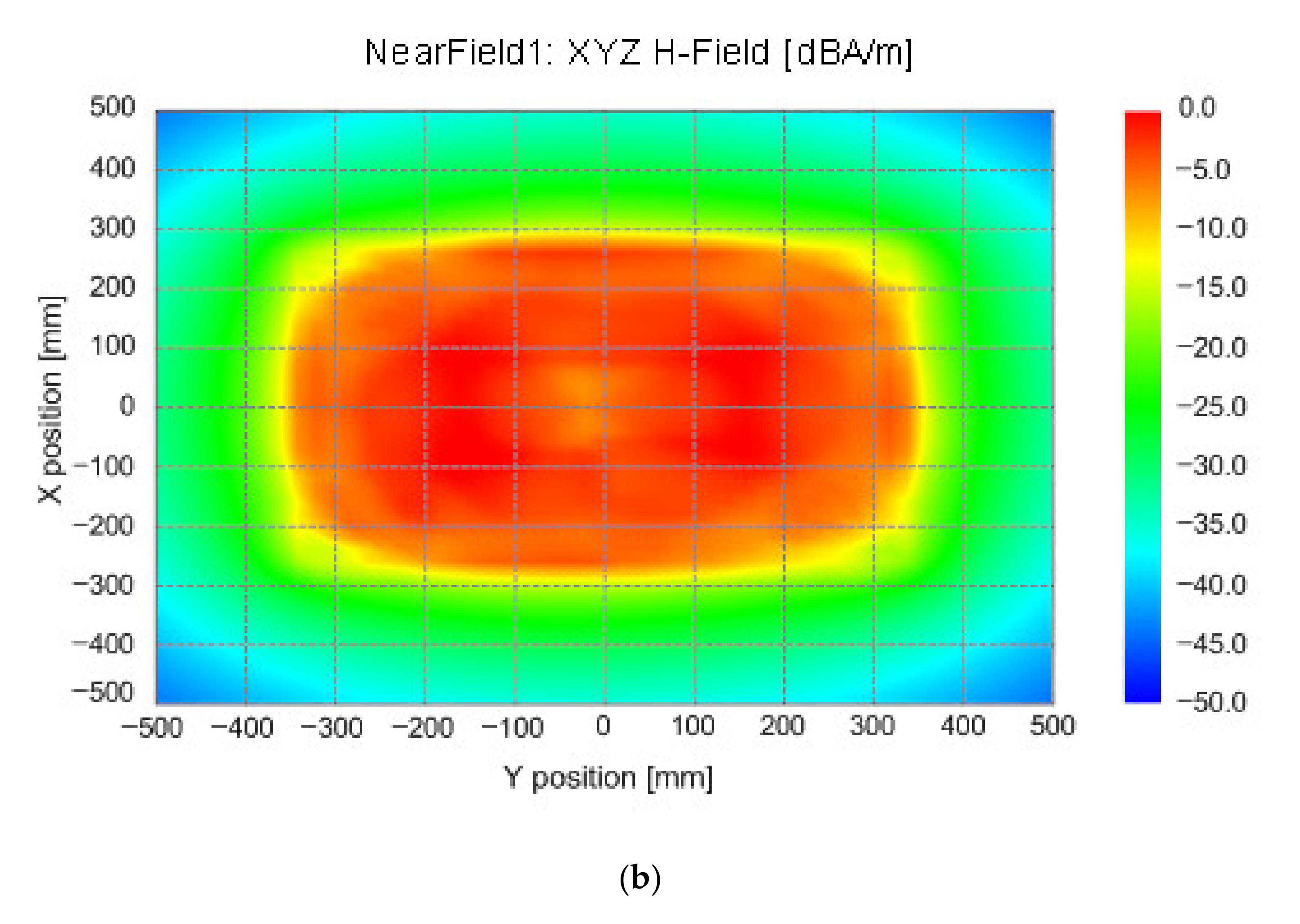
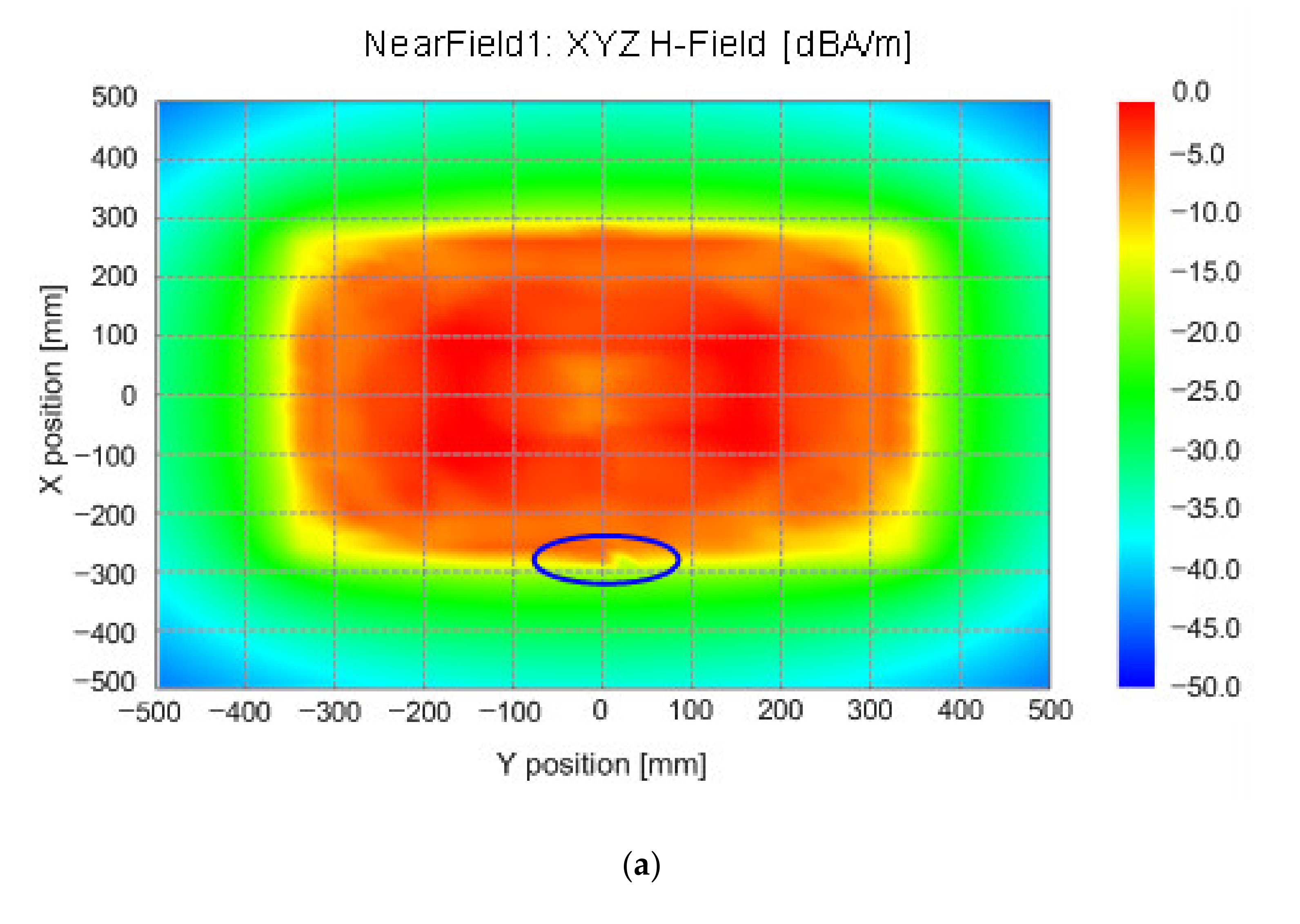
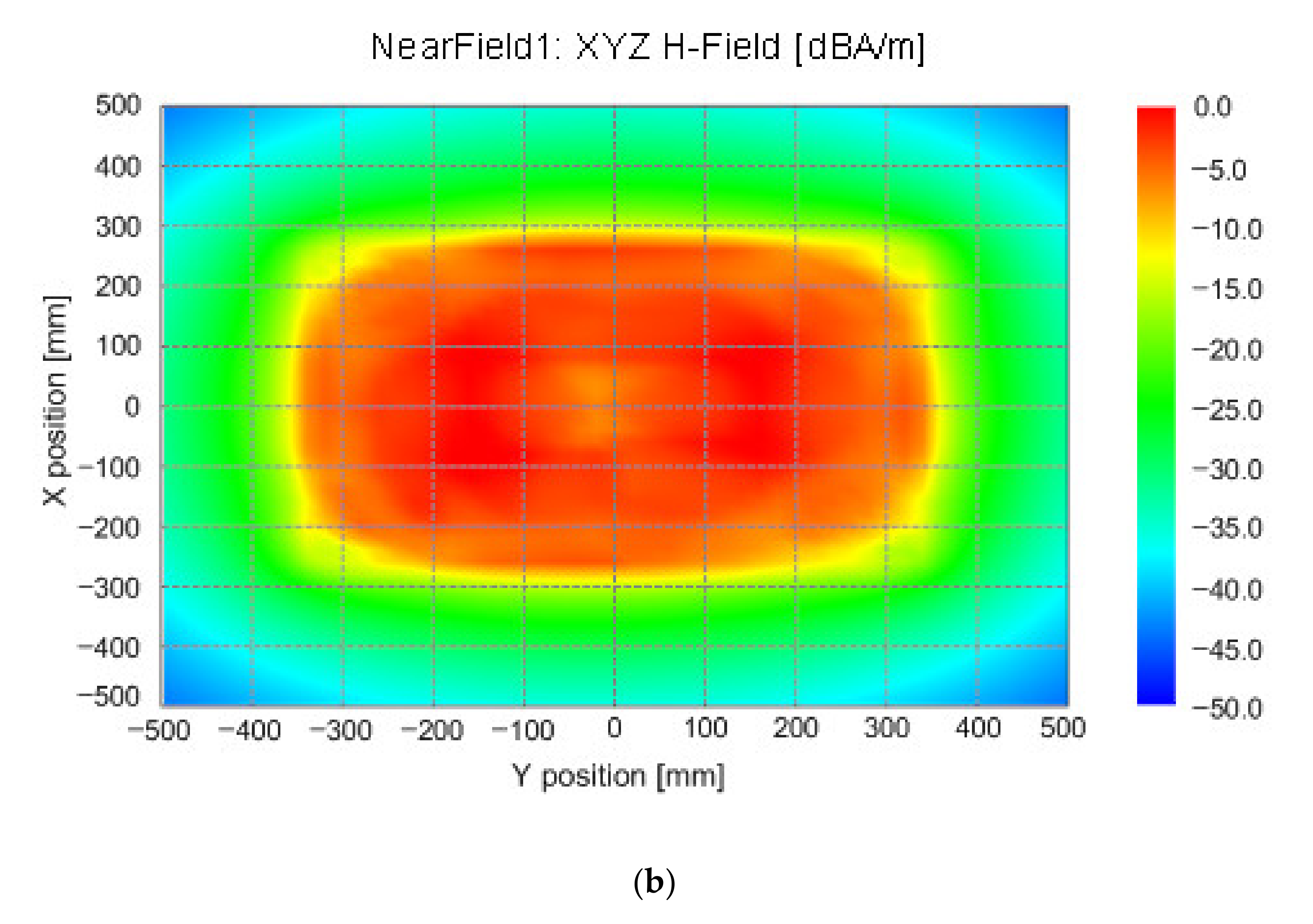
Figure 4 shows the design for simulation with FEKO software. All of the constants applied in the simulation were applied with all of the above-mentioned values. The result of the simulation of the ferrite antenna is shown in Figure 5. The ferrite antenna used in the keyless entry system has a magnetic flux density distance of 1 m and the ferrite antenna used in the smart key system has a magnetic flux density distance of 1.6 m. Precise positioning in the WPT system for EV requires that the secondary device mounted on the EV locates and aligns the primary device because the primary device is installed to the parking spot. Therefore, the ferrite antenna used in the smart key system is more suitable for precise positioning of the EV WPT systems than the ferrite antenna used in the keyless entry systems.
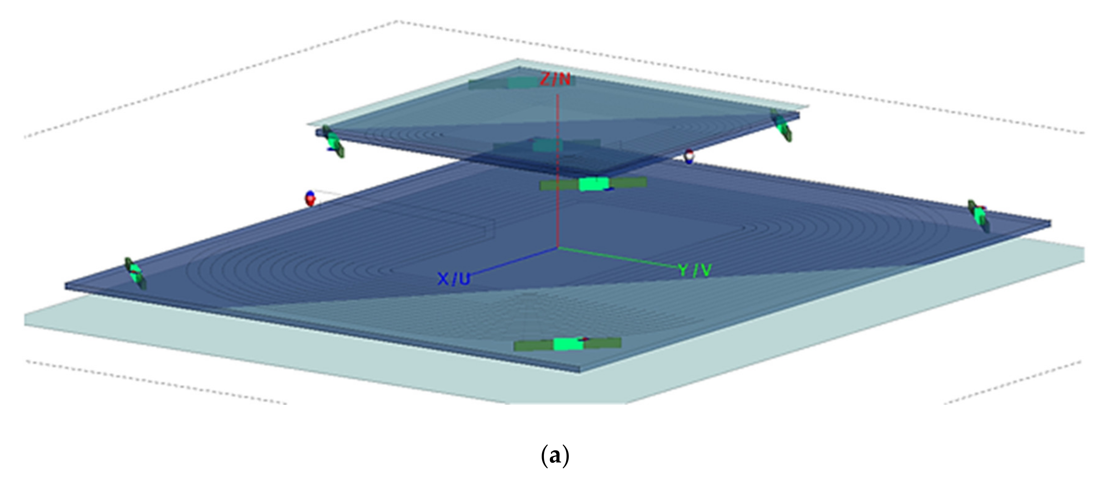
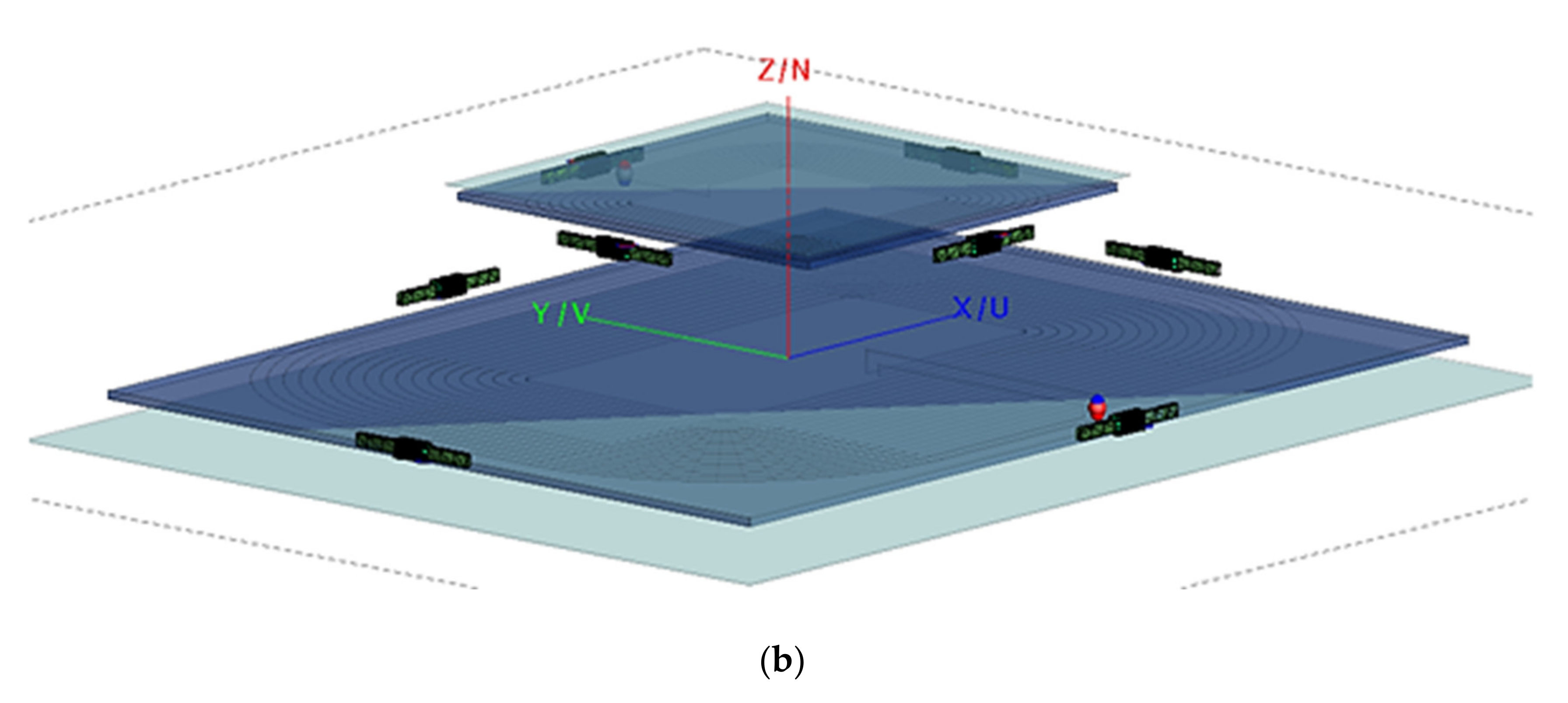
The ferrite antenna shown in Figure 6 was simulated using FEKO software to verify that the charging efficiency of the WPT system for EV was affected. The geometric dimensions of the WPT system for EV were based on the WPT1 power class of SAE J2954 [20]. Where the ferrite antenna can be mounted in the WPT system for EV is the corner of the primary and secondary devices or the center of each side. Figure 6 shows the ferrite antenna arranged on the WPT system for EV.
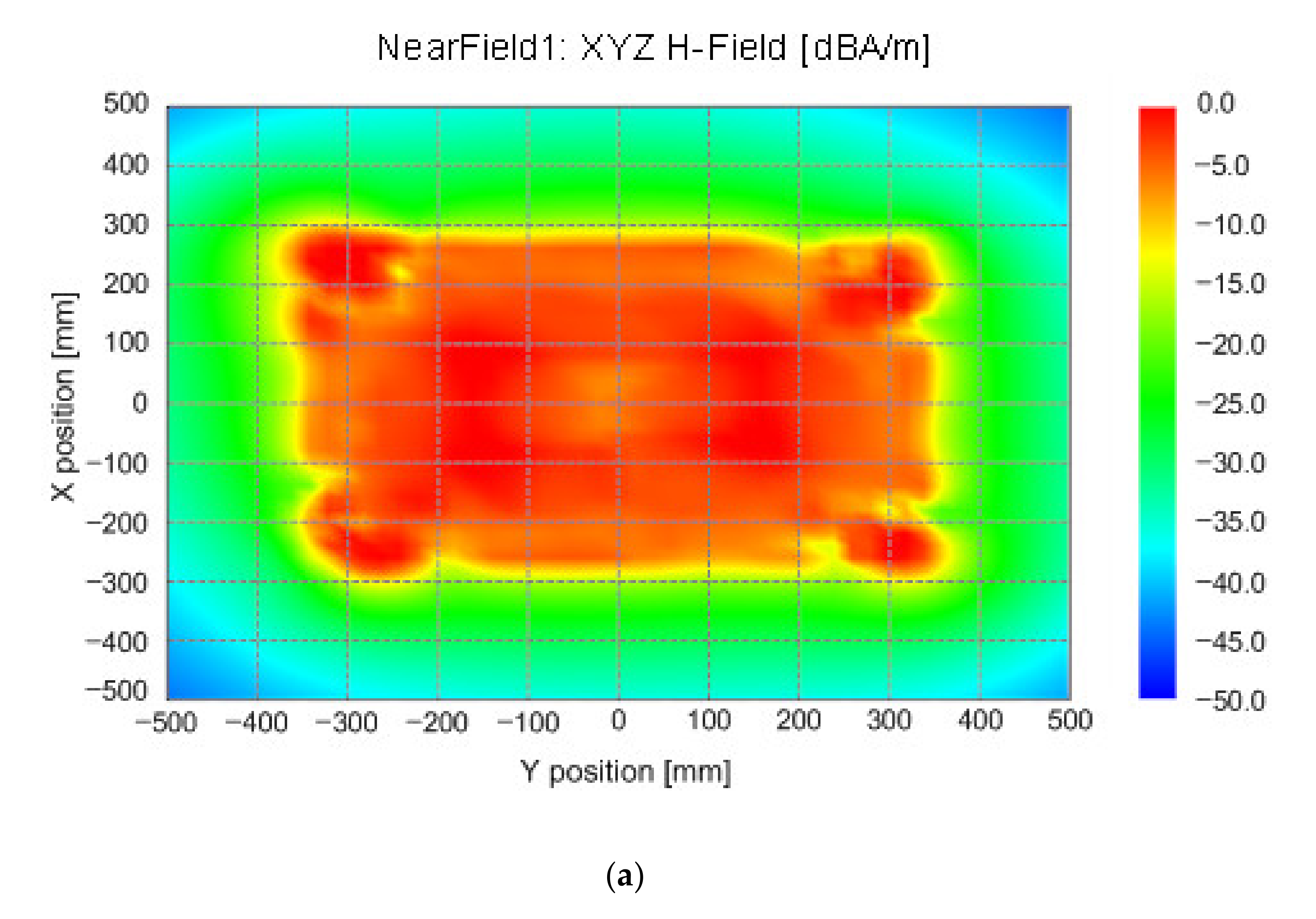
Figure 7 shows the simulation results when the ferrite antenna used in the keyless entry system and smart key system are mounted on each corner of the WPT system for EV. In the ferrite antenna used in the keyless entry system, the coils wound in three directions can be observed to affect the WPT system of EV (see Figure 7a). It was confirmed that the ferrite antenna with the coil wound on the ferrite rod in one direction did not affect the EV WPT system (see Figure 7b).
Figure 8 shows the simulation results when the ferrite antenna used in the keyless entry system and smart key system are mounted on the center of each side of the WPT system for EV. In the ferrite antenna applied in the keyless entry systems, the coils wound in three directions can be observed to affect the WPT system for EV (see Figure 8a). It was confirmed that the ferrite antenna with the coil wound on the ferrite rod in one direction did not affect the WPT system for EVs (see Figure 8b).
Based on the results shown in Figure 7 and Figure 8, the ferrite antenna, which affects the charging efficiency when the WPT system for the EV is wireless charging, is a coil wound to the ferrite rod in three directions. The magnetic vector when the primary device supplies power to the secondary device that of the ferrite antenna wound in one direction on the ferrite rod is in the same direction. Hence, the ferrite antenna wound in one direction on the ferrite rod does not affect the wireless charging efficiency. However, the magnetic vector when the primary device supplies power to the secondary device and that of the ferrite antenna wound in three directions on the ferrite rod is in a different direction. Hence, the ferrite antenna wound in three directions on the ferrite rod is observed to affect the wireless charging efficiency.
3.2. Ferrite Antenna Modeling for Application to the Precise Positioning of the EV WPT System
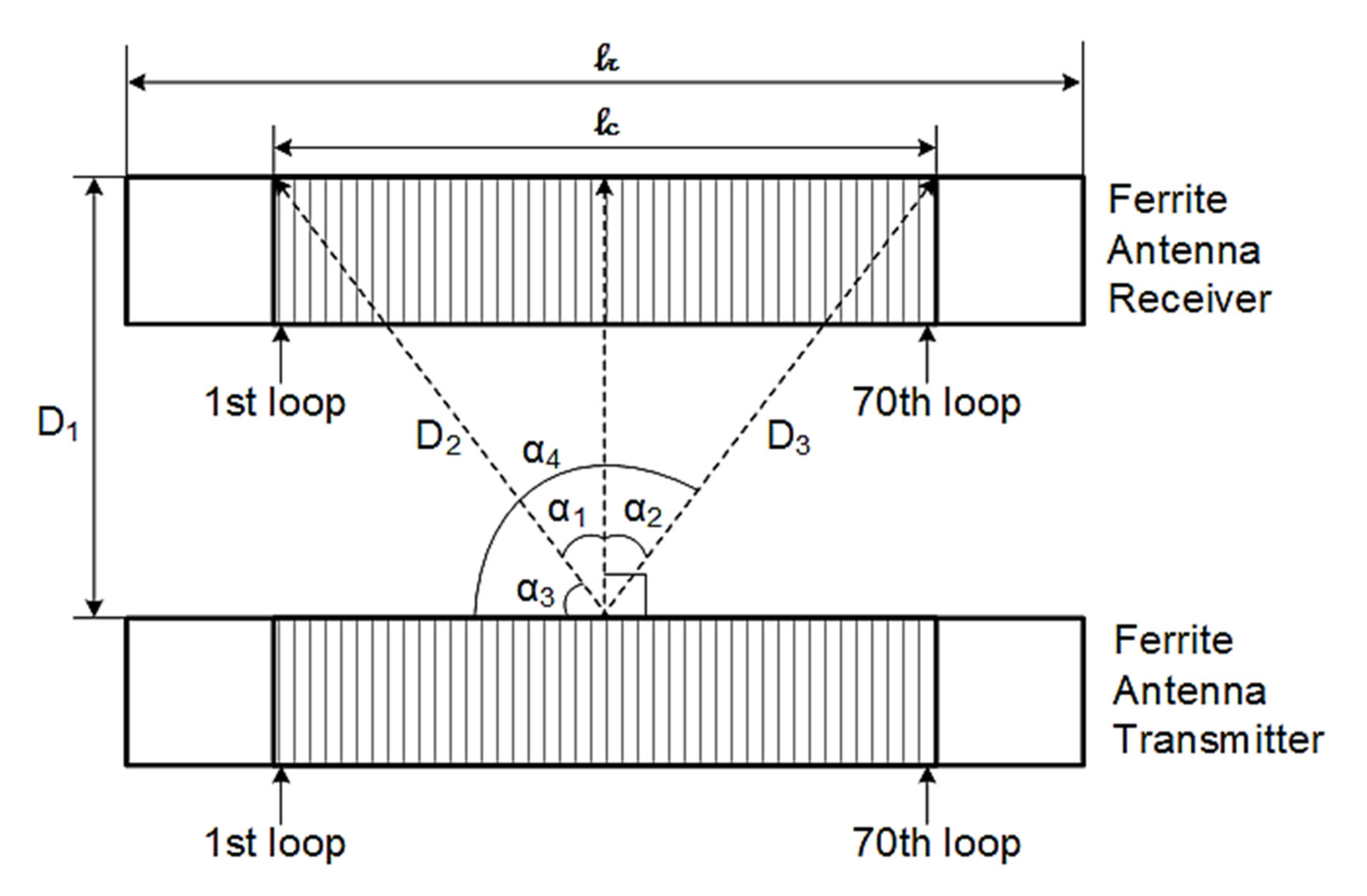
In order to use the ferrite antenna for the precise positioning of the WPT system for EV, it is necessary to verify whether it is suitable as a transmitter and receiver even at a short distance. The reason is that the ferrite antenna, generally used to a vehicle, operates as a transmitter and receiver at a distance of 1 m or more. Equations (7) and (13) are the result of one ferrite antenna. In the WPT system for EV, the ferrite antenna serves as both a transmitter and a receiver and consists of a pair. Therefore, we constructed modeling for simulation and conducted unit-level tests. Figure 9 shows the geometric dimensions of the ferrite antenna used for verification and the relationship between the transmitter and receiver of the ferrite antenna. Figure 10 is an yz-plane view for calculating the magnetic flux density and open-circuit voltage of the ferrite antenna.
In Figure 10, α1 is the angle between the Nth loop of the ferrite antenna transmitter and the 1st loop of the ferrite antenna receiver, α2 is the angle between the Nth loop of the ferrite antenna transmitter and the 2nd to 70th loops of the ferrite antenna receiver, α3 is the 90 degrees minus α1, α4 is the sum of α1, α2 and α3, D1 is the vertical distance between the transmitter and receiver of the ferrite antenna, D2 is the distance between the Nth loop of the ferrite antenna transmitter and the 1st loop of the ferrite antenna receiver, D3 is the distance between the Nth loop of the ferrite antenna transmitter and the 2nd to 70th loops of the ferrite antenna receiver, lc is the length of the ferrite antenna’s coil and lr is the length of the ferrite antenna.
As mentioned previously, when the loop antenna consists of multiple turns, the induced voltage of each turn is in series with all other turns [22]. Therefore, the open-circuit voltage of a ferrite antenna with 70 turns is the sum of all the open-circuit voltages all the 70 turns. If the magnetic flux density of the ferrite antenna shown in Figure 10 is expressed in the form of Equation (7), it is given by:
where Btot is the sum of the magnetic flux density transmitted by the 70-turn loop of the ferrite antenna transmitter to the 70-turn loop of the receiver. The magnetic dipole moment of the ferrite antenna (m) is 4.76 × 10⁻¹³ A·m2, the relative permeability of the ferrite antenna (μr) is 150, the operating frequency of the ferrite antenna is 125 kHz.
In addition, the open-circuit voltage that the ferrite antenna receiver receives from the transmitter is given by:
where Voctot is the sum of the open-circuit voltage that the ferrite antenna receiver receives from the transmitter.
As the value measured in the measurement instrument is expressed in dBm, Equation (16) can be written as:
where R is the resistance of the ferrite antenna and the value of resistance is 1.
A Ferrite antenna model results were calculated using MATLAB software from MathWorks [28]. A ROHDE and SCHWARZ SMC100A signal generator [29] was used as the instrument for generating a magnetic flux density in the ferrite antenna of the transmitter. The instrument for measuring the magnetic flux density of the ferrite antenna of the receiver was an RTE 1104 oscilloscope [30] from ROHDE and SCHWARZ. The characteristic impedance of the port connected to the signal generator to perform the test is 50 ohms. Figure 11 shows the ferrite antenna used for the unit-level measurement and the measurement results. The ferrite antenna (see Figure 11a) used for unit-level measurement has the same geometric dimensions and constants used for modeling. The measurement results when x-direction is 0 mm, y-direction is 0 mm and z-direction is 8 mm are shown in Figure 11b. When the ferrite antenna for the transmitter and the ferrite antenna for the receiver are placed in parallel in the z-direction, the measured value of the induced open-circuit voltage received by the ferrite antenna for the receiver is −13.61 dBm.
Table 2 shows the comparison between the simulation and experimental results calculated by applying Equation (17) at the boundary of the alignment tolerance range of x-, y- and z-direction. It can be seen that the simulation and the unit-level experimental results are similar even when the transmitter and receiver of the ferrite antenna are matched, in addition to each alignment tolerance range boundary line.
4. Simulation and Analysis for Component-Level of EV WPT System
In this section, we discuss extending the magnetic flux density and open-circuit voltage models of the ferrite antenna to the EV WPT system.
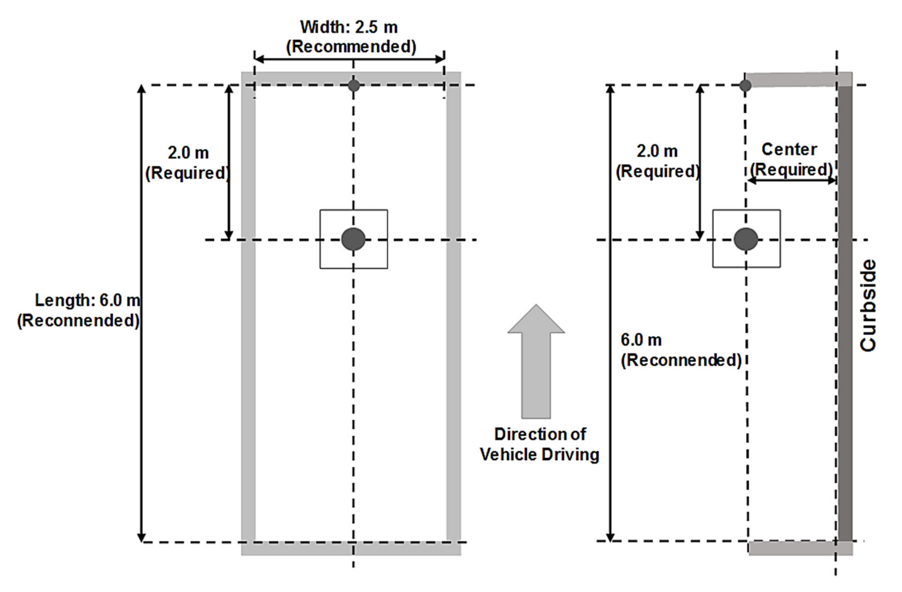
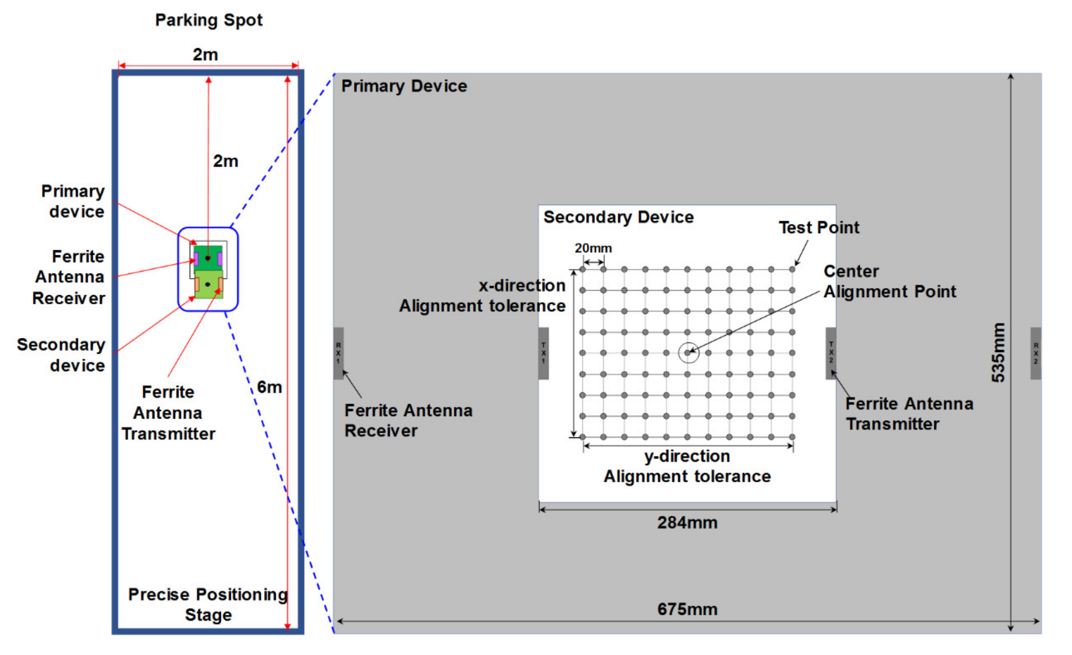
In the SAE J2954, when an EV mounted with WPT system parks in a parking spot for charging, front parking is recommended [20]. The geometric center of the primary device shall be installed at the center of the width of the parking spot and 2 m from the inner of the line in front of the parking spot, as shown in Figure 12. Therefore, considering the location of the primary device installed at the parking point, the mounting of the ferrite antenna is optimal in the direction ±y of the primary device and the secondary device. In addition, the minimum number of ferrite antennas to be mounted on the primary device and the secondary device is two for accurate direction recognition [31].
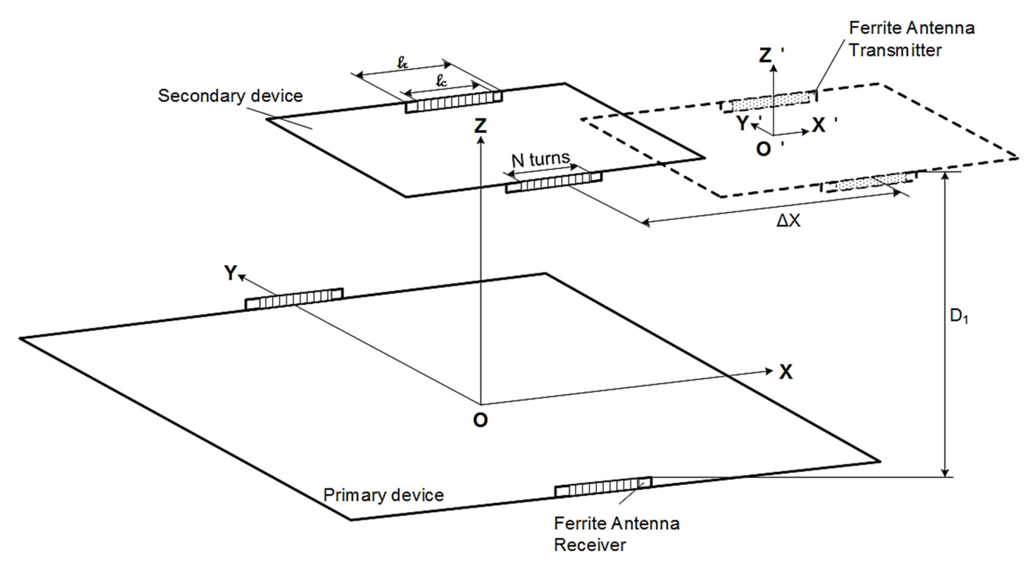
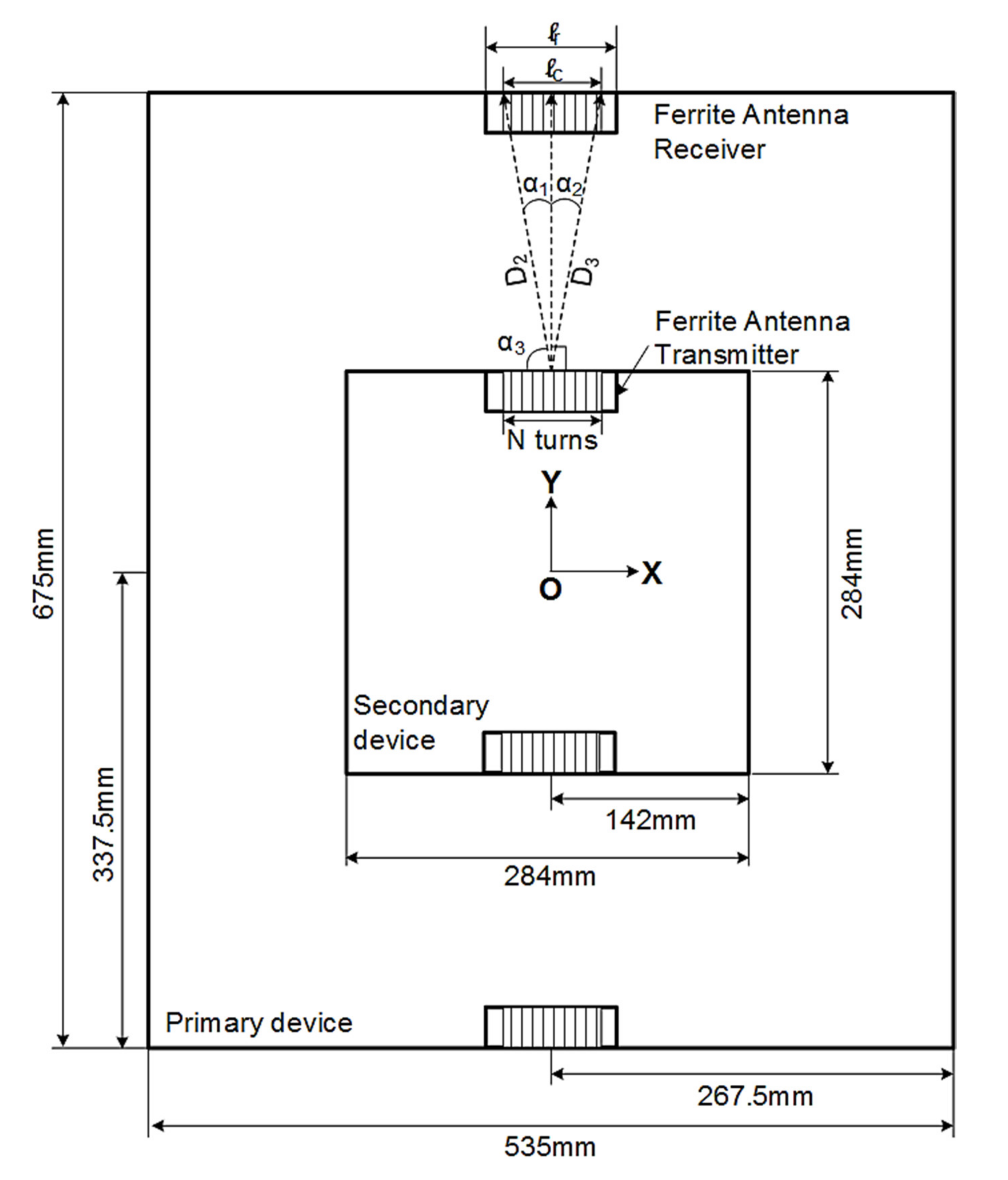
Figure 13 shows the secondary device to find the center alignment point of the primary device within the alignment tolerance area of the EV WPT system when the ferrite antenna arrangement is optimized for the primary device and the secondary device. Figure 14 shows the geometric dimensions and the xy-plane view for applying the simulation model.
In Figure 14, α1 is the angle between the Nth loop of the ferrite antenna transmitter in the ±y-direction mounted on the secondary device and the 1st loop of the ferrite antenna receiver in the ±y-direction mounted on the primary device, α2 is the angle between the Nth loop of the ferrite antenna transmitter in the ±y-direction mounted on the secondary device and the 2nd to 70th loops of the ferrite antenna receiver in the ±y-direction mounted on the primary device, D2 is the angle between the Nth loop of the ferrite antenna transmitter in the ±y-direction mounted on the secondary device and the 1st loop of the ferrite antenna receiver in the ±y-direction mounted on the primary device, D3 is the angle between the Nth loop of the ferrite antenna transmitter in the ±y-direction mounted on the secondary device and the 2nd to 70th loops of the ferrite antenna receiver in the ±y-direction mounted on the primary device, and D1 is the vertical distance between the transmitter and receiver of the ferrite antenna. The application of the geometric dimensions of Figure 14 to Equations (15) and (16) are detailed in Appendix A.
In order to find the center alignment point of the primary device within the alignment tolerance area, the secondary device should check the WPT efficiency at a point 20 mm from the ±x- and ±y-direction. Figure 15 shows 99 test points to find the center alignment point of the primary device within the alignment tolerance area. In Figure 15, the gray area is the primary device. The size of the primary device is 675 mm × 535 mm. The white area is the secondary device. The size of the secondary device is 284 mm × 284 mm. The distance between each test point is 20 mm.
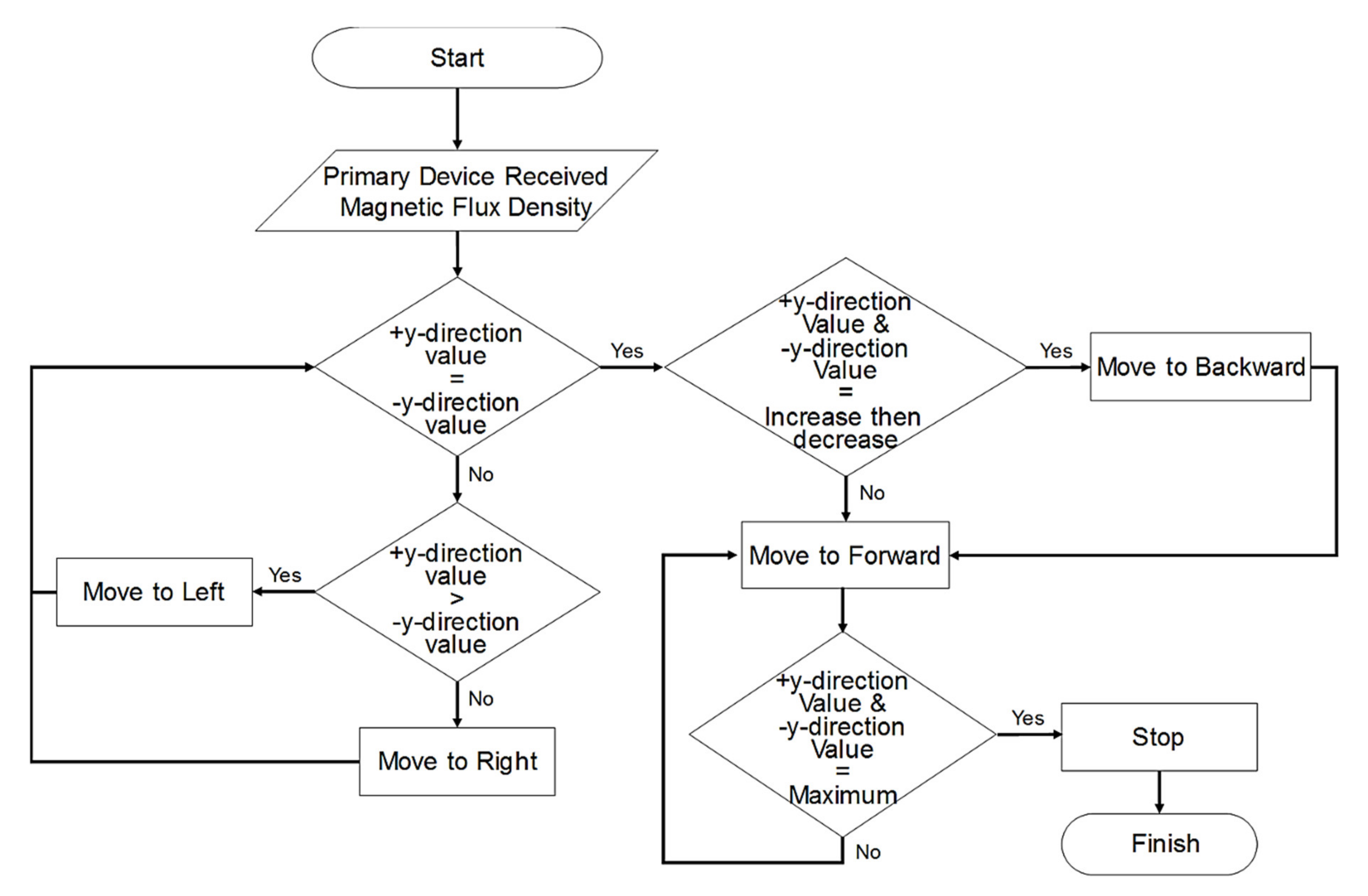
The sequence for finding the center alignment point of the primary device and secondary device using the ferrite antenna within the alignment tolerance area of the EV WPT system is proposed as follows: (i) The primary device’s ferrite antenna receiver is received magnetic flux density from the secondary device’s ferrite antenna transmitter; (ii) The primary device is compared to the received magnetic flux density in the +y- and −y-directions; (iii) If the magnetic flux density value in the +y-direction is greater than in the −y-direction, the secondary device is moved to the left. If the magnetic flux density value in the +y-direction is smaller than in the −y-direction, the secondary device is moved to the right. (iv) If the magnetic flux density value in the +y- and −y-direction was equaled, the secondary device is at the center of the width of the parking spot. (v) If the magnetic flux density value was equaled and has decreased after an increase, the secondary device is moved to the backward because it has already passed the center alignment point of the primary device. (vi) If the magnetic flux density value was equaled, but has not decreased after an increase, the secondary device is moved to the forward because the secondary device has not reached the center alignment point of the primary device. (vii) If the magnetic flux density value in the +y- and −y-direction is the maximum, the secondary device is stopped because it has reached the center alignment point of the primary device. The sequence for finding the center alignment point within the alignment tolerance area is shown in Figure 16.
Using MATLAB software, model results of 99 points were calculated by the secondary device to find the center alignment point of the primary device within the alignment tolerance area of the EV WPT system. As component-level and vehicle-level verification are required, the EV WPT system data are reflected as much as possible. We used an EV WPT system with an output power level of up to 7.7 kVA for the supply device and an input power level of up to 3.7 kVA for the EV device. The height of the primary device and the secondary device was 180 mm [32].
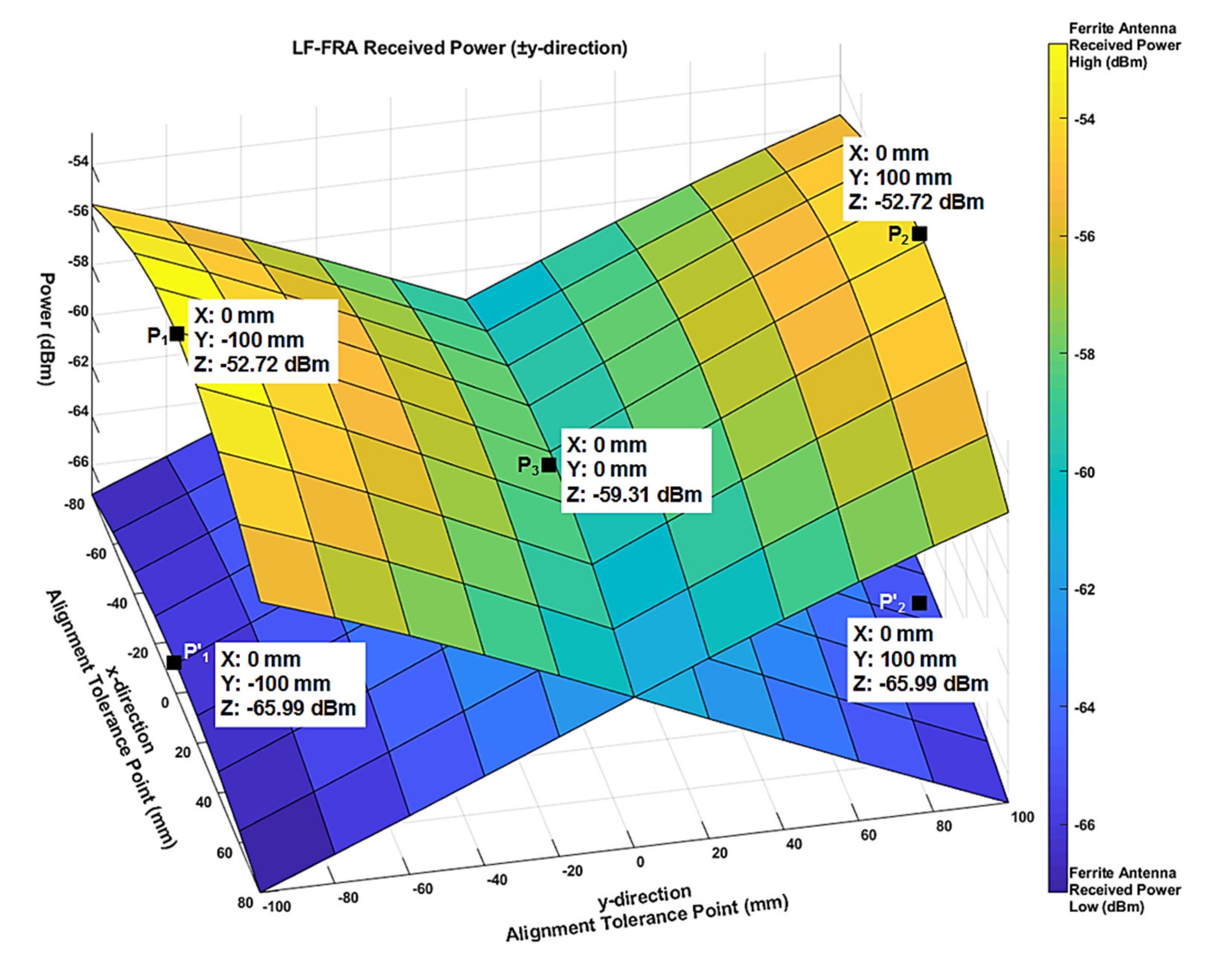
Figure 17 shows the results of simulation by applying Equation from (1) to (3) at 99 test points. In Figure 17, P1 and P’1 have a secondary device located at 0 mm in the x-direction and −100 mm in the y-direction, respectively, among the alignment tolerance areas of the primary device. Here, the ferrite antenna received power of the primary device is −52.72 dBm for ferrite antenna (Rx1) located at −y-direction and −65.99 dBm for ferrite antenna (Rx2) located at +y-direction. It shows that the secondary device is located to the left of the center alignment point of the primary device. Therefore, the secondary device is moved to the right. Similar results were observed for in P2 and P’2. As P2 and P’2 mean that the secondary device is located to the right, the secondary device is moved to the left. In P3, the secondary device is located in the alignment tolerance area of the primary device. Here, by comparing the ferrite antenna received power of the primary device, it can be seen that the values of Rx1 located in −y-direction and Rx2 located in +y-direction are the same as −59.31 dBm.
5. Experimental Results
In the EV WPT system, using the ferrite antenna mounted on the secondary device, an actual test was conducted to ensure that the secondary device could correctly locate the center alignment point of the primary device within the primary device’s alignment tolerance area. In the actual test, the WPT system used a primary device with a maximum input power of 7.7 kW and a secondary device with a maximum output power of 3.7 kW. Parameter of the primary and secondary devices are shown in Table 3.
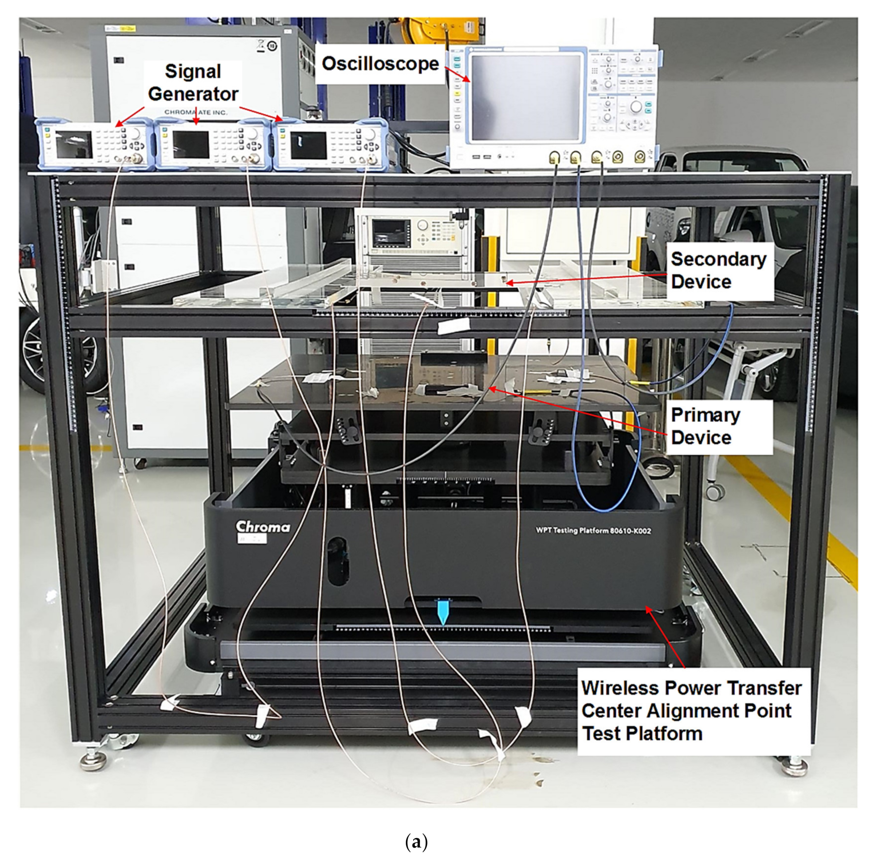
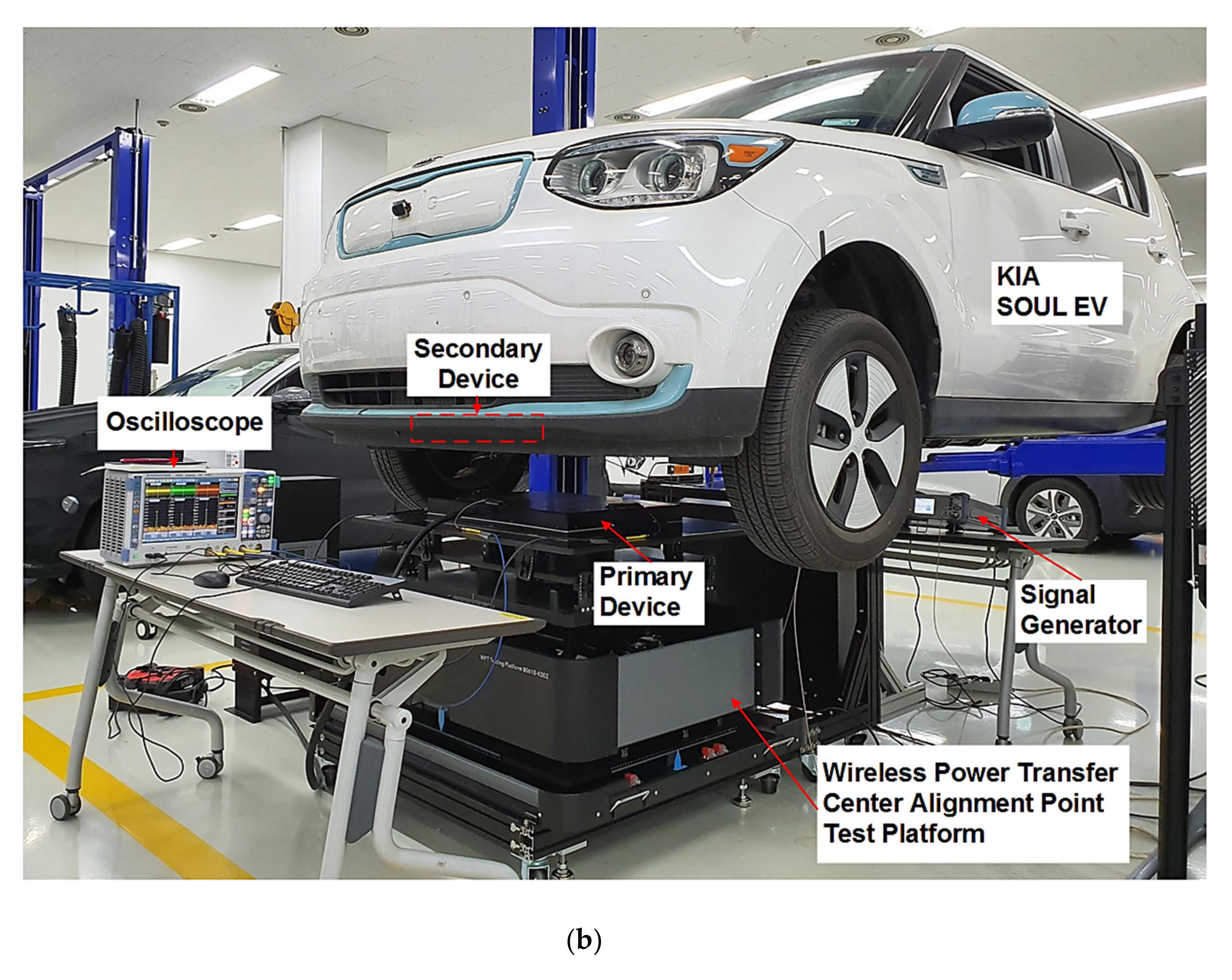
To verify the validity of the modeling and simulation results, a component-level and vehicle-level experimental benches were built. Figure 18a shows a component-level experimental bench to find the center alignment point within the alignment tolerance area of the EV WPT system. Figure 18b shows a vehicle-level test bench to find the center alignment point within the alignment tolerance area by installing the EV WPT system on a KIA SOUL EV. A ROHDE and SCHWARZ SMC100A signal generator was used to generate magnetic flux density in the ferrite antenna transmitter of the secondary device. The characteristic impedance of the connected to the signal generator to perform the test is 50 ohms. A ROHDE and SCHWARZ RTE 1104 oscilloscope was used to measure the open-circuit voltage in the ferrite antenna receiver of the primary device. The WPT Testing Platform from Chroma [33] is a device that can move 1 mm steps for ±x-, ±y and ±z-direction. As it is difficult to move the vehicle by 20 mm in a vehicle-level test, the primary device was moved by 20 mm to conduct the test. In order to match the experimental conditions of the component-level and vehicle-level, the primary device was tested by moving it by 20 mm. This was also performed at the component-level. The simulation and actual experimental results measured at 99 points were compared and analyzed for each point. In addition, in order to increase the reliability of the measured data, after measuring 99 points at both the component-level test and the vehicle-level test, the same test was repeated 10 times to check the difference in measured values for each number of times.
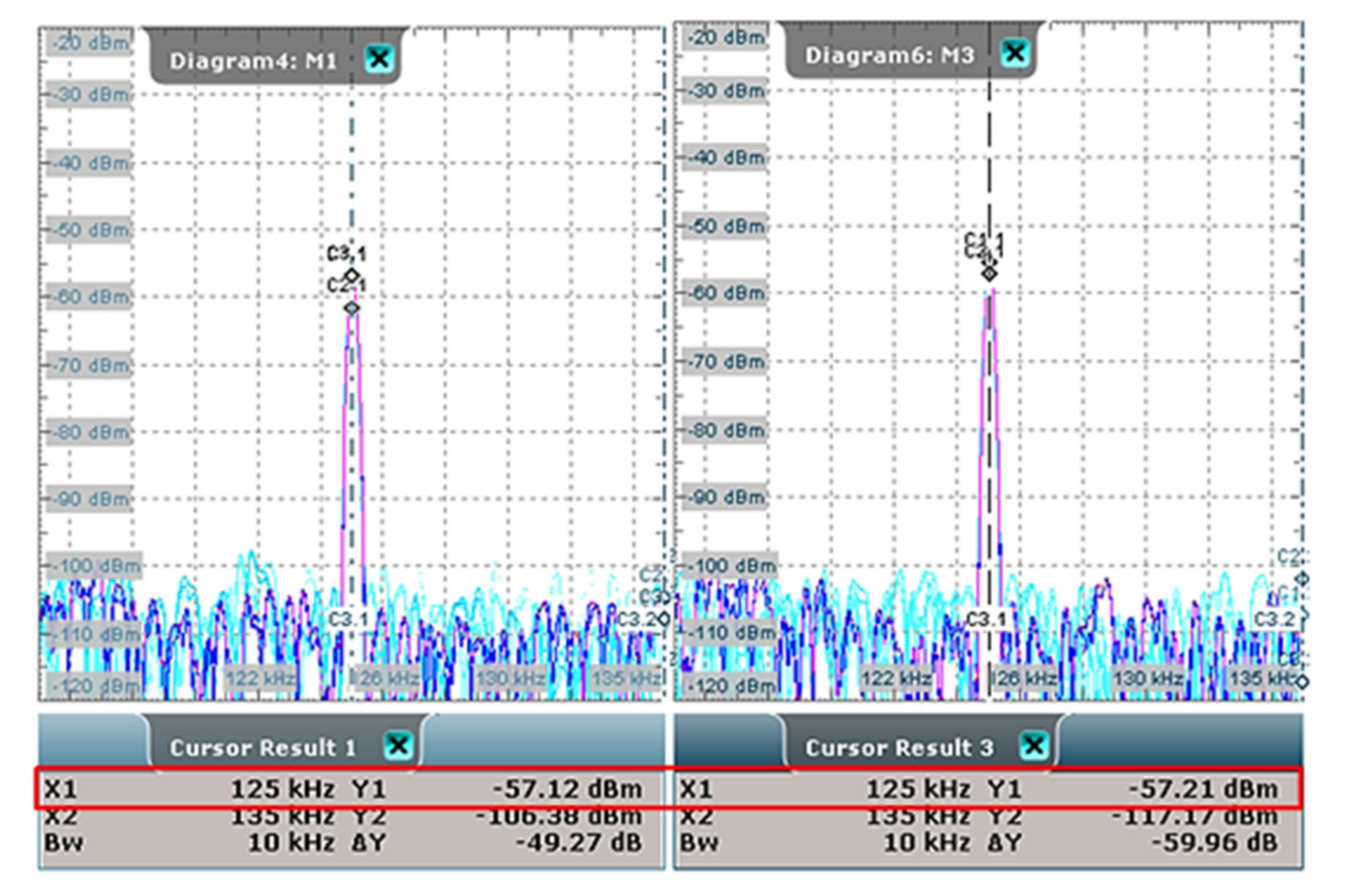
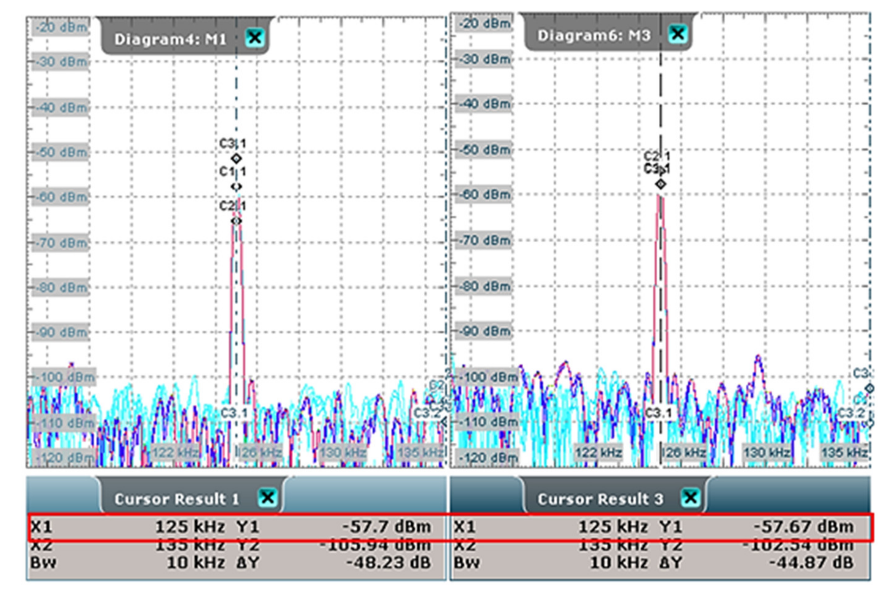
Figure 19 and Figure 20 shows the results of the oscilloscope measurement waveform when the secondary device is positioned at the center alignment point of the primary device. In each Figure, cursor result 1 is the result measured by the −y-direction of the ferrite antenna receiver of the primary device. In addition, cursor result 3 is the result measured by the +y-direction of the ferrite antenna receiver of the primary device.
As mentioned in Section 4, according to the simulation results, if the secondary device is located at the center alignment point of the primary device, the output of the ±y-direction ferrite antenna receiver mounted on the primary device should be the same. In Figure 19, the value of cursor results 1 is −57.12 dBm and that of cursor result 3 is −57.21 dBm. The measurement error guaranteed by the signal generator and oscilloscope is 2% and the difference between the value of cursor result 1 and the value of cursor result 2 is 0.09 dBm. Therefore, in the component-level test, it can be observed that the output of the ±y-direction ferrite antenna receiver mounted on the primary device is the same. Similarly, in the vehicle-level test (see Figure 20), the difference between the value of cursor result 1 and that of cursor result 3 is 0.03 dBm. Hence, it can be seen that the output of the ±y-direction ferrite antenna receiver mounted on the primary device is the same. Therefore, it can be confirmed that the secondary device is located at the center alignment point of the primary device in the component-level and the vehicle-level test.
Table 4 and Table 5 compare the results of simulation, component-level and vehicle-level tests at important points among the 99 test points. The reason for selecting the five important points mentioned in Table 4 and Table 5, is that the results at each endpoint of the primary device and its center alignment point are of paramount importance. Analysis of the results in Table 4 and Table 5 shows that the component-level and vehicle-level measurement results showed a difference of less than 1 dBm. This is the difference less than 2%, which is the measurement error guaranteed by the signal generator and oscilloscope, the measurement equipment. Hence, the measurement results of component-level and vehicle-level are the same. However, the difference between the simulation and the actual experimental result is less than 3 dBm at maximum. This is more than the measurement error guaranteed by the measurement equipment. Therefore, in order to reduce the difference between the simulation value and the actual experimental result, it is necessary to review the environmental conditions of the EV WPT system as well as the environmental conditions of the EV.
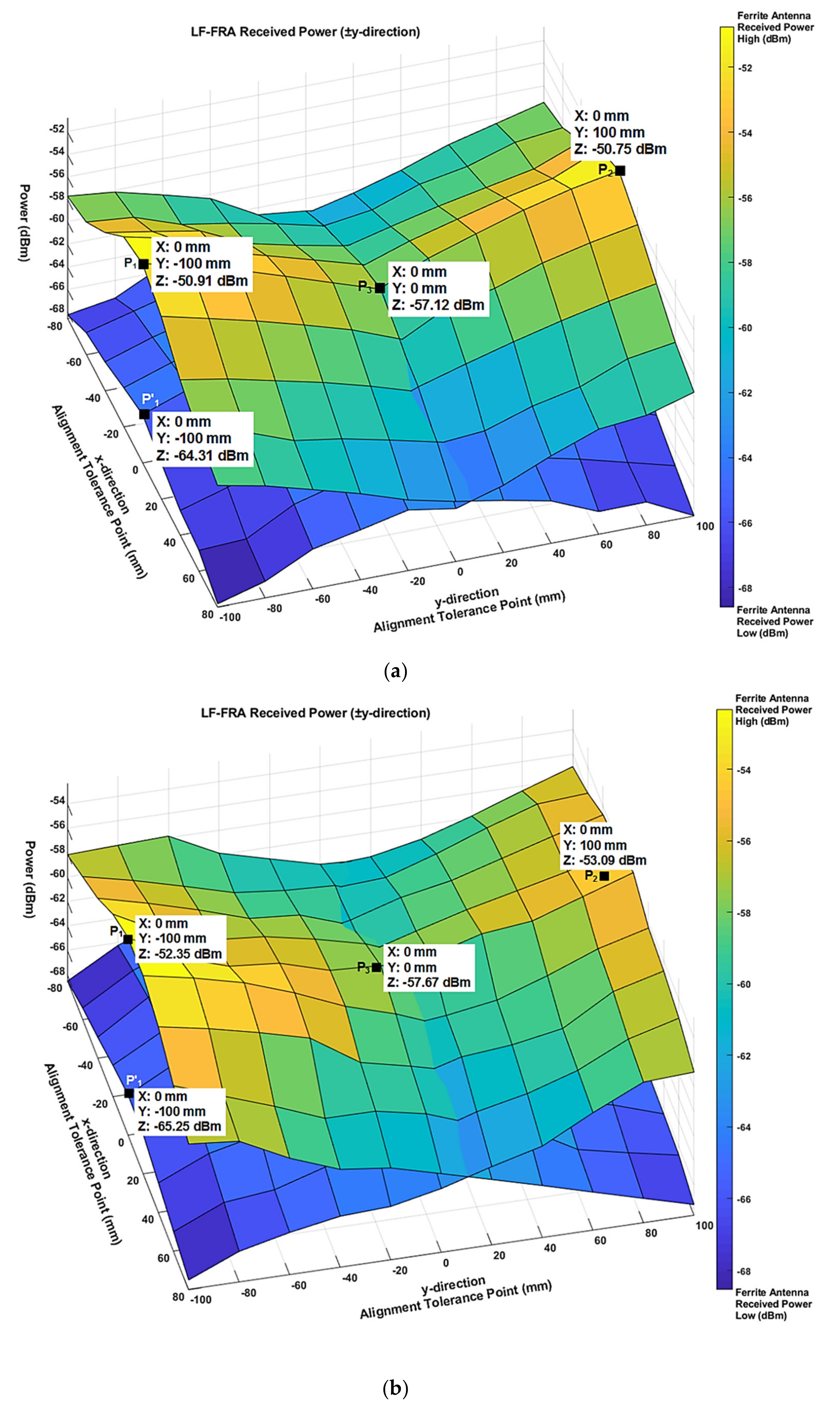
Figure 21 show the component-level and vehicle-level results for 99 points. Figure 21 shows that the results of the component-level and vehicle-level show the same tendency when the secondary device is positioned at 0 mm in the x-direction and −100 mm in the y-direction among the alignment tolerance areas of the primary device. In component-level (see Figure 21a), the ferrite antenna received power of the primary device is −50.91 dBm for ferrite antenna (Rx1) located at the −y-direction and −64.31 dBm for ferrite antenna (Rx2) located at the +y-direction. This indicates that the secondary device is on the left-side of the center alignment point of the primary device. Therefore, the secondary device is moved to the right. Similarly, in vehicle-level (see Figure 21b), the ferrite antenna received power of the primary device is −52.35 dBm for ferrite antenna (Rx1) located at the −y-direction and −65.25 dBm for ferrite antenna (Rx2) located at the +y-direction. This also indicates that the secondary device is on the right-side of the center alignment point of the primary device. Therefore, in vehicle-level testing, the secondary device is moved to the left. It can be confirmed that these results show the same tendencies as those of the simulation result, as shown in Figure 17.
6. Conclusions
In order to maximize the charging efficiency of the EV MF-WPT system, it is important to match the center alignment points of the primary and secondary devices. In this article, we proposed how to use the ferrite antennas to find a central alignment point between the primary and secondary units within the alignment tolerance area that requires the minimum power transfer efficiency of the EV WPT system. First, the ferrite antenna used for precise positioning of the EV WPT should not affect the charging efficiency when the primary device transmits power to the secondary device. Therefore, it was analyzed that the mounting position of the ferrite antenna should be mounted at the center of each side with ±y-direction of the primary device and the secondary device using electromagnetic simulation. Second, the method suggested that it is necessary to calculate all induced loop voltages in the relationship between incident magnetic field signal strength and induced loop voltage because of the distance between the transmitter and receiver of the ferrite antenna in EV WPT precise positioning is short to within 250 mm. After the simulation was performed on the suggestions, the unit-level test was performed to validate the simulation results. Since the difference between the simulation result and the experimental result was within one decibel-milliwatt, it could be confirmed that the proposed induced loop voltage formula was applied correctly. The reason is that the error guarantee range of the measurement equipment is two decibel-milliwatts. Third, even if two ferrite antennas are mounted on each of the primary device and the secondary device, a method that can match the central alignment points of the primary and the secondary devices were proposed, and a sequence was also proposed. The difference between the simulation results and the experimental results was within two decibel-milliwatts for component-level and within three decibel-milliwatts for vehicle-level. Consequently, we confirmed that the ferrite antenna is a suitable method to find the center alignment points of the primary and secondary devices within the alignment tolerance area of the EV WPT system.
In the future, it is necessary to review the environmental conditions of EV and EV WPT systems to reduce the error of less than one decibel-milliwatt between simulation results and vehicle-level experimental results. In addition, the EV driver must make considerable effort to directly align the vehicle to identify the central alignment point of the base unit. Therefore, it is necessary to review the research that combines the precise positioning of the autonomous driving parking system and the electric vehicle wireless transmission system.
7. Patents
Seong, J.Y. Method and apparatus for position alignment using low-frequency antennas in wireless power transfer system. EP.3364522.B1. US.10622846.B2. 2020, http://kpat.kipris.or.kr/kpat/biblioa.do?method=biblioFrame (accessed on 20 May 2020).
Author Contributions
Conceptualization, J.Y.S. and S.-S.L.; methodology, J.Y.S.; software, J.Y.S.; validation, J.Y.S.; investigation, J.Y.S.; data curation, J.Y.S.; writing—original draft preparation, J.Y.S.; writing—review and editing, J.Y.S. and S.-S.L.; visualization, J.Y.S.; supervision, S.-S.L. All authors have read and agreed to the published version of the manuscript.
Funding
This research was supported by the 2016–2017 R&D Technical Fund of Hyundai Motor Company.
Conflicts of Interest
The authors declare no conflicts of interest.
Appendix A
From Equation (15), the magnetic flux density applying the geometric dimensions of Figure 14 is given by:
where BWPTtot is the sum of the magnetic flux density transmitted by the 70-turn loop of the ferrite antenna transmitter mounted on the secondary device to the 70-turn loops of the ferrite antenna receiver mounted on the primary device, μ0 is the permeability of free space, μr is the relative permeability of the ferrite antenna, m is the magnetic dipole moment, α1 is the angle between the Nth loop of the ferrite antenna transmitter in the ±y-direction mounted on the secondary device and the 1st loop of the ferrite antenna receiver in the ±y-direction mounted on the primary device, α2 is the angle between the Nth loop of the ferrite antenna transmitter in the ±y-direction mounted on the secondary device and the 2nd to 70th loops of the ferrite antenna receiver in the ±y-direction mounted on the primary device, SDΔx is the distance the secondary device moves in the ±x-direction, SDΔy is the distance the secondary device moves in the ±y-direction and r is the distance between the ferrite antenna in the ±y-direction mounted on the secondary device and ferrite antenna in the ±y-direction mounted on the primary device.
The Equation (16) of the open-circuit voltage received by the receiver of the ferrite antenna mounted on the primary device of the EV WPT system is replaced by:
Substituting Equation (17) into (A2),
References
- Faraday, M. Experimental researches in electricity. Philos. Trans. Roy. Soc. Lond. 1832, 122, 125–162. [Google Scholar]
- Tesla, N. The transmission of electrical energy without wires as a means for furthering peace. Elect. World Eng. 1905, 1, 21–24. [Google Scholar]
- Covic, G.A.; Boys, J.T. Inductive power transfer. Proc. IEEE 2013, 101, 1276–1289. [Google Scholar] [CrossRef]
- RamRakhyani, A.K.; Mirabbasi, S.; Chiao, M. Design and optimization of resonance-based efficient wireless power delivery systems for biomedical implants. IEEE Trans. Biomed. Circuits Syst. 2011, 5, 48–63. [Google Scholar] [CrossRef] [PubMed]
- Ahson, S.; Ilyas, M. RFID Handbook: Applications, Technology, Security, and Privacy; CRC Press/Tayler & Francis Group: Boca Raton, FL, USA, 2008; pp. 3–16. [Google Scholar]
- McSpadden, J.O.; Mankins, J.C. Space Solar Power Programs and Microwave Wireless Power Transmission Technology. IEEE Microw. Mag. 2002, 3, 46–57. [Google Scholar] [CrossRef]
- Kurs, A.; Karalis, A.; Moffatt, R.; Joannopoulos, J.D.; Fisher, P.; Soljačić, M. Wireless power transfer via strongly coupled magnetic resonances. Science 2007, 317, 83–86. [Google Scholar] [CrossRef] [PubMed] [Green Version]
- Society of Automotive Engineers Home Page. Available online: https://www.sae.org/servlets/works/committeeHome.do?comtID=TEVHYB10 (accessed on 29 April 2020).
- Xia, J.; Yuan, X.; Li, J.; Lu, S.; Cui, X.; Li, S.; Fernández-Ramírez, L.M. Foreign Object Detection for Electric Vehicle Wireless Charging. Electronics 2020, 9, 805. [Google Scholar] [CrossRef]
- Abou Houran, M.; Yang, X.; Chen, W. Magnetically Coupled Resonance WPT: Review of Compensation Topologies, Resonator Structures with Misalignment, and EMI Diagnostics. Electronics 2018, 7, 296. [Google Scholar] [CrossRef] [Green Version]
- Society of Automotive Engineers International. Wireless Power Transfer for Light-Duty Plug-In/Electric Vehicles and Alignment Methodology; SAE Information Report J2954 (issued. 201605); Society of Automotive Engineers International: Troy, MI, USA, 2016. [Google Scholar]
- Manandhar, D.; Okano, K.; Ishii, M.; Torimoto, H.; Kogure, S.; Maeda, H. Development of ultimate seamless positioning system based on QZSS IMES. In Proceedings of the ION GNSS, Savannah, GA, USA, 16–19 September 2008. [Google Scholar]
- Ji, M.; Kim, J.; Jeon, J.; Cho, Y. Analysis of positioning accuracy corresponding to the number of BLE beacons in indoor positioning system. In Proceedings of the 17th International Conference on Advanced Communication Technology, Seoul, Korea, 1–3 July 2015. [Google Scholar]
- Koutsou, A.D.; Seco, F.; Jimenez, A.R.; Roa, J.O.; Ealo, J.L.; Prieto, C.; Guevara, J. Preliminary Localization Results With An RFID Based Indoor Guiding System. In Proceedings of the 2007 IEEE International Symposium on Intelligent Signal Processing, Alcala de Henares, Spain, 3–5 October 2007. [Google Scholar]
- Sathyan, T.; Humphrey, D.; Hedley, M. WASP: A System and Algorithms for Accurate Radio Localization Using Low- Cost Hardware. IEEE Trans. Syst. Man Cyber. Part C 2011, 41, 211–222. [Google Scholar] [CrossRef]
- Alarifi, A.; Al-Salman, A.; Alsaleh, M.; Alnafessah, A.; Al-Hadhrami, S.; Al-Ammar, M.A.; Al-Khalifa, H.S. Ultra Wideband Indoor Positioning Technologies: Analysis and Recent Advances. Sensors 2016, 16, 707. [Google Scholar] [CrossRef]
- Lin, C.C.; Wang, M.S. A Vision Based Top-View Transformation Model for a Vehicle Parking Assistant. Sensors 2012, 12, 4431–4446. [Google Scholar] [CrossRef] [Green Version]
- Zhang, L.; Li, X.; Huang, J.; Shen, Y.; Wang, D. Vision-Based Parking-Slot Detection: A Benchmark and A Learning-Based Approach. Symmetry 2018, 10, 64. [Google Scholar] [CrossRef] [Green Version]
- International Telecommunication Union. Technical and Operating Parameters and Spectrum Use for Short-Range Radiocommunication Devices; ITU-R SM.2153-7; International Telecommunication Union: Geneva, Switzerland, 2019. [Google Scholar]
- Society of Automotive Engineers International. Wireless Power Transfer for Light-Duty Plug-In/Electric Vehicles and Alignment Methodology; SAE Recommended Practice J2954 (rev. 201904); Society of Automotive Engineers International: Troy, MI, USA, 2019. [Google Scholar]
- International Electrotechnical Commission. Electric Vehicle Wireless Power Transfer (WPT) Systems—Part. 2: Specific Requirements for Communication between Electric Road Vehicle (EV) and Infrastructure; IEC TS 61980-2:2019; International Electrotechnical Commission: Geneva, Switzerland, 2019. [Google Scholar]
- Cheng, D.K. Field and Wave Electromagnetics, 2nd ed.; Addison-Wesley Publishing Company, Inc.: Boston, MA, USA, 1989; pp. 225–262. [Google Scholar]
- Guru, B.S. Electromagnetic Field Theory Fundamentals; PWS Publishing Company: Boston, MA, USA, 1997; pp. 245–260. [Google Scholar]
- Straw, R.D. The ARRL Antenna Book; The American Radio Relay League, Inc.: Newington, CT, USA, 1997; Volume 5, pp. 1–11. [Google Scholar]
- DeVore, R.; Bohley, P. The electrically small magnetically loaded multiturn loop antenna. IEEE Trans. Antennas Propag. 1977, 25, 496–505. [Google Scholar] [CrossRef]
- Johnson, R.C. Antenna Engineering Handbook, 3rd ed.; McGraw-Hill, Inc.: New York, NY, USA, 1993; Volume 5, pp. 1–9. [Google Scholar]
- Altair HyperWorks Home Page. Available online: https://altairhyperworks.com (accessed on 12 February 2020).
- MathWorks Home Page. Available online: https://www.mathworks.com (accessed on 4 March 2020).
- Rohde and Schwarz Home Page: R&S®SMC100A Signal Generator. Available online: https://www.rohde-schwarz.com/product/smc100a-productstartpage_63493-10181.html (accessed on 4 March 2020).
- Rohde and Schwarz Home Page: R&S®RTE1000 Oscilloscopes. Available online: https://www.rohde-schwarz.com/product/rte-productstartpage_63493-54848.html (accessed on 4 March 2020).
- Alan, B. Wireless Positioning Technologies and Applications; Artech House: Norwood, MA, USA, 2016; pp. 147–167. [Google Scholar]
- Seong, J.; Jang, J.; Koh, Y. A study of electric vehicle wireless charging system integration and vehicle alignment optimization. In Proceedings of the 30th International Electric Vehicle Symposium & Exhibition, Stuttgart, Germany, 9–11 October 2017. [Google Scholar]
- Chroma ATE Home Page. Available online: http://www.chromaate.com/product/EV_wireless_power_transfer_ATS.htm (accessed on 21 March 2020).
Figure 1.
Model of the small circular loop with current I.

Figure 2.
Model of the ferrite antenna.

Figure 3.
Ferrite antennas used in the automotive field. (a) Keyless entry system; (b) smart key system.
Figure 3.
Ferrite antennas used in the automotive field. (a) Keyless entry system; (b) smart key system.

Figure 4.
Geometric dimension of ferrite antenna used in automotive field. (a) Keyless entry system; (b) smart key system.
Figure 4.
Geometric dimension of ferrite antenna used in automotive field. (a) Keyless entry system; (b) smart key system.

Figure 5.
Near-field magnetic flux density of ferrite antenna used in automotive field. (a) Keyless entry system; (b) smart key system.
Figure 5.
Near-field magnetic flux density of ferrite antenna used in automotive field. (a) Keyless entry system; (b) smart key system.


Figure 6.
Ferrite antenna mounted on WPT system for EV. (a) Mounted on each corner; (b) mounted on the center of each side.
Figure 6.
Ferrite antenna mounted on WPT system for EV. (a) Mounted on each corner; (b) mounted on the center of each side.


Figure 7.
Simulation results when the ferrite antenna is mounted on each corner of the WPT system for EV. (a) Keyless entry system; (b) smart key system.
Figure 7.
Simulation results when the ferrite antenna is mounted on each corner of the WPT system for EV. (a) Keyless entry system; (b) smart key system.


Figure 8.
Simulation results when the ferrite antenna is mounted on the center of each side of the WPT system for EV. (a) Keyless entry system; (b) smart key system.
Figure 8.
Simulation results when the ferrite antenna is mounted on the center of each side of the WPT system for EV. (a) Keyless entry system; (b) smart key system.


Figure 9.
Geometric dimensions of the transmitter and receiver of the ferrite antenna.

Figure 10.
YZ-plane view of the transmitter and receiver of the ferrite antenna.

Figure 11.
Experimental test of unit-level. (a) Ferrite antenna used for unit-level test; (b) experimental result is that x-direction is 0 mm, y-direction is 0 mm and z-direction is 8 mm.
Figure 11.
Experimental test of unit-level. (a) Ferrite antenna used for unit-level test; (b) experimental result is that x-direction is 0 mm, y-direction is 0 mm and z-direction is 8 mm.

Figure 12.
Location of the geometric center of the primary device at the parking spot [20].
Figure 12.
Location of the geometric center of the primary device at the parking spot [20].

Figure 13.
Diagram for finding center alignment point in the electric vehicle (EV) wireless power transfer (WPT) system.
Figure 13.
Diagram for finding center alignment point in the electric vehicle (EV) wireless power transfer (WPT) system.

Figure 14.
XY-plane view of the ferrite antenna transmitter in the ±y-direction mounted on the secondary device and the ferrite antenna receiver in the ±y-direction mounted on the primary device.
Figure 14.
XY-plane view of the ferrite antenna transmitter in the ±y-direction mounted on the secondary device and the ferrite antenna receiver in the ±y-direction mounted on the primary device.

Figure 15.
Test point for checking minimum wireless power transfer efficiency in precise positioning.
Figure 15.
Test point for checking minimum wireless power transfer efficiency in precise positioning.

Figure 16.
Sequence for finding the center alignment point.

Figure 17.
Simulation results for power received by the ferrite antenna receiver of the +y-direction and −y-direction.
Figure 17.
Simulation results for power received by the ferrite antenna receiver of the +y-direction and −y-direction.

Figure 18.
Experimental test conditions. (a) Component-level test; (b) vehicle-level test.


Figure 19.
Oscilloscope measurement waveform results for component-level experiments at the center alignment point of the electric vehicle (EV) wireless power transfer (WPT) system.
Figure 19.
Oscilloscope measurement waveform results for component-level experiments at the center alignment point of the electric vehicle (EV) wireless power transfer (WPT) system.

Figure 20.
Oscilloscope measurement waveform results for vehicle-level experiments at the center alignment point of the EV WPT system.
Figure 20.
Oscilloscope measurement waveform results for vehicle-level experiments at the center alignment point of the EV WPT system.

Figure 21.
Experimental result for power received by the ferrite antenna receiver of the +y-direction and −y-direction. (a) Component level; (b) vehicle level.
Figure 21.
Experimental result for power received by the ferrite antenna receiver of the +y-direction and −y-direction. (a) Component level; (b) vehicle level.


Table 1.
Wireless power transfer (WPT) power classification with target efficiency for light-duty electric vehicles [20].
Table 1.
Wireless power transfer (WPT) power classification with target efficiency for light-duty electric vehicles [20].
| WPT Power Class | Input Power of the Primary Device | Output Power of the Secondary Device | Target Efficiency | |
|---|---|---|---|---|
| Center Point | Tolerance Area | |||
| WPT 1 | ≤3.7 kW | ≤3.7 kW | ≤85% | ≤80% |
| WPT 2 | ≤7.7 kW | >3.7 kW and ≤7.7 kW | ≤85% | ≤80% |
| WPT 3 | ≤11.1 kW | >7.7 kW and ≤11.1 kW | ≤85% | ≤80% |
Table 2.
Comparison of modeling and unit-level experimental results in the alignment tolerance area.
Table 2.
Comparison of modeling and unit-level experimental results in the alignment tolerance area.
| Distance | Unit Vector z-Direction 2 | Simulation Result | Test Result | ||
|---|---|---|---|---|---|
| x-Direction | y-Direction | z-Direction | |||
| 0 mm | 0 mm | 8 mm 1 | Parallel | −13.21 dBm | −13.61 dBm |
| 0 mm | 0 mm | 8 mm 1 | Parallel | −13.21 dBm | −13.61 dBm |
| 0 mm | 0 mm | 8 mm 1 | Parallel | −13.21 dBm | −13.61 dBm |
| 0 mm | 0 mm | 8 mm 1 | Parallel | −13.21 dBm | −13.61 dBm |
| 0 mm | 0 mm | 8 mm 1 | Parallel | −13.21 dBm | −13.61 dBm |
| 0 mm | 0 mm | 8 mm 1 | Parallel | −13.21 dBm | −13.61 dBm |
| 0 mm | 0 mm | 8 mm 1 | Parallel | −13.21 dBm | −13.61 dBm |
| 0 mm | 0 mm | 8 mm 1 | Parallel | −13.21 dBm | −13.61 dBm |
1 enclosure thickness of each transmitter and receiver of the ferrite antenna is 4 mm, 2 magnetic flux density unit vector z-direction relationship between the ferrite antenna transmitter and receiver.
Table 3.
Parameter of the primary and secondary devices.
| Parameter | Primary Device | Secondary Device |
|---|---|---|
| Coil size | 650 mm × 500 mm | 270 mm × 270 mm |
| Coil material | Litz wire φ 7 mm | Litz wire φ 4 mm |
| Number of turns | 15 turns of single layer | 8 turns of single layer |
| Ferrite tile size | 675 mm × 535 mm | 284 mm × 284 mm |
| Shield-plate size | Aluminum | Aluminum |
| Shield-plate material | 750 mm × 600 mm | 800 mm × 800 mm |
Table 4.
Comparison of experimental and simulated results in the −y-direction of the ferrite antenna receiver of the primary device.
Table 4.
Comparison of experimental and simulated results in the −y-direction of the ferrite antenna receiver of the primary device.
| Alignment Tolerance | Simulation Results | Component Results | Vehicle Results | |
|---|---|---|---|---|
| x-Direction | y-Direction | |||
| 0 mm | 0 mm | −59.31 dBm | −57.12 dBm | −57.70 dBm |
| 80 mm | 100 mm | −55.58 dBm | −57.48 dBm | −57.03 dBm |
| 80 mm | −100 mm | −67.16 dBm | −68.27 dBm | −68.54 dBm |
| −80 mm | 100 mm | −55.58 dBm | −57.59 dBm | −56.81 dBm |
| −80 mm | −100 mm | −67.16 dBm | −68.31 dBm | −67.75 dBm |
Table 5.
Comparison of experimental and simulated results in the +y-direction of the ferrite antenna receiver of the primary device.
Table 5.
Comparison of experimental and simulated results in the +y-direction of the ferrite antenna receiver of the primary device.
| Alignment Tolerance | Simulation Results | Component Results | Vehicle Results | |
|---|---|---|---|---|
| x-Direction | y-Direction | |||
| 0 mm | 0 mm | −59.31 dBm | −57.21 dBm | −57.67 dBm |
| 80 mm | 100 mm | −67.16 dBm | −68.61 dBm | −68.31 dBm |
| 80 mm | −100 mm | −55.58 dBm | −57.73 dBm | −58.18 dBm |
| −80 mm | 100 mm | −67.16 dBm | −68.56 dBm | −67.65 dBm |
| −80 mm | −100 mm | −55.58 dBm | −57.78 dBm | −58.18 dBm |
© 2020 by the authors. Licensee MDPI, Basel, Switzerland. This article is an open access article distributed under the terms and conditions of the Creative Commons Attribution (CC BY) license (http://creativecommons.org/licenses/by/4.0/).
Share and Cite
MDPI and ACS Style
Seong, J.Y.; Lee, S.-S. A Study on Precise Positioning for an Electric Vehicle Wireless Power Transfer System Using a Ferrite Antenna. Electronics 2020, 9, 1289. https://0-doi-org.brum.beds.ac.uk/10.3390/electronics9081289
AMA Style
Seong JY, Lee S-S. A Study on Precise Positioning for an Electric Vehicle Wireless Power Transfer System Using a Ferrite Antenna. Electronics. 2020; 9(8):1289. https://0-doi-org.brum.beds.ac.uk/10.3390/electronics9081289
Chicago/Turabian StyleSeong, Jae Yong, and Sang-Sun Lee. 2020. "A Study on Precise Positioning for an Electric Vehicle Wireless Power Transfer System Using a Ferrite Antenna" Electronics 9, no. 8: 1289. https://0-doi-org.brum.beds.ac.uk/10.3390/electronics9081289
Note that from the first issue of 2016, this journal uses article numbers instead of page numbers. See further details here.