Comparative Analysis and Experimental Verification of a Linear Tubular Generator for Wave Energy Conversion

1
School of Electrical Engineering, Southeast University, Nanjing 210096, China
2
Quanzhou Institute of Equipment Manufacturing Haixi Institutes, Chinese Academy of Sciences, Jinjiang 362200, China
*
Author to whom correspondence should be addressed.
Energies 2018, 11(7), 1707; https://0-doi-org.brum.beds.ac.uk/10.3390/en11071707
Submission received: 24 April 2018
/
Revised: 7 June 2018
/
Accepted: 10 June 2018
/
Published: 1 July 2018
(This article belongs to the Section D: Energy Storage and Application)
Abstract
:To improve the power density and reliability of radial (RS-TLPMG) and quasi-Halbach (QH-TLPMG) magnetization tubular linear surface-mounted permanent magnet generators under realistic sea-state conditions, a novel tubular linear generator with multilayer interior permanent magnets (MI-TLPMG) for wave energy conversion is proposed and analyzed in this paper. Using finite element analysis (FEA), a comprehensive comparison of air gap flux density, flux linkage, back electromotive force (back-EMF), load, and no-load performance is investigated to verify the advantages of the proposed machine. The FEA results indicate that MI-LTPMG with a flux-concentrating effect has higher back-EMF, air gap magnetic flux density, flux linkage, and output power than do the other two machines. Finally, a prototype is manufactured and measured on the test platform and wave tank. The experiment and simulation results show a great agreement with each other.
1. Introduction
To overcome the challenges of fossil fuel exhaustion and environmental problems, various renewable and clean energy sources have been explored to enrich energy diversity in recent years. Among these sources, ocean waves have several advantages, such as substantial potential, greater predictability, and high energy density [1,2]. Therefore, different wave energy converter (WEC) systems and concepts with high sea performance under realistic sea-state conditions are being proposed and established worldwide [3,4,5]. The types of WEC devices can be divided into three groups: oscillating water column, wave-activated bodies, and overtopping devices. Some of the WECs with hydraulic systems or air turbines might have a disadvantage in terms of the increased system complexity [6,7]. The direct-drive WECs, which consist of buoys and linear generators, would be more efficient and simpler because the mechanical converter is removed [8,9,10]. The buoy’s motion acts on the generator directly without hydraulic fluid, a turbine, or other media.
However, the wave energy in some sea areas has characteristics of low speed and frequency, which cause lower power density and require a large volume of linear generators in direct-drive WECs. Up to now, various linear generators and wave energy storage techniques have been proposed to improve the power density and efficiency for wave energy converters. Polinder [11] proposed the transverse flux machine for direct-drive WECs, resulting in the machine having high power density and efficiency. Despite the high shear stress, the generator suffers from a complicated structure and high manufacturing cost. Du [12] proposed a linear primary permanent magnet vernier machine for WECs, which has the advantages of high thrust force with a magnetic gearing effect. However, the power factor of the machine is low, which reduces the output active power. Liu [13] presented a tubular linear generator with quasi-Halbach permanent magnet arrays that were applied in a double-buoy wave power system. Vermaak [14] introduced an air-cored permanent magnet linear generator for WECs. The air-cored topology, which decreases the cogging force, will also reduce the output power. Magnetic-geared linear machines with the speed accelerating effect have been investigated and introduced to renewable power generation in recent years [15,16,17]. However, multiple movable structures in the generator make it complex to manufacture and reduce its stability and survivability on the ocean. Some wave energy storage systems and control methods has been proposed to improve the power density and reduce the volume of WECs [18,19,20].
In this paper, a novel tubular linear generator which consists of multilayer and interior permanent magnets (MI-TLPMG) is presented. The purpose of this machine is to achieve high power density, high efficiency, and relatively small cogging force. First, the system configuration is introduced, and theoretical analysis and design parameters are illustrated in Section 2. Then, using Magnet—business software for finite element analysis (FEA) [21]—the detailed electromagnetic performances of MI-TLPMG are analyzed and compared with the optimized radial (RM-TLPMG) and quasi-Halbach (QH-TLPMG) magnetization tubular linear surface-mounted permanent magnet generators in the same volume in Section 3. In Section 4, a prototype is manufactured and measured in the test platform and wave tank to verify the FEA results. Finally, some conclusions are deduced in Section 5.
2. System Configuration and Numerical Analysis
2.1. System Description
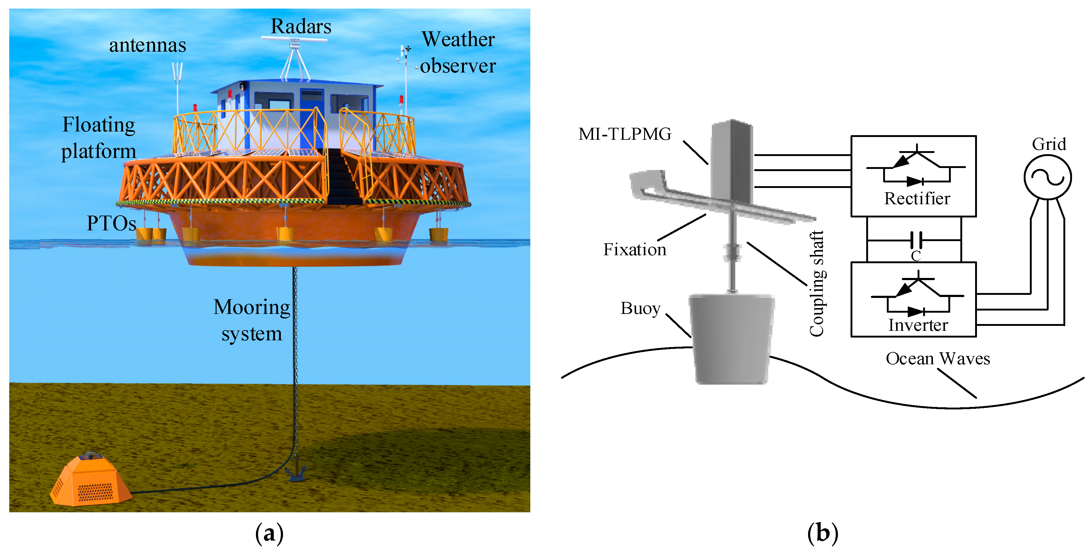
Based on their location, WECs are classified into three subdivisions: onshore, near-shore, and off-shore. According to the depth of ocean, different types of WECs might achieve their best performance in terms of energy absorption. The main source of energy in the offshore WECs is the vertical force component of the waves [22]. Therefore, wave energy conversion systems with floating buoys and platform are preferred off-shore. This paper presents a floating platform WEC for the isolate grids, which includes a floating platform, buoys, MI-TLPMGs, antennas, radars, weather observer, and mooring system, as shown in Figure 1a. The platform can provide location, weather, and communication services for ships on the sea. More importantly, when an emergency occurs on the ship, rescue missions can be performed through radars on the platform. It can be seen that the translator of the MI-TLPMG is directly coupled to the heaving buoy by the shaft and the stator containing windings is mounted on the platform in Figure 1b. Incident waves excite both the buoy and platform in the vertical direction. Nevertheless, in comparison with the buoy, the motion of the floating platform, which is fastened by the anchor, is much smaller, and even could be assumed to be fixed with no motion. Therefore, when the buoy moves along with the waves, the translator will oscillate in the vertical direction. Then, windings mounted in the stator generate electricity. Several power take-offs (PTOs) surround the floating platform on the sea, and all of them supply power to the grid. This special design increases survivability and reliability under extreme weather condition. If some PTOs are destroyed or suffer accidents from ocean waves, the others will provide power to ensure the operation of equipment on the platform. Repair tends to be simple and convenient, and merely needs to replace the broken PTOs.
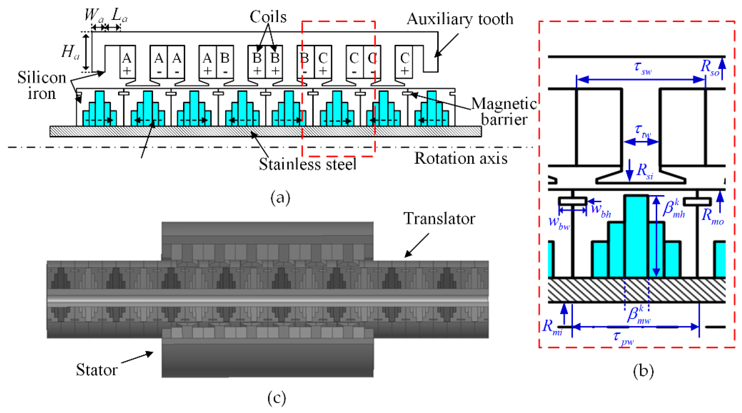
MI-TLPMGs on the platform supply all the equipment by extracting energy from the ocean waves and converting it into electricity. Figure 2 shows a cross section schematic, key geometric parameters, and a 3D structure drawing of MI-TLPMG. It consists of axial magnetization neodymium–iron–boron permanent magnets (PM), stator, translator, coils, auxiliary tooth, stainless steel shaft, and magnetic barrier.
2.2. Theoretical Analysis
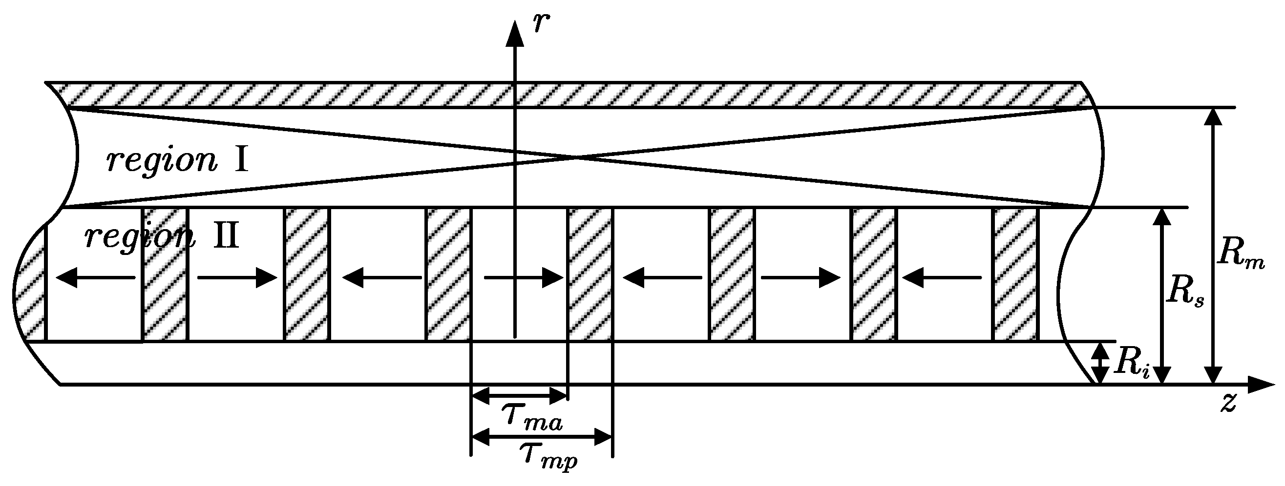
The theoretical analysis of the MI-TLPMG is simplified into a one-layer linear generator in the preliminary design stage to save time and reduce the complexity. For two-dimensional axisymmetric electromagnetic problems of MI-TLPMG, the magnetic field distribution is axially symmetric and periodic in the direction. Therefore, the vector magnetic potential only has the component , and the magnetic field analysis can be divided into two regions: the air gap and winding space (region I) and the permanent magnets space (region II), as shown in Figure 3. The governing equations in terms of the vector magnetic potential are presented as follows [23,24]:
where is the magnetization, is the space permeability, and and are the vector magnetic potentials of region I and region II, respectively. With the consideration of the slot effect in linear permanent magnet machines, the Cater coefficient is applied to calculate the effective air gap as follows [25]:
where , is the slot pitch, is the length of the air gap, is the relative permeability of the PM, and is the radial thickness of magnets. The slotting factor is described as follows:
where is the width of the slot openings. Therefore, the effective length of the air gap and the equivalent translator radius are given by:
where is the outer radius of the translator. The terminal voltage for a phase can be expressed as:
where is the phase resistance; and are the phase current and inductance, respectively; is the flux linkage in the phase; and is the number of coil turns per phase. The total iron loss in the machine comprises hysteresis and eddy current losses and is calculated as follows [26]:
where is the hysteresis loss; is the eddy current loss; is the total iron loss; is the magnetic flux density at frequency order ; is the maximum frequency order; and are the hysteresis loss and eddy current loss coefficient; , , and are empirical coefficients; is the volume of each element; and is the number of elements. In this analysis, electromagnetic losses are considered as the combination of winding copper losses and distributed iron losses from FEA. Copper loss can be calculated by using
where is the copper loss and is the effective value of the winding current. Frequency-dependent resistance changes are neglected in this study. The slow waves lead the generator to operate under the condition of low speed. Hence, the eddy current loss can be neglected. Finally, the efficiency of the generator in this paper is shown as follows:
where is the total output power of the machine (W). The friction loss and windage loss are neglected in the following simulation studies because they only account for a tiny fraction of the total loss.
2.3. Comparative Machines and Design Parameters
The rough size of the generator can be determined by the above electromagnetic analysis, but the precise model is analyzed by FEA. A series of physical changes are applied to the translator and stator geometry of MI-TLPMG to optimize the electromagnetic performance. Because the space and volume for the generators on the floating platform is limited, the purpose of the optimized design parameters is to output as much more power as possible in the same volume and meet the power supply requirement of the equipment on the platform. The work presented here gives a detail analysis of the considered machine, including maximizing the back-EMF, reducing the cogging force, calculating the loss and efficiency, etc. Some other performance investigations are fulfilled to obtain the final model. For a fair comparison, some rules and constraints are listed as follows:
- The translator inner radius, stator outer radius, and armature length of the two machines are the same. Moreover, the two machines are designed and optimized to get the best electrical performance under the same ocean wave speed and load condition.
- The material properties, i.e., permanent magnets, wire gauge, and iron type used in the translator and stator are also identical. The translator is made up of neodymium–iron–boron PMs (NdFe38M), with T, , and KA/m. The material of the stator is steel Q235A, which is commonly used and has a high saturation point.
The cross-sectional diagram, key geometric parameters, and 3D structure schematic are shown in Figure 2. The RS-TLPMG and QH-Halbach, which have been applied to WECs in [27] and [13], are compared with MI-TLPMG in this paper. The crucial specifications and parameters of MI-TLPMG, RS-TLPMG, and QH-TLPMG are listed in Table 1.
3. Comparative Performance Analysis
3.1. Air Gap Magnetic Flux Density and Magnetic Field Distribution
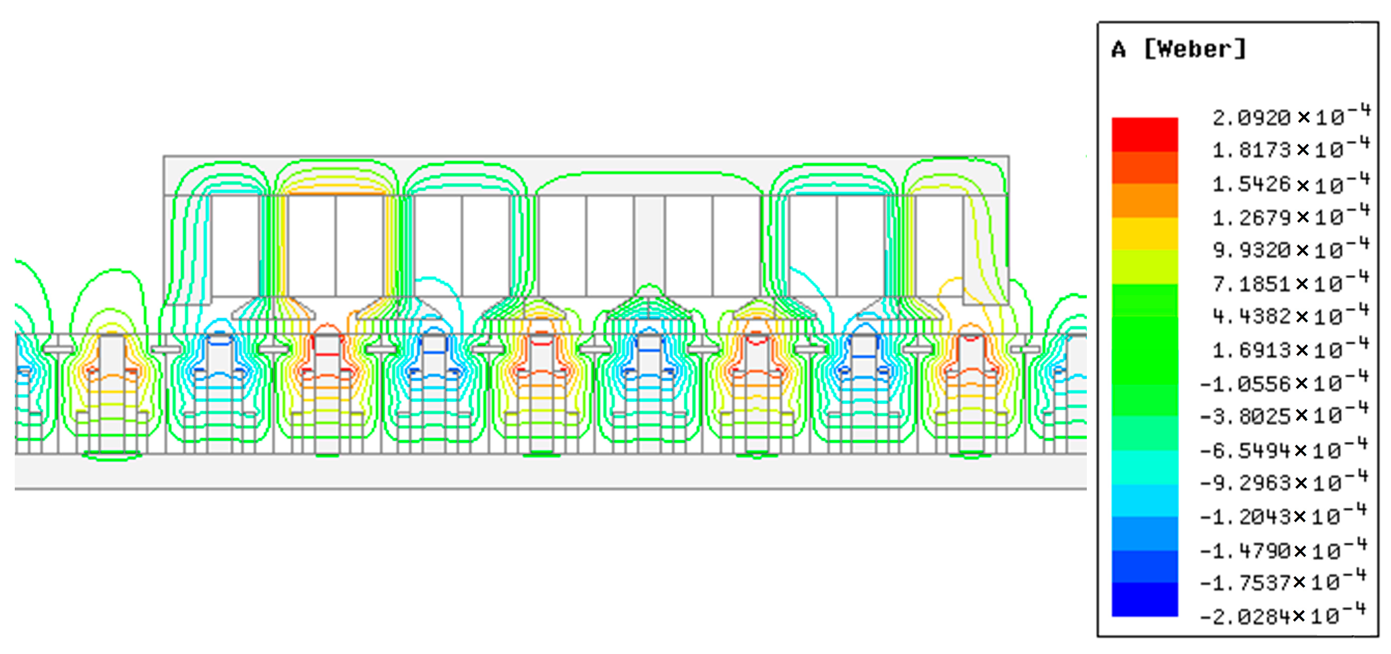
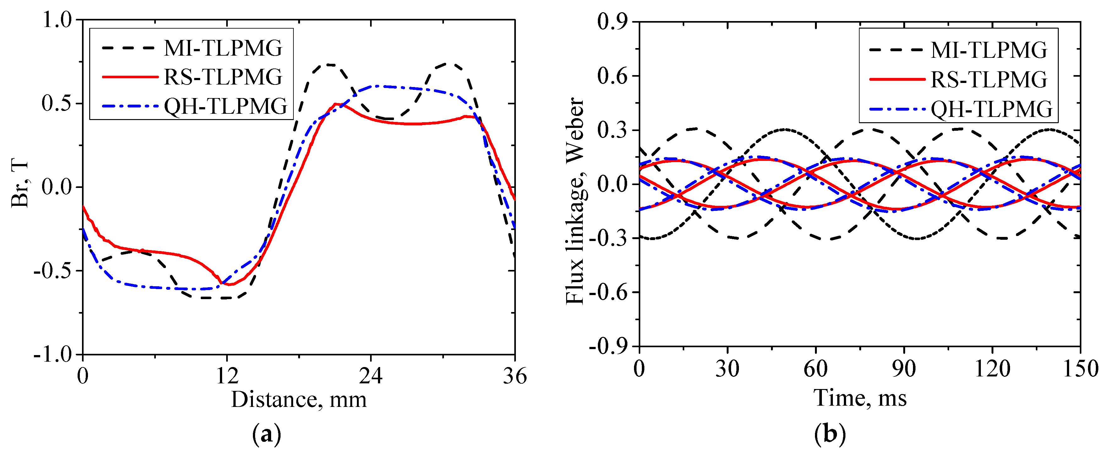
Air gap magnetic flux density is a crucial parameter for the generator design and will affect the flux linkage of each winding. The magnetic field distribution on the no-load condition is depicted in Figure 4. It can be seen that the flux lines pass through the magnet layers and concentrate in the air gap between the stator and translator. This flux concentrating effect will increase the magnetic flux density as shown in Figure 5a. The air gap magnetic flux density for MI-TLPMG is 0.75 T, which is improved about 1.56 times from the 0.48 T for RS-TLPMG and 1.27 times from the 0.59 T for QH-TLPMG. Similarly, the flux linkage amplitude of the MI-TLPMG is the largest among the three machines, and is about 2.3 times that of the RS-TLPMG, as shown in Figure 5b. Therefore, the performance of MI-TLPMG is much better than those of RS-TLPMG and QH-TLPMG in terms of both the air gap magnetic flux density and the flux linkage.
3.2. Performance Analysis at a Constant Speed
Under real oceanic conditions, the speed of waves is not a constant value. Consequently, the direct-drive WEC system is a nonuniform motion. In order to facilitate the analysis of the generators, the speed of the translator is assumed to be a constant value in the initial design stage, i.e., 0.4 m/s. The back-EMF, load performance, output power, and efficiency of the three machines are investigated and compared by using FEA in this section.
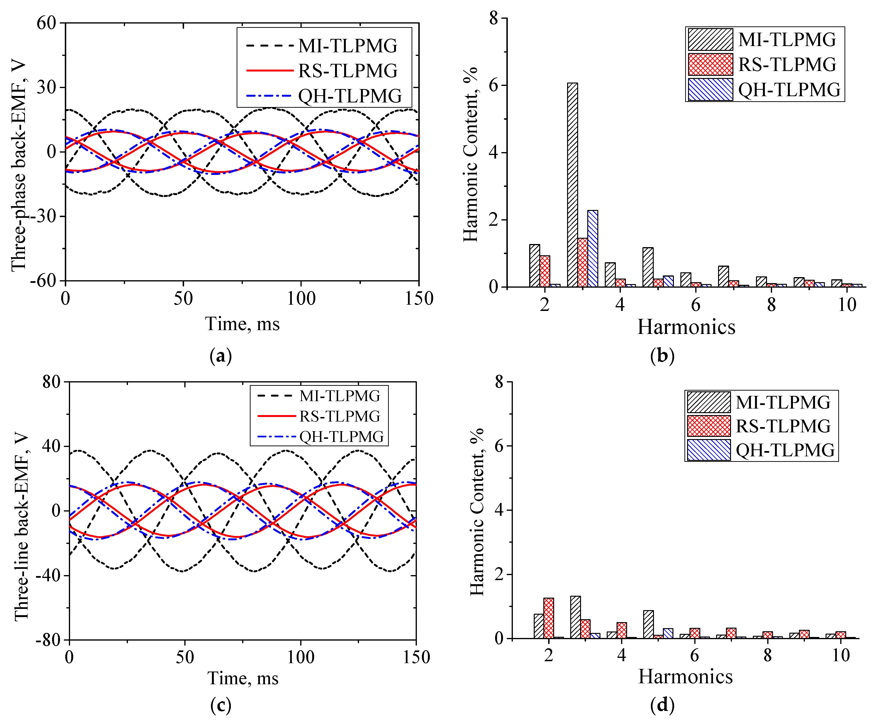
Figure 6 shows the phase and line open-circuit back-EMF of MI-TLPMG, RS-TLPMG, and QH-TLPMG at the constant speed of 0.4 m/s. As shown in Figure 6a, the no-load phase back-EMFs are approximately sinusoid and are symmetric with each other. This validates the correctness of the machine design. The phase back-EMF amplitudes of MI-TLPMG, RS-TLPMG, and QH-TLPMG are about 20 V, 9.5 V, and 10.5 V, respectively. This indicates that the back-EMF of MI-TLPMG is significantly higher than that of the other machines. Based on the Fourier analysis, Figure 6b shows a high three-order harmonic existing in the phase back-EMF of MI-TLPMG. However, the three-order harmonic could be eliminated by employing star-connection armature windings as shown in Figure 6d. Then, from Figure 6c, it can be seen that the line back-EMF waveform of the MI-TLPMG is more sinusoidal and the total harmonic distortion (THD) of the back-EMF is less than 1.9%.
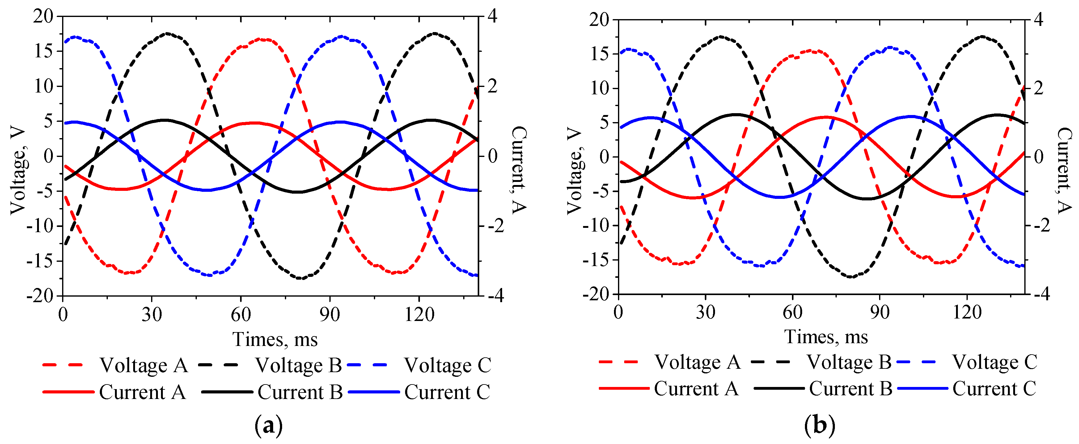
In order to investigate the load performance of the machine, three-phase resistance and resistance–inductance loads were applied to MI-TLPMG. Figure 7a shows that the maximum values of voltage and current are 17.5 V and 1 A, respectively, at the speed of 0.4 m/s. It can be seen that there is a phase offset of 20 degrees between the voltage and current waveforms for the load R = 12 Ω and L = 100 mH, as shown in Figure 7b. Moreover, the peak value of the Phase B is 17.2 V, which is much greater than other phases. The main reasons for this phenomenon are the windings arrangement and the armature reaction caused by the load current. For MI-TLPMG, Phase A and Phase C are arranged at the ends of the stator, whereas Phase B is at the center, as depicted in Figure 2a. Because of the finite stator, the magnetic flux lines that pass through Windings A and C are much less than through Winding B; hence, the values of induced phase voltage are smaller.
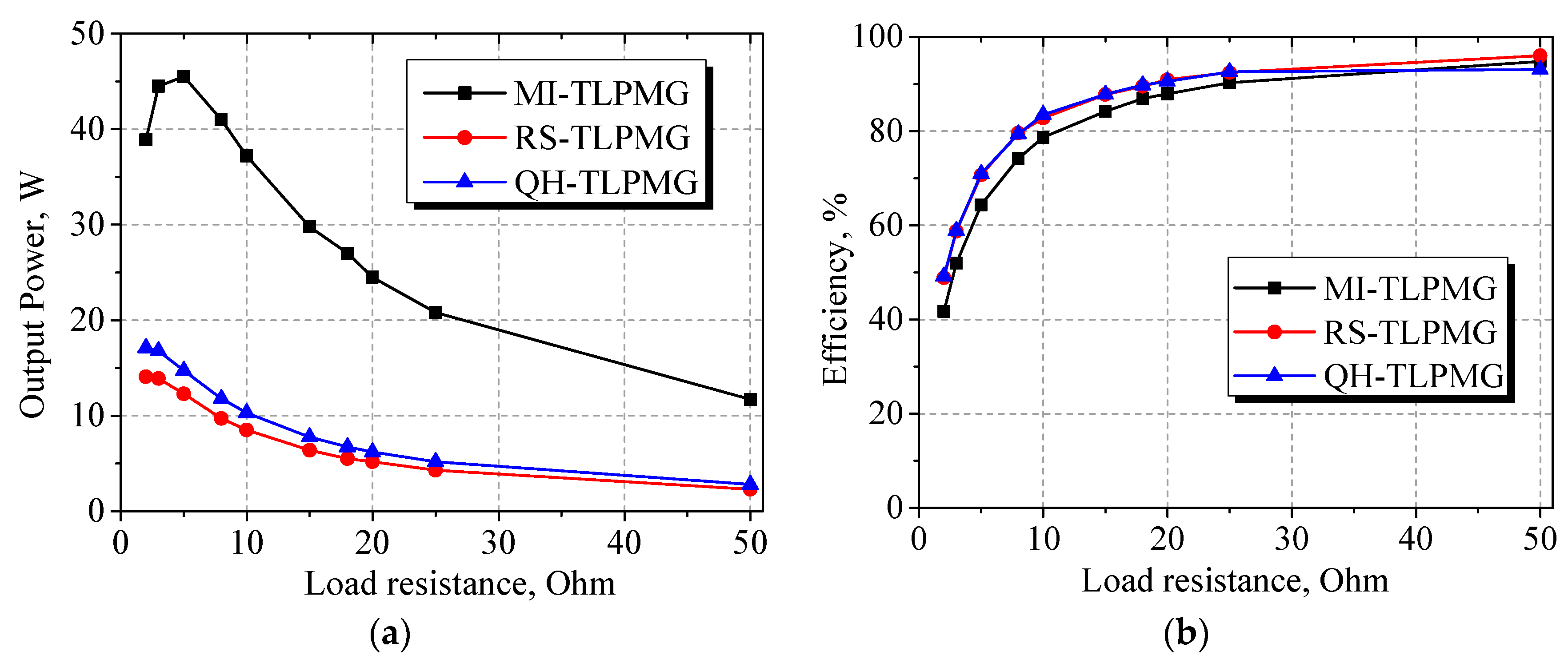
Power density and force capability are key characteristics of linear generators for ocean wave energy conversion systems. Generally, if different generators are designed in an identical volume, the one which has higher power density will convert more wave energy into electricity at the same wave speed. In order to capture energy as much as possible, the power density must be enhanced. Figure 8a shows the output power values and efficiency at different resistance loads for MI-TLPMG, RS-TLPMG, and QH-TLPMG, separately. With the increment of the resistance load, the output power of both machines decreases gradually, whereas the trend of efficiency is opposite. The maximum value of output power for MI-TLPMG is 46 W, which is about 3.3 times that of RS-TLPMG under the same volume in Figure 8a. On the full-load condition of 15 Ω, the output power is about 31 W. Based on Equation (11) in Section 2.2, the efficiency of the MI-TLPMG, RS-TLPMG, and QH-TLPMG can be obtained as follows. From Figure 8b, it can be seen that efficiency for MI-TLPMG is up to 88.3% when the resistance is 20 Ω.
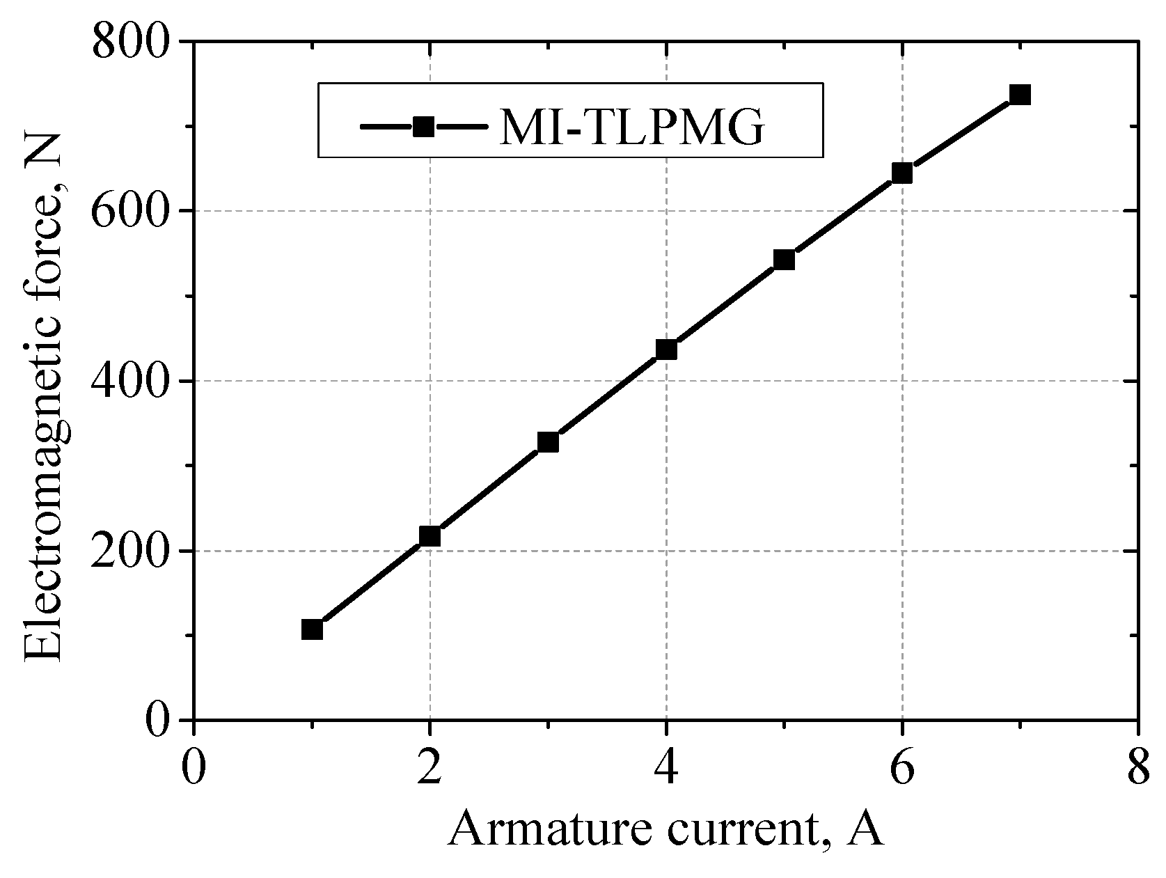
For wave energy converters, the electromagnetic force of the generators could influence the operation of the system. Therefore, the maximum force capacity of MI-TLPMG is analyzed under different armature currents as shown in Figure 9. It can be seen that the electromagnetic force is in proportion to the armature current.
3.3. Performance Analysis at a Sinusoidal Speed
The above analysis is under the constant speed of 0.4 m/s for the purpose of simplicity; nevertheless, the motion of generators is complex and nonlinear in real WEC systems. The buoy designed for the experiment is cylindrical and moves along with the incident ocean waves in the vertical direction. As only the regular waves are applied, the wave height and period are assumed to be and , respectively, where and are the amplitude and angular frequency of the wave, respectively. The surface elevation equation of the incident wave can be described as
Consequently, the translator speed of the generator in an ideal situation, which neglects inertia, friction, wave reflection, and some other effects, is assumed as follows:
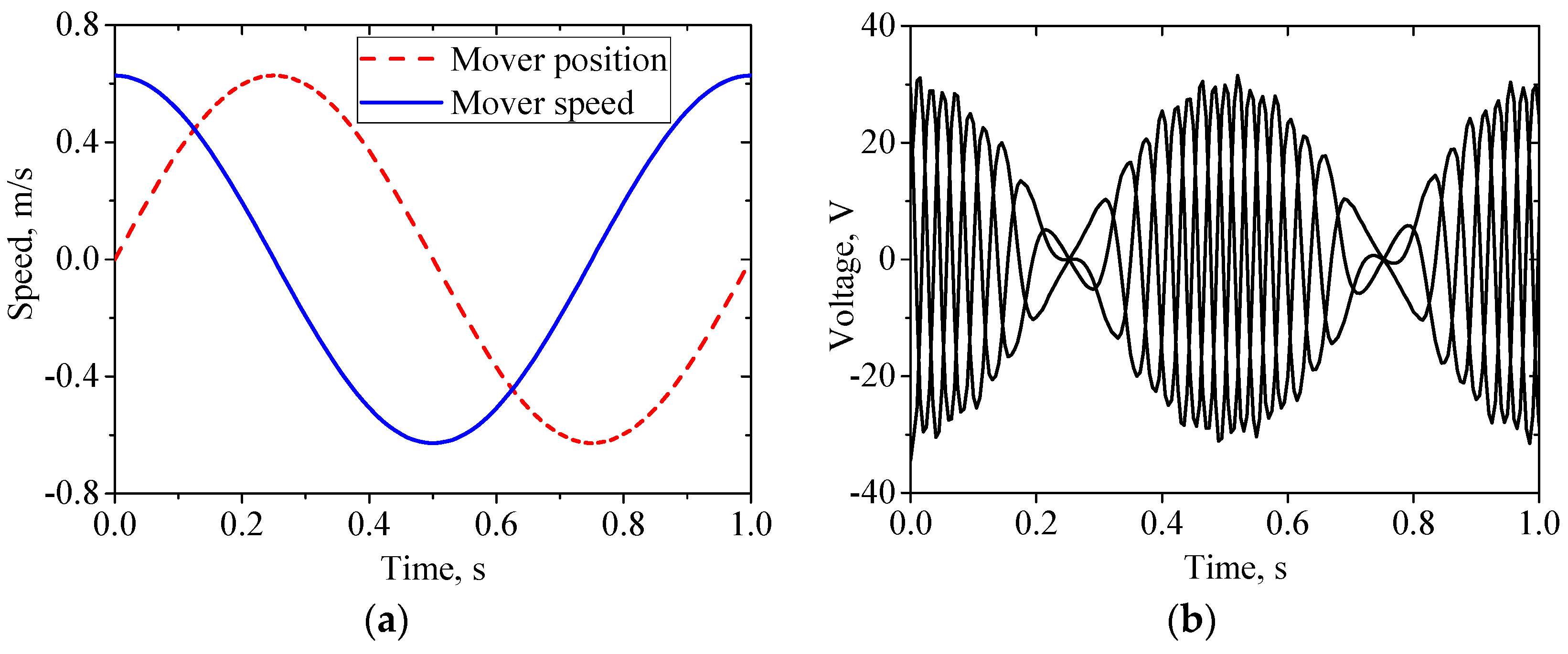
In the following experiment, a wave of m and s is adopted to measure the performance of MI-TLPMG. Hence, the corresponding sinusoidal speed is applied in the translator. It is known that the root mean square of this speed is 0.4 m/s, which was used in the previous constant speed analysis. Figure 10a shows the position and velocity of the translator in the ocean circumstance. The peak value of back-EMF is up to 32.4 V at the sinusoidal speed in Figure 10b. When the translator passes the zero point of position, the voltage reaches the maximum value and then decreases to zero gradually.
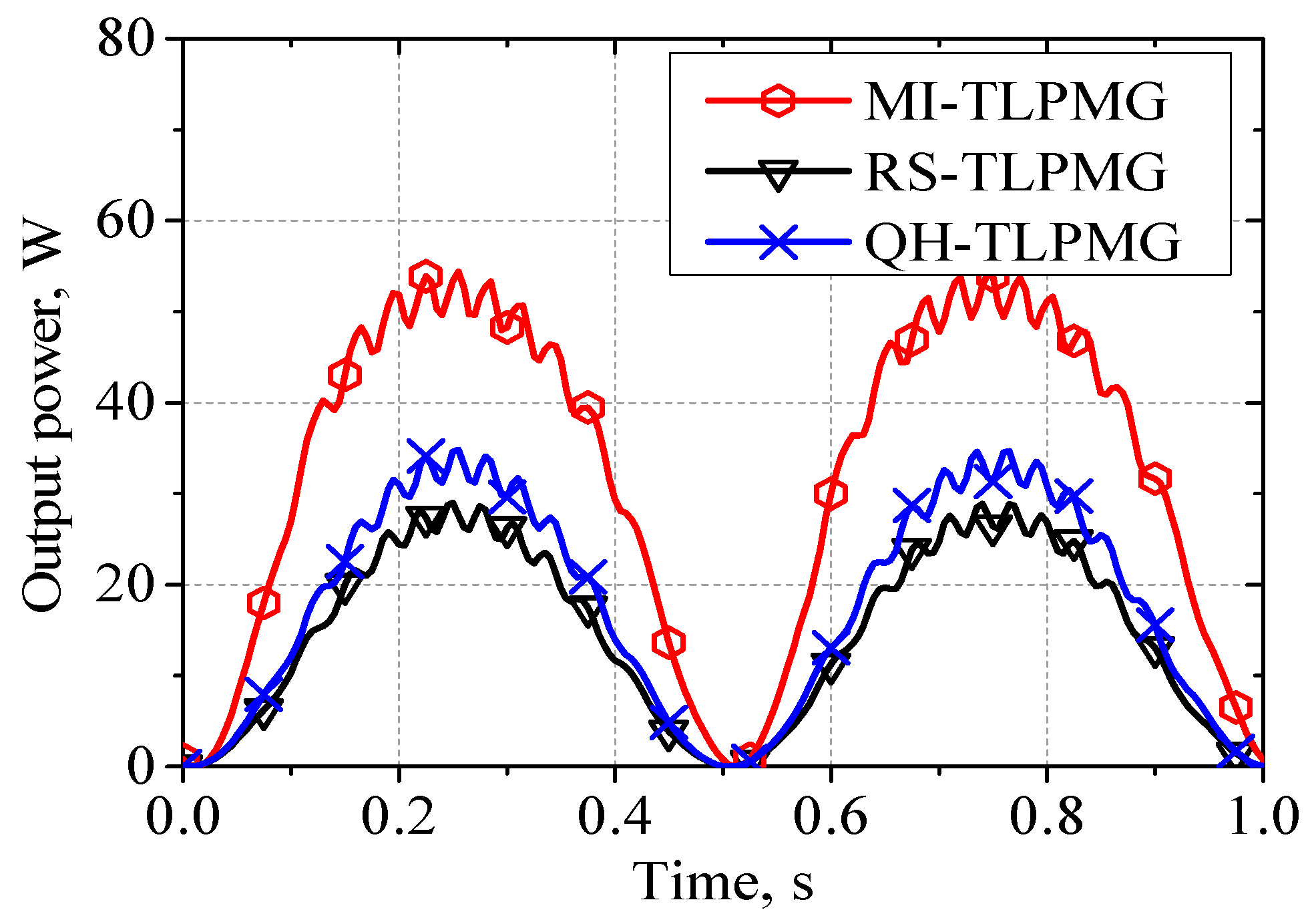
Figure 11 shows the instantaneous output power of MI-TLPMG, RS-TLPMG, and QH-TLPMG for 2 Ω load at a sinusoidal speed of . When the translator reaches the maximum speed, the peak output power values of the three generators are 55 W, 24 W, and 33 W, respectively. Therefore, the output power of MI-TLPMG is about 2.3 times that of RS-TLPMG. It is observed that the instantaneous output power is not a stable value because of the varying incident ocean wave speed. The poor-quality electricity cannot be used directly to supply the equipment and sensors on the floating platform. It must be modulated by AC–DC and DC–AC circuits, then ultimately meet the requirements of equipment in terms of voltage and frequency.
3.4. Cogging Force
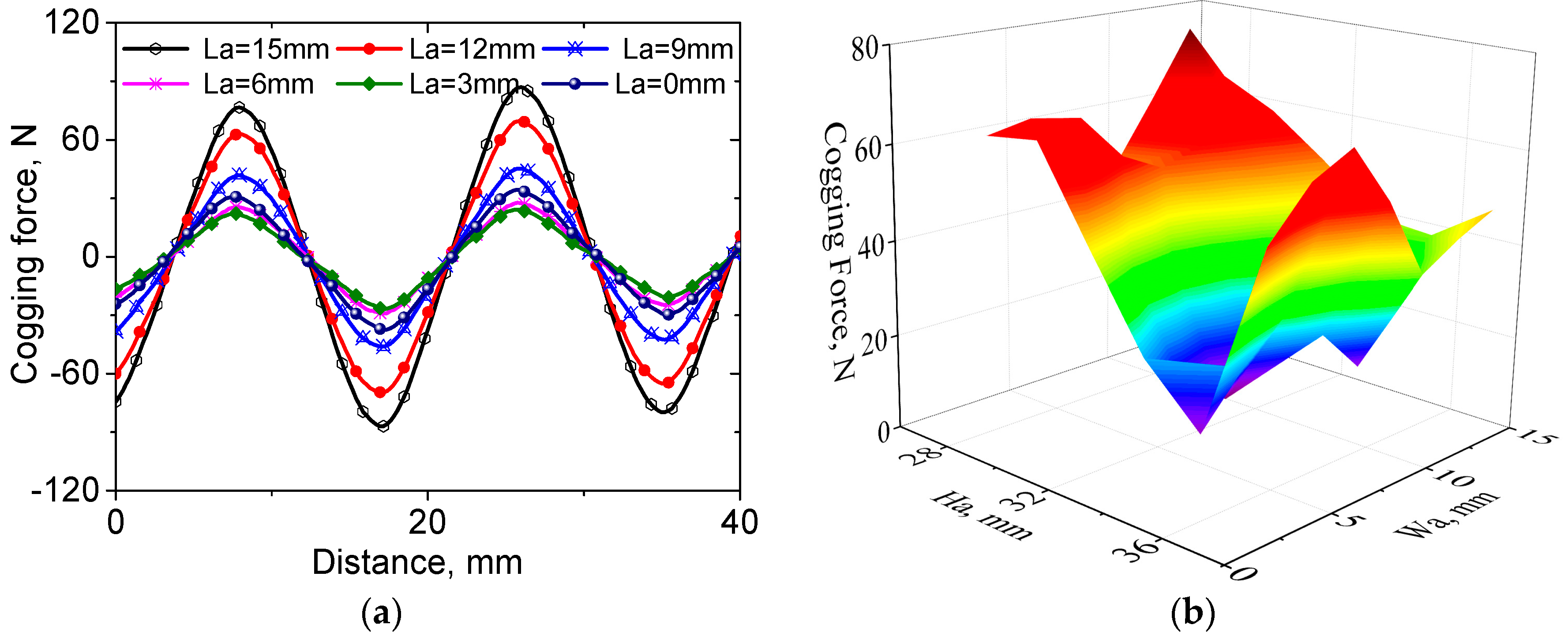
Irregular air gap magnetic permeance, which is caused by the teeth-slot alternation and the finite stator length, gives rise to cogging force in the generator. This force brings about a serious mechanical vibration, which makes the generation more difficult to work, especially under the condition of low ocean wave speed. Furthermore, the speed fluctuation induced by the cogging force will make the output power quality much more difficult to utilize. Many methods have been applied to reduce the cogging force such as skewed PMs, semiclosed stator slots, pole-shifting, etc. [28,29]. In this section, the optimization of the auxiliary tooth is applied to reduce the cogging force. The main geometric parameters of the auxiliary tooth, which have an impact on the cogging force, are the prominent length La, width Wa, and height Ha as shown in Figure 2a. Figure 12a shows that the cogging force changes significantly with values of La. The maximum value is up to 87 N while the prominent length (La) is 15 mm. It can be seen that the value of the cogging force is 26.5 N while La is 3 mm, which means 70% of the cogging force is reduced by changing the prominent length. Then, the width Wa and height Ha of the auxiliary tooth are changed synchronously and the results are shown in Figure 12b. It is observed that the optimal value of the cogging force is 9.5 N on the condition of Wa = 7 mm and Ha = 33 mm. Compared with the value achieved by optimizing La, the cogging force is about 3 times smaller.
4. Experiment Analysis
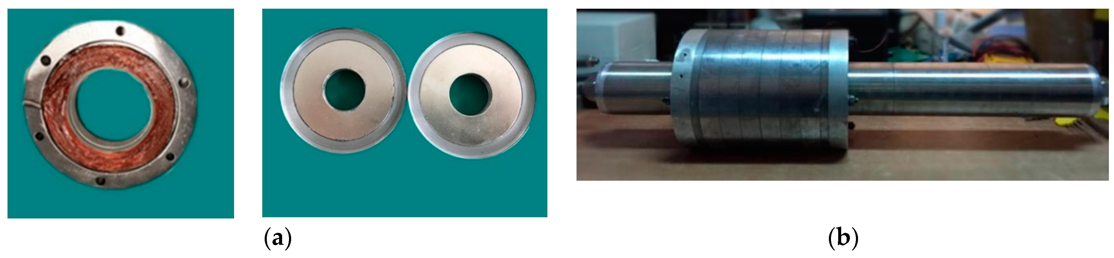
As shown in Figure 13, an MI-TLPMG was manufactured to verify the results of the above analysis. The detailed specifications and key design parameters of the prototype are the same as those listed in Table 1. Figure 13a shows a part of the stator with coils and the permanent magnet layers of the translator. The full view of the manufactured MI-TLPMG is shown in Figure 13b.
4.1. Experiments on the Test Platform
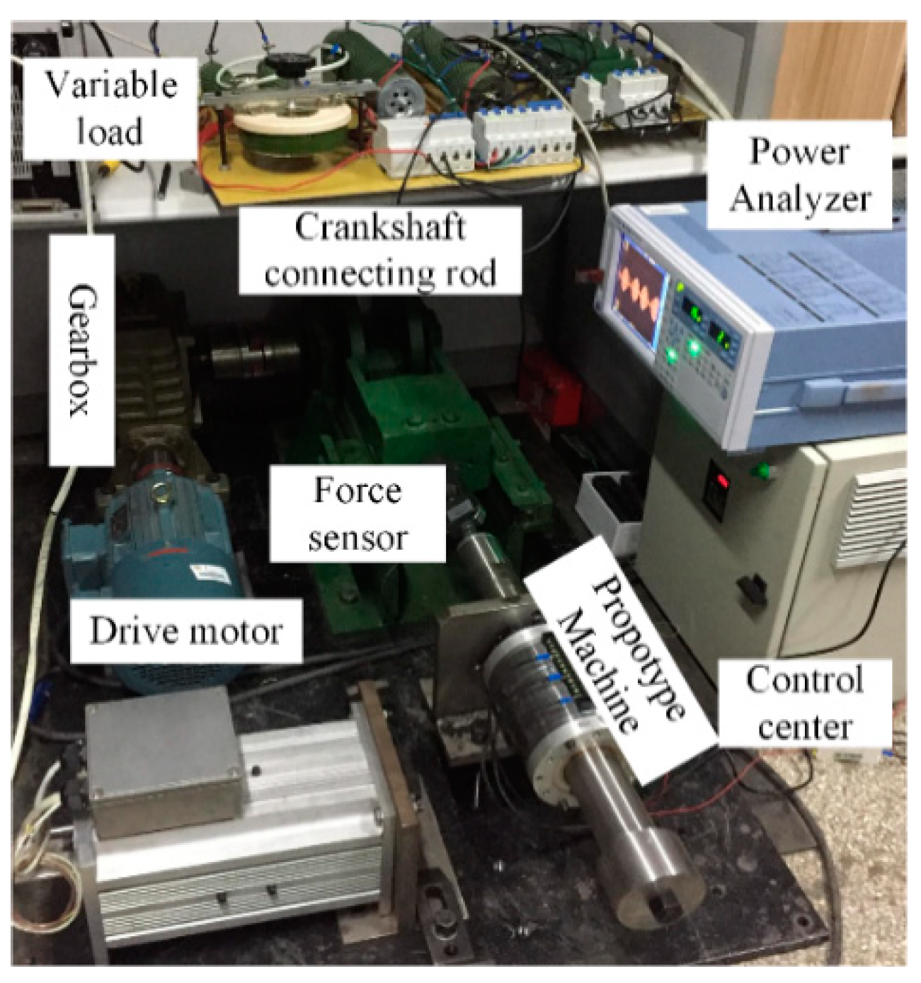
When the prototype was manufactured, the performance of MI-TLPMG was measured on the test platform. The test platform consisted of a motor, gearbox, crankshaft connecting rod, sensors, prototype machine, power analyzer, loads, etc., as shown in Figure 14. The speed of the driving motor is too high to simulate the actual ocean wave movement. Therefore, a gearbox was applied in the platform to reduce the speed and enhance the output torque. Furthermore, the ocean wave is a linear motion while the motor is rotary. In order to translate the movement to linear motion, a crankshaft with a stroke of 0.2 m was used to connect the gearbox and prototype generator. This design makes the MI-TLPMG operate continuously at different sinusoidal speeds in the linear motion.
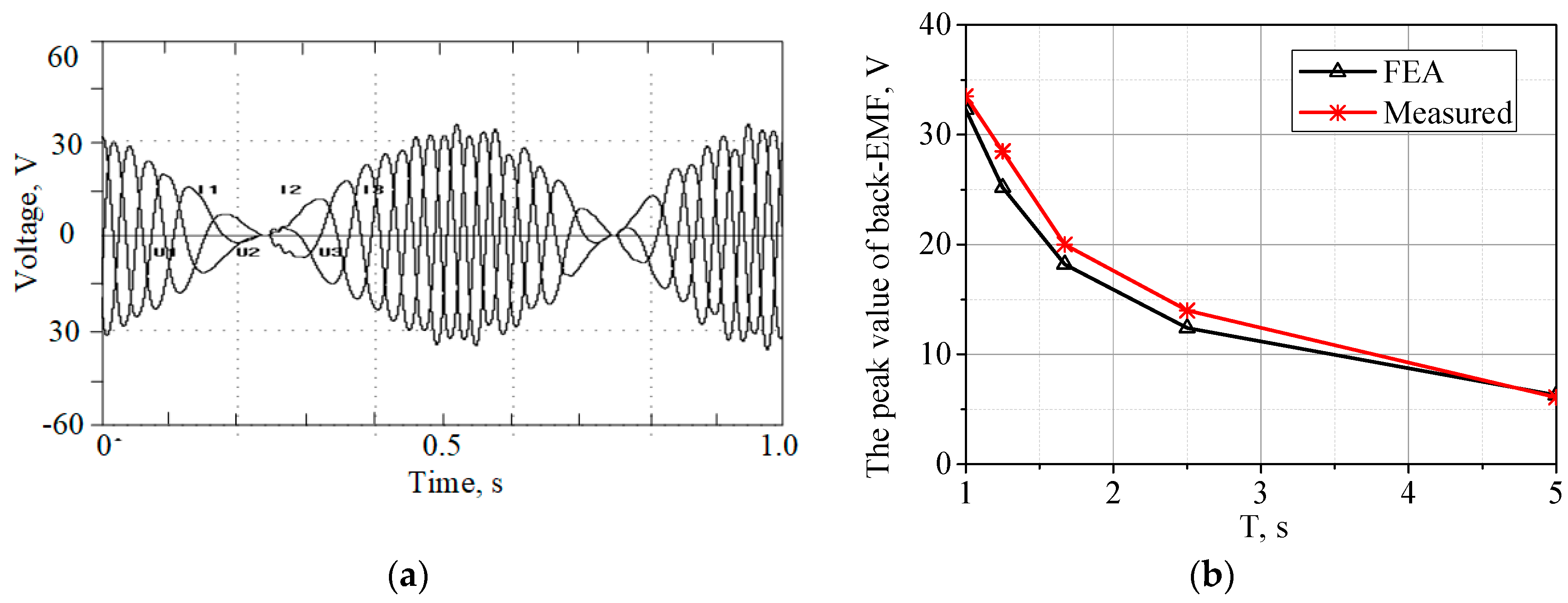
Table 2 lists the different periods adopted to produce sinusoidal speeds, which are used to analyze the performance of MI-TLPMG at various resistance loads. The measured three-phase back-EMF waveforms for MI-TLPMG at a sinusoidal speed of 0.63 cos(2πt) are given in Figure 15a. It can be found that the measured back-EMF waveforms have a great agreement with the FEA results in Figure 10b. The peak voltage values of measured and FEA results are 33.4 V and 31.2 V, respectively. The experiment results of back-EMF for MI-TLPMG at different periods are shown in Figure 15b.
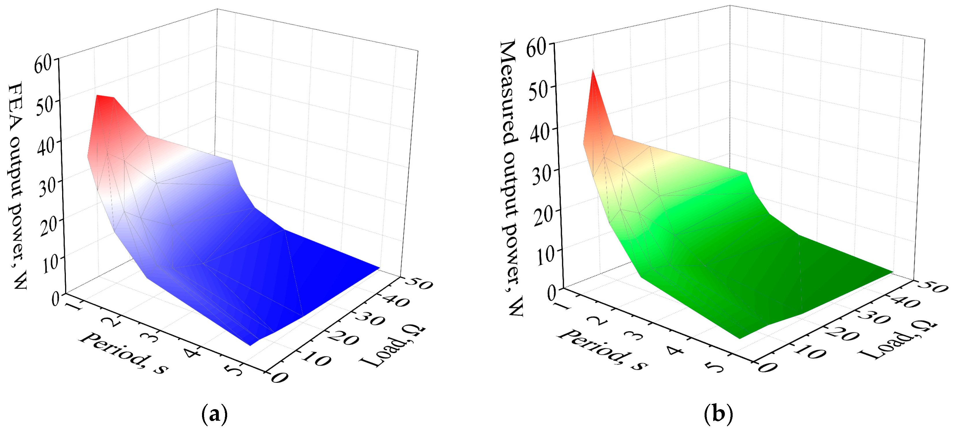
Then, the performance of different sinusoidal speeds, as listed in Table 2, with various loads was investigated on the test platform. Figure 16 shows the measured average output power at different periods on the condition of 2 Ω to 50 Ω, as well as compared with FEA results. It is observed that the measured average output power values have the same changing trend with FEA results. In addition, the maximum values of the measured and FEA results are 54 W and 51.4 W, respectively, which shows a good agreement with each other.
4.2. Experiments in the Wave Tank
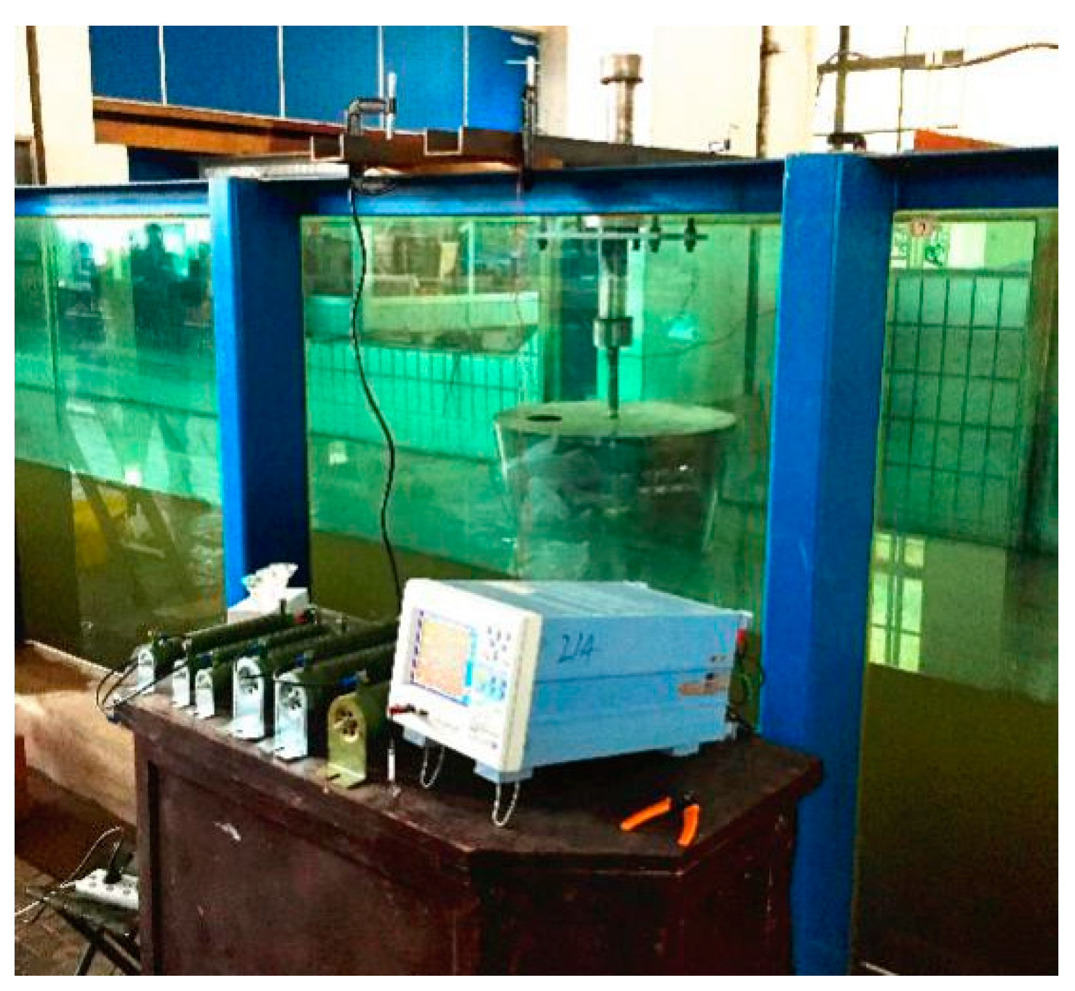
After the platform tests, an experiment was conducted in the wave tank to verify the feasibility of whether the designed MI-TLPMG could be applied in an ocean wave conversion system, as shown in Figure 17. The length, depth, and width of wave tank are 50 m, 1 m, and 1 m, respectively. From a wave maker at the end of the tank, monochromatic waves with different heights and periods are produced to simulate the ocean waves. The stator of the MI-TLPMG was fixed by the steel frame, which was attached to the wave tank with bench clamps. Meanwhile, the translator was firmly connected to the buoy with a stainless steel shaft. Incident ocean waves drive the buoy and translator in the vertical direction; however, the stator remains stationary. Therefore, the relative speed between translator and stator induces electricity in the windings. The dimension and mass of the buoy are listed in Table 3. The radius, height, and thickness were 0.3 m, 0.5 m, and 0.001 m, respectively. The mass of it, which was made up with stainless steel, was 11.7 kg. The height ratio between the buoy and wave was 0.5 while the wave height was 0.25 m.
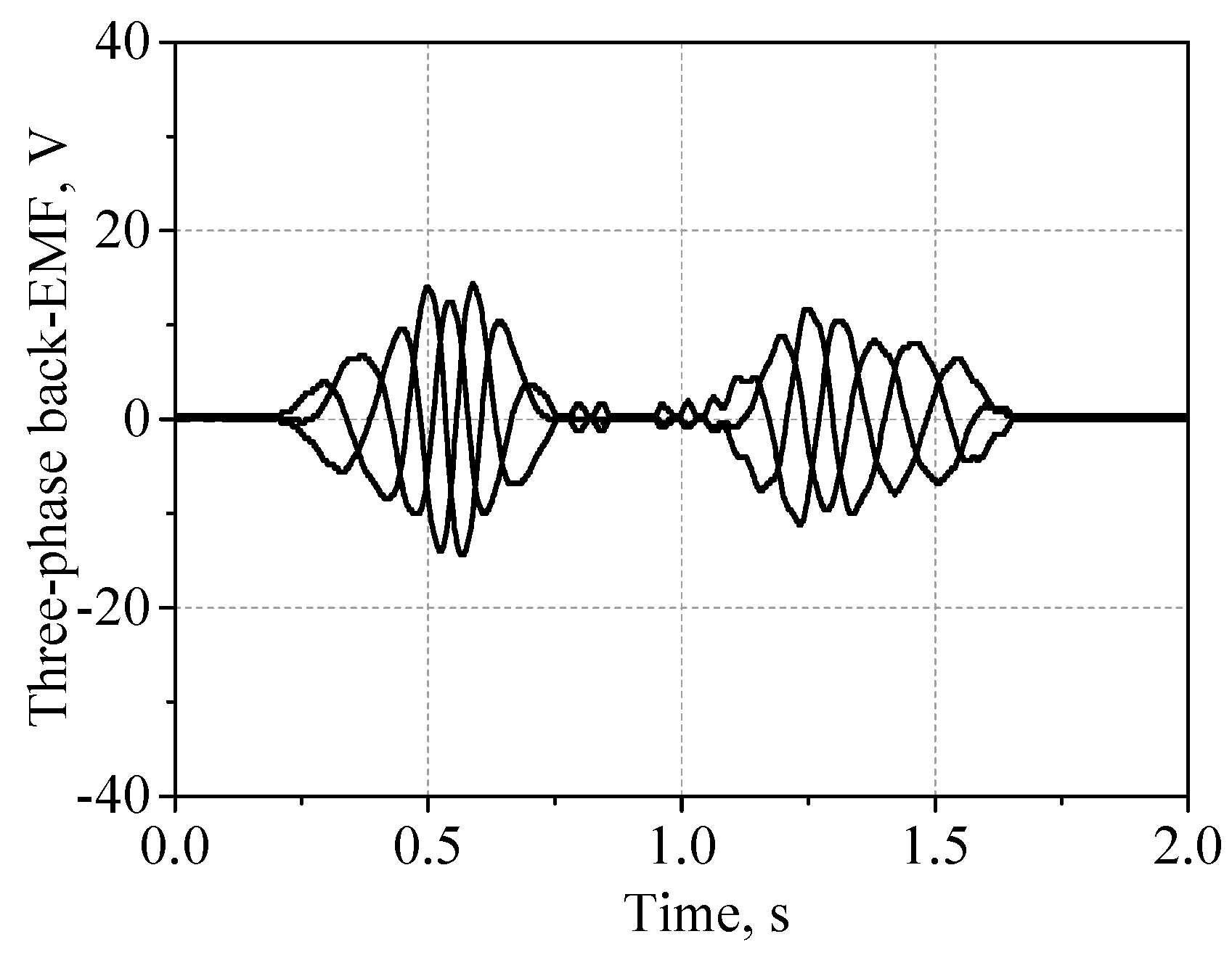
In the experiment, the wave maker produced monochromatic waves with different periods and heights. The applied wave height H and period T were 0.25 m and 2 s, respectively. Figure 18 shows the three-phase back-EMF waveforms in a period of time. It can be seen that the peak value of the waveforms is 14.4 V, which is less than the FEA-calculated result of 18.4 V. On the one hand, a main reason for this is that the floating buoy and waves are not at a perfect resonant state, which means that the wave energy could not be maximally absorbed and converted. On the other hand, the interaction between the waves and buoys in motion leads a part of wave energy to be lost in the form of breakers and the friction is neglected in the FEA calculation, which has been declared in the previous section.
5. Conclusions
In this paper, a tubular linear generator with multilayer interior permanent magnets, which is attractive for WEC systems, was presented, analyzed, manufactured, and tested in detail. Using finite element analysis (FEA), a comparative and exhaustive study among the proposed MI-TLPMG, RS-TLPMG, and QH-TLPMG was fulfilled. The analysis and experiments indicate that MI-LTPMG with its flux-concentrating effect has excellent performance in magnetic flux density, flux linkage, back-EMF, and output power compared with RS-TLPMG and QH-TLPMG in the same volume. The cogging force of MI-TLPMG was minimized in order to reduce mechanical vibration. Finally, a prototype of MI-TLPMG was manufactured and measured on a test platform and wave tank. The experiment and simulation results show a great agreement with each other. Therefore, the proposed MI-TLPMG is feasible and suitable for WEC systems.
Author Contributions
All the authors have contributed their efforts to complete the paper. H.Y. supervised the work. T.X. and Z.S. conducted the simulation and experiment parts. R.G. analyzed the experiment results.
Acknowledgments
This work was supported by the Natural Science Foundation of China (No. 41576096), the Fundamental Research Funds for the Central Universities and Postgraduate Research & Practice Innovation Program of Jiangsu Province (No. KYCX17_0083).
Conflicts of Interest
The authors declare no conflict of interest.
References
- Falcão, A.F.O.; Henriques, J.C.C. Oscillating-water-column wave energy converters and air turbines: A review. Renew. Energy 2016, 85, 1391–1424. [Google Scholar] [CrossRef]
- Chen, H.; Tang, T.; Aït-Ahmed, N.; Benbouzid, M.E.H.; Machmoum, M.; Zaïm, M.E.H. Attraction, Challenge and Current Status of Marine Current Energy. IEEE Access 2018, 6, 12665–12685. [Google Scholar] [CrossRef]
- Penalba, M.; Ringwood, J.V. A Review of Wave-to-Wire Models for Wave Energy Converters. Energies 2016, 9, 506. [Google Scholar] [CrossRef]
- Falcão, A.F.O. Wave energy utilization: A review of the technologies. Renew. Sustain. Energy Rev. 2010, 14, 899–918. [Google Scholar] [CrossRef]
- Astariz, S.; Iglesias, G. The economics of wave energy: A review. Renew. Sustain. Energy Rev. 2015, 45, 397–408. [Google Scholar] [CrossRef]
- Sun, K.; Ge, W.; Luo, L.; Liang, H.; Xu, C.; Leng, J.; Yuan, Z.; Huang, H. Research on the hydraulic power take-off unit of a hybrid wave energy converter. In Proceedings of the OCEANS 2016-Shanghai, Shanghai, China, 10–13 April 2016. [Google Scholar]
- Gaspar, J.F.; Calvário, M.; Kamarlouei, M.; Guedes Soares, C. Power take-off concept for wave energy converters based on oil-hydraulic transformer units. Renew. Energy 2016, 86, 1232–1246. [Google Scholar] [CrossRef]
- Xiao, X.; Huang, X.; Kang, Q. A Hill-Climbing-Method-Based Maximum-Power-Point-Tracking Strategy for Direct-Drive Wave Energy Converters. IEEE Trans. Ind. Electron. 2016, 63, 257–267. [Google Scholar] [CrossRef]
- Huang, L.; Hu, M.; Yu, H.; Liu, C.; Chen, Z. Design and experiment of a direct-drive wave energy converter using outer-PM linear tubular generator. IET Renew. Power Gener. 2017, 11, 353–360. [Google Scholar] [CrossRef]
- Huang, L.; Hu, M.; Chen, Z.; Yu, H.; Liu, C. Research on a Direct-Drive Wave Energy Converter Using an Outer-PM Linear Tubular Generator. IEEE Trans. Magn. 2017, 53, 8104704. [Google Scholar] [CrossRef]
- Polinder, H.; Mecrow, B.C.; Jack, A.G.; Dickinson, P.G.; Mueller, M.A. Conventional and TFPM linear generators for direct-drive wave energy conversion. IEEE Trans. Energy Convers. 2005, 20, 260–267. [Google Scholar] [CrossRef]
- Du, Y.; Cheng, M.; Chau, K.T.; Liu, X.; Xiao, F.; Zhao, W. Linear primary permanent magnet vernier machine for wave energy conversion. IET Electr. Power Appl. 2015, 9, 203–212. [Google Scholar] [CrossRef]
- Liu, C.; Yu, H.; Liu, Q.; Zhong, W.; Zhu, H. Research on a double float system for direct drive wave power conversion. IET Renew. Power Gener. 2017, 11, 1026–1032. [Google Scholar] [CrossRef]
- Vermaak, R.; Kamper, M.J. Design Aspects of a Novel Topology Air-Cored Permanent Magnet Linear Generator for Direct Drive Wave Energy Converters. IEEE Trans. Ind. Electron. 2012, 59, 2104–2115. [Google Scholar] [CrossRef]
- Feng, N.; Yu, H.; Hu, M.; Liu, C.; Huang, L.; Shi, Z. A Study on a Linear Magnetic-Geared Interior Permanent Magnet Generator for Direct-Drive Wave Energy Conversion. Energies 2016, 9, 487. [Google Scholar] [CrossRef]
- Niu, S.; Ho, S.L.; Fu, W.N. Performance Analysis of a Novel Magnetic-Geared Tubular Linear Permanent Magnet Machine. IEEE Trans. Magn. 2011, 47, 3598–3601. [Google Scholar] [CrossRef]
- Holehouse, R.C.; Atallah, K.; Wang, J. Design and Realization of a Linear Magnetic Gear. IEEE Trans. Magn. 2011, 47, 4171–4174. [Google Scholar] [CrossRef]
- Li, J.; Yang, Q.; Robinson, F.; Liang, F.; Zhang, M.; Yuan, W. Design and test of a new droop control algorithm for a SMES/battery hybrid energy storage system. Energy 2017, 118, 1110–1122. [Google Scholar] [CrossRef]
- Nie, Z.; Xiao, X.; Kang, Q.; Aggarwal, R.; Zhang, H.; Yuan, W. SMES-Battery Energy Storage System for Conditioning Outputs From Direct Drive Linear Wave Energy Converters. IEEE Trans. Appl. Supercond. 2013, 23, 5000705. [Google Scholar] [CrossRef] [Green Version]
- Kovaltchouk, T.; Blavette, A.; Aubry, J.; Ahmed, H.B.; Multon, B. Comparison Between Centralized and Decentralized Storage Energy Management for Direct Wave Energy Converter Farm. IEEE Trans. Energy Convers. 2016, 31, 1051–1058. [Google Scholar] [CrossRef]
- MagNet. Available online: https://www.mentor.com/products/mechanical/magnet/magnet/ (accessed on 1 June 2018).
- Ghasemi, A.; Anbarsooz, M.; Malvandi, A.; Ghasemi, A.; Hedayati, F. A nonlinear computational modeling of wave energy converters: A tethered point absorber and a bottom-hinged flap device. Renew. Energy 2017, 103, 774–785. [Google Scholar] [CrossRef]
- Wang, J.; Jewell, G.W.; Howe, D. A general framework for the analysis and design of tubular linear permanent magnet machines. IEEE Trans. Magn. 1999, 35, 1986–2000. [Google Scholar] [CrossRef] [Green Version]
- Amara, Y.; Barakat, G. Analytical Modeling of Magnetic Field in Surface Mounted Permanent-Magnet Tubular Linear Machines. IEEE Trans. Magn. 2010, 46, 3870–3884. [Google Scholar] [CrossRef]
- Gysen, B.L.J.; Meessen, K.J.; Paulides, J.J.H.; Lomonova, E.A. General Formulation of the Electromagnetic Field Distribution in Machines and Devices Using Fourier Analysis. IEEE Trans. Magn. 2010, 46, 39–52. [Google Scholar] [CrossRef] [Green Version]
- Toulabi, M.S.; Salmon, J.; Knight, A.M. Concentrated Winding IPM Synchronous Motor Design for Wide Field Weakening Applications. IEEE Trans. Ind. Appl. 2017, 53, 1892–1900. [Google Scholar] [CrossRef]
- Prudell, J.; Stoddard, M.; Amon, E.; Brekken, T.K.A.; Jouanne, A. von A Permanent-Magnet Tubular Linear Generator for Ocean Wave Energy Conversion. IEEE Trans. Ind. Appl. 2010, 46, 2392–2400. [Google Scholar] [CrossRef]
- Bianchi, N.; Bolognani, S. Design techniques for reducing the cogging torque in surface-mounted PM motors. IEEE Trans. Ind. Appl. 2002, 38, 1259–1265. [Google Scholar] [CrossRef]
- Jung, I.-S.; Hur, J.; Hyun, D.-S. Performance analysis of skewed PM linear synchronous motor according to various design parameters. IEEE Trans. Magn. 2001, 37, 3653–3657. [Google Scholar] [CrossRef]
Figure 1.
The system of ocean wave energy conversion: (a) The system schematic; (b) The schematic of power take-off (PTO).
Figure 1.
The system of ocean wave energy conversion: (a) The system schematic; (b) The schematic of power take-off (PTO).

Figure 2.
Proposed multilayer interior tubular linear permanent magnet generator (MI-TLPMG) for a wave energy converter (WEC) system: (a) cross section schematic; (b) key geometric parameters; (c) 3D schematic.
Figure 2.
Proposed multilayer interior tubular linear permanent magnet generator (MI-TLPMG) for a wave energy converter (WEC) system: (a) cross section schematic; (b) key geometric parameters; (c) 3D schematic.

Figure 3.
The magnetic computational regions of the MI-TLPMG.

Figure 4.
The magnetic distribution of MI-TLPMG on the no-load condition.

Figure 5.
Air gap magnetic flux density and three-phase flux linkage on the no-load condition: (a) magnetic flux density; (b) three-phase flux linkage.
Figure 5.
Air gap magnetic flux density and three-phase flux linkage on the no-load condition: (a) magnetic flux density; (b) three-phase flux linkage.

Figure 6.
Back-EMF of the three different machines at the constant speed of 0.4 m/s: (a) three-phase back-EMF waveforms, (b) harmonics of phase back-EMF waveforms; (c) three-line back-EMF waveforms; (d) harmonics of line back-EMF waveforms.
Figure 6.
Back-EMF of the three different machines at the constant speed of 0.4 m/s: (a) three-phase back-EMF waveforms, (b) harmonics of phase back-EMF waveforms; (c) three-line back-EMF waveforms; (d) harmonics of line back-EMF waveforms.

Figure 7.
The voltage and current waveforms of MI-TLPMG on the resistance and resistance–inductance load condition: (a) R = 18 Ω, (b) R= 12 Ω, L = 100 mH.
Figure 7.
The voltage and current waveforms of MI-TLPMG on the resistance and resistance–inductance load condition: (a) R = 18 Ω, (b) R= 12 Ω, L = 100 mH.

Figure 8.
Output power and efficiency of the three generators with different resistance loads: (a) output power; (b) efficiency.
Figure 8.
Output power and efficiency of the three generators with different resistance loads: (a) output power; (b) efficiency.

Figure 9.
The maximum electromagnetic force under different armature currents.

Figure 10.
The translator position, translator speed, and back-EMF of MI-TLPMG at a sinusoidal speed of : (a) position and speed; (b) back-EMF.
Figure 10.
The translator position, translator speed, and back-EMF of MI-TLPMG at a sinusoidal speed of : (a) position and speed; (b) back-EMF.

Figure 11.
The instantaneous output power of MI-TLPMG, RS-TLPMG, and QH-TLPMG for 2 Ω at a sinusoidal speed of .
Figure 11.
The instantaneous output power of MI-TLPMG, RS-TLPMG, and QH-TLPMG for 2 Ω at a sinusoidal speed of .

Figure 12.
The cogging force optimization of MI-TLPMG with mutative geometric parameters: (a) varying La; (b) changing Wa and Ha synchronously.
Figure 12.
The cogging force optimization of MI-TLPMG with mutative geometric parameters: (a) varying La; (b) changing Wa and Ha synchronously.

Figure 13.
The prototype of MI-TLPMG: (a) a part of the stator and translator; (b) the full view of the manufactured MI-TLPMG.
Figure 13.
The prototype of MI-TLPMG: (a) a part of the stator and translator; (b) the full view of the manufactured MI-TLPMG.

Figure 14.
The test platform of MI-TLPMG for wave energy conversion systems.

Figure 15.
The experiment results of back-EMF for MI-TLPMG: (a) at the speed of 0.63cos(2πt); (b) different periods and speed listed in Table 2.
Figure 15.
The experiment results of back-EMF for MI-TLPMG: (a) at the speed of 0.63cos(2πt); (b) different periods and speed listed in Table 2.

Figure 16.
The measured and simulated average output power for MI-TLPMG: (a) FEA results; (b) measured results.
Figure 16.
The measured and simulated average output power for MI-TLPMG: (a) FEA results; (b) measured results.

Figure 17.
The experiments on the MI-TLPMG in the wave tank.

Figure 18.
The three-phase back-EMF waveforms for the wave period and height of 2 s and 0.25 m, respectively, in the wave tank.
Figure 18.
The three-phase back-EMF waveforms for the wave period and height of 2 s and 0.25 m, respectively, in the wave tank.


Table 1.
Key specifications of the three different machines.
| Specification | MI-TLPMG | RS-TLPMG | QH-TLPMG | |
|---|---|---|---|---|
| Ratio of poles and slots | 7/6 | 7/6 | 7/6 | |
| Inner radius of translator (mm) | 10 | 10 | 10 | |
| Outer radius of translator (mm) | 30 | 21.5 | 21.5 | |
| Air gap (mm) | 2.5 | 2.5 | 2.5 | |
| Inner radius of stator (mm) | 32.5 | 24 | 24 | |
| Outer radius of stator (mm) | 60 | 60 | 60 | |
| Slot pitch (mm) | 21 | 21 | 21 | |
| Width of the tooth (mm) | 5 | 9.5 | 10 | |
| The length of radial PMs (mm) | - | 15 | 14.5 | |
| The length of axial PMs (mm) | - | - | 3.5 | |
| Height of the magnetic barrier (mm) | 1 | - | - | |
| Width of the magnetic barrier (mm) | 5 | - | - | |
| Pole pitch (mm) | 18 | 18 | 18 | |
| Number of the PM layers | 5 | - | - | |
| Height of the first layer (mm) | 7 | - | - | |
| Width of the first layer (mm) | 2 | - | - | |
| Height of the second layer (mm) | 14 | - | - | |
| Width of the second layer (mm) | 2 | - | - | |
| Height of the third layer (mm) | 19.6 | - | - | |
| Width of the third layer (mm) | 4 | - | - | |
| Number of turns per coil | 100 | 85 | 82 | |
| Series coil per phase | 4 | 4 | 4 | |
Table 2.
Sinusoidal speeds at different periods.
| T (s) | 1 | 1.25 | 1.67 | 2.5 | 5 |
| H (m) | 0.2 | 0.2 | 0.2 | 0.2 | 0.2 |
| v (m/s) | 0.63cos(2πt) | 0.5cos(2πt/1.25) | 0.38cos(2πt/1.67) | 0.25cos(4πt/5) | 0.13cos(2πt/5) |
Table 3.
The dimensions and mass of the buoy.
| Radius (m) | Height (m) | Thickness (m) | Mass (kg) |
|---|---|---|---|
| 0.3 | 0.5 | 0.001 | 11.7 |
© 2018 by the authors. Licensee MDPI, Basel, Switzerland. This article is an open access article distributed under the terms and conditions of the Creative Commons Attribution (CC BY) license (http://creativecommons.org/licenses/by/4.0/).
Share and Cite
MDPI and ACS Style
Xia, T.; Yu, H.; Shi, Z.; Guo, R. Comparative Analysis and Experimental Verification of a Linear Tubular Generator for Wave Energy Conversion. Energies 2018, 11, 1707. https://0-doi-org.brum.beds.ac.uk/10.3390/en11071707
AMA Style
Xia T, Yu H, Shi Z, Guo R. Comparative Analysis and Experimental Verification of a Linear Tubular Generator for Wave Energy Conversion. Energies. 2018; 11(7):1707. https://0-doi-org.brum.beds.ac.uk/10.3390/en11071707
Chicago/Turabian StyleXia, Tao, Haitao Yu, Zhenchuan Shi, and Rong Guo. 2018. "Comparative Analysis and Experimental Verification of a Linear Tubular Generator for Wave Energy Conversion" Energies 11, no. 7: 1707. https://0-doi-org.brum.beds.ac.uk/10.3390/en11071707
Note that from the first issue of 2016, this journal uses article numbers instead of page numbers. See further details here.