Vehicle Electrification: New Challenges and Opportunities for Smart Grids


1
Centro ALGORITMI, University of Minho, 4800-058 Guimarães, Portugal
2
CMEMS-UMinho Center, University of Minho, 4800-058 Guimarães, Portugal
3
ISTAR-IUL, Instituto Universitário de Lisboa (ISCTE-IUL), 1649-026 Lisboa, Portugal
*
Author to whom correspondence should be addressed.
Energies 2019, 12(1), 118; https://0-doi-org.brum.beds.ac.uk/10.3390/en12010118
Submission received: 3 December 2018
/
Revised: 20 December 2018
/
Accepted: 24 December 2018
/
Published: 29 December 2018
(This article belongs to the Special Issue Intelligent Transportation Systems for Electric Vehicles)
Abstract
:Nowadays, concerns about climate change have contributed significantly to changing the paradigm in the urban transportation sector towards vehicle electrification, where purely electric or hybrid vehicles are increasingly a new reality, supported by all major automotive brands. Nevertheless, new challenges are imposed on the current electrical power grids in terms of a synergistic, progressive, dynamic and stable integration of electric mobility. Besides the traditional unidirectional charging, more and more, the adoption of a bidirectional interconnection is expected to be a reality. In addition, whenever the vehicle is plugged-in, the on-board power electronics can also be used for other purposes, such as in the event of a power failure, regardless if the vehicle is in charging mode or not. Other new opportunities, from the electrical grid point of view, are even more relevant in the context of off-board power electronics systems, which can be enhanced with new features as, for example, compensation of power quality problems or interface with renewable energy sources. In this sense, this paper aims to present, in a comprehensive way, the new challenges and opportunities that smart grids are facing, including the new technologies in the vehicle electrification, towards a sustainable future. A theoretical analysis is also presented and supported by experimental validation based on developed laboratory prototypes.
1. Introduction
Nowadays, modern societies are facing the well-known problems of environmental air pollution, forcing the adoption of new strategies for mitigating greenhouse gas emissions [1,2]. Some of the actions for alleviating such emissions are mainly offered by emerging smart grids, and are sustained by: (a) Renewable energy sources (RES), on small- and large-scale; (b) energy storage systems (ESS), as a support of RES adoption; and (c) vehicle electrification encompassing advanced functionalities [3,4,5,6,7]. This is even more evident considering that the technologies in the field of industrial and power electronics have evolved in recent years, contributing towards a profound and motivating change of paradigm [8,9]. As a positive consequence, new electronics applications encompassing communication technologies, supported by the Internet of Thing (IoT) concept, will transform the electrical power grid into a dynamic, autonomous, secure and flexible infrastructure [10,11,12,13].
Concerning RES, in recent decades, the production of electricity from this type of source (mainly supported by wind and solar) has grown significantly as a contribution for optimizing the energy management in macro- and micro-scenarios. In this perspective, the operation and optimization aspects regarding the introduction of RES in microgrids is envisaged in [14], whereas an ample perspective of the RES contribution for disseminating the new paradigm of smart grids is presented in [15]. In order to optimize the power generation from RES, especially considering the intermittency associated with their production, it will also be fundamental, in the near future, to combine the inclusion of flexible ESS, allowing the establishiment of an efficient harmonization between power production, storage, and consumption. The present status and the perspectives for the inclusion of RES with intermittent and unpredictable production is presented in [16], the balancing strategy for power usage from RES, regarding the user demand, is presented in [17], and a review about the role of ESS for mitigating the inconsistency of energy production from RES is offered in [18].
Alongside with RES and ESS, the large-scale adoption of vehicle electrification, principally the electric vehicle (EV), will also be vital for smart grids and smart homes dissemination, as well as for reducing energy costs and greenhouse gas emissions [19,20]. A synergistic use of RES with the charging infrastructure of EVS charging toward opportunities related to the RES and EVs power optimization is offered in [21]. A complete survey concerning the electrification of transportation contextualized in smart grids is present in [22]. The collaboration of EVs and RES toward cost and emission reductions is introduced in [23]. The particular case of the power coordination between EVs and RES in a smart home level is presented in [24]. Concerning this scenario, several perspectives can be adopted. For example, smart charging approaches for EVs conceived to maximize the usage of energy from RES are introduced in [25]. Designed to enhance the grid performance, a scheduling strategy considering the uncertainties from RES and EVs is proposed in [26]. A solar docking charging station for EVs is described in [27]. The impact of EVs and solar photovoltaic panels (PV) prospecting the future enegy generation portfolio is investigated in [28]. A cost minimization for reducing the effect of intermittency in a solar docking charging station with EVs is proposed in [29]. An innovative integrated topology for RES and EVs is proposed and experimentally validated in [30]. A harmonized scheduling of distributed energy assets, optimizing the energy management of a smart home is offered in [31]. The optimization of a smart home prospecting demand response strategies is presented in [32]. A smart charging management for EVs in smart homes is proposed in [33], a control methodology for the EV charging, considering RES and uncertainties as for the energy price, is proposed in [34], and a demand-side energy management including EVs, ESS, RES is presented in [35].
From a global point of view, a complete outline about the status and issues toward the vehicle electrification is offered in [36], whereas an economic investigation of consumers’ lookout for the electric mobility supremacy is presented in [37]. The impact that vehicle electrification can cause in the electrical grid is presented in [38], and a survey concerning the vehicle electrification encompassed in a smart grid background is presented in [39]. On the other hand, as the title indicates, this paper focuses on the challenges and opportunities that arise from vehicle electrification, concretely in terms of the utilization of the on-board and off-board EV battery chargers (EVBCs) for innovative operation modes. Thus, besides the traditional operation modes, grid-to-vehicle (G2V) and vehicle-to-grid (V2G), this paper focuses on the possibility to integrate power quality features in the on-board and off-board EVBCs, as a contribution for the grid-side, as well as on the framework with unified technologies with RES and ESS.
Contextualizing the aforementioned aspects, harmonized for vehicle electrification, the main contributions of this paper encompass proposals in the following areas: (a) New opportunities of operation toward on-board EVBCs in a future perspective of smart homes; (b) new opportunities of operation toward single- and three-phase off-board EVBCs in a future perspective of smart grids; (c) new operation modes of off-board EVBCs considering the perspective of improving power quality aspects for the grid-side; (d) new operation modes for single- and three-phase off-board EVBCs considering a unified integration with RES.
After this brief introduction, Section 2 introduces the operating principle of an EVBC, highlighting the different configurations of on-board and off-board strands. Section 3 comprehensively presents the challenges and opportunities that on-board and off-board EVBCs represent for smart grids and smart homes (considering single- and three-phase interfaces). Section 4 presents three laboratory prototypes of EVBCs encompassing innovative features, as well as a brief experimental validation. Finally, Section 5 highlights the main conclusions that can be drawn from this paper.
2. EV Battery Chargers: Principle of Operation
This section introduces the principle of operation of EV battery chargers (EVBCs), as well as the future perspectives in terms of on-board and off-board systems, wired and wireless systems, and integrated coordination towards smart grids.
2.1. On-Board and Off-Board Systems
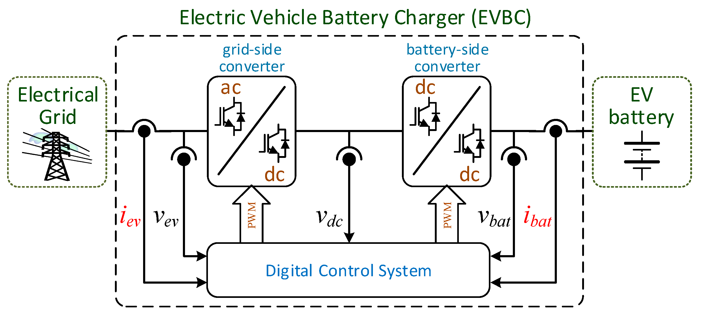
The principle of operation of an on-board and an off-board EVBC, also highlighting its internal constitution, is presented in this section. Internally, an EVBC is composed of power electronics converters and their control systems, responsible for controlling the EV battery charging and, in conjunction with the other elements of the EV, for establishing a communication with the energy management system of the smart grid or smart home with the concrete objective of defining set points of operation. Figure 1 shows the basic and classical structure of an EVBC, composed by two power converters (a grid-side one interfacing with the electrical grid and a battery-side one interfacing with the EV battery) and by the digital control system common to both power converters. Since the control is done with a closed-loop algorithm, this figure also shows the main control variables that are necessary to acquire, as well as the output control signals for the semiconductors of the power converters.
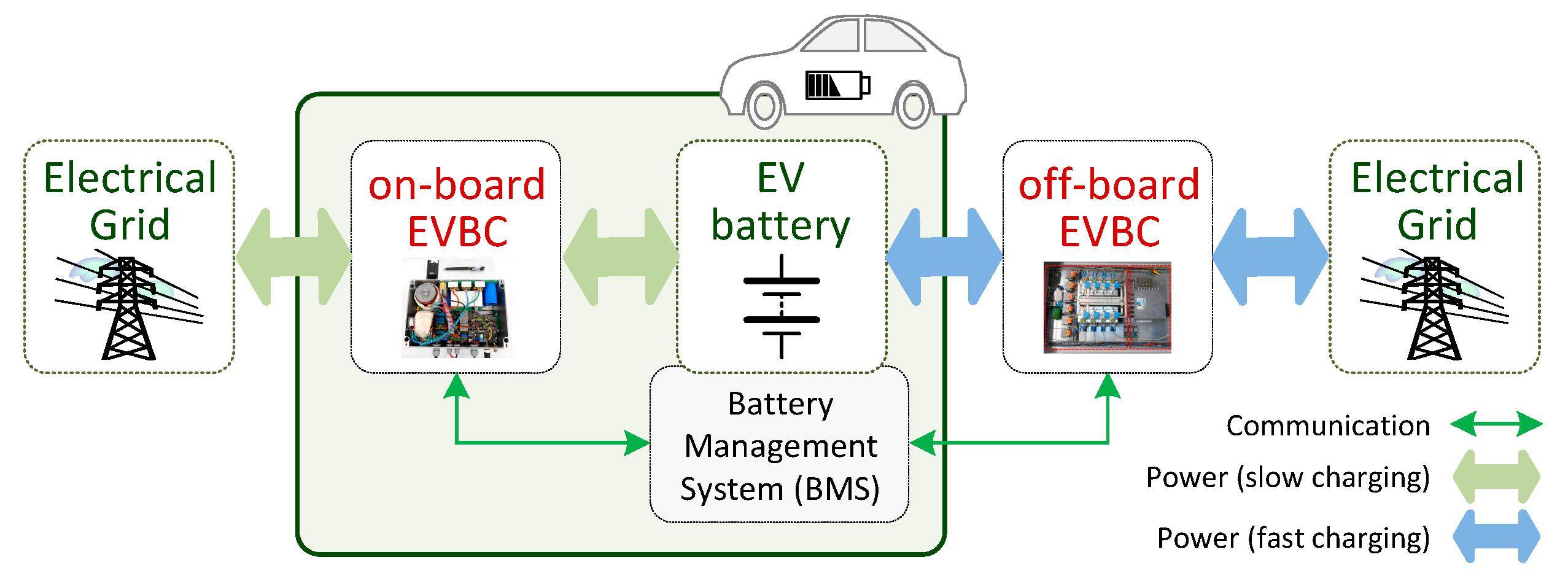
This is the customary organization of an EVBC, however, it can be classified according to its arrangement with respect to the EV, i.e., on-board and off-board. An EVBC is classified as on-board when the power electronics required to charge the EV battery are inside the EV, i.e., the converter responsible for controlling the stages of battery charging is inside the EV (usually more than a single controlled stage of voltage and current). Figure 2 shows the interface of an EV with the power grid through an on-board EVBC and an off-board EVBC. The power converters of the on-board EVBC are responsible for the bidirectional power flow between the electrical grid and the EV battery. For the grid-side, the ac-dc converter can be controlled by current or voltage according to the operating mode and for the battery-side, the dc-dc converter can also be controlled by current or voltage according to the intended operating mode for the charging system (c.f. Section 3). As shown in the figure, the operating mode is defined by specific control algorithms, whose management is in accordance with the information from the battery management system (BMS), i.e., the BMS establishes the limits of voltage and current during the charging or discharging processes. On the other hand, an EVBC is classified as off-board when the power electronics required to charge the EV battery are outside the EV, i.e., the converters that are responsible for controlling the battery charging stages (usually a single current controlled stage) are outside the EV. An off-board EVBC is composed by a grid-side converter and by a battery-side converter, both allowing bidirectional power flow between the electrical grid (with current control) and the EV battery (also with current control), i.e., in both cases, it is similar to the operation presented previously for the on-board EVBC. Moreover, for the off-board structure, the control of the operating mode is also defined in accordance with the information provided by the BMS.
2.2. Wireless Charging Systems
In the previous section the on-board and off-board EV battery chargers (EVBCs) were introduced. Due to weight and volume restrictions from the EV perspective, normally on-board EVBCs are designed for far lower power ratings than off-board EVBCs. However, it is important to distinguish that, from the electrical grid point of view, in both cases, the EVBCs can have a galvanic isolation or not, either for safety reasons or for convenience, in order to reduce operating voltage levels (i.e., the levels between the grid and the EV battery). In addition to the galvanic isolation that can be implemented for on-board and off-board systems, EVBCs can also be classified as wired or wireless, depending on whether there is a physical link between the electrical grid and the EVBC. Usually, in a wireless system, a part of the power electronics converter is outside the EV (off-board) and the other part is inside the EV (on-board).
Wireless charging systems are becoming popular for different appliances and for EVs; therefore, the main automakers are also developing realistic solutions for their EVs, including a significant range of charging levels. These wireless charging systems, which have been explored by different companies over the last decades, are also seen as a key opportunity to disseminate the electric mobility market, since it is a new exciting experience for the user. Complete overviews about wireless charging technologies for applications in electric mobility are presented in [40,41,42,43]. A basic wireless charging system consists in a fixed ground pad that stays below the EV during the charging and a receiving system that stays embedded in the inferior part of the EV. In addition to the need to increase the efficiency of the power transfer between the ground pad and the EV, which will involve the use of innovative technologies of power converters, the full adoption of wireless charging systems will rely on industry standards, universal communication with any EV and the charging pad, and safety issues for human beings and animals.
2.3. EV in Smart Grids: Coordination and Power Quality
As demonstrated in [44] and [45], the EV dissemination signifies a vast contribution for electrical grids, both in terms of future trends and control coordinating strategies. For example, the collaborative operation between EVs and RES is introduced in [46], and the contextualization with smart homes and microgrids is presented in [47] and [48]. Taking into account the EV operation in G2V and V2G modes framed in smart grids, several key points can be addressed. For instance, the impact on distribution systems is analyzed in [49], the coordination with RES scenarios is explored in [50], the contribution to reducing operating costs and to regulating the grid voltage frequency is explored in [51], and the dynamic operation as a function of other appliances is investigated in [52]. Besides the G2V and V2G modes, the EV can also contribute to improving power quality issues. For instance, the EVBC operation as an active filter is introduced in [53] and [54], and the EVBC contribution for compensating reactive power in the electrical grid is investigated in [55] and [56]. In the context of power quality, an overview about power quality in smart grids is established in [57], a collaborative support between RES and EVs for enhancing power grid support is analyzed in [58], the key aspects of the EVs integration into smart grids are discussed in [59], and innovative operations for the EVs connected into power grids toward mitigating issues of power quality are proposed in [60].
3. Opportunities for Smart Grids
Section 2 introduced the different structures that can be considered for an EVBC. As the analysis of the structures in terms of power electronics is not the objective of this paper, but the challenges and opportunities of vehicle electrification in smart grids and smart homes, the particular details of the topologies of the converters, either hardware or software, are not presented in this section.
3.1. On-Board EV Battery Charger
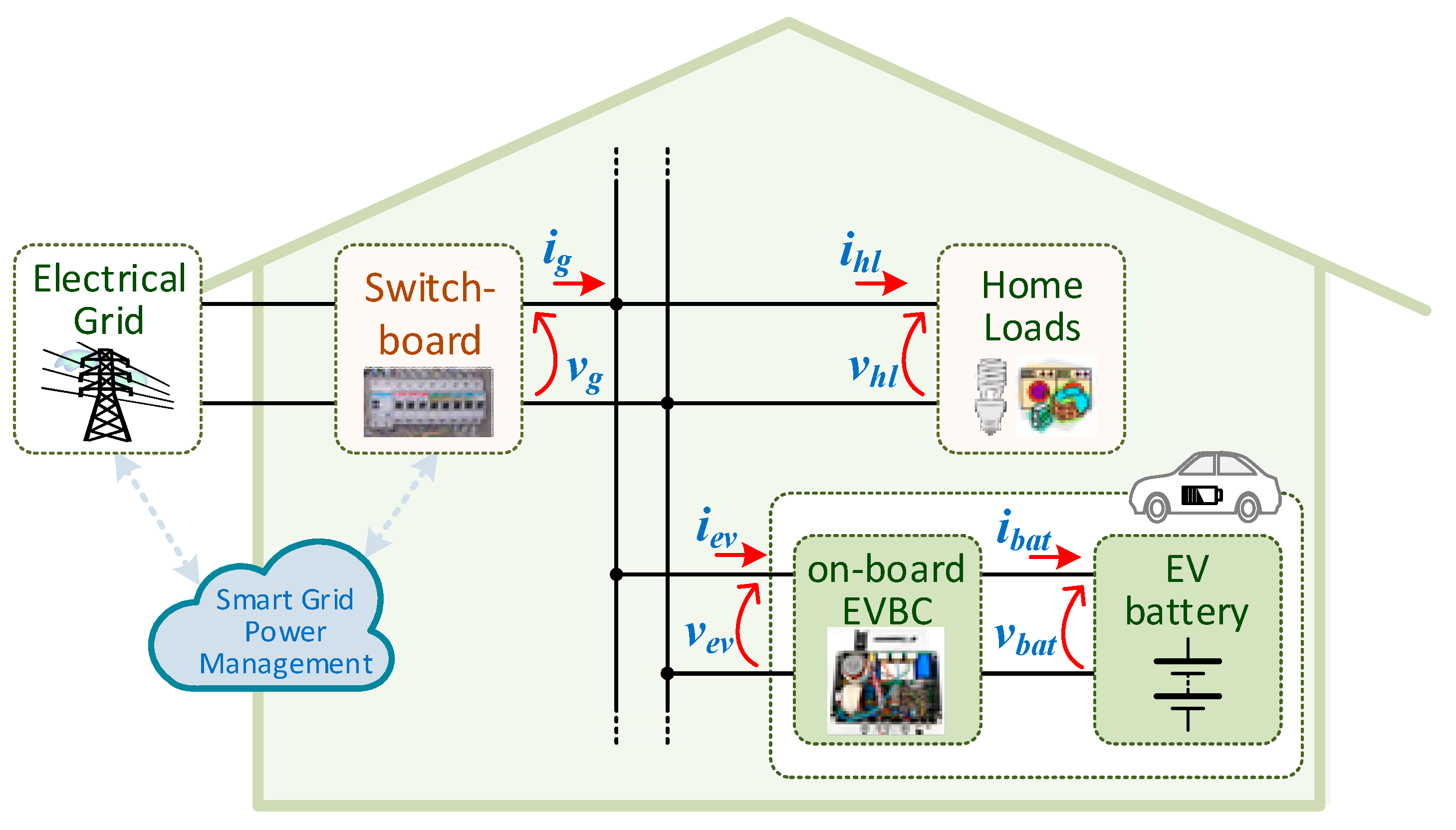
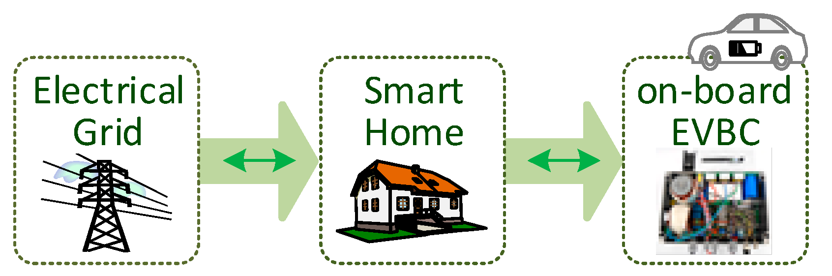
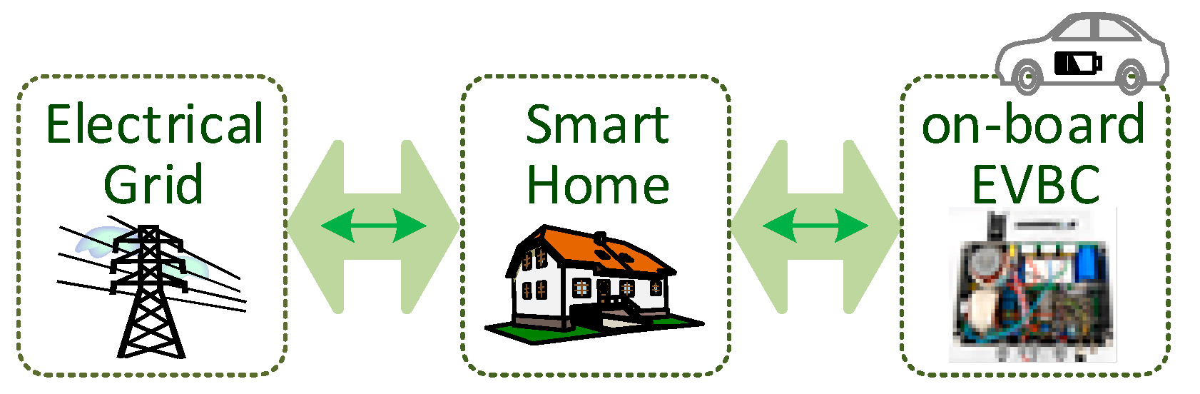
This section presents the main operation modes of an on-board EVBC, taking into account its limitations and the opportunities that they can offer for the operation in smart grids and smart homes, concretely, in terms of power controllability and new functionalities obtained for the installation where the EV is plugged-in. As an example case, Figure 3 illustrates the integration of an EV (including the on-board EVBC) into a smart home. As shown, the EV battery is charged through an on-board EVBC, which is connected to the electrical grid in parallel with the home loads, i.e., when present, the EV is treated as an additional home load. As illustrated, bidirectional communication is considered between the smart home and the electrical grid toward a smart grid perspective in terms of controllability.
3.1.1. Grid-to-Vehicle (G2V)
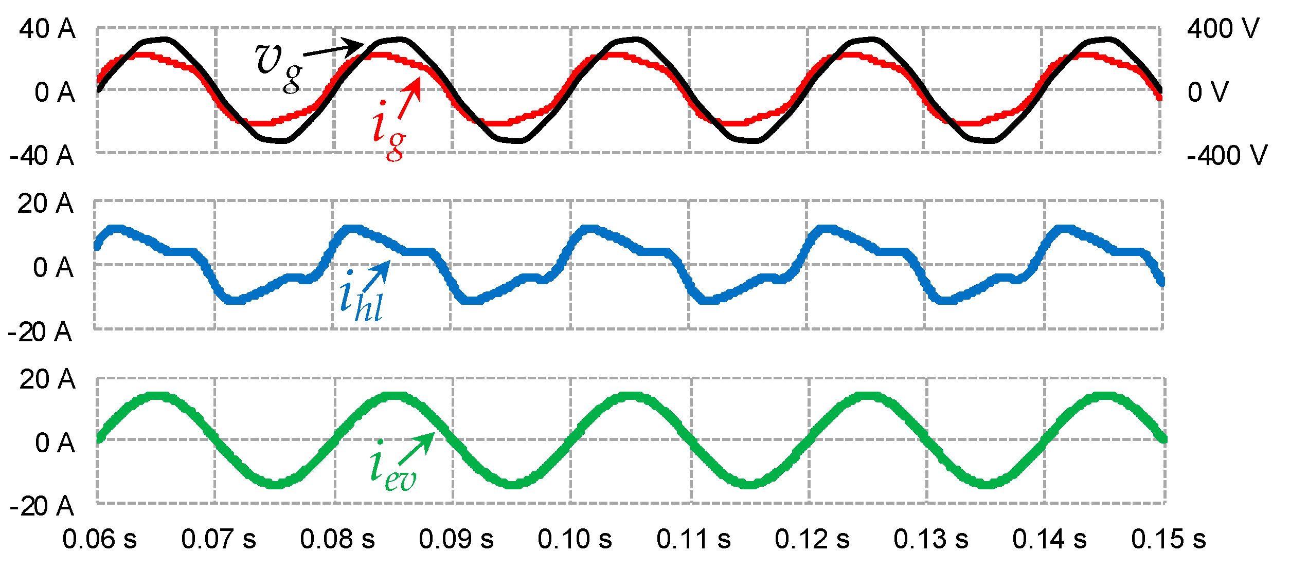
The G2V operation mode is exclusively concerned with the EV battery charging directly from the grid, and it is usually the only mode of operation available on EVs. As exemplified in Figure 4, the on-board EVBC is connected to the electrical grid through a smart home with unidirectional power flow and with bidirectional communication between the smart home, the electrical grid and the on-board EVBC. With this operation mode, the value of the EVBC grid-side current (iev) does not take into account the other loads connected in the same electrical installation (e.g., in the case of a home, the total current is limited by the main circuit breaker, which may be triggered if the limit is surpassed). The principle of operation representative of the G2V mode in a smart home is presented in Figure 5, where the grid voltage (vg), the grid current (ig), the home loads current (ihl) and the EVBC grid-side current (iev) are represented. In order to avoid deteriorating the power quality indices in the electrical grid, the EVBC current is sinusoidal and in phase with the grid voltage. As shown, realistic conditions are considered in terms of distorted grid voltage (vg) and home loads current (ihl).
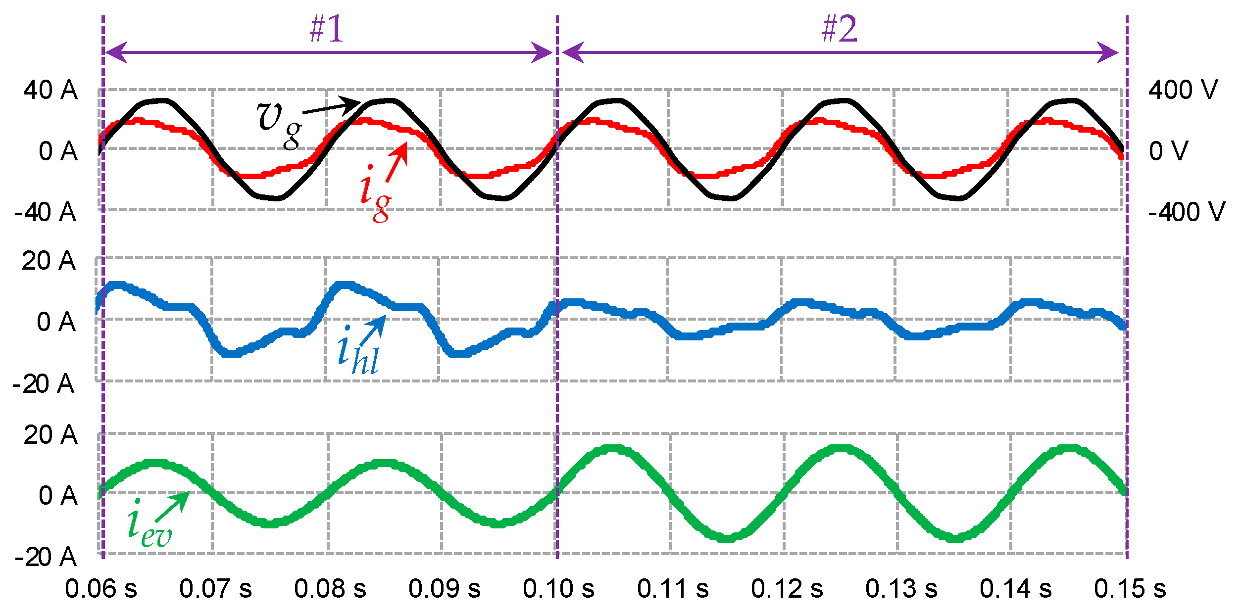
Similar to the (basic) G2V mode, the controlled G2V mode refers to the EV battery charging directly from the grid, but with adjustment of the operating power value according to the other connected loads [52]. Besides, with this operation mode, for example, the EVBC operating power may be adjusted according to the power injected by RES, aiming to balance the power production and consumption from the smart home perspective, and without harming the power quality on the grid-side (e.g., frequency and amplitude deviations on the grid voltage). In order to implement this operation mode, it is necessary to establish a communication between the EVBC and the grid (or the home energy management system, i.e., when considering the EV integration into a smart home). The principle of operation representative of the controlled G2V mode is exemplified in Figure 6. Similarly to the aforementioned G2V mode, the EVBC operates with a sinusoidal grid-side current; however, its amplitude is adjusted in real-time according to the other loads of the home. In the transition from case #1 to case #2, a home load was turned-off (the current consumption, ihl, decreases), so the EVBC increases its operating power (increases the current consumption, iev). Nevertheless, the maximum operating power of the EVBC, which is internally controlled, cannot be exceeded in any circumstance. Applying this control strategy to the EV battery charging, the maximum operating power of the smart home is never exceeded, maintaining the same value. This can be observable in the amplitude of the grid current (ig).
3.1.2. Vehicle-to-Grid (V2G)
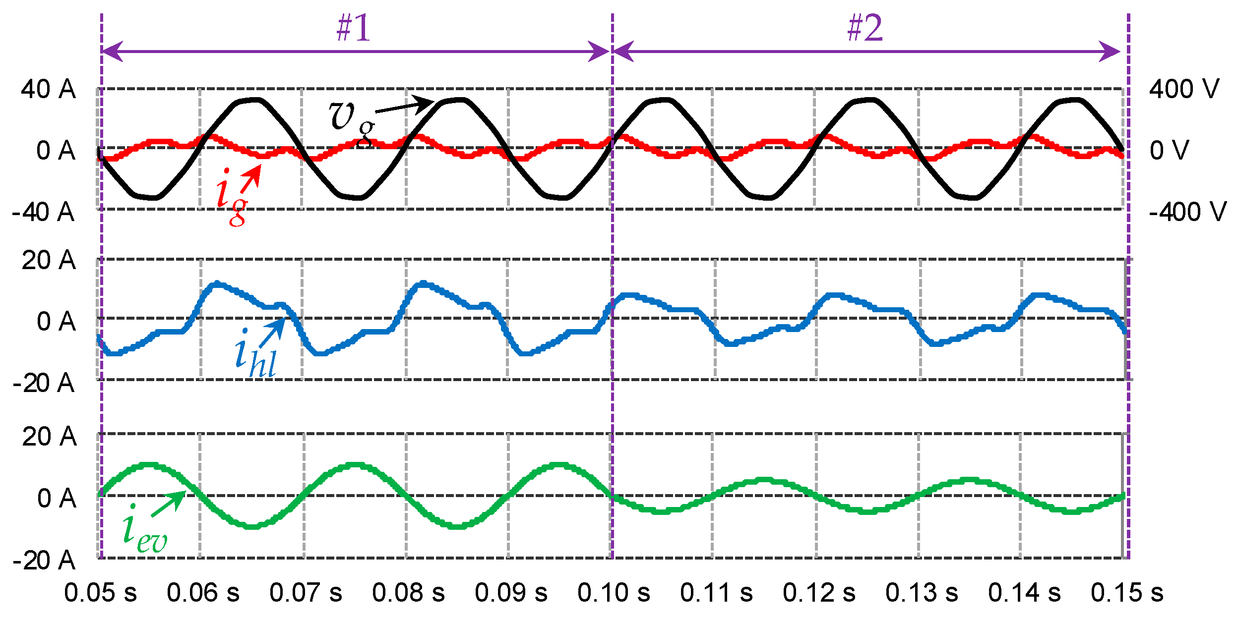
The V2G operation mode refers to the return of part of the energy stored in the EV battery to the grid conferring to the convenience of the grid management system and the EV user, representing a benefit for the electrical grid, because it allows using the EV as an ESS for supporting the grid stability. Contrary to the G2V, in this operation mode, the grid-side and the battery-side converters must be used in bidirectional mode, representing a perspective for the EVBCs of the future EVs. Moreover, this mode requires communication with a grid aggregator, in order to define in which schedules the EVBC operates in this mode, as well as the amount of power that is necessary to return to the grid. This operation mode, illustrated in Figure 7, is controlled according to the power injected into the grid, but it can also be controlled based on the loads connected in the same electrical installation. Figure 8 presents some results illustrating the V2G mode. Initially, in case #1, the EVBC is operating in V2G mode by injecting power into the grid without any control over the other loads, and then, in case #2, the EVBC injects power into the grid as a function of the other loads. In this specific case, a load was turned off; therefore, the power injected increases proportionally. As can be observed, in both cases, the EVBC grid-side current is in phase opposition with the voltage, meaning that power is injected into the grid.
3.1.3. Vehicle-to-Load (V2L)–Voltage Source
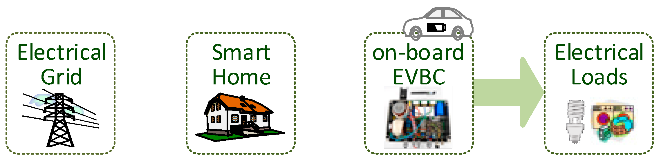
In the previously presented operation modes, the EVBC is controlled in order to absorb or inject power into the grid, where the grid-side converter operates with a current feedback control, i.e., the voltage is imposed by the grid and the EVBC defines the current waveform. In the operation mode as a voltage source, the EVBC operates independently from the grid, i.e., it can be used as a voltage source to power loads according to the user’s convenience. The principle of operation representative of the vehicle-to-load (V2L) mode, i.e., as a voltage source, is presented in Figure 9. This operation mode is useful, for example, in remote locations where a voltage source is only necessary for short periods. It may also be useful in campsites, or in extreme situations of catastrophic events where the grid may be unavailable. Thus, in this operation mode, the grid-side converter operates with a voltage feedback control, i.e., the voltage is imposed by the EVBC and the current waveform is defined by the linear or nonlinear loads connected to the EVBC. As operation mode uses the energy from the EV battery, the EV owner is responsible for the management of the battery state-of-charge, e.g., regarding the minimum acceptable state-of-charge for the next travel. Internally, the EV battery is protected by the BMS. Since this operation mode can be used in multiple locations and for various purposes (e.g., smart homes, remote locations, or in islanding mode), it represents a new contribution for the future smart grids. It is meaningful to note that Nissan already has a system entitle “LEAF-to-Home”, where the “EV Power Station” interfaces an EV and a house [61]. However, the key drawback of the Nissan system is that it can only be used where it is installed, i.e., it cannot be used generically with the EV in any place other than the home.
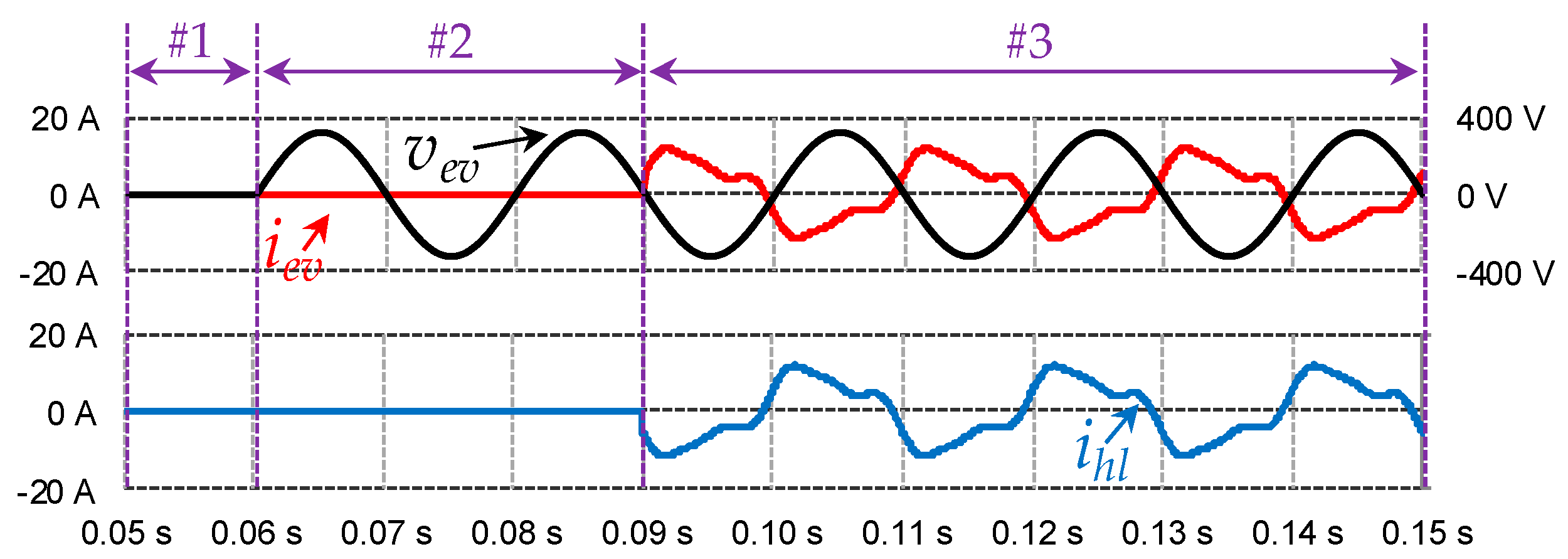
In Figure 10 the operating principle of this mode is presented, where ig represents the home current, iev represents the EVBC grid-side current, and ihl the loads current. As can be seen, when the EVBC is functioning as a voltage source, the EVBC current is the same as the load current, and the voltage applied to the loads is the voltage produced by the EVBC, whose value is equal to the nominal value of the grid voltage. This figure is divided into three distinct cases. In case #1, the EVBC is not operating in any mode. In case #2, the EVBC is not connected to the grid and starts to produce a sinusoidal voltage, but no load has yet been connected to the EVBC. In case #3, the EVBC is producing a sinusoidal voltage and a load is connected to the EVBC. In this case, since a nonlinear load was connected, it results in a consumed current with a high harmonic content.
3.1.4. Vehicle-to-Home (V2H)–Uninterruptible Power Supply
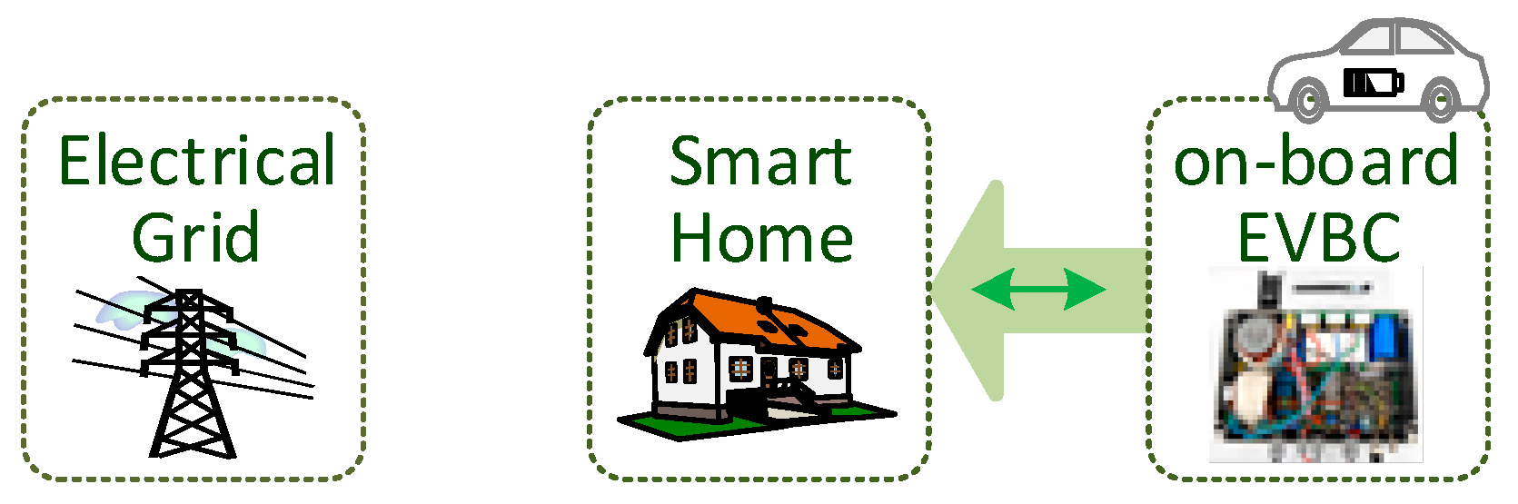
In addition to the operation mode presented earlier, the EVBC can also operate as a voltage source, but with the characteristics of an off-line uninterruptible power supply (UPS). This mode represents a new opportunity for smart homes because, in the event of a power failure, the EVBC can operate almost instantly as a voltage source for the smart home. In this operation mode, communication is required between the EVBC and the smart home, in order to identify a power outage and even to some selected priority loads. The principle of operation representative of the vehicle-to-home (V2H) mode as a UPS is presented in Figure 11, which clearly identifies that the EVBC operates in unidirectional mode and disconnected from the electrical grid.
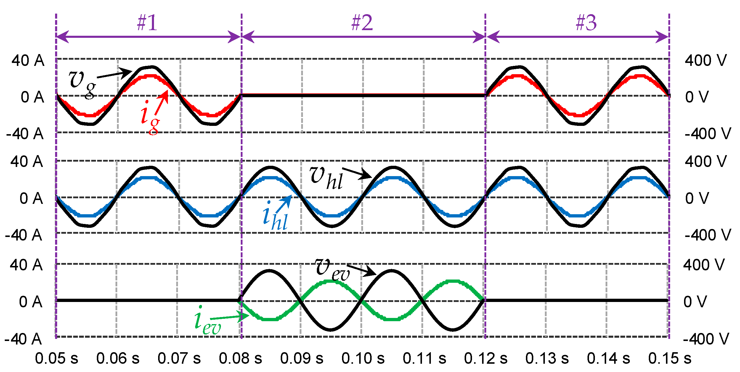
Like the previously presented operation mode, the grid-side converter of the EVBC operates with a voltage control feedback and the current is defined by the loads. However, unlike the previous mode, it is necessary to measure the grid voltage in order to detect when a voltage failure happens. Whenever this occurs, a control signal is sent to the general circuit breaker, to isolate the loads from the grid, and, almost instantaneously, the EVBC starts its operation as a voltage source. Later, when the grid voltage is restored, the EVBC recognizes this situation. Then, after some cycles of the grid voltage, it begins a synchronization with the phase of the voltage and, as soon as the control system is synchronized, it makes the transition to the normal mode, i.e., the loads are fed again by the grid. After this process, the EVBC may either go to an idle state or start another operation mode, such as G2V or V2G. Figure 12 illustrates the operating principle of this mode, showing the grid voltage (vg), the grid current (ig), the loads voltage (vhl), the loads current (ihl), the voltage produced by EVBC (vev), and the EVBC current (iev). This operation mode is divided into four cases. In case #1 the EVBC is connected to the grid to charge the batteries through the G2V operation mode (i.e., with a sinusoidal current and unitary power factor). In case #2, there is a fault in the grid voltage, detected by the EVBC, which starts operating in UPS mode, feeding the loads. In case #3, the grid voltage is restored and the EVBC stops operating in the UPS mode and the loads are fed back through the electrical grid again, as in case #1. As shown, even with a distorted grid voltage in cases #1 and #3, during the outage (case #2), the EVBC produces a sinusoidal voltage.
3.2. Off-Board EV Battery Charger
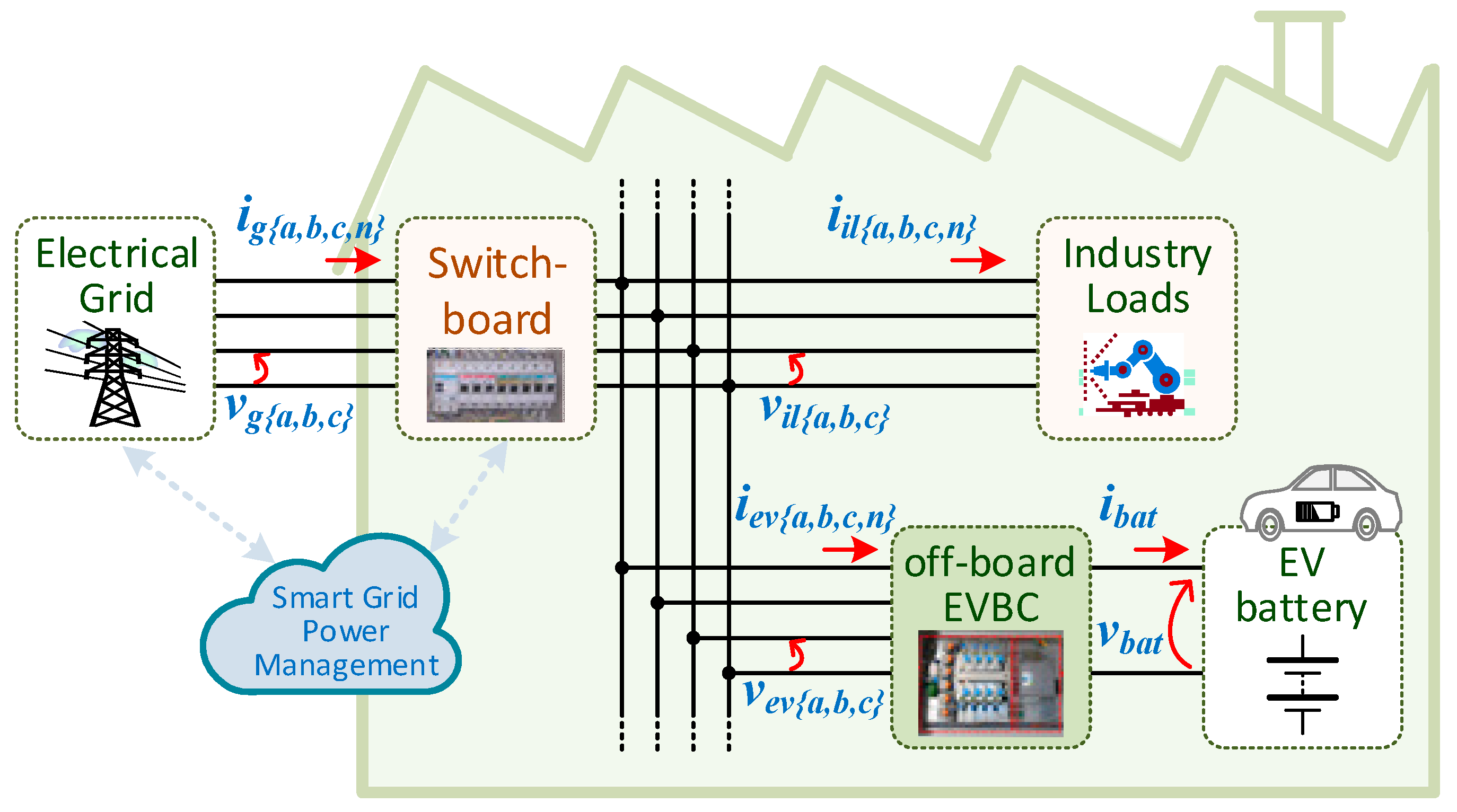
The main operation modes of an off-board EVBC are presented in this section, addressing the opportunities that they can offer for a contextualized operation with smart grids and smart homes, both in terms of controllability and new features that can be obtained for the installation where the EV is plugged-in. It is relevant to note that an off-board EVBC can be classified as slow, semi-fast, fast or ultra-fast; however, the modes of operation presented in this section are independent of this classification. Moreover, an off-board EVBC can be installed into the electrical grid through a single- or a three-phase interface. As an example case, Figure 13 illustrates the integration of an off-board EVBC into an industry. As shown, the EV battery is charged through the off-board EVBC, which is connected to the electrical grid in parallel with the home loads. Therefore, the off-board EVBC is continuously linked to the electrical grid independently of the EV presence. As illustrated, bidirectional communication is considered between the industry and the electrical grid towards a smart grid perspective in terms of controllability.
3.2.1. Grid-to-Vehicle and Vehicle-to-Grid
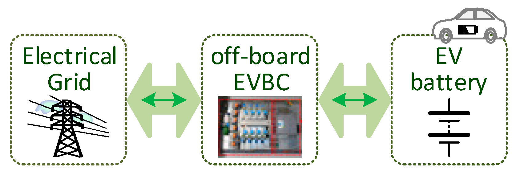
As with an on-board EVBC, an off-board EVBC also enables the G2V mode, regardless of the grid operation in terms of power management. Therefore, the central difference between an on-board and an off-board EVBC is the operating power, where, customarily, the off-board EVBC operates with a significantly higher power. In addition to the G2V operation mode, the V2G operation mode is also possible in an off-board EVBC, however, this mode is presented as a new opportunity for off-board EVBCs, since it is important to note that, nowadays, off-board EVBCs are unidirectional, but for operation in V2G mode they need to be bidirectional.
The principle of operation representative of an EVBC in G2V and V2G modes is presented in Figure 14, where it is clearly identified that the EVBC operates in a bidirectional mode in terms of active power and in terms of a communication with the electrical grid. During the charging of the EV battery using an off-board EVBC, the intention is to carry out the process as quickly as possible. However, as the EV is connected to an off-board EVBC only for brief periods, the EV can return a minor part of the stored energy (e.g., for a power management strategy). For example, if the EV is plugged-in for performing a fast charging of about 30 minutes operating with a power of 30 kW, but for 30 s, it returns a power of 10 kW back to the electrical grid, then the total time will be exceeded in just 1 minute and 40 s. This represents a small amount of power for the electrical grid, but considering an EV fleet with this functionality and an electrical grid with prediction and management algorithms, this operation mode is quite attractive for off-board EVBCs.
3.2.2. Power Quality Compensator
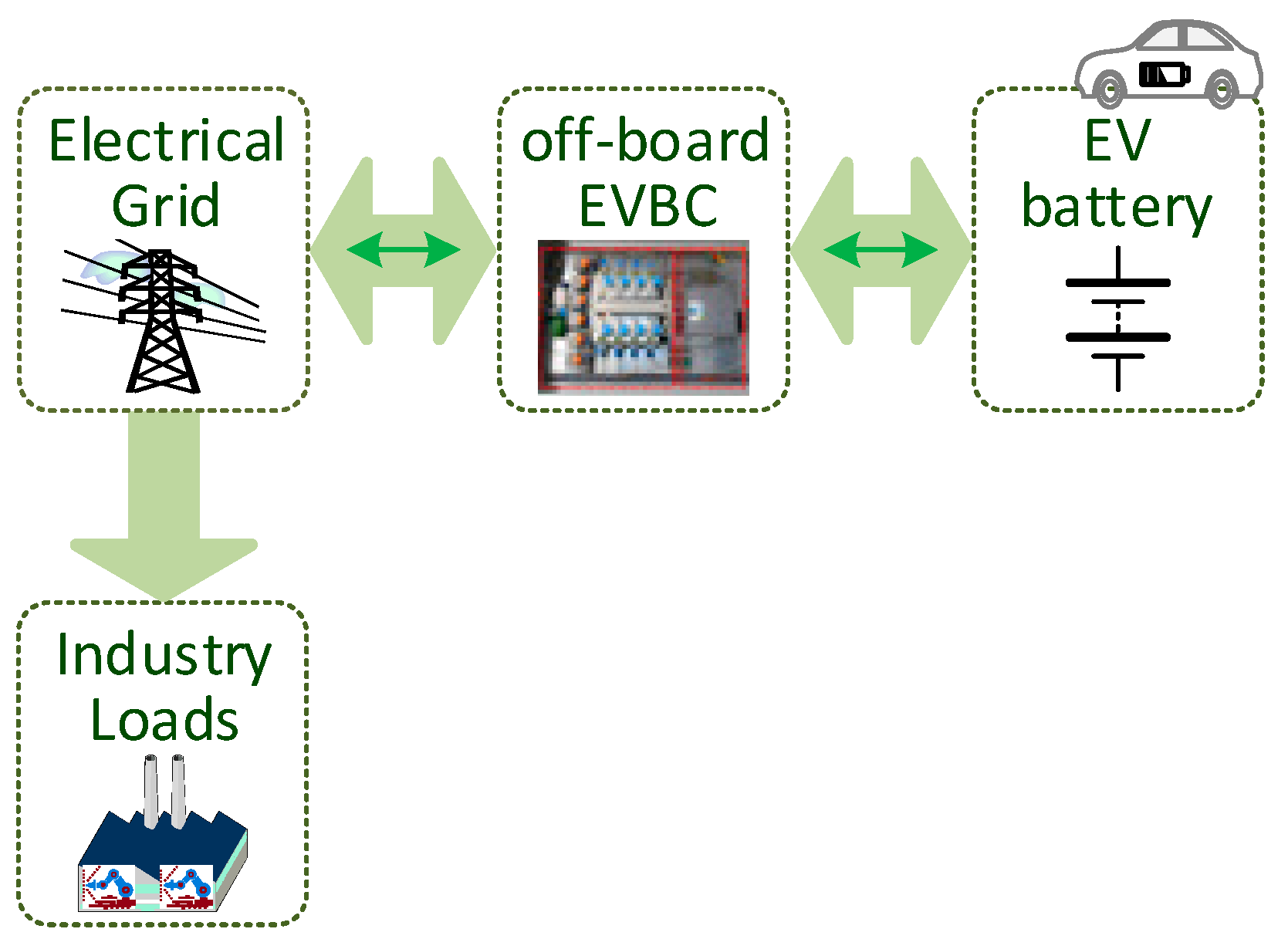
As noted earlier, off-board EVBCs are installed externally to the EV and are only used when it is necessary to charge the EV battery, a task that happens only for brief minutes. Thus, it is foreseeable that these systems may be out of operation during various periods along the day. In this sense, since an off-board EVBC is installed in a specific electrical installation, there is a new opportunity of operation for the off-board EVBC that is related to the possibility to compensate power quality problems for the electrical grid (caused by the nonlinear loads consuming distorted currents). This operation mode is even more significant knowing that it can be accomplished whether or not the EV is present, i.e., the power quality compensation can be performed at the same time that the batteries are being charged (G2V mode) without a detrimental effect on the EV battery or the EVBC operation. Moreover, it should be noted that this operation mode may also be used with the V2G mode. As the compensation is made to the grid-side, it is not necessary to transfer active power between the off-board EVBC and the electrical grid, which is a pertinent benefit to this operation mode. Moreover, no extra hardware is required for the operation in this mode, and it is only necessary to obtain the instantaneous current value of the installation.
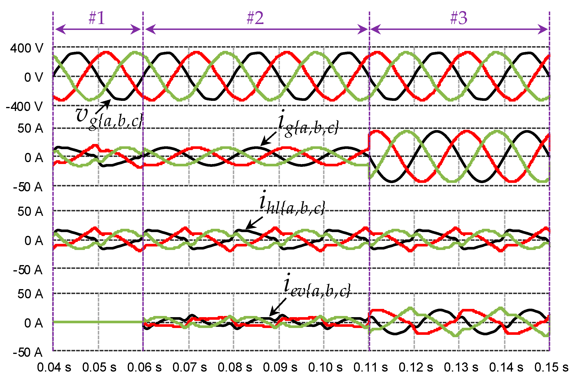
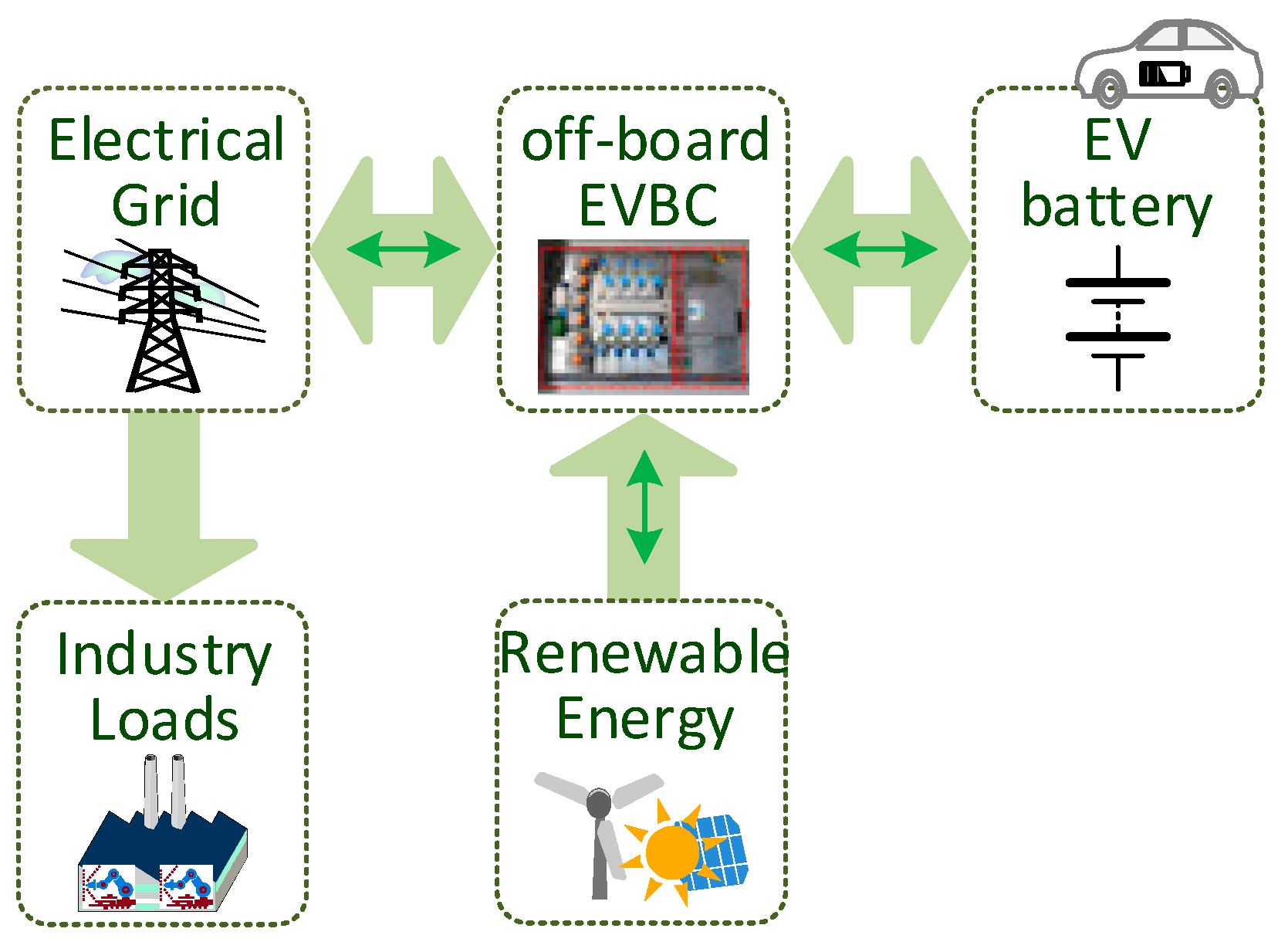
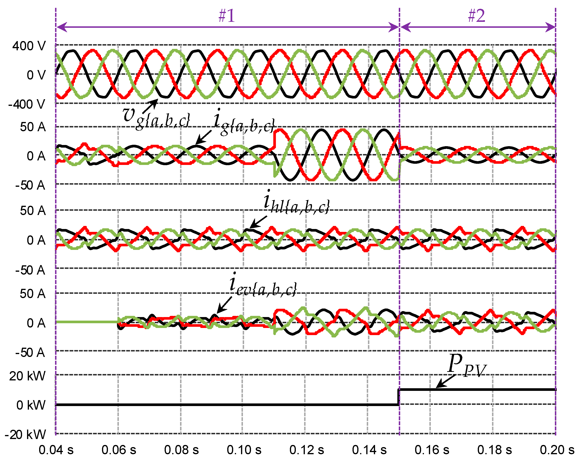
Figure 15 presents the framework of an off-board EVBC considering this new opportunity of operation, in which it is possible to compensate power quality problems related to power factor, current harmonics, and current imbalances. These power quality problems are caused by the loads presented in the industry, where the off-board EVBC is also installed. Given the offered benefit, this operation mode is especially suitable for EVBCs installed in industrial zones, where it is intended to minimize problems of power quality and to charge the EV battery as fast as possible. The operating principle of this mode is shown in Figure 16. Therefore, a three-phase installation is considered as a case example. In case #1, the off-board EVBC is connected to the grid without compensating power quality problems and without an EV in G2V or V2G modes. Therefore, the currents of the electrical installation are the consumed currents of the industry loads. In case #2, the process of power quality compensation (e.g., power factor and harmonics) is started without any EV plugged-in. In this case, as can be seen, on the grid-side, the power factor became unitary and the currents became sinusoidal and balanced. In case #3, in addition to the previous compensation, the off-board EVBC also starts the EV battery charging. As can be seen, the currents on the grid-side remain sinusoidal and balanced, only increasing its amplitude, corresponding to the active power required to charge the EV battery. Once again, it is imperative to remember that the operating active power of the EVBC is only used to charge the EV battery.
3.2.3. Unified Operation of Power Quality Compensator with Renewables
In the previous sections, new opportunities were presented for the EVBC operation in the context of smart grids. Knowing the influence that RES represent for the evolution and maturation of smart grids, as well as to minimize the impact that the EV battery charging represents in terms of the necessary power, their integration as close as possible to the off-board EVBC is of extreme relevance. For instance, solar photovoltaic panels, as an example of RES, can be used as a solar rooftop in EV charging stations or industries in order to accomplish with the opportunity mentioned in this section. In addition, since both off-board EVBCs and RES interface with the electrical grid using a grid-side converter, and each system has its own dc-link, a new opportunity is proposed in this section for smart grids, which consists of unifying both systems with only one interface with the electrical grid. Moreover, bearing in mind the opportunity identified in the previous section, the new opportunity identified a single interface with the electrical grid and the unification (through the dc-link) of the EVBC and the RES (which can be photovoltaic panels or wind turbines) is presented in Figure 17. Furthermore, with this unified strategy, it is conceivable to increase the efficiency compared to the customary solution in which two interfaces are used with the electrical grid, since the power coming from the RES can be directly used by the battery-side converter to charge the EV battery, without the need to use the grid-side converter.
Figure 18 presents the principle of operation of this mode, in part, supported by operations presented in the previous sections. In case #1, the off-board EVBC operates in the same way as in Figure 16, whereas in case #2 the off-board EVBC is used to inject power into the grid from the RES. As can be seen in this case, the effective values of the grid currents decrease due to the injected power from the RES, but the EV battery continues with the same charging power, meaning that the EV battery is being charged with energy from the RES.
3.2.4. Unified Operation of Power Quality Compensator, Renewables and Energy Storage Systems
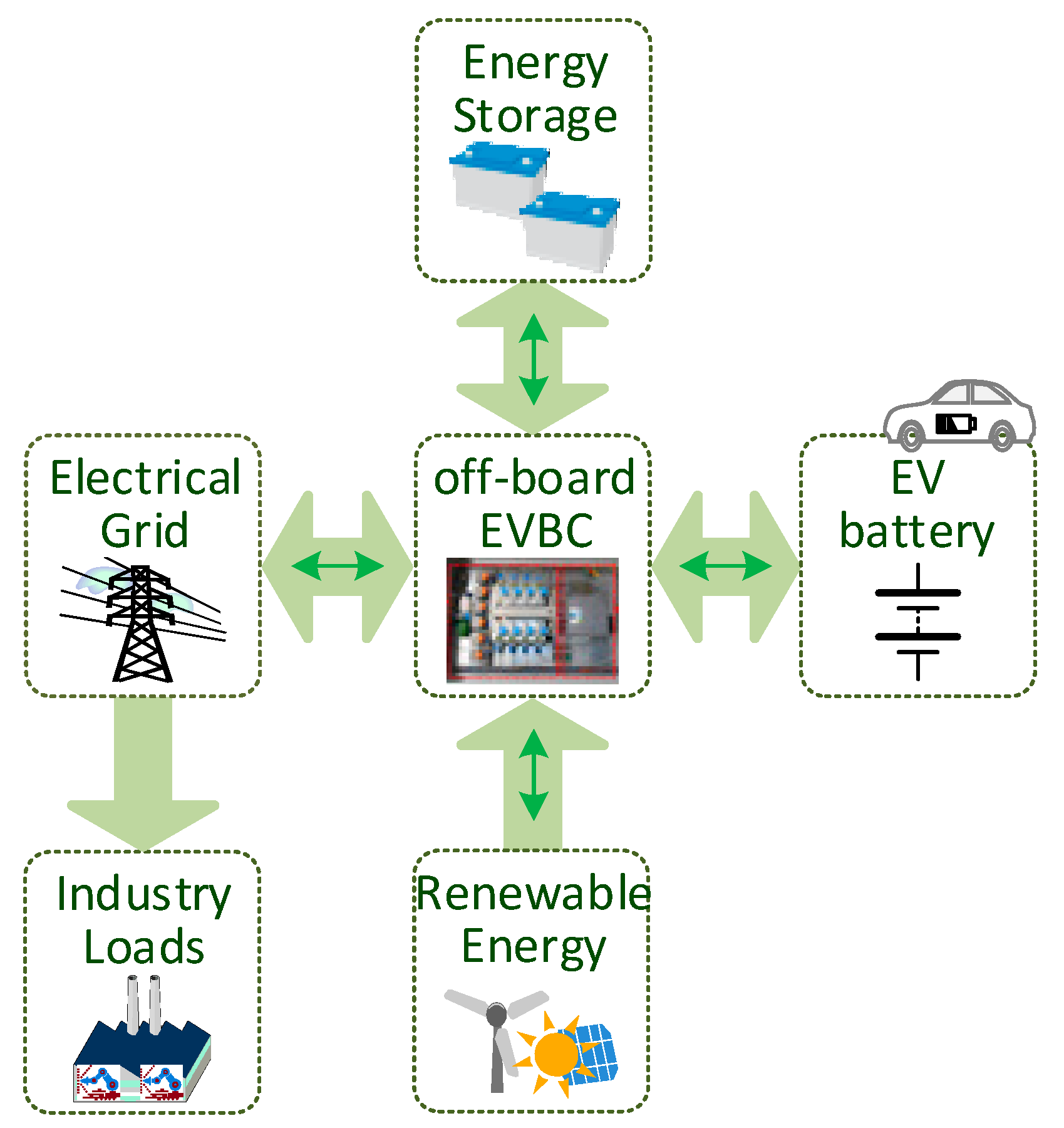
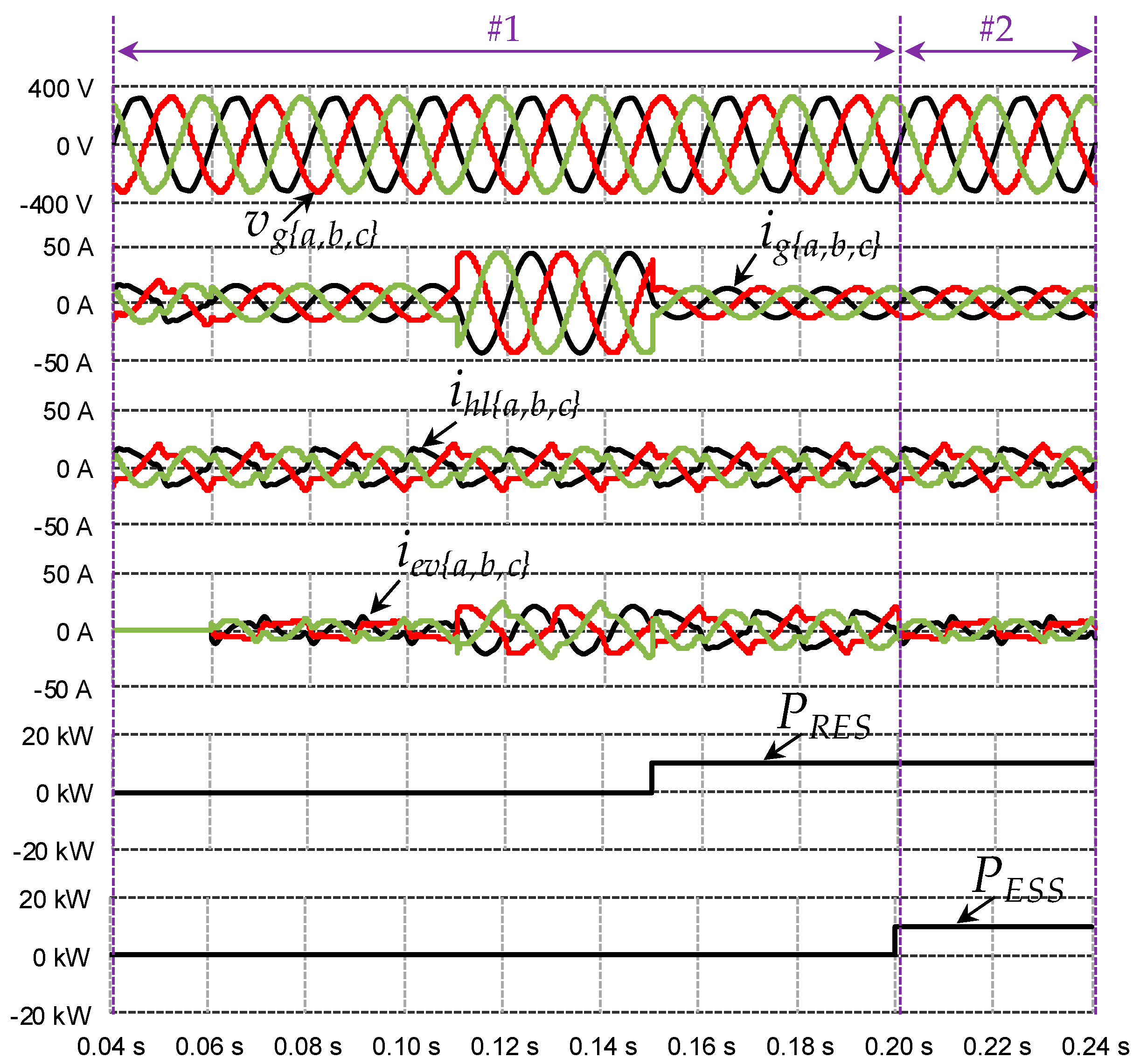
Following the opportunity presented in the previous section, providing the off-board EVBC with another interface on the dc-link, for an ESS, results in a new opportunity that includes the main aspects of smart grids in terms of power electronics. For instance, it should be noted that solar photovoltaic panels, as an example of RES, can be used as a solar rooftop in industries. In this way, it is possible to fit, in a single off-board EVBC equipment, the aspects of electric mobility, power quality, RES and ESS. Figure 19 shows this new opportunity, in which it is possible to recognize a single interface with the electrical grid and the unification (through the dc-link) of the converters for the EV battery charging, RES and ESS. Figure 20 shows the operation principle based on this proposal. In case #1, the off-board EVBC operates in the same way as shown in Figure 18. In case #2, after the EV charging process is completed, the energy produced by the RES is stored in the ESS. As shown in this case, the off-board EVBC compensates the currents of the industry loads and stores the power from the RES in the ESS at the same time.
4. Laboratory Prototypes
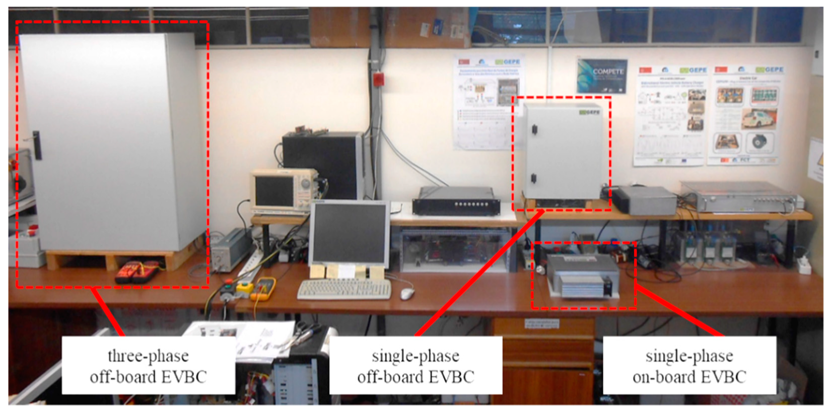
This section presents three examples of laboratory prototypes employing some of the operation modes referred to in the previous section. Figure 21 shows a photograph of a laboratory workbench where an on-board system and two off-board systems are presented. These prototypes were developed considering real-scale applications.
The on-board EVBC interfaces the electrical grid through a single-phase connection and allows operating in controlled G2V and V2G modes, as well as in voltage source mode or UPS mode. It is composed of two power stages, a grid-side converter and a battery-side converter, joined by a common dc-link.
One off-board EVBC interfaces with the electrical grid through a three-phase connection. It is constituted by two power converters (three-phase grid-side and battery-side) and allows the simultaneous and controlled G2V operation, as well as the compensation of power quality problems for the grid (e.g., current harmonics and reactive power), which is a feature that can be accomplished independently of the EV presence.
The other off-board EVBC interfaces the electrical grid through a single-phase connection. It is also constituted by two power stages, but with three accessible interface ports. A bidirectional ac-dc grid-side converter is employed to interface the electrical grid. In the dc-side, two separate interfaces are possible: A bidirectional dc-dc battery-side converter for the EV battery interface (empowering the G2V and V2G modes) and a unidirectional dc-dc converter for the interface of a RES (in this case a set of photovoltaic panels were considered). The simultaneous compensation of power quality problems is also possible.
It is fundamental to note that it is not the objective of this paper, and in particular this section, to establish a careful description about the internal constitution of the converters presented in the various prototypes, as well as the various control algorithms. In counterpart, the evident objective is to present a set of EVBCs that are capable of operating in several modes, representing new challenges and opportunities for smart grids and smart homes.
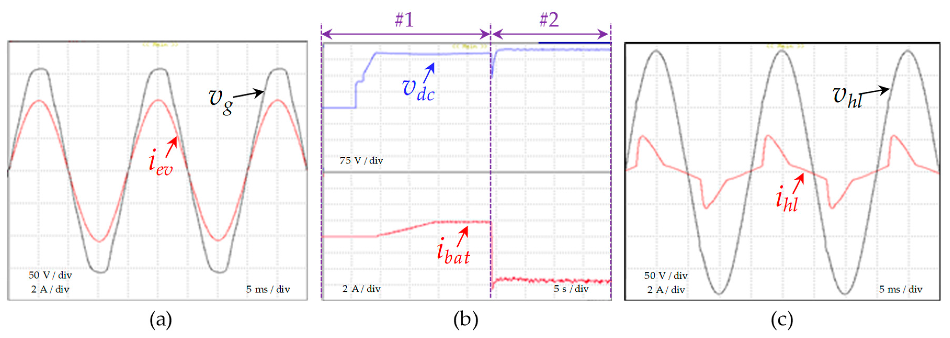
Figure 22 presents some experimental results for the single-phase on-board EVBC shown in Figure 21. Figure 22a presents the grid-side current (iev) and voltage (vg), evidencing a sinusoidal current and a distorted voltage, meaning that the control algorithm employs a phase-locked loop, contributing to reduce power quality problems. A unitary power factor, voltage, and current in phase, is also verified. Figure 22b shows an experimental result with the on-board EVBC operating as a UPS. This result is divided into two distinctive circumstances: In case #1, the EVBC operates in G2V mode and in case #2 in UPS mode. At the beginning of case #2, a power outage occurs in the electrical grid, interrupting the G2V mode for transition to the UPS mode. This transition was performed automatically, and the power outage was detected by measuring the root mean square (rms) grid voltage (vg). As shown, the battery-side current (ibat) is positive during case #1 (meaning the EV battery charging) and negative during case #2 (meaning the EV battery is discharging for the UPS operation). The dc-link voltage (vdc) is always positive, controlled by the grid-side converter during case #1 and controlled by the battery-side during case #2. As shown, a sudden variation occurs in the dc-link voltage aiming to compensate as fast as possible the power outage, i.e., the transition for the UPS mode. Lastly, Figure 22c shows the on-board EVBC operation as a UPS. As can be observed, the voltage produced by the on-board EVBC (vhl) is sinusoidal even when it supplies a nonlinear load, which is characterized by a high-distorted current consumption (ihl).
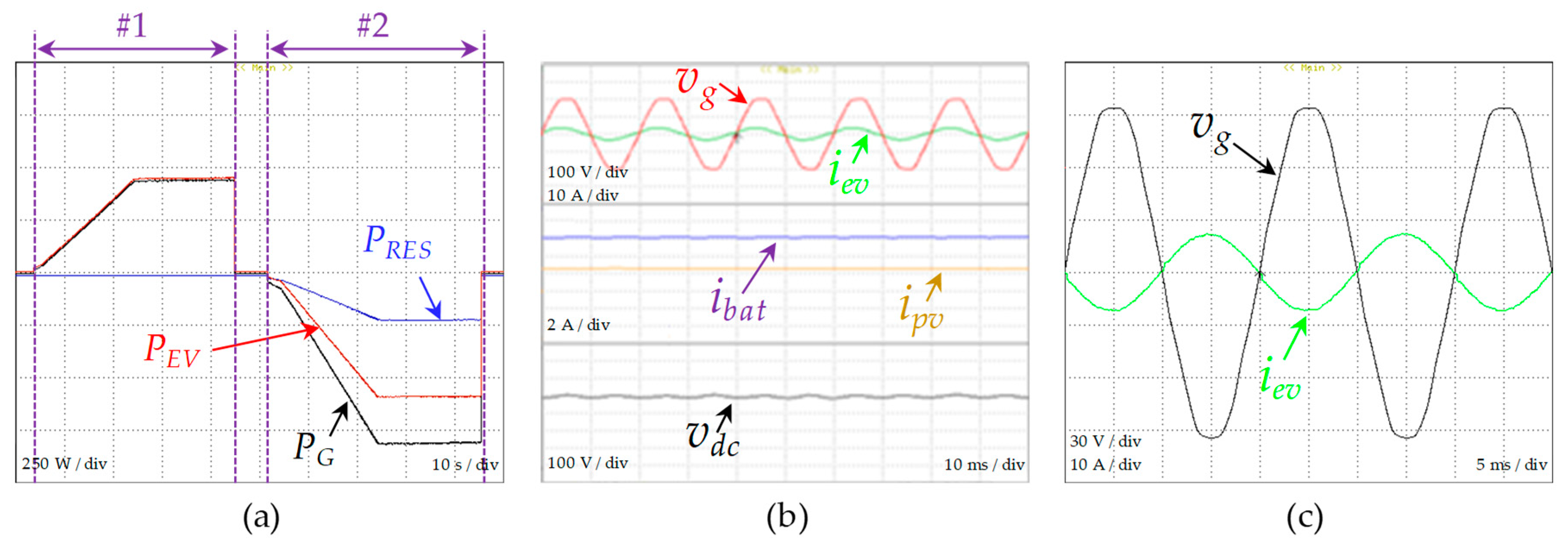
Figure 23 presents some experimental results for the single-phase off-board EVBC. Figure 23a shows the power in the three interfaces of the single-phase off-board EVBC, namely: The electrical grid interface (PG); the RES interface, in this case, photovoltaic panels (PRES); and the EV battery interface (PEV). This experimental result is divided into two distinct cases. During the case #1, the EV battery is charged from the grid and the RES is not producing energy, meaning that the grid-side power (PG) is equal to the battery-side power (PEV) and the RES power (PRES) is zero. In this case, the single-phase off-board EVBC operates in G2V mode. As can be seen, the operating power is increased up to its nominal value aiming to avoid sudden variations for the grid and for the EV battery. During case #2, the single-phase off-board EVBC operates in V2G mode and the PV panels start their production, meaning that the power injected into the electrical grid (PG) is the sum of the power from the EV battery (PEV) and the power from the RES (PRES). Figure 23b shows the grid-side current (iev) and voltage (vg) of the off-board EVBC, as well as the dc-link voltage (vdc), the EV battery-side current (ibat), and the RES (photovoltaic panels) current (ipv). In this mode (G2V), the grid-side current has a sinusoidal waveform, it is in phase with the voltage, and the dc variables are controlled according to the operation of the single-phase off-board EVBC. Lastly, Figure 23c shows the grid-side current (iev) with a sinusoidal waveform, but in opposition with the voltage waveform (vg), signifying that the single-phase off-board EVBC is operating in V2G mode, i.e., it is injecting power into the grid.
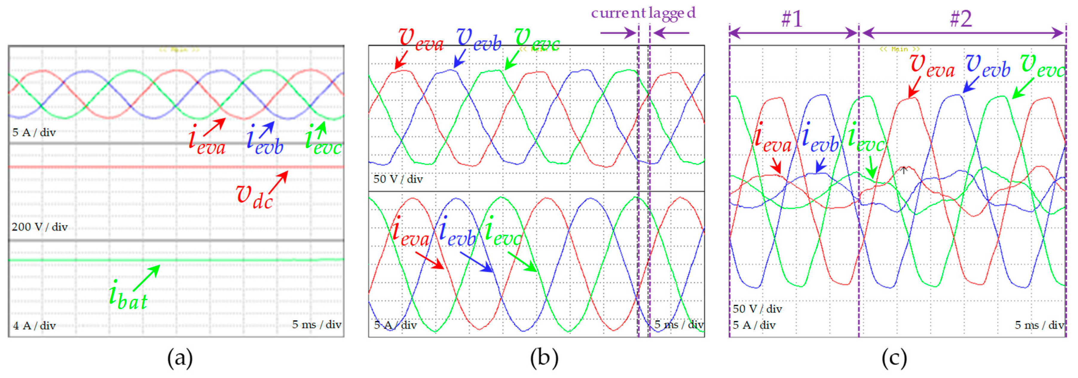
Figure 24 presents some experimental results of the three-phase off-board EVBC. Figure 24a shows the grid-side currents (iga, igb, igc) during the G2V mode, the dc-link voltage (vdc), and the EV battery current (ibat). As can be observed, the currents are balanced and sinusoidal waveforms are presented. The dc-side variables (vdc and ibat) are controlled in conformity. Figure 24b presents the grid-side voltages (vga, vgb, vgc) and the consuming lagged currents (iga, igb, igc) in order to produce reactive power for the grid, confirming the operation of the off-board EVBC for compensating power quality problems associated with reactive power caused by the connected loads. Lastly, Figure 24c presents the aforementioned variables, but in two distinct cases. In case #1, the off-board EVBC is operating in G2V mode (grid-side currents and voltages in phase) and, in case #2, it is operating with distorted grid-side currents to compensate the current harmonics presented in the installation (i.e., from the grid point of view, the electrical installation operates with sinusoidal currents), validating the operation of the off-board EVBC for compensating power quality problems related with harmonics.
5. Conclusions
Aiming towards an effective change of paradigm in the urban transportation sector, vehicle electrification already represents a reality, with a large predictable expansion and related opportunities ahead. However, new challenges are introduced in order to diminish undesirable effects that this revolution can cause to the electrical power grid. In this sense, this paper introduces a comprehensive discussion of new challenges and opportunities in terms of operation modes that can be addressed by on-board and off-board electric vehicle battery chargers (EVBCs) toward smart grids.
Throughout the paper, it has been demonstrated that on-board EVBCs can be used for other purposes than just grid-to-vehicle (G2V) and vehicle-to-grid (V2G) operation. On the other hand, as far as off-board EVBCs are concerned, it has been demonstrated that they can be unified with other features of smart grids, such as renewable energy sources (RES) and energy storage systems (ESS), and, at the same time, compensating power quality problems in the places where they are installed. In this sense, the different opportunities that on-board and off-board EVBCs represent for smart grids have been widely presented and discussed, evidencing the resultant advantages of new technologies toward a sustainable future. As a case example, an experimental validation employing laboratory prototypes of on-board and off-board EVBCs was presented, abstracting the topologies of the power converters.
Author Contributions
V.M., J.A.A., J.C.F. and J.L.A. contributed equally to the conceptualization and writing of the paper.
Funding
This work was supported by COMPETE: POCI-01-0145-FEDER-007043 and FCT—Fundação para a Ciência e Tecnologia within the Project Scope: UID/CEC/00319/2013. This work was financed by the ERDF —European Regional Development Fund, through the Operational Programme for Competitiveness and Internationalisation—COMPETE 2020 Programme, and by National Funds through the Portuguese funding agency, FCT—Fundação para a Ciência e a Tecnologia, within project SAICTPAC/0004/2015-POCI-01-0145-FEDER-016434. This work is part of the FCT project 0302836 NORTE-01-0145-FEDER-030283.
Conflicts of Interest
The authors declare no conflict of interest.
References
- Bose, B.K. Global Warming—Energy, Environmental Pollution, and the Impact of Power Electronics. IEEE Ind. Electron. Mag. 2010, 4, 6–17. [Google Scholar] [CrossRef]
- Bozchalui, M.C.; Cañizares, C.A.; Bhattacharya, K. Optimal Energy Management of Greenhouses in Smart Grids. IEEE Trans. Smart Grid 2015, 6, 827–835. [Google Scholar] [CrossRef]
- Amin, S.M.; Giacomoni, A.M. Giacomoni, Smart Grid—Safe, Secure, Self-Healing. IEEE Power Energy Mag. 2012, 10, 33–40. [Google Scholar] [CrossRef]
- Gungor, V.C.; Sahin, D.; Kocak, T.; Ergut, S.; Buccella, C.; Cecati, C.; Hancke, G.P. Smart Grid and Smart Homes—Key Players and Pilot Projects. IEEE Ind. Electron. Mag. 2012, 6, 18–34. [Google Scholar] [CrossRef]
- Moslehi, K.; Kumar, R. A Reliability Perspective of the Smart Grid. IEEE Trans. Smart Grid 2010, 1, 57–64. [Google Scholar] [CrossRef]
- Galus, M.D.; Vayá, M.G.; Krause, T.; Andersson, G. The Role of Electric Vehicles in Smart Grids. WIREs Energy Environ. 2013, 2, 384–400. [Google Scholar] [CrossRef]
- Li, D.; Jayaweera, S.K. Distributed Smart-Home Decision-Making in a Hierarchical Interactive Smart Grid Architecture. IEEE Trans. Parallel Distrib. Syst. 2015, 26, 75–84. [Google Scholar] [CrossRef]
- Hashmi, M.H.; Hänninen, S.; Mäki, K. Survey of Smart Grid Concepts, Architectures, and Technological Demonstrations Worldwide. In Proceedings of the IEEE PES Conference on Innovative Smart Grid Technologies Latin America, Medellin, Colombia, 19–21 October 2011; pp. 1–7. [Google Scholar]
- Yu, X.; Cecati, C.; Dillon, T.; Simoes, M.G. The New Frontier of Smart Grids: An Industrial Electronics Perspective. IEEE Ind. Electron. Mag. 2011, 5, 49–63. [Google Scholar] [CrossRef]
- Vojdani, A. Smart Integration: The Smart Grid Needs Infrastructure That is Dynamic and Flexible. IEEE Power Energy Mag. 2008, 6, 71–79. [Google Scholar] [CrossRef]
- Gungor, V.C.; Sahin, D.; Kocak, T.; Ergut, S.; Buccella, C.; Cecati, C.; Hancke, G.P. Smart Grid Technologies: Communication Technologies and Standards. IEEE Trans. Ind. Inform. 2011, 7, 529–539. [Google Scholar] [CrossRef] [Green Version]
- Liu, N.; Chen, J.; Zhu, L.; Zhang, J.; He, Y. A Key Management Scheme for Secure Communications of Advanced Metering Infrastructure in Smart Grid. IEEE Trans. Ind. Electron. 2013, 60, 4746–4756. [Google Scholar] [CrossRef]
- Meliopoulos, A.S.; Cokkinides, G.; Huang, R.; Farantatos, E.; Choi, S.; Lee, Y.; Yu, X. Smart Grid Technologies for Autonomous Operation and Control. IEEE Trans. Smart Grid 2011, 2, 1–10. [Google Scholar] [CrossRef]
- Yan, B.; Luh, P.B.; Warner, G.; Zhang, P. Operation and Design Optimization of Microgrids With Renewables. IEEE Trans. Autom. Sci. Eng. 2017, 14, 573–585. [Google Scholar] [CrossRef]
- Blaabjerg, F.; Guerrero, J.M. Smart Grid and Renewable Energy Systems. In Proceedings of the ICEMS International Conference on Electrical Machines and Systems, Beijing, China, 20–23 August 2011; pp. 1–10. [Google Scholar]
- Ackermann, T.; Carlini, E.M.; Ernst, B.; Groome, F.; Orths, A.; O’Sullivan, J.; de la Torre Rodriguez, M.; Silva, V. Integrating Variable Renewables in Europe: Current Status and Recent Extreme Events. IEEE Power Energy Mag. 2015, 13, 67–77. [Google Scholar] [CrossRef]
- Bragard, M.; Soltau, N.; Thomas, S.; De Doncker, R.W. The Balance of Renewable Sources and User Demands in Grids: Power Electronics for Modular Battery Energy Storage Systems. IEEE Trans. Power Electron. 2010, 25, 3049–3056. [Google Scholar] [CrossRef]
- Beaudin, M.; Zareipour, H.; Schellenberglabe, A.; Rosehart, W. Energy Storage for Mitigating the Variability of Renewable Electricity Sources: An Updated Review. Energy Sustain. Dev. 2010, 14, 302–314. [Google Scholar] [CrossRef]
- Hernandez, J.E.; Kreikebaum, F.; Divan, D. Flexible Electric Vehicle (EV) Charging to Meet Renewable Portfolio Standard (RPS) Mandates and Minimize Green House Gas Emissions. In Proceedings of the IEEE ECCE Energy Conversion Congress and Exposition, Atlanta, GA, USA, 12–16 September 2010; pp. 4270–4277. [Google Scholar]
- Alam, M.R.; Reaz, M.B.I.; Ali, M.A.M. A Review of Smart Homes—Past, Present, and Future. IEEE Trans. Syst. Man Cybern. C Appl. Rev. 2012, 42, 1190–1203. [Google Scholar] [CrossRef]
- Erickson, L.E.; Robinson, J.; Brase, G.; Cutsor, J. Solar Powered Charging Infrastructure for Electric Vehicles: A Sustainable Development, 1st ed.; CRC Press: Boca Raton, FL, USA, 2017. [Google Scholar]
- Raghavan, S.S.; Khaligh, A. Electrification Potential Factor: Energy-Based Value Proposition Analysis of Plug-In Hybrid Electric Vehicles. IEEE Trans. Veh. Technol. 2012, 61, 1052–1059. [Google Scholar] [CrossRef]
- Saber, A.Y.; Venayagamoorthy, G.K. Plug-in Vehicles and Renewable Energy Sources for Cost and Emission Reductions. IEEE Trans. Ind. Electron. 2011, 58, 1229–1238. [Google Scholar] [CrossRef]
- Martínezij, I.J.; Garcia-Villalobos, J.; Zamora, I.; Eguia, P. Energy Management of Micro Renewable Energy Source and Electric Vehicles at Home Level. J. Mod. Power Syst. Clean Energy 2017, 5, 979–990. [Google Scholar]
- Lopes, J.P.; Almeida, P.M.; Silva, A.M.; Soares, F.J. Smart Charging Strategies for Electric Vehicles: Enhancing Grid Performance and Maximizing the Use of Variable Renewable Energy Resources. In Proceedings of the EVS24 International Battery, Hybrid and Fuel Cell Electric Vehicle Symposium, Stavanger, Norway, 13–16 May 2009; pp. 1–11. [Google Scholar]
- Saber, A.Y.; Venayagamoorthy, G.K. Resource Scheduling Under Uncertainty in a Smart Grid with Renewables and Plug-in Vehicles. IEEE Syst. J. 2012, 6, 103–109. [Google Scholar] [CrossRef]
- Robalino, D.M.; Kumar, G.; Uzoechi, L.O.; Chukwu, U.C.; Mahajan, S.M. Design of a Docking Station for Solar Charged Electric and Fuel Cell Vehicles. In Proceedings of the IEEE International Conference on Clean Electrical Power, Capri, Italy, 9–11 June 2009; pp. 655–660. [Google Scholar]
- Vithayasrichareon, P.; Mills, G.; MacGill, I.F. Impact of Electric Vehicles and Solar PV on Future Generation Portfolio Investment. IEEE Trans. Sustain. Energy 2015, 6, 899–908. [Google Scholar] [CrossRef]
- Tushar, W.; Yuen, C.; Huang, S.; Smith, D.B.; Poor, H.V. Vincent Poor, Cost Minimization of Charging Stations With Photovoltaics: An Approach with EV Classification. IEEE Trans. Intell. Transp. Syst. 2016, 17, 156–169. [Google Scholar] [CrossRef]
- Monteiro, V.; Pinto, J.G.; Afonso, J.L. Experimental Validation of a Three-Port Integrated Topology to Interface Electric Vehicles and Renewables with the Electrical Grid. IEEE Trans. Ind. Inform. 2018, 14, 2364–2374. [Google Scholar] [CrossRef]
- Pedrasa, M.A.; Spooner, T.D.; MacGill, I.F. Coordinated Scheduling of Residential Distributed Energy Resources to Optimize Smart Home Energy Services. IEEE Trans. Smart Grid 2010, 1, 134–143. [Google Scholar] [CrossRef]
- Tsui, K.M.; Chan, S.C. Demand Response Optimization for Smart Home Scheduling Under Real-Time Pricing. IEEE Trans. Smart Grid 2012, 3, 1812–1821. [Google Scholar] [CrossRef]
- Monteiro, V.D.; Pinto, J.G.; Exposto, B.F.; Ferreira, J.C.; Afonso, J.L. Smart Charging Management for Electric Vehicle Battery Chargers. In Proceedings of the IEEE VPPC Vehicle Power and Propulsion Conference, Coimbra, Portugal, 27–30 October 2014; pp. 1–5. [Google Scholar]
- Zhang, T.; Chen, W.; Han, Z.; Cao, Z. Charging Scheduling of Electric VehiclesWith Local Renewable Energy Under Uncertain Electric Vehicle Arrival and Grid Power Price. IEEE Trans. Veh. Technol. 2014, 63, 2600–2612. [Google Scholar] [CrossRef]
- Tushar, M.H.; Zeineddine, A.W.; Assi, C. Demand-Side Management by Regulating Charging and Discharging of the EV, ESS, and Utilizing Renewable Energy. IEEE Trans. Ind. Inform. 2018, 14, 117–126. [Google Scholar] [CrossRef]
- Boulanger, A.G.; Chu, A.C.; Maxx, S.; Waltz, D.L. Vehicle Electrification: Status and Issues. Proc. IEEE 2011, 99, 1116–1138. [Google Scholar] [CrossRef] [Green Version]
- Fan, Z.; Oviedo, R.M.; Gormus, S.; Kulkarni, P. The Reign of EVs? An Economic Analysis from Consumer’s Perspective. IEEE Electrif. Mag. 2014, 2, 61–71. [Google Scholar] [CrossRef]
- Dyke, K.J.; Schofield, N.; Barnes, M. The Impact of Transport Electrification on Electrical Networks. IEEE Trans. Ind. Electron. 2010, 57, 3917–3926. [Google Scholar] [CrossRef]
- Su, W.; Eichi, H.; Zeng, W.; Chow, M.Y. A Survey on the Electrification of Transportation in a Smart Grid Environment. IEEE Trans. Ind. Electron. 2012, 8, 1–10. [Google Scholar] [CrossRef]
- Li, S.; Mi, C.C. Wireless Power Transfer for Electric Vehicle Applications. IEEE J. Emerg. Sel. Top. Power Electron. 2015, 3, 4–17. [Google Scholar]
- Musavi, F.; Edington, M.; Eberle, W. Wireless Power Transfer: A Survey of EV Battery Charging Technologies. In Proceedings of the IEEE ECCE Energy Conversion Congress and Exposition, Raleigh, NC, USA, 15–20 September 2012; pp. 1804–1810. [Google Scholar]
- Wang, S.; Dorrell, D. Review of Wireless Charging Coupler for Electric Vehicles. In Proceedings of the IEEE IECON Annual Conference of the Industrial Electronics Society, Vienna, Austria, 10–13 November 2013; pp. 7272–7277. [Google Scholar]
- Ching, T.W.; Wong, Y.S. Review of Wireless Charging Technologies for Electric Vehicles. In Proceedings of the IEEE PESA International Conference on Power Electronics Systems and Applications, Hong Kong, China, 11–13 December 2013; pp. 1–4. [Google Scholar]
- Salmasi, F.R. Control Strategies for Hybrid Electric Vehicles: Evolution, Classification, Comparison, and Future Trends. IEEE Trans. Veh. Technol. 2007, 56, 2393–2404. [Google Scholar] [CrossRef]
- Lopes, J.A.; Soares, F.J.; Almeida, P.M. Rocha Almeida, Integration of Electric Vehicles in the Electric Power Systems. Proc. IEEE 2011, 99, 168–183. [Google Scholar] [CrossRef]
- Lam, A.Y.; Leung, K.C.; Li, V.O. Capacity Estimation for Vehicle-to-Grid Frequency Regulation Services With Smart Charging Mechanism. IEEE Trans. Smart Grid 2016, 7, 156–166. [Google Scholar] [CrossRef]
- Zipperer, A.; Aloise-Young, P.A.; Suryanarayanan, S.; Roche, R.; Earle, L.; Christensen, D.; Bauleo, P.; Zimmerle, D. Electric Energy Management in the Smart Home: Perspectives on Enabling Technologies and Consumer Behavior. Proc. IEEE 2013, 101, 2397–2408. [Google Scholar] [CrossRef]
- Tushar, M.H.; Assi, C.; Maier, M.; Uddin, M.F. Smart Microgrids: Optimal Joint Scheduling for Electric Vehicles and Home Appliances. IEEE Trans. Smart Grid 2014, 5, 239–250. [Google Scholar] [CrossRef]
- Yilmaz, M.; Krein, P.T. Review of the Impact of Vehicle-to-Grid Technologies on Distribution Systems and Utility Interfaces. IEEE Trans. Power Electron. 2013, 28, 5673–5689. [Google Scholar] [CrossRef]
- Lund, H.; Kempton, W. Integration of renewable energy into the transport and electricity sectors through V2G. Energy Policy 2008, 36, 3578–3587. [Google Scholar] [CrossRef]
- Gao, S.; Chau, K.T.; Liu, C.; Wu, D.; Chan, C.C. Chan, Integrated Energy Management of Plug-in Electric Vehicles in Power Grid With Renewables. IEEE Trans. Veh. Technol. 2014, 63, 3019–3027. [Google Scholar] [CrossRef]
- Monteiro, V.; Carmo, J.P.; Pinto, J.G.; Afonso, J.L. A Flexible Infrastructure for Dynamic Power Control of Electric Vehicle Battery Chargers. IEEE Trans. Veh. Technol. 2016, 65, 4535–4547. [Google Scholar] [CrossRef] [Green Version]
- Rodrigues, M.C.; Souza, I.D.; Ferreira, A.A.; Barbosa, P.G.; Braga, H.A. Simultaneous Active Power Filter and G2V (or V2G) Operation of EV On-Board Power Electronics. In Proceedings of the IEEE IECON Industrial Electronics Conference, Vienna, Austria, 10–13 November 2013; pp. 4684–4689. [Google Scholar]
- Monteiro, V.; Pinto, J.G.; Afonso, J.L. Operation Modes for the Electric Vehicle in Smart Grids and Smart Homes: Present and Proposed Modes. IEEE Trans. Veh. Tech. 2016, 65, 1007–1020. [Google Scholar] [CrossRef] [Green Version]
- Sun, Y.; Liu, W.; Su, M.; Li, X.; Wang, H.; Yang, J. A Unified Modeling and Control of a Multi-Functional Current Source-Typed Converter for V2G Application. Electr. Power Syst. Res. 2014, 106, 12–20. [Google Scholar] [CrossRef]
- Buja, G.; Bertoluzzo, M.; Fontana, C. Reactive Power Compensation Capabilities of V2G-Enabled Electric Vehicles. IEEE Trans. Power Electon. 2017, 32, 9447–9459. [Google Scholar] [CrossRef]
- An, L.U.; Qianming, X.U.; Fujun, M.A.; Yandong, C.H. Overview of Power Quality Analysis and Control Technology for the Smart Grid. J. Mod. Power Syst. Clean Energy 2016, 4, 1–9. [Google Scholar]
- Traube, J.; Lu, F.; Maksimovic, D. Photovoltaic Power System with Integrated Electric Vehicle DC Charger and Enhanced Grid Support. In Proceedings of the EPE/PEMC International Power Electronics and Motion Control Conference, Novi Sad, Serbia, 4–6 September 2012; pp. 1–5. [Google Scholar]
- Masoum, A.S.; Deilami, S.; Moses, P.S.; Abu-Siada, A. Ahmed Abu-Siada, Impacts of Battery Charging Rates of Plug-in Electric Vehicle on Smart Grid Distribution Systems. In Proceedings of the IEEE ISGT Innovative Smart Grid Technologies Conference Europe, Gothenberg, Sweden, 11–13 October 2010; pp. 1–6. [Google Scholar]
- Boynuegri, A.R.; Uzunoglu, M.; Erdinc, O.; Gokalp, E. A new perspective in grid connection of electric vehicles: Different operating modes for elimination of energy quality problems. Appl. Energy 2014, 132, 435–451. [Google Scholar] [CrossRef]
- Green Car Congress. Nissan to launch the ‘LEAF to Home’ V2Hpower Supply System with Nichicon ‘EV Power Station’ in June. Available online: http://www.greencarcongress.com/2012/05/leafvsh-20120530.html (accessed on 30 May 2012).
Figure 1.
Structure of an electric vehicle battery charger (EVBC) composed of two power converters (a grid-side one interfacing the electrical grid and a battery-side one interfacing the EV battery) and the digital control system.
Figure 1.
Structure of an electric vehicle battery charger (EVBC) composed of two power converters (a grid-side one interfacing the electrical grid and a battery-side one interfacing the EV battery) and the digital control system.

Figure 2.
Interface of an EV with the power grid through an on-board EVBC and an off-board EVBC.

Figure 3.
Illustration of the integration of an on-board EVBC into a smart home.

Figure 4.
On-board EVBC: Grid-to-vehicle (G2V) operation mode.

Figure 5.
Principle of operation representative of the G2V mode.

Figure 6.
Principle of operation representative of the controlled G2V mode.

Figure 7.
On-board EVBC: vehicle-to-grid (V2G) operation mode.

Figure 8.
The principle of operation representative of the V2G mode.

Figure 9.
On-board EVBC: Vehicle-to-load (V2L) operation mode (as a voltage source).

Figure 10.
The principle of operation representative of the V2L mode (as a voltage source).

Figure 11.
On-board EVBC: Vehicle-to-home (V2H) operation mode (as an off-line uninterruptible power supply).
Figure 11.
On-board EVBC: Vehicle-to-home (V2H) operation mode (as an off-line uninterruptible power supply).

Figure 12.
The principle of operation representative of the V2H mode (as an off-line uninterruptible power supply).
Figure 12.
The principle of operation representative of the V2H mode (as an off-line uninterruptible power supply).

Figure 13.
Illustration of the integration of an off-board EVBC into an industry.

Figure 14.
Integration of an off-board EVBC into the electrical power grid for G2V and V2G operation modes.
Figure 14.
Integration of an off-board EVBC into the electrical power grid for G2V and V2G operation modes.

Figure 15.
Integration of an off-board EVBC into the electrical power grid for operation as a power quality compensator.
Figure 15.
Integration of an off-board EVBC into the electrical power grid for operation as a power quality compensator.

Figure 16.
The principle of operation representative of the off-board EVBC operation as a power quality compensator.
Figure 16.
The principle of operation representative of the off-board EVBC operation as a power quality compensator.

Figure 17.
Off-board EVBC: Unified operation as a power quality compensator with renewables.

Figure 18.
Principle of operation representative of the off-board EVBC: Unified operation as a power quality compensator with renewables.
Figure 18.
Principle of operation representative of the off-board EVBC: Unified operation as a power quality compensator with renewables.

Figure 19.
Off-board EVBC: Unified operation of power quality compensator, renewables and energy storage systems.
Figure 19.
Off-board EVBC: Unified operation of power quality compensator, renewables and energy storage systems.

Figure 20.
Principle of operation representative of the off-board EVBC: Unified operation of power quality compensator, renewables and energy storage systems.
Figure 20.
Principle of operation representative of the off-board EVBC: Unified operation of power quality compensator, renewables and energy storage systems.

Figure 21.
Photography of the laboratory workbench with the on-board and off-board EVBCs.

Figure 22.
Experimental results of the single-phase on-board EVBC: (a) During 50 ms in the grid-to-vehicle (G2V) operation mode-grid-side current (iev) and voltage (vg); (b) during 50 s in the operation as a UPS-dc-link voltage (vdc) and battery-side current (ibat); (c) During 50 ms in the operation as a UPS-produced voltage (vhl) and consumed current (ihl).

Figure 23.
Experimental results of the off-board EVBC considering the integration of renewables (photovoltaic panels): (a) During 100 s in the grid-to-vehicle (G2V) and vehicle-to-grid (V2G) operation modes with renewables—power in the grid side (PG), power in the EV side (PEV) and power in the RES side (PRES); (b) during 100 ms in the G2V mode-grid-side current (iev) and voltage (vg), dc-link voltage (vdc), EV battery current (ibat), and photovoltaic panels current (ipv); (c) during 50 ms in the V2G mode-grid-side current (iev) and voltage (vg).

Figure 24.
Experimental results of the off-board EVBC compensating power quality problems: (a) During 50 ms in the G2V mode-grid-side currents (ieva, ievb, ievc), dc-link voltage (vdc), and EV battery current (ibat); (b) during 50 ms compensating power quality problems related with power factor-grid-side currents (ieva, ievb, ievc) and voltages (vga, vgb, vgc); (c) during 50 ms compensating power quality problems related with current harmonics-grid-side currents (ieva, ievb, ievc) and voltages (vga, vgb, vgc).

© 2018 by the authors. Licensee MDPI, Basel, Switzerland. This article is an open access article distributed under the terms and conditions of the Creative Commons Attribution (CC BY) license (http://creativecommons.org/licenses/by/4.0/).
Share and Cite
MDPI and ACS Style
Monteiro, V.; Afonso, J.A.; Ferreira, J.C.; Afonso, J.L. Vehicle Electrification: New Challenges and Opportunities for Smart Grids. Energies 2019, 12, 118. https://0-doi-org.brum.beds.ac.uk/10.3390/en12010118
AMA Style
Monteiro V, Afonso JA, Ferreira JC, Afonso JL. Vehicle Electrification: New Challenges and Opportunities for Smart Grids. Energies. 2019; 12(1):118. https://0-doi-org.brum.beds.ac.uk/10.3390/en12010118
Chicago/Turabian StyleMonteiro, Vitor, Jose A. Afonso, Joao C. Ferreira, and Joao L. Afonso. 2019. "Vehicle Electrification: New Challenges and Opportunities for Smart Grids" Energies 12, no. 1: 118. https://0-doi-org.brum.beds.ac.uk/10.3390/en12010118
Note that from the first issue of 2016, this journal uses article numbers instead of page numbers. See further details here.