Feasibility Analysis of Bio-Methane Production in a Biogas Plant: A Case Study
by
 , , and
Andrea Baccioli
1 ,
,
Lorenzo Ferrari
1,2,* ,
,
Romain Guiller
3,
Oumayma Yousfi
3,
Francesco Vizza
2 and
Umberto Desideri
1
1
Department of Energy, Systems, Territory and Constructions Engineering, University of Pisa, Largo Lucio Lazzarino 1, 56122 Pisa, Italy
2
National Research Council of Italy CNR-ICCOM – Via Madonna del Piano 10, 50019 Sesto Fiorentino (FI), Italy
3
Department of Thermal and Energy Science, Polytech Nantes, University of Nantes, Rue Christian Pauc, 44300 Nantes, France
*
Author to whom correspondence should be addressed.
Energies 2019, 12(3), 473; https://0-doi-org.brum.beds.ac.uk/10.3390/en12030473
Submission received: 31 December 2018
/
Revised: 27 January 2019
/
Accepted: 29 January 2019
/
Published: 1 February 2019
(This article belongs to the Section A: Sustainable Energy)
Abstract
:A feasibility analysis, to assess the suitability of converting the biogas produced in an existing anaerobic digestion plant to bio-methane, was carried out. The case study plant was equipped with a micro-gas turbine co-generator. Several upgrading systems of different sizes were considered, to determine the most suitable configuration from a thermodynamic and economic point of view. For this purpose, a model of the whole plant that included digesters, a micro-gas turbine, a sludge line, heat transfer loops, and heat exchangers was developed. A steady-state simulation was performed by using the daily average conditions for the one-year long operation of the plant. The results highlighted that the feasibility depended on the amount of bio-methane produced, as this affected the performance of the cogeneration system and the balance between the costs and revenues. When large amounts of biogas are upgraded to bio-methane, the heat provided by the micro-gas turbine during the winter season is not sufficient to keep the digesters at the desired temperature and, therefore, natural gas integration is necessary. In addition, by increasing the upgrading unit size, the amount of electric energy purchased by the grid increases accordingly. An economic analysis showed that the optimal upgrading system size was strongly dependent on the bio-methane selling price.
1. Introduction
To reduce fossil fuel consumption, the EU’s Renewable Energy Directive has set a binding target that 20% of the total energy consumption has to come from renewable sources and has also stipulated that at least 10% of transport fuel has to come from renewable sources by 2020 [1]. In 2015, 650 PJ of biogas was produced in the EU, while in Germany, biogas represented 12% of the national natural gas consumption [2]. Besides the production from agricultural and livestock breeding residues, methane-rich biogas can be produced from the co-digestion of sewage from wastewater treatment plants and from organic municipal waste [3,4,5,6,7]. Biogas is generally used in cogeneration units to produce electricity and heat [8,9]. Internal combustion engines (ICE) [10] or micro-gas turbines (mGT) [11] are generally employed for this purpose. The heat produced is mainly used to keep the digester at the correct temperature, which is around 37 °C if mesophilic digestion takes place [12,13], or more than 50 °C if thermophilic digestion occurs [13,14]). The heat surplus may be dissipated or used in secondary users. In the literature, many authors propose solutions to limit the thermal loss of cogeneration units. In addition, heat recovery is becoming more and more important since the revenue from selling electric energy is constantly decreasing [15].
Some authors focused on the opportunity to integrate an Organic Rankine Cycle (ORC), as a bottoming cycle, to the cogeneration unit to increase the electrical output of the system [11,16,17]. Other authors focused on the opportunity to increase the turbine efficiency by reducing the air inlet temperature through the use of an absorption chiller which recovered the heat from the turbine exhaust gases [18]. Tri-generation and district heating [19,20] are other options to recover the heat surplus from the cogeneration unit. However, the cost of the distribution grids makes these solutions feasible only if thermal users are close to a generation plant [21]. Kim et al. [22] analyzed the suitability of integrating a solid oxide fuel cell (SOFC) to improve the efficiency and the profit of the cogeneration system.
Recently, in many countries of the European Union, anaerobic digestion plants have been authorized to inject bio-methane into national gas grids. Bio-methane is produced from biogas through a purification and upgrading process, which removes impurities, pollutants, and CO2 from biogas to meet gas grid standards [6,23]. Bio-methane is delivered to the natural gas grid through a pipeline, the cost of which normally represents one of the highest costs of the plant [24]. In cases where the plant is far from the natural gas grid, the pipeline cost may represent a limit to the feasibility of the bio-methane production [25]. The opportunity to produce bio-methane transforms anaerobic digestion plants in poly-generation units where electricity, heat, and fuel is produced [26]. It is obvious that the size of each component must be carefully estimated to minimize the environmental impact [27] and maximize profit. As an example, Ardolino et al. [28] conducted a life-cycle assessment (LCA) to assess the best option between the production of bio-methane and the production of heat and power and concluded that bio-methane production led to a 79% reduction in greenhouse gas emission in comparison to cogeneration. Lee [29] compared bio-methane production to other uses of biogas and concluded that it is the most profitable application. This conclusion was confirmed by various government subsidies which promoted the production of bio-methane [30], thus making this business more and more attractive to biogas producers.
The optimal size of the upgrading system in comparison to the total production of biogas and to the co-generator size is still a topic that requires an investigation. Some guidelines on this issue may be useful for those who want to convert their biogas plant to bio-methane production and have a cogeneration unit to produce thermal and electric energy to support the digestion process. With this scope in mind, the impact of the upgrading plant size on the operation of a biogas plant and its profitability was investigated. As a case study, the anaerobic digestion plant of Viareggio, Italy, was considered. Originally, the plant was made to convert all of the biogas produced to electric and thermal energy in a cogeneration unit. In view of the new incentive program related to bio-methane production, the opportunity to reduce the cogeneration unit size and produce bio-methane was considered. A model of the system was developed, which took off-design operating conditions into account as well. The model was used to simulate the plant performance over one year, by considering the average daily conditions. The model showed the importance of using a regenerator to reduce the thermal load requested by the anaerobic digestion unit and to minimize the external natural gas consumption. In addition, the study highlighted the influence of the upgrading size on the plant operation and allowed the assessment of the optimal upgrading size according to the bio-methane selling price.
2. Case Study Description
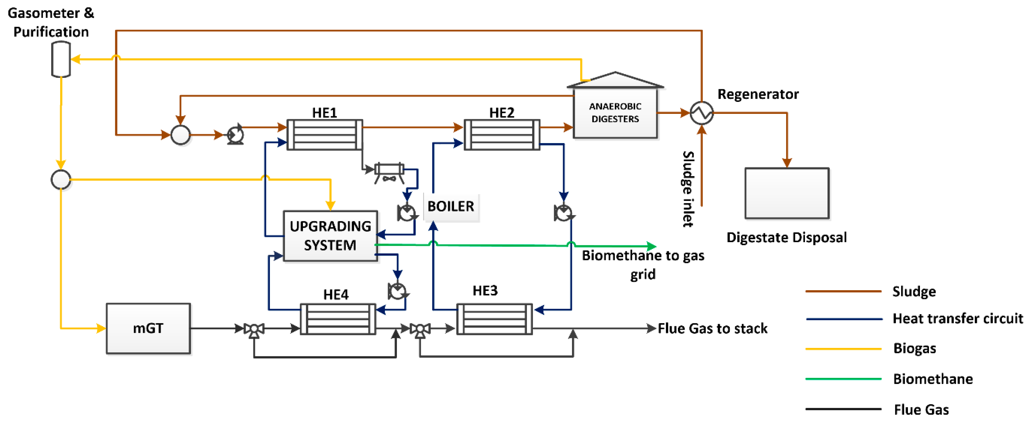
The plant considered in this study is located in Viareggio (Italy). The plant performs co-digestion of a mixture of civil sewage and organic waste (sludge henceforth), with a total mass flow rate of 8.8 ton/h (7% of solids) in two digesters of a total volume of about 4600 m3. The geometrical characteristics of the two digesters are reported in Table 1. Mesophilic digestion occurs, and sewage must be kept at the temperature of 37 °C. The biogas production is of 5656 Nm3/day, with a methane concentration of 65% (Vol.). After a revision of the original arrangement, the plant was made to operate with a Capstone C200 micro-gas turbine (mGT), fueled with biogas from the digesters and serving as a cogeneration unit to cover the thermal and electrical energy needs of the plant. Due to the recent opportunity to produce bio-methane, a purification and upgrading system was also considered, to convert a portion of biogas into bio-methane. As a reference upgrading unit, the bio-methane produced by GreenMethane and based on the absorption of CO2 in a hot solution of water and potassium carbonate was c onsidered [31]. To improve the solubility of CO2 and accelerate its separation from the biogas, the system operates at 120 °C and, therefore, requires thermal energy. It also requires electrical energy to circulate the solution and compress the biogas up to 8 barA. According to the manufacturer’s data, the upgrading system requires 0.2 kWhel/Nm3 and 0.59 kWhth/Nm3 of treated biogas. About 75% of the heat required during the CO2 absorption is available at a temperature of 80 °C during the solution regeneration and thus, may be used for sludge-heating. The scheme of the system, including the upgrading system, is reported in Figure 1.
The sludge is pumped into the plant and through a regenerator, which recovers thermal energy from the exhaust digestate before its disposal. After the regenerator, the sludge is mixed with a recirculating mass flow rate from the anaerobic digesters (recirculation ratio of 23:1) and then enters the heating section. This section is made up of two heat exchangers: The first one (HE1) takes advantage of the thermal power recovered from the upgrading system, while the second one (HE2) exploits the thermal power recovered from the micro-gas turbine. After being heated up at the digestion temperature (37 °C), the sludge flows to the digesters.
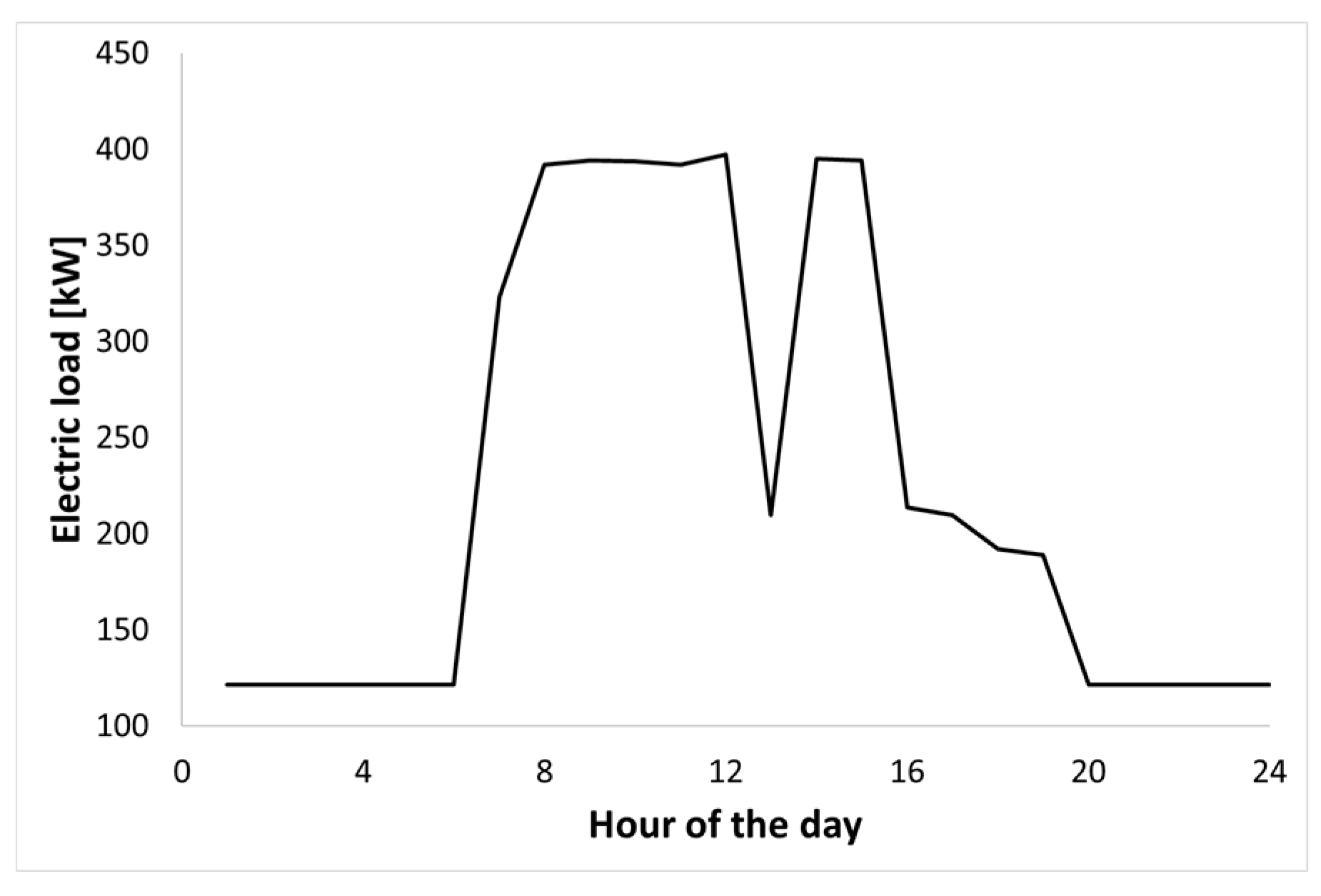
After the digestion process, digestate flows into the regenerator to provide useful heat to the sludge entering the plant and then is discharged. Biogas is stored in a gasometer and, after a cleaning station to remove H2S, is sent partly to the micro-gas turbine (mGT) for power and heat production and partly to the upgrading system for CO2 removal. The mGT exhaust gas flows firstly into a heat exchanger, to provide heat to the upgrading system (HE4), and then into a second heat exchanger (HE3), to provide thermal power to the sludge. A diverter is used to regulate the heat transfer with the sludge, thus keeping the temperature of digestion constantly at 37 °C. A cooler is also included in the plant, in case the power recovered from the upgrading systems is greater than that required by the sludge. An auxiliary boiler on the sludge-heating circuit is used to provide energy during days when the thermal requirement of the sludge is high and the thermal power from the mGT is not sufficient to keep its temperature. The boiler is fueled by natural gas. The choice of fueling the boiler with natural gas, rather than with biogas, is justified from both an economic and a technical point of view: The cost of natural gas is much lower than the price of bio-methane when injected into the grid, due to government incentives. In addition, this choice allows one to operate the upgrading system with a constant amount of biogas and, thus, at its design point. In this way, performance reductions, which may decrease the CO2 removal capacity and increase the methane slip, are avoided. The plant has a certain consumption of electricity for the preparation and handling of organic waste and sewage. The reference daily load is reported in Figure 2 and was provided by the plant manager. This load does not include the consumption of the upgrading system (about 0.2 kWh/Nm3 of biogas).
3. Materials and Methods
A model, which considers the off-design performance of the plant, has been developed to assess the annual behavior of the system for different amounts of biogas treated by the upgrading system (from 140 to 180 Nm3/h, corresponding to 60–75% of the total biogas produced). The biogas that is not treated in the upgrading system is used in the mGT to provide heat and electrical energy to the plant. Therefore, by changing the amount of biogas treated in the upgrading system, the mGT load conditions also change.
3.1. Thermodynamic Analysis
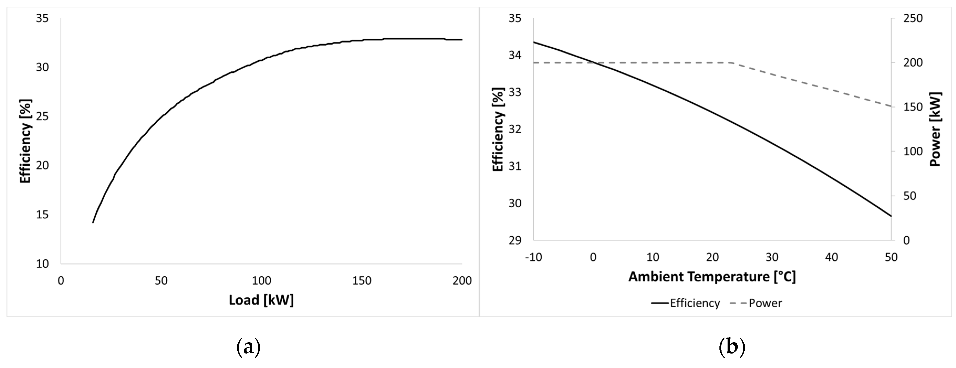
The anaerobic digestion plant of Viareggio was made to operate with a C200 Capstone micro-gas turbine. The efficiency curve, as a function of the load, is reported in Figure 3a. The influence of ambient temperature on the micro-gas turbine power output and efficiency is shown in Figure 3b. The exhaust gas mass flow rate and temperature were also considered as functions of the load and ambient temperature and were provided by the micro-gas turbine manufacturer [32].
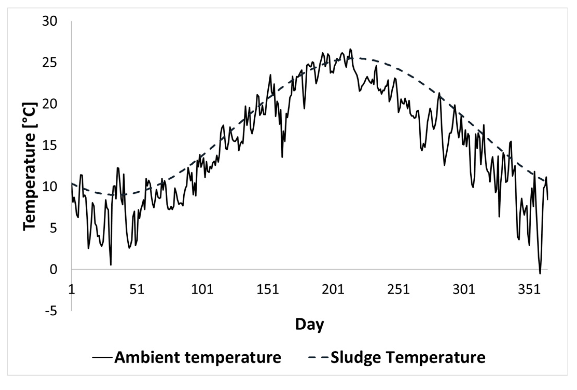
The daily average ambient temperature and sludge temperature in Viareggio were considered as reported in Figure 4.
The first temperature was measured and averaged from [33], whereas the second temperature was provided by the plant manager. The heat required to warm-up the sludge was estimated as:
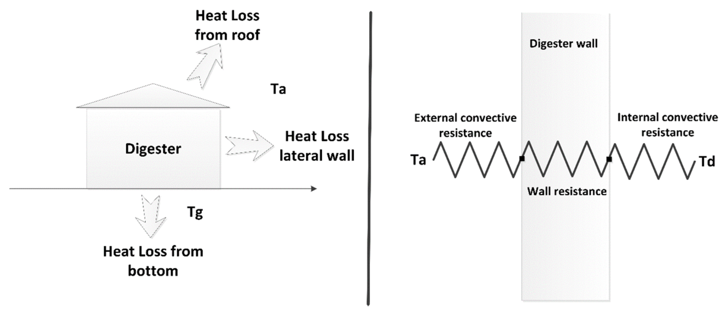
where is the mass flow rate of the sludge entering the plant, is the specific heat of the sludge, is the digestion temperature, and is the temperature at the regenerator outlet. The total heat required by the digester was estimated by considering the thermal losses of the two digesters. Since the diameter of the digesters was much larger than the wall thickness, the flat wall approximation was used to calculate the overall heat transfer coefficient and the total heat exchanged with the external air and the ground:
where is the overall heat transfer coefficient, A is the surface of the digester, is the ambient temperature (Figure 5), and is the ground temperature (kept constant at 20 °C throughout the year). The subscripts w, t, and g refer to the lateral walls, the top, and the foundations of the two digesters, respectively.
The total thermal power required by the digestion process is, therefore, the sum of the losses of thermal power and the thermal power required to heat the sludge:
Obviously, the size of the sludge regenerator influences the amount of total thermal power required since it modifies the value of the temperature . In this study, a countercurrent shell and tube heat exchanger with a constant surface of 30 m2 was used. All heat exchangers were simulated by taking into account the ε-NTU method for the estimation of off-design performance. The temperature at the regenerator outlet () was then estimated and Equation (1) was solved:
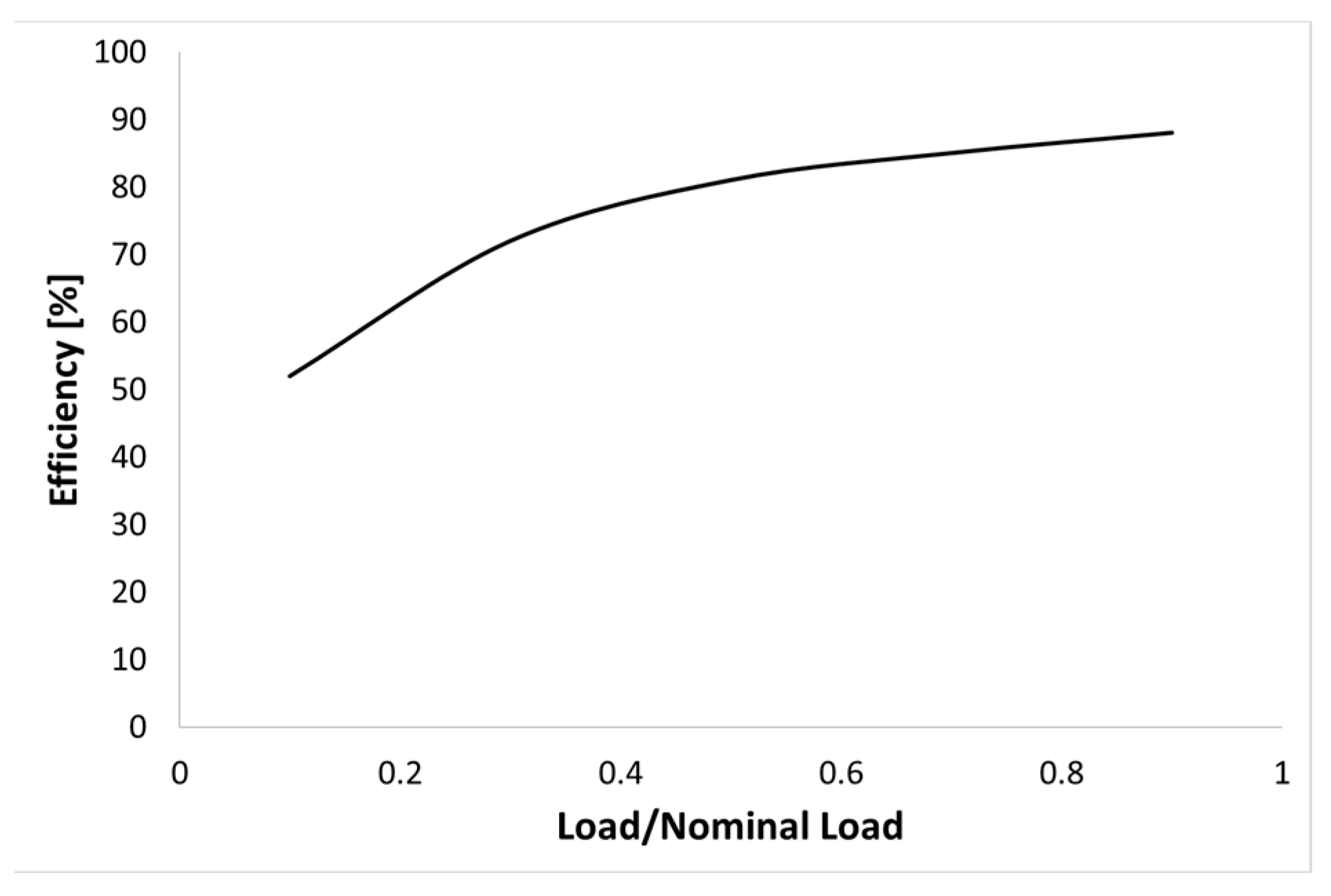
where is the sludge temperature at the plant inlet, is the efficacy of the heat exchanger (a function of NTU), and is the regenerator surface. For the auxiliary boiler, an efficiency curve from the literature was used (Figure 6) to estimate the off-design performance [34]. Since the upgrading system is operated at a constant biogas mass flow rate, the nominal loads declared by the manufacturer were used.
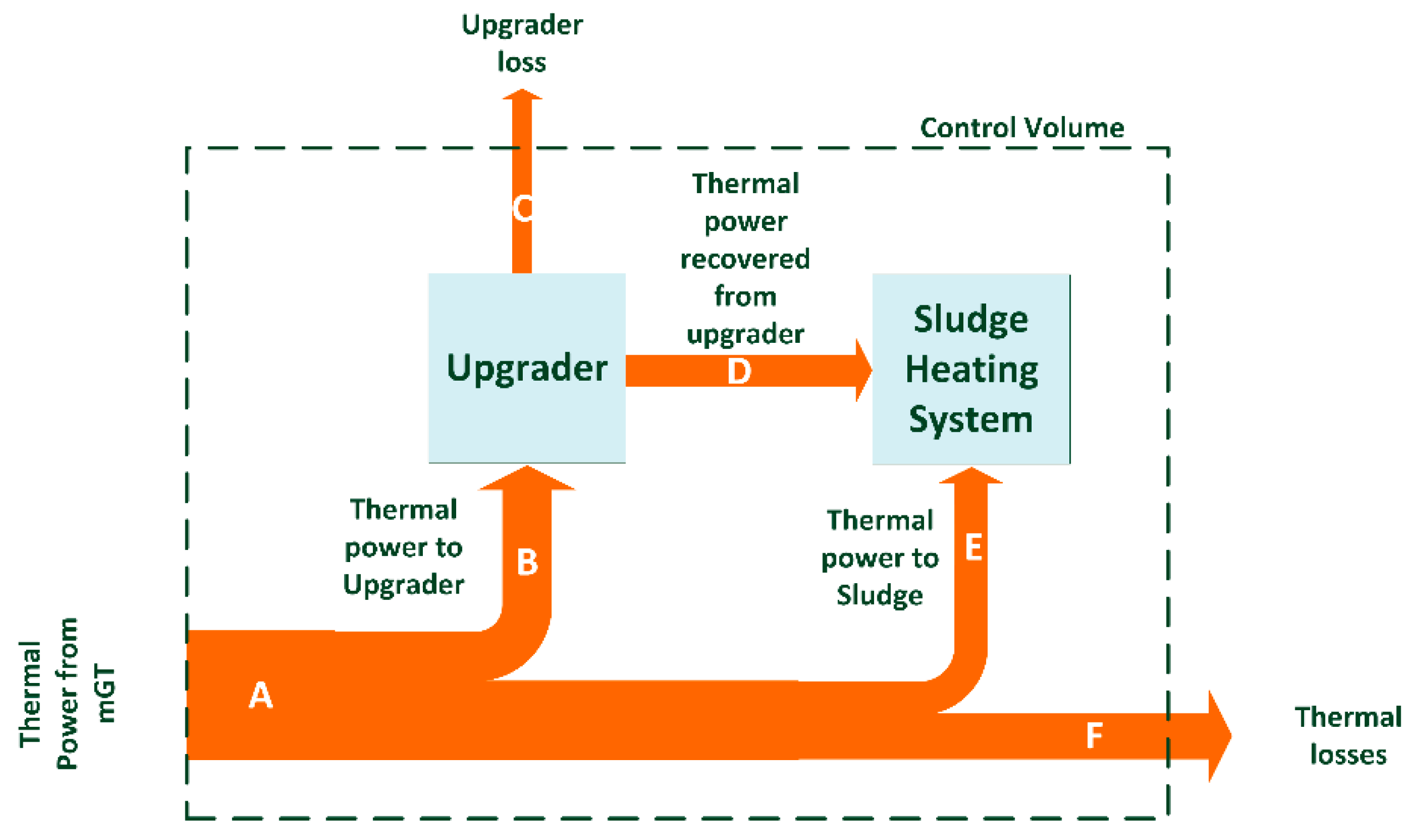
The thermal energy distribution in the plant is quite complex, as there is a strong interconnection between the generator and the users (Figure 7). The thermal energy from the micro-gas turbine is firstly recovered in the upgrading system and then in the sludge-heating. In addition, 75% of the heat provided to the upgrading system is recovered and used to preheat the sludge. Therefore, thermal losses may be calculated as:
where is the mass flow rate of the exhaust gasses, is the average specific heat of the exhaust gasses, is the exhaust gas temperature at the base of the stack, is a reference temperature kept equal to 20 °C and is the loss of the upgrading system. Therefore, by indicating with the available thermal power in the mGT exhaust gasses, the recovery efficiency of the co-generator is estimated as:
where is the available thermal power contained in the flue gas, i.e. the thermal power which could be extracted if the exhaust gas could be cooled down to reference ambient conditions (20 °C). In other words:
where is the exhaust gas temperature at the mGT outlet and is 20 °C.
The equations were solved by means of a Visual Basic (VBA) routine that calculates sludge temperatures after the regenerator and mixing. An iteration procedure was used to estimate the mGT power output and the exhaust gas conditions (temperature and mass flow rate) as a function of the available biogas. Starting from the exhaust gas conditions, the epsilon-NTU method was used to calculate the outlet temperature of the exhaust gas flowing in HE4 as a function of the heat required by the upgrading system. Then the amount of heat recovered by the upgrading system was estimated and the sludge outlet temperature from HE1 was calculated. A second iterative loop determined the amount of heat exchanged in HE3 to bring the sludge to the desired temperature by also considering the digesters’ thermal losses. After the evaluation of these quantities, all the other variables were simply directly estimated by means of the explicit equation reported in this section.
3.2. Economic Analysis
The economic analysis was carried out by using the micro-gas turbine, upgrading system, and heat exchanger costs. The mGT module cost was provided by the plant manager and a specific cost of about 1800 $/kW was used. The upgrading system cost was provided by the manufacturer and is about 1 M$ for a capacity of 170 Nm3/h. To scale this cost according to the capacity, a power law was adopted:
where is the cost in the reference conditions, is the reference capacity, and is the actual capacity. The costs of the heat exchangers were calculated by using the cost functions reported in [35]. The purchased equipment cost was estimated as (A is the heat exchanger area and are constants, depending on the type of heat exchanger):
The final cost (bare module cost) was estimated by considering the pressure and material factors, according to the procedure reported in [35]. When the electrical energy produced is not enough to cover the plant needs, electrical energy is purchased from the grid. A constant cost of 0.15 $/kWh was used. Bio-methane and electrical power surpluses are the revenues of the plant. For the first one, several selling prices were considered, whereas a selling price of 0.04 $/kWh was assumed for the second one. Therefore, the net present value (NPV) was calculated as:
where is the capital cost of the system (CapEx), is the revenue at the i-th year, and is the operative costs (OpEx) at the i-th year. Among the operative costs, besides the electrical energy and natural gas costs, operations and maintenance (O&M) were considered as 2.5% of the capital cost.
4. Results
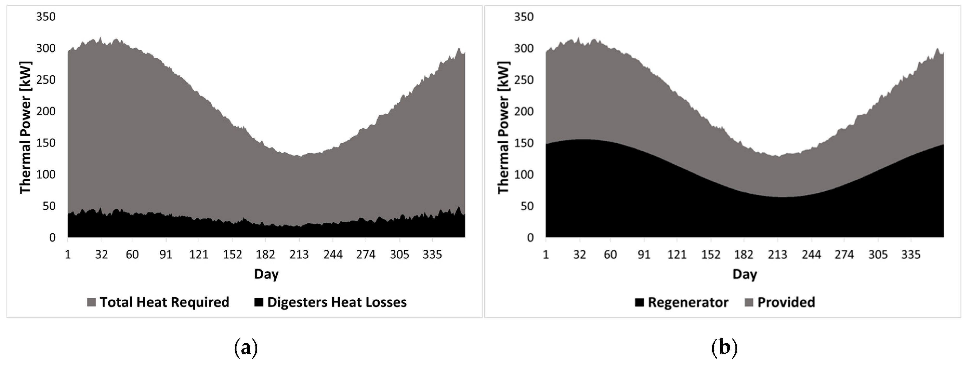
As stated above, the digester requires a continuous thermal input to keep the mesophilic digestion process active. Most of the heat is due to sludge-heating and only a minor contribution is due to digester heat losses (Figure 8a). In general, a reduction in the thermal requirements for sludge-heating corresponds with a reduction of biogas consumption in the co-generation unit and, therefore, a larger amount of biogas available for conversion into bio-methane. By using a 30 m2 heat exchanger, it was possible to recover heat from the digestate and reduce the amount of heat required to keep the digester in temperature (Figure 8b, grey area).
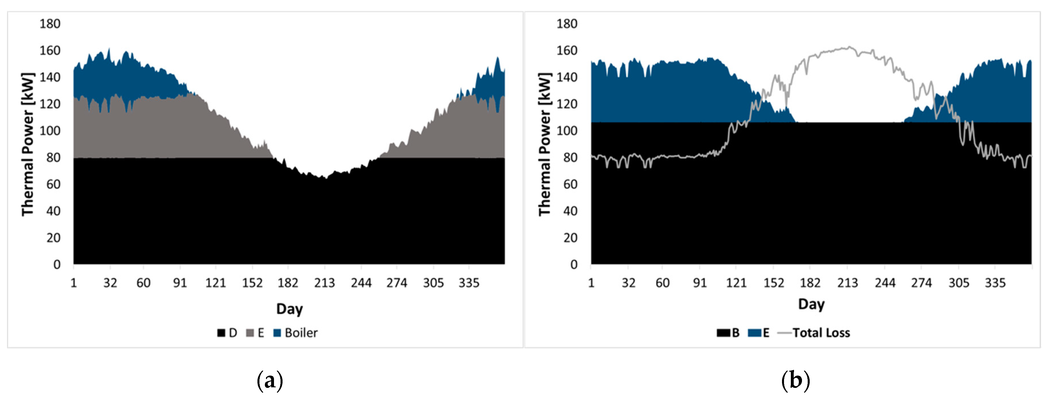
The micro-gas turbine provides thermal power to both the upgrading system and the sludge-heating circuits. Approximately 75% of the absorbed thermal power may be recovered from the upgrading unit to preheat the sludge (Figure 7). In Figure 9a, the different components of thermal energy that contribute to sludge-heating are reported. In Figure 9b, the repartition of the mGT thermal power content is depicted. Both figures are in reference to an upgrading unit size of 180 Nm3/h (capital letters B, D, and E refer to the fluxes reported in Figure 7).
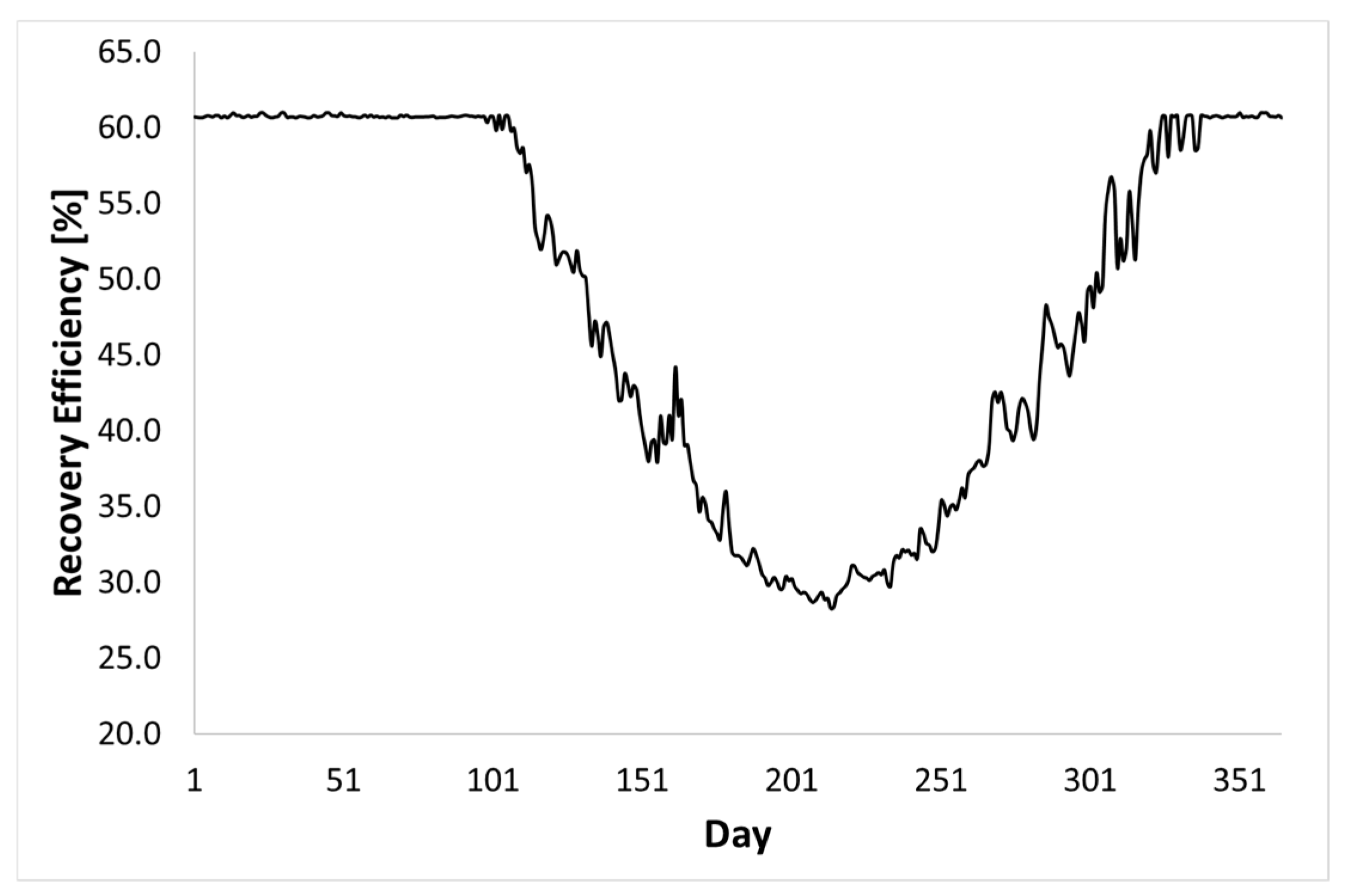
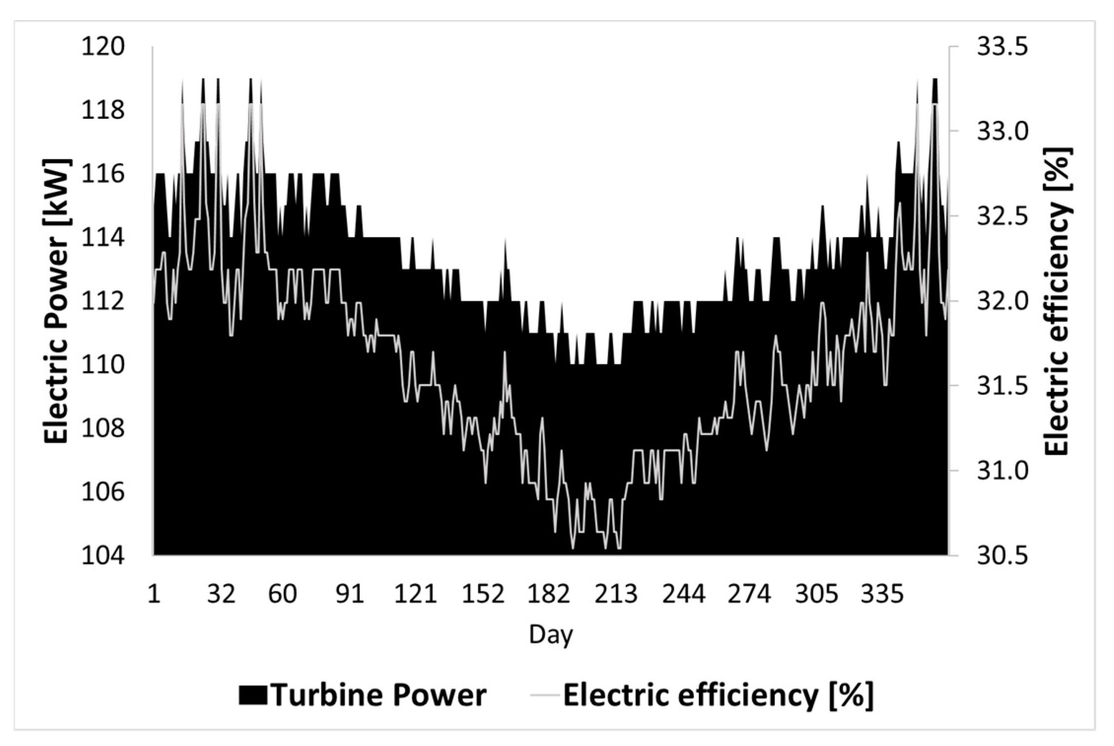
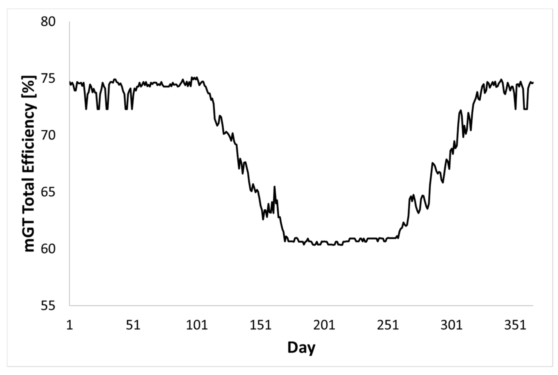
The total thermal power required by the system is related to the thermal requirement of the upgrader and the sludge-heating. The actual total load that has to be provided to the system is lower than the simple sum of the two requirements, as there is a contribution of thermal energy recovered from the upgrader. This quantity ranges between a maximum of 80 kW during winter and a minimum of 64 kW in summer (black area of Figure 9a). During winter, when both the sludge and ambient temperatures are very low, the sum of the thermal power provided by the mGT and that recovered from the upgrading system are not sufficient to keep the sludge at the digestion temperature. Boiler integration is, therefore, necessary to operate the system (blue area of Figure 9a). Conversely, during summer, the thermal power recovered from the upgrading system is sufficient for sludge-heating (part of the recovered thermal power dissipated during summer, as shown in Figure 9a). In this case, the exhaust gasses from the mGT are diverted and the sludge-heating circuit is bypassed. It is worth noting that losses (Figure 9b) increase during the mid-season and summer period due to both the mGT diverter operation, which increases the temperature of the exhaust gas at the stack, and the dissipation of recovered thermal power in the upgrading system. The recovery efficiency of the system is therefore maximum during winter and decreases during summer (Figure 10). During winter, the trend is almost constant since the mass flow rate from the mGT interacts with heat exchangers (no diverter operation). By increasing the sludge and ambient temperature, the heat requirement decreases and the mGT diverter progressively increases the amount of exhaust gas that bypasses the heat exchanger and goes directly to the stack. Electrical power from the mGT and its efficiency has the same trend (Figure 11), as they are strictly related to the ambient temperature (the mGT is operated with a constant biogas flow rate). The total efficiency of the mGT is maximal during winter (high electrical and thermal efficiency) and minimal and almost constant during the summer period when the sludge-heating circuit is bypassed (Figure 12).
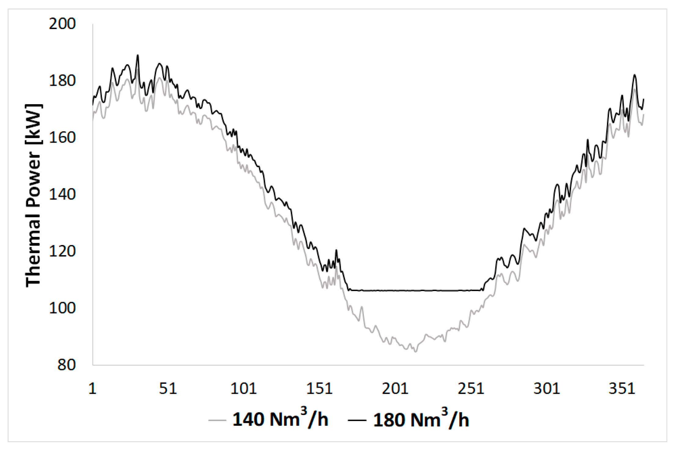
The heat recovered from the cogeneration system is a function of the size of the upgrading unit. The lower the upgrader size, the lower the thermal power that is required for its operation and the lower the recovered thermal energy is (Figure 13). When bio-methane production is low, thermal energy recovery from the upgrader might not be sufficient to keep the sludge at the desired temperature during summer. By decreasing bio-methane production, the mGT fuel-input increased, with a resulting increase in both electricity and the thermal power output.
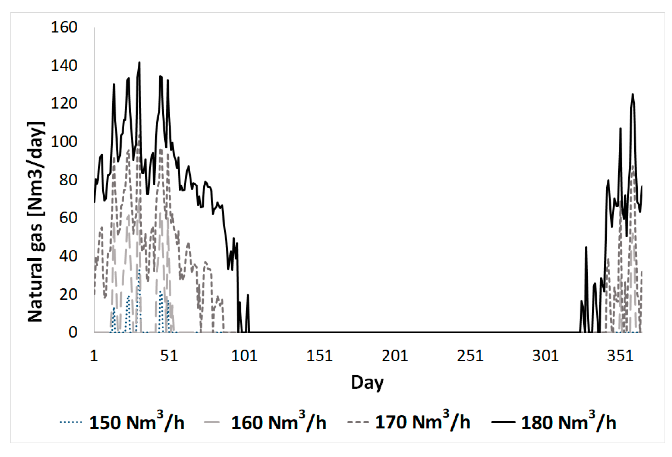
The micro-gas turbine performance has a strong influence on the entire system. If the thermal power produced by the turbine is not enough to satisfy the digester and upgrading system needs, the process is not self-sustaining, from a thermal point of view, and an external integration from an auxiliary boiler is required (fueled by natural gas). Figure 14 shows that the system is thermally self-sustaining for the whole year if the upgrading system size is below 150 Nm3/h, corresponding to about 64% of the biogas produced by the digester.
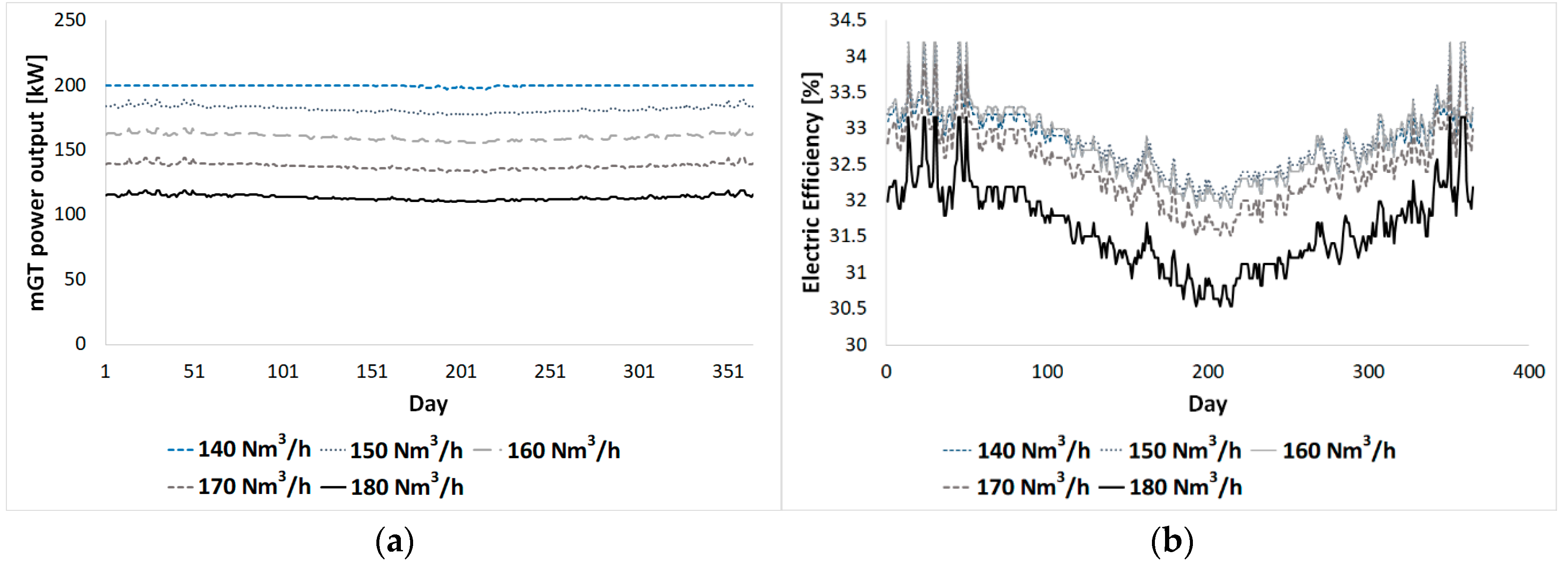
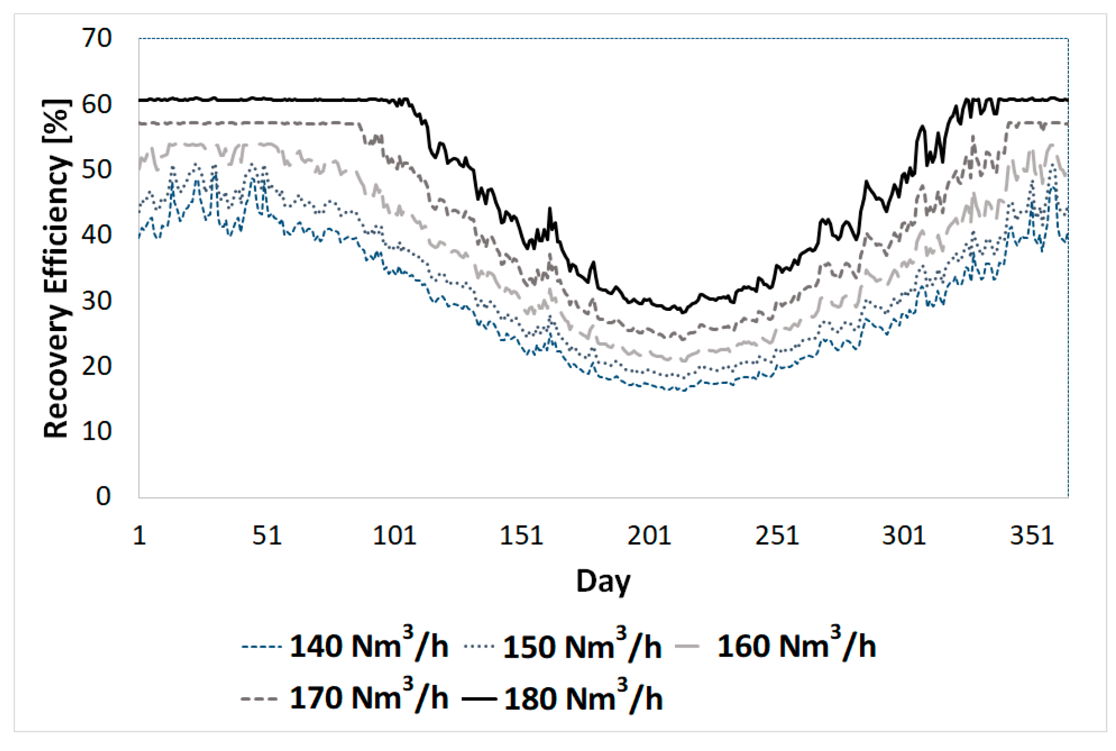
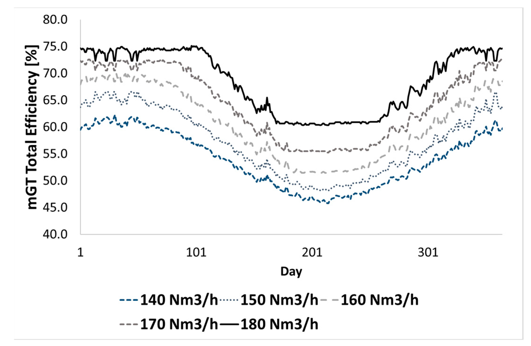
The high production of bio-methane requires the external integration of natural gas and minimizes both the electrical efficiency and power output (Figure 15), due to the part load operation of the mGT, but maximizes the recovery efficiency of the mGT and upgrading system (Figure 16). For this reason, the total efficiency of the mGT is maximal for the highest sizes of the upgrading unit (Figure 17).
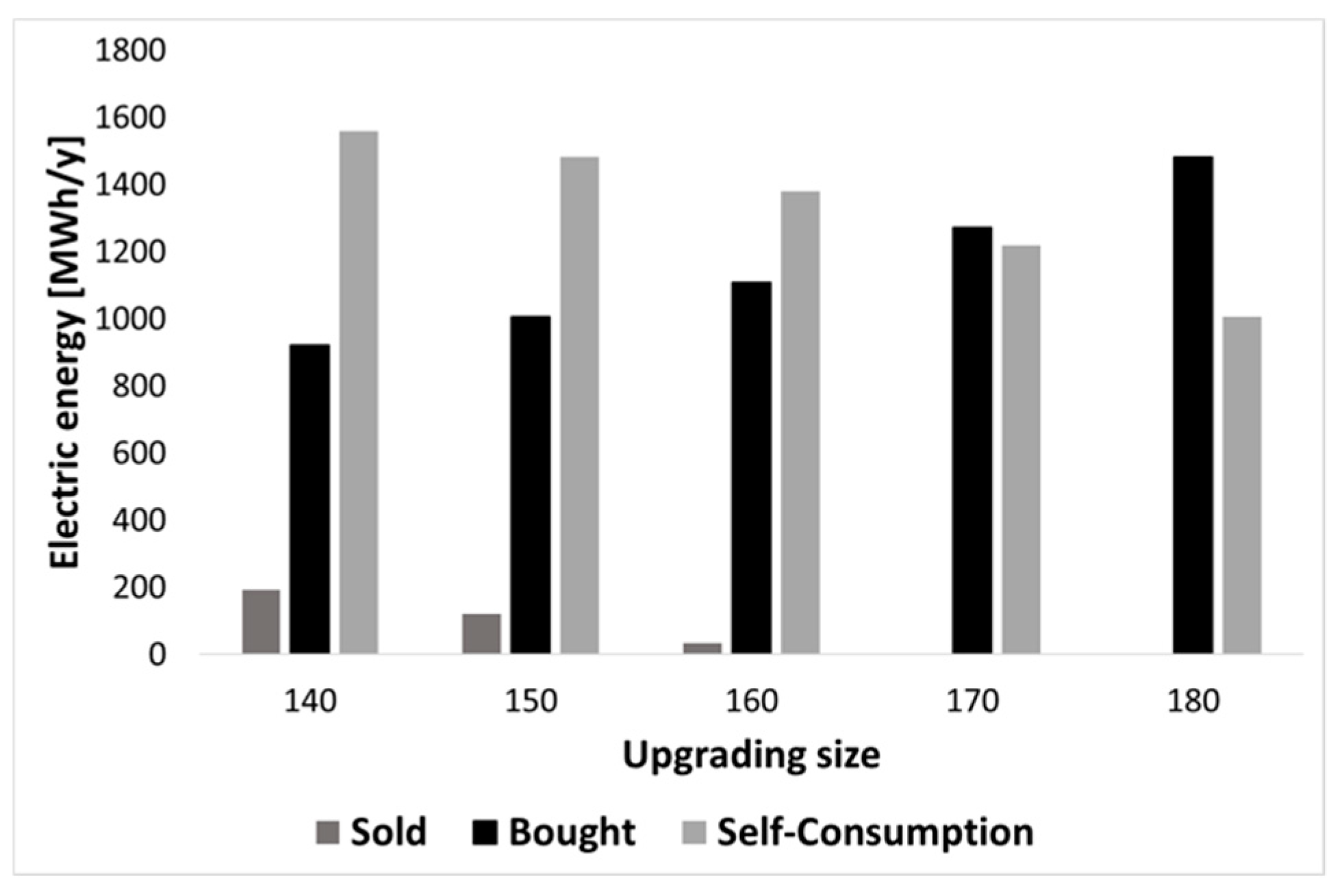
From an electrical point of view, both the production and consumption depend on the amount of biogas treated. Figure 18 shows the capability of the cogeneration unit to cover the electrical load. It can be observed that both the electrical energy sold to the grid and the self-consumed electrical energy decrease with the upgrading system size, due to the mGT power output decrease (a lower amount of biogas is available for the turbine). Conversely, the amount of energy bought from the grid always increases with the size of the upgrading system for two main reasons:
- The mGT output power decreases, due to the lower amount of biogas.
- The electric energy requirement of the upgrading system increases as the amount of biogas treated increases.
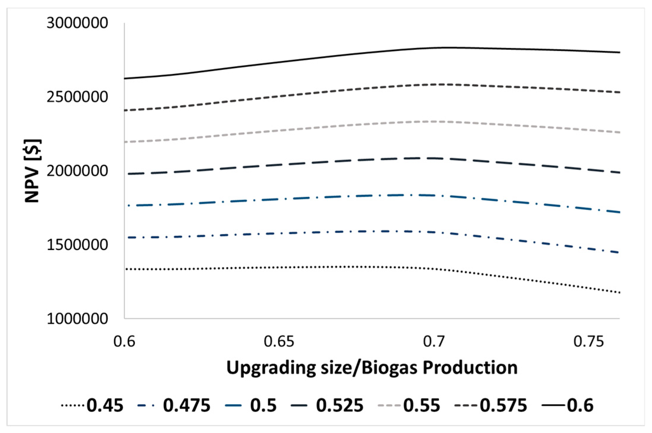
To quantify the best size of the upgrading unit, an economic analysis is necessary. To generalize the outcomes of the study, the results are shown as fractions of the amount of biogas treated in the upgrading system and the total biogas production. In the case of a selling price of 0.55 $/m3, the optimal upgrading size is around 70% of the total biogas production. For different selling prices of bio-methane, the net present value (NPV) after 20 years, which is estimated according to Equation (7), is reported in Figure 19. If the bio-methane selling price is below 0.45 $/m3, the size of the upgrading system should be as low as possible. For selling prices above this threshold, the optimal upgrading size moves towards the highest value of the range considered and is around 165 Nm3/h (68–72% of the plant biogas production).
5. Conclusions
In this study, the integration of an upgrading system for bio-methane production in a biogas plant equipped with a cogeneration unit is investigated in detail. The anaerobic digestion plant of Viareggio has been considered as a case study. The plant produces biogas and is equipped with a cogeneration unit. A model, which considers the off-design performance of the components, has been developed and used to simulate the plant over one year, with actual ambient conditions. Different upgrading system sizes were tested to identify the optimal combination with the plant. The analysis showed the importance of sludge regeneration, to reduce the thermal power requirements of the digester and minimize the amount of external natural gas. The behavior of the cogeneration unit as a function of the upgrading size was shown: The electrical efficiency and power output of the mGT decreased with the upgrading size, whereas the recovery efficiency and total efficiency were characterized by an opposite trend. For upgrading units processing large amounts of biogas, a certain amount of natural gas is necessary to drive an auxiliary boiler, which provides the necessary thermal power for the digestion process. In addition, by increasing the upgrading size, the amount of electrical energy required by the plant increases, until the electrical energy sold to the grid is zero. The economic analysis showed that the optimal ratio between the size of the upgrading unit and the total plant production strongly depends on the bio-methane price; if the price is below 0.45 $/Nm3, the size should be as low as possible.
Author Contributions
Methodology, A.B.; software, A.B., R.G., and O.Y.; investigation, A.B., L.F., R.G., and O.Y.; writing—original draft preparation, A.B., R.G., and O.Y.; writing—review and editing, A.B. and L.F.; supervision, L.F., U.D., and F.V.; funding acquisition, L.F. and F.V.
Funding
This research is part of the project BIO2ENERGY funded by MIUR-Regione Toscana DGRT 1208/2012 and MIUR-MISE-Regione Toscana DGRT 758/2013 PAR FAS 2007-2013- Linea d’Azione 1.1 in sub-program FAR-FAS 2014.
Acknowledgments
The authors would like to thank Caterina Susini and the staff of SEA Risorse for the support provided to this research.
Conflicts of Interest
The authors declare no conflicts of interest.
Nomenclature
| Thermal Power [kW] | |
| T | Temperature [°C] |
| U | Overall heat transfer coefficient [W K−1m−2] |
| A | Surface [m2] |
| ε | Heat exchanger efficacy |
| Mass Flow rate [kg/s] | |
| Thermal Loss [kW] | |
| є | Recovery efficiency |
| Constant pressure specific heat [kJ kg−1 K−1] | |
| C | Cost [$] |
| R | Revenue [$] |
| PEC | Purchased Equipment Cost [$] |
| NPV | Net present value [€] |
| Subscripts | |
| h | Heat up |
| s | Sludge |
| d | Digesters |
| r | Regenerator |
| w | Wall |
| t | Top |
| g | Ground |
| l | Loss |
| in | Inlet |
| fg | Flue Gas |
| St | Stack |
| 0 | Reference state |
| up | Upgrading unit |
| av | Available |
| mGT | From micro Gas Turbine |
References
- Share of Transport Fuel from Renewable Energy Sources—Product—Eurostat. Available online: https://ec.europa.eu/eurostat/web/products-eurostat-news/-/DDN-20180312-1 (accessed on 17 December 2018).
- Scarlat, N.; Dallemand, J.-F.; Fahl, F. Biogas: Developments and perspectives in Europe. Renew. Energy 2018, 129, 457–472. [Google Scholar] [CrossRef]
- Cavinato, C.; Bolzonella, D.; Pavan, P.; Fatone, F.; Cecchi, F. Mesophilic and thermophilic anaerobic co-digestion of waste activated sludge and source sorted biowaste in pilot- and full-scale reactors. Renew. Energy 2013, 55, 260–265. [Google Scholar] [CrossRef]
- Pecorini, I.; Bacchi, D.; Albini, E.; Baldi, F.; Galoppi, G.; Rossi, P.; Paoli, P.; Ferrari, L.; Carnevale, E.A.; Peruzzini, M.; et al. The Bio2energy Project: Bioenergy, Biofuels and Bioproducts from Municipal Solid Waste and Sludge. In Proceedings of the 25th European Biomass Conference and Exhibition, Stockholm, Sweden, 12–15 June 2017; pp. 70–77. [Google Scholar]
- Nghiem, L.D.; Koch, K.; Bolzonella, D.; Drewes, J.E. Full scale co-digestion of wastewater sludge and food waste: Bottlenecks and possibilities. Renew. Sustain. Energy Rev. 2017, 72, 354–362. [Google Scholar] [CrossRef]
- Urban, W. Biomethane injection into natural gas networks. In The Biogas Handbook; Elsevier: Amsterdam, The Netherlands, 2013; pp. 378–403. [Google Scholar]
- Stan, C.; Collaguazo, G.; Streche, C.; Apostol, T.; Cocarta, D.; Stan, C.; Collaguazo, G.; Streche, C.; Apostol, T.; Cocarta, D.M. Pilot-Scale Anaerobic Co-Digestion of the OFMSW: Improving Biogas Production and Startup. Sustainability 2018, 10, 1939. [Google Scholar] [CrossRef]
- Eder, A. Measuring and decomposing economies of diversification: An application to biogas-fuelled cogeneration plants in Austria. Int. J. Prod. Econ. 2018, 204, 421–432. [Google Scholar] [CrossRef]
- Pecorini, I.; Ferrari, L.; Baldi, F.; Albini, E.; Galoppi, G.; Bacchi, D.; Vizza, F.; Lombardi, L.; Carcasci, C.; Ferrara, G.; et al. Energy recovery from fermentative biohydrogen production of biowaste: A case study based analysis. Energy Procedia 2017, 126, 605–612. [Google Scholar] [CrossRef]
- Qian, Y.; Sun, S.; Ju, D.; Shan, X.; Lu, X. Review of the state-of-the-art of biogas combustion mechanisms and applications in internal combustion engines. Renew. Sustain. Energy Rev. 2017, 69, 50–58. [Google Scholar] [CrossRef]
- Sung, T.; Kim, S.; Kim, K.C. Thermoeconomic analysis of a biogas-fueled micro-gas turbine with a bottoming organic Rankine cycle for a sewage sludge and food waste treatment plant in the Republic of Korea. Appl. Ther. Eng. 2017, 127, 963–974. [Google Scholar] [CrossRef]
- Astals, S.; Venegas, C.; Peces, M.; Jofre, J.; Lucena, F.; Mata-Alvarez, J. Balancing hygienization and anaerobic digestion of raw sewage sludge. Water Res. 2012, 46, 6218–6227. [Google Scholar] [CrossRef] [PubMed]
- Lindkvist, E.; Johansson, M.; Rosenqvist, J.; Lindkvist, E.; Johansson, M.T.; Rosenqvist, J. Methodology for Analysing Energy Demand in Biogas Production Plants—A Comparative Study of Two Biogas Plants. Energies 2017, 10, 1822. [Google Scholar] [CrossRef]
- Rahman, M.A.; Møller, H.B.; Saha, C.K.; Alam, M.M.; Wahid, R.; Feng, L. Anaerobic co-digestion of poultry droppings and briquetted wheat straw at mesophilic and thermophilic conditions: Influence of alkali pretreatment. Renew. Energy 2018, 128, 241–249. [Google Scholar] [CrossRef]
- Lantz, M. The economic performance of combined heat and power from biogas produced from manure in Sweden—A comparison of different CHP technologies. Appl. Energy 2012, 98, 502–511. [Google Scholar] [CrossRef]
- Benato, A.; Macor, A.; Benato, A.; Macor, A. Biogas Engine Waste Heat Recovery Using Organic Rankine Cycle. Energies 2017, 10, 327. [Google Scholar] [CrossRef]
- Baccioli, A.; Ferrari, L.; Vizza, F.; Desideri, U. Feasibility analysis of coupling an ORC to a mGT in a biogas plant. In Proceedings of the ICAE2018: The 10th International Conference on Applied Energy, Hong Kong, China, 22–25 August 2018. [Google Scholar]
- Bruno, J.C.; Ortega-López, V.; Coronas, A. Integration of absorption cooling systems into micro gas turbine trigeneration systems using biogas: Case study of a sewage treatment plant. Appl. Energy 2009, 86, 837–847. [Google Scholar] [CrossRef]
- Gebrezgabher, S.A.; Meuwissen, M.P.M.; Prins, B.A.M.; Lansink, A.G.J.M.O. Economic analysis of anaerobic digestion—A case of Green power biogas plant in The Netherlands. NJAS 2010, 57, 109–115. [Google Scholar] [CrossRef] [Green Version]
- Pöschl, M.; Ward, S.; Owende, P. Evaluation of energy efficiency of various biogas production and utilization pathways. Appl. Energy 2010, 87, 3305–3321. [Google Scholar] [CrossRef]
- Baccioli, A.; Ferrari, L.; Pecorini, I.; Marchionni, A.; Susini, C.; Desideri, U. Feasibility analysis of a biogas-fuelled trigeneration plant operating with a mGT. In Proceedings of the ECOS 2018, Guimarães, Guimaraes, Portugal, 17–21 June 2018. [Google Scholar]
- Kim, S.; Chun Kim, K.; Kim, S.; Chun Kim, K. Performance Analysis of Biogas-Fueled SOFC/MGT Hybrid Power System in Busan, Republic of Korea. Proceedings 2018, 2, 605. [Google Scholar] [CrossRef]
- Aryal, N.; Kvist, T.; Aryal, N.; Kvist, T. Alternative of Biogas Injection into the Danish Gas Grid System—A Study from Demand Perspective. ChemEngineering 2018, 2, 43. [Google Scholar] [CrossRef]
- Hoo, P.Y.; Hashim, H.; Ho, W.S. Opportunities and challenges: Landfill gas to biomethane injection into natural gas distribution grid through pipeline. J. Clean. Prod. 2018, 175, 409–419. [Google Scholar] [CrossRef]
- Smyth, B.M.; Smyth, H.; Murphy, J.D. Determining the regional potential for a grass biomethane industry. Appl. Energy 2011, 88, 2037–2049. [Google Scholar] [CrossRef]
- Baccioli, A.; Caposciutti, G.; Ferrari, L.; Desideri, U. Poly-generation capability of a biogas plant with upgrading system. In Proceedings of the REM2018: Renewable Energy Integration with Mini/Microgrid, Rhodes, Greece, 28–30 September 2018. [Google Scholar]
- Hakawati, R.; Smyth, B.M.; McCullough, G.; De Rosa, F.; Rooney, D. What is the most energy efficient route for biogas utilization: Heat, electricity or transport? Appl. Energy 2017, 206, 1076–1087. [Google Scholar] [CrossRef]
- Ardolino, F.; Parrillo, F.; Arena, U. Biowaste-to-biomethane or biowaste-to-energy? An LCA study on anaerobic digestion of organic waste. J. Clean. Prod. 2018, 174, 462–476. [Google Scholar] [CrossRef]
- Lee, D.-H. Evaluation the financial feasibility of biogas upgrading to biomethane, heat, CHP and AwR. Int. J. Hydrog. Energy 2017, 42, 27718–27731. [Google Scholar] [CrossRef]
- Barbera, E.; Menegon, S.; Banzato, D.; D’Alpaos, C.; Bertucco, A. From biogas to biomethane: A process simulation-based techno-economic comparison of different upgrading technologies in the Italian context. Renewable Energy 2019, 135, 663–673. [Google Scholar] [CrossRef]
- GM Green Methane. Available online: http://www.gm-greenmethane.it/it-it/home (accessed on 29 December 2018).
- Capstone Turbine Corporation (CPST). Available online: https://www.capstoneturbine.com/ (accessed on 29 December 2018).
- CTI Comitato Termotecnico Italiano. Available online: https://try.cti2000.it/register.php (accessed on 29 December 2018).
- Boilers. Available online: https://www.designbuilder.co.uk/helpv5.2/Content/Boilers.htm (accessed on 29 December 2018).
- Turton, R.; Bailie, R.C.; Whiting, W.B.; Shaeiwitz, J.A.; Bhattacharyya, D. Analysis, Synthesis, and Design of Chemical Processes; Prentice Hall: Upper Saddle River, NJ, USA, 2012; ISBN 0132940299. [Google Scholar]
Figure 1.
The scheme of the anaerobic digestion plant.

Figure 2.
The electric load of the plant for sludge handling and preparation.

Figure 3.
The efficiency of the micro-gas turbine (mGT) with a variation of the load (a) and the influence of the ambient temperature on the efficiency and power output (b).
Figure 3.
The efficiency of the micro-gas turbine (mGT) with a variation of the load (a) and the influence of the ambient temperature on the efficiency and power output (b).

Figure 4.
The ambient and daily average sludge temperature.

Figure 5.
The heat transfer mechanism of the digesters.

Figure 6.
The auxiliary boiler efficiency curve as a function of the ratio between the actual load and the nominal load.
Figure 6.
The auxiliary boiler efficiency curve as a function of the ratio between the actual load and the nominal load.

Figure 7.
The thermal power flow scheme for the cogeneration system.

Figure 8.
The total heat required and digester losses (a) and the heat recovered in the regenerator (b).
Figure 8.
The total heat required and digester losses (a) and the heat recovered in the regenerator (b).

Figure 9.
The thermal power required to heat sludge divided by components (a) and the mGT exhaust gas thermal power contributions (b). Capital letters B, D, and E refer to Figure 7.
Figure 9.
The thermal power required to heat sludge divided by components (a) and the mGT exhaust gas thermal power contributions (b). Capital letters B, D, and E refer to Figure 7.

Figure 10.
The recovery efficiency of the system (upgrader size of 180 Nm3/h).

Figure 11.
The recovery efficiency of the system (upgrader size of 180 Nm3/h).

Figure 12.
The total efficiency of the micro-gas turbine (mGT) (upgrader size of 180 Nm3/h).

Figure 13.
The thermal power required by the system (upgrading and sludge) for two different values of upgrading unit size.
Figure 13.
The thermal power required by the system (upgrading and sludge) for two different values of upgrading unit size.

Figure 14.
The natural gas consumption in the auxiliary boiler for various sizes of upgrading system.
Figure 14.
The natural gas consumption in the auxiliary boiler for various sizes of upgrading system.

Figure 15.
The micro-gas turbine (mGT) power output (a) and electric efficiency (b) for various sizes of upgrading unit.
Figure 15.
The micro-gas turbine (mGT) power output (a) and electric efficiency (b) for various sizes of upgrading unit.

Figure 16.
The recovery efficiency for upgrading units of various sizes.

Figure 17.
The total efficiency for various bio-methane productions.

Figure 18.
Sold, bought and self-consumed energy as a function of the upgrading size.

Figure 19.
The net present value (NPV) after 20 years as a function of the ratio between the upgrading size and the total biogas production, for various bio-methane selling prices ($/m3).
Figure 19.
The net present value (NPV) after 20 years as a function of the ratio between the upgrading size and the total biogas production, for various bio-methane selling prices ($/m3).


Table 1.
The geometric characteristics of the digesters.
| - | Diameter [m] | Height [m] | External Surface [m2] | Reaction Volume [m3] |
|---|---|---|---|---|
| Digester 1 | 18 | 10.5 | 593.8 | 3300 |
| Digester 2 | 14 | 7 | 307.9 | 1300 |
© 2019 by the authors. Licensee MDPI, Basel, Switzerland. This article is an open access article distributed under the terms and conditions of the Creative Commons Attribution (CC BY) license (http://creativecommons.org/licenses/by/4.0/).
Share and Cite
MDPI and ACS Style
Baccioli, A.; Ferrari, L.; Guiller, R.; Yousfi, O.; Vizza, F.; Desideri, U. Feasibility Analysis of Bio-Methane Production in a Biogas Plant: A Case Study. Energies 2019, 12, 473. https://0-doi-org.brum.beds.ac.uk/10.3390/en12030473
AMA Style
Baccioli A, Ferrari L, Guiller R, Yousfi O, Vizza F, Desideri U. Feasibility Analysis of Bio-Methane Production in a Biogas Plant: A Case Study. Energies. 2019; 12(3):473. https://0-doi-org.brum.beds.ac.uk/10.3390/en12030473
Chicago/Turabian StyleBaccioli, Andrea, Lorenzo Ferrari, Romain Guiller, Oumayma Yousfi, Francesco Vizza, and Umberto Desideri. 2019. "Feasibility Analysis of Bio-Methane Production in a Biogas Plant: A Case Study" Energies 12, no. 3: 473. https://0-doi-org.brum.beds.ac.uk/10.3390/en12030473
Note that from the first issue of 2016, this journal uses article numbers instead of page numbers. See further details here.