A Multi-Agent System for Smart Energy Management Devoted to Vehicle Applications: Realistic Dynamic Hybrid Electric System Using Hydrogen as a Fuel


Abstract
:1. Introduction
- ✓
- smooth and delicate Hybrid ZEV system operation to enhance its relevant reacts against unexpected H2 gas fuel depletion;
- ✓
- collaboration between system components by applying the mult-iagent strategy to achieve a rapid and effective response of the system against any constraint;
- ✓
- fuel consumption prediction according to a chosen runway to be traveled for appropriate algorithm selecting; and
- ✓
- Emergency state treatment with appropriate cases when the system becomes unable to withstand the great shortage of hydrogen reserve that can cause its immediate shutdown.
2. Literature Review and Contributions
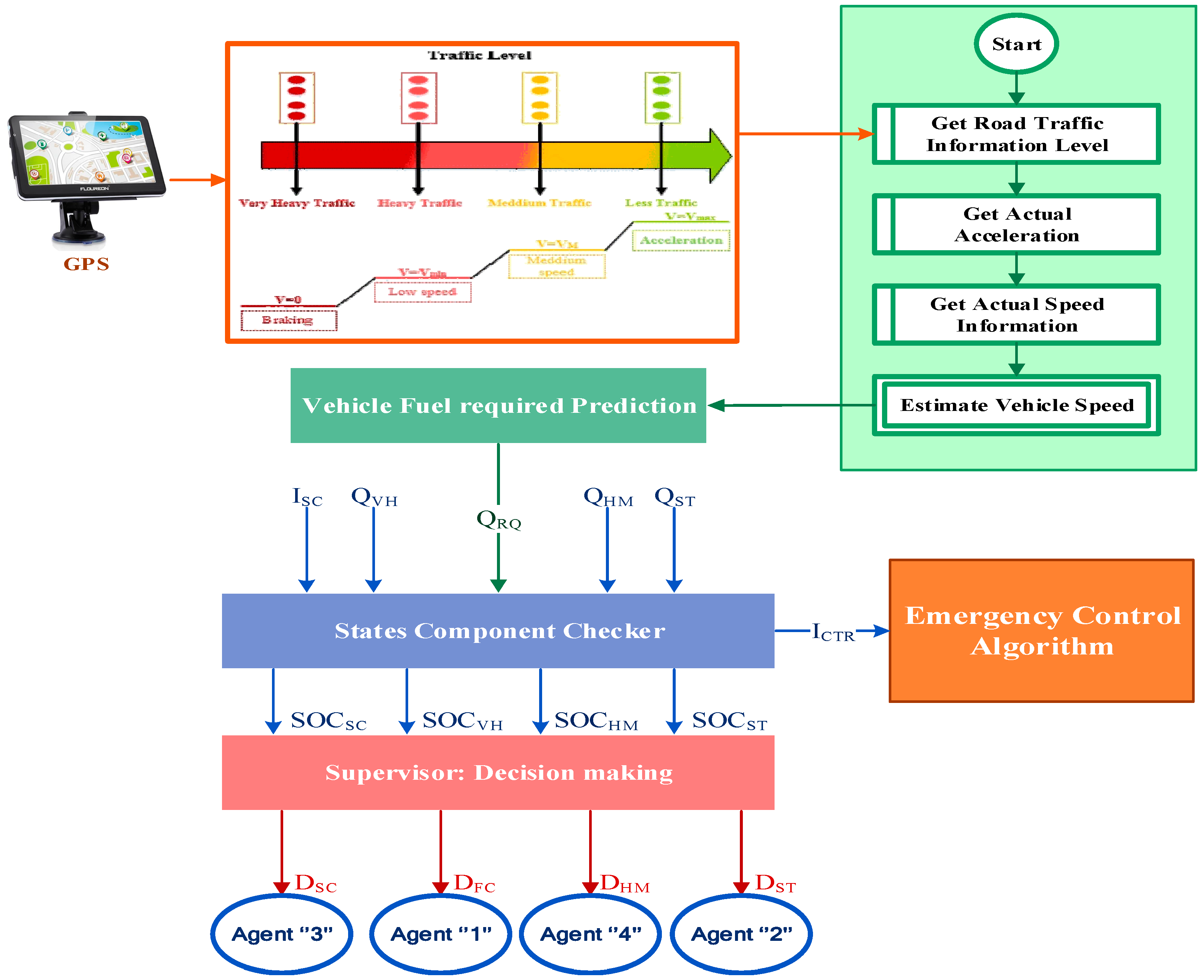
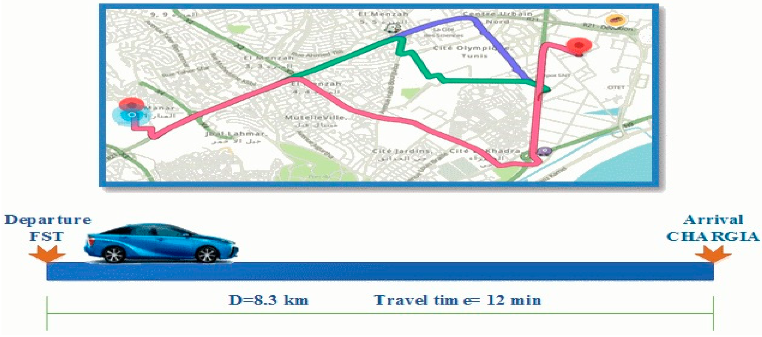
- Control the vehicle needs relying on a specific destination characteristics taking from Global Positioning System (GPS);
- Control energy distribution flows to fix each agent task;
- Achieve safe operation of all system components; and
- Conduct real-time performance analysis.
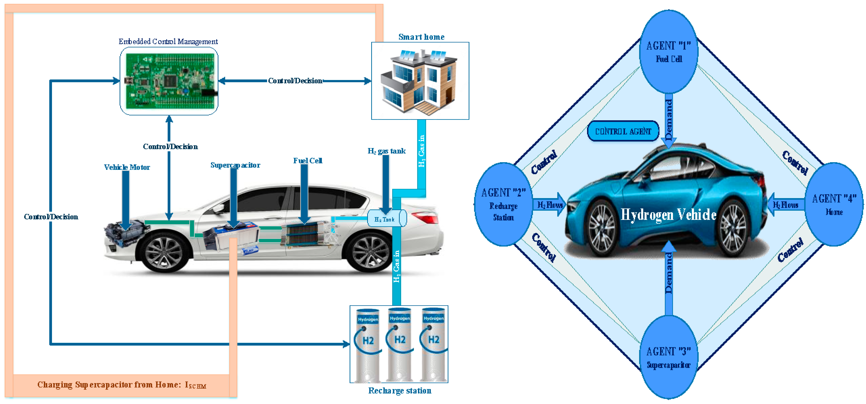
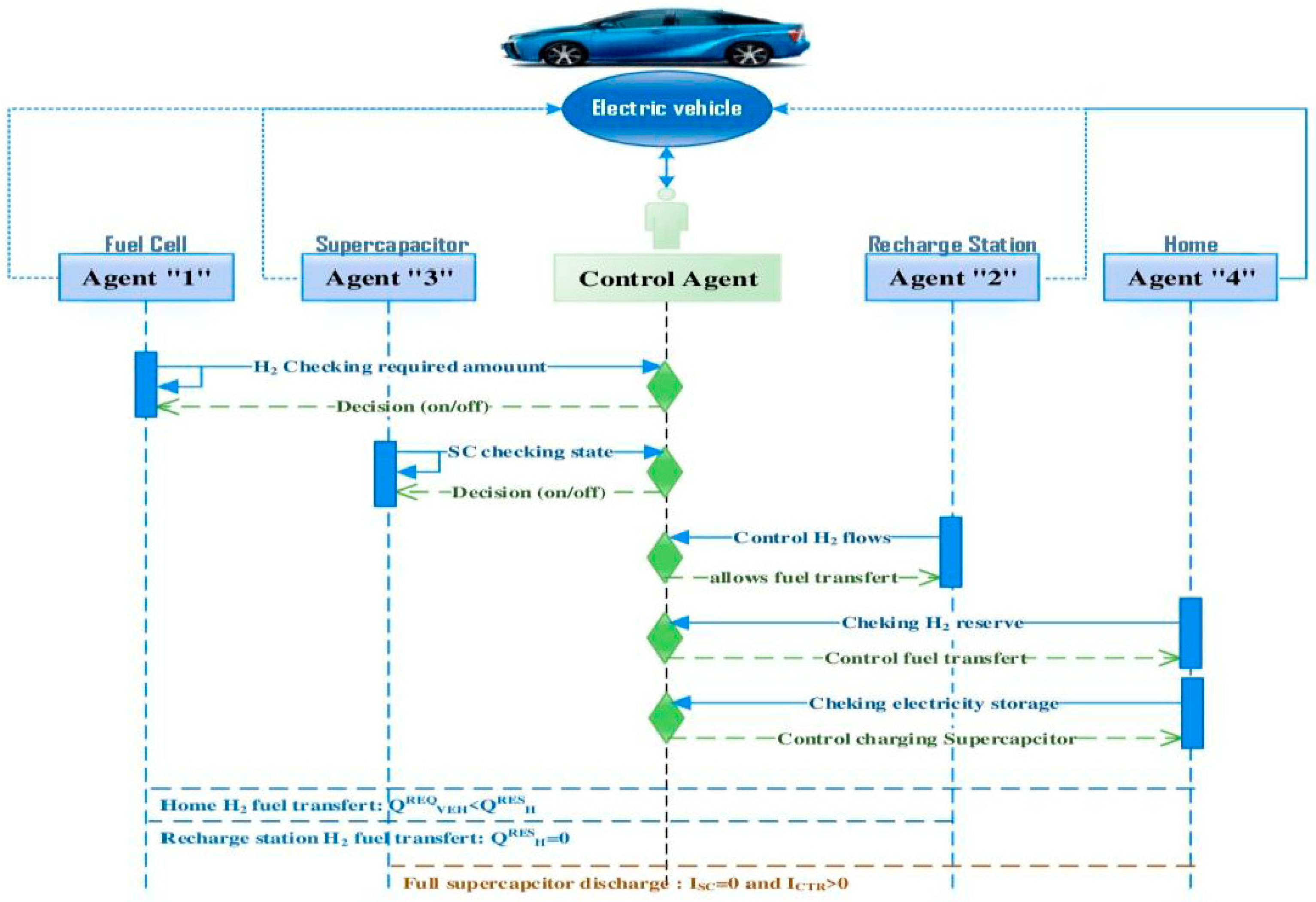
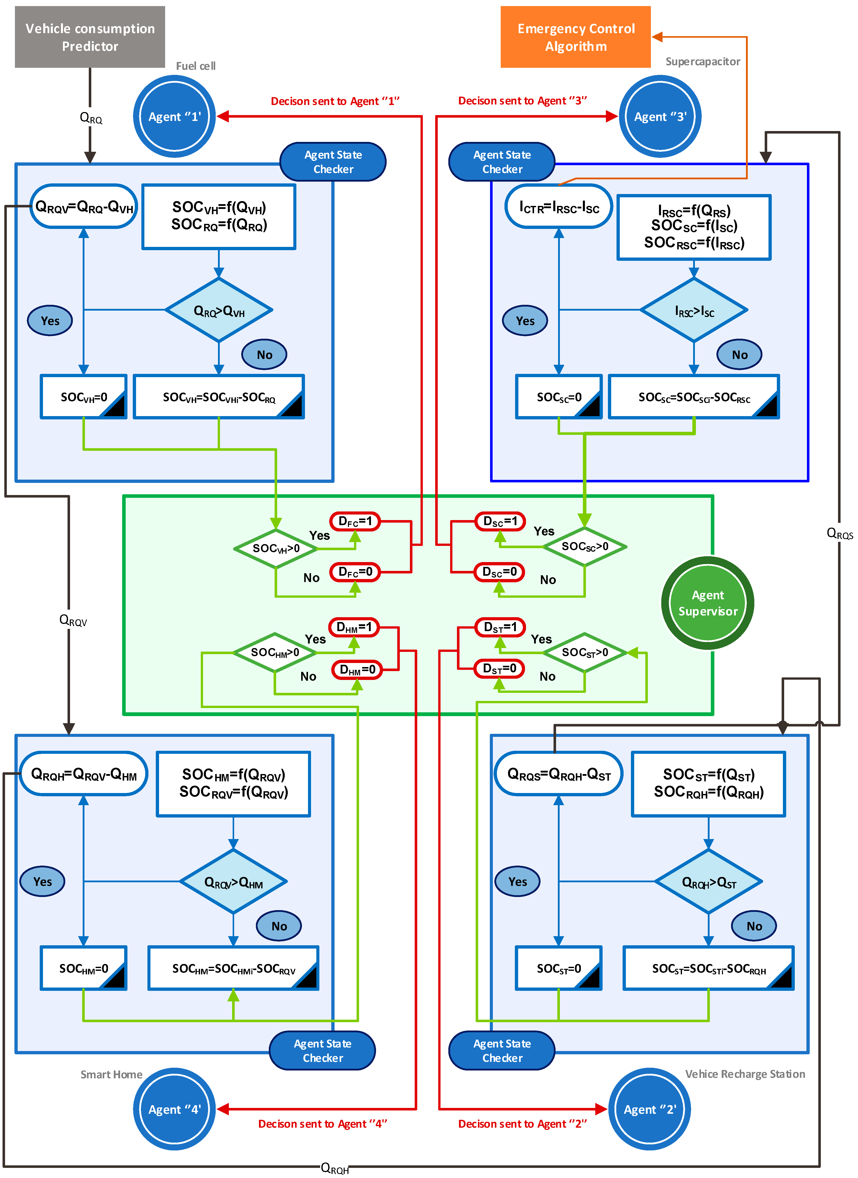
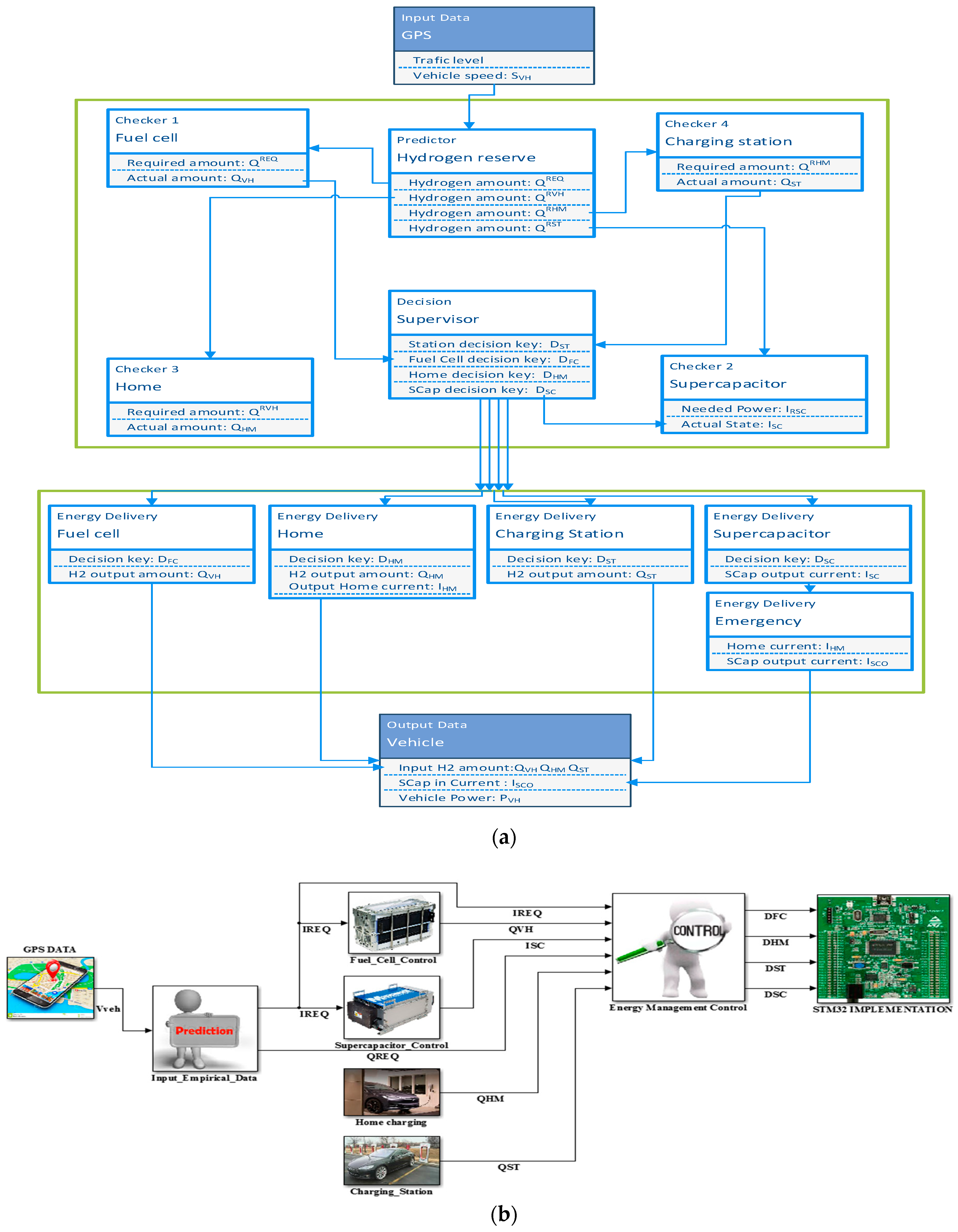
3. System Design
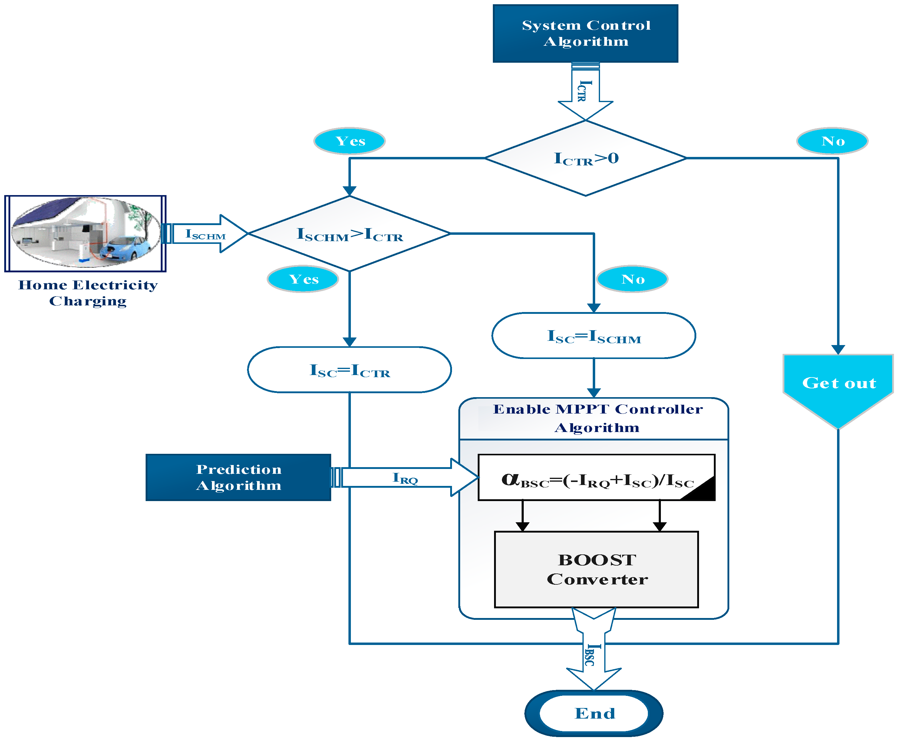
4. Energy Management Algorithms
4.1. General Principle
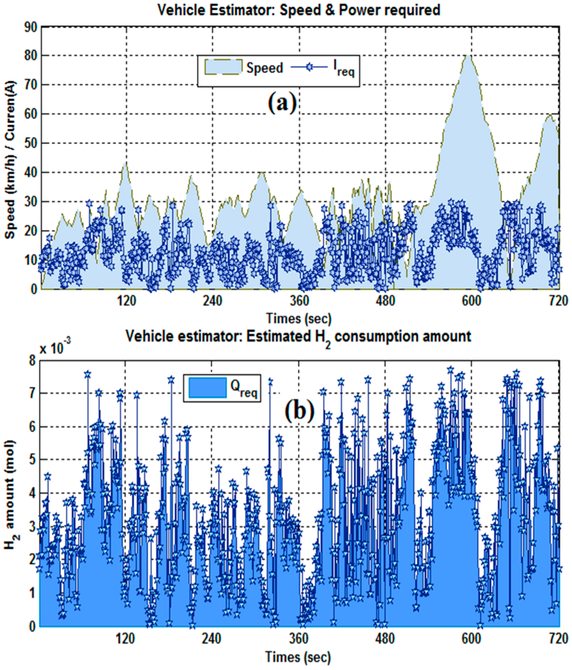
4.2. Simulation Process
5. Finding and Results
5.1. Simulation Test
5.2. Real-Time Simulation
6. Conclusions and Future Work
Author Contributions
Funding
Conflicts of Interest
Nomenclature
| QVH | Vehicle hydrogen fuel amount (mol) |
| NFC | PEMFC Stack number cells |
| IFC | PEMFC generated current (A) |
| ηFFC | PEMFC faraday efficiency (%) |
| QmaxVH | Maximum vehicle reserve amount (mol) |
| QmaxST | Maximum station reserve amount (mol) |
| QmaxHM | Maximum home reserve amount (mol) |
| QST | Charging station hydrogen fuel amount (mol) |
| QHM | Home reserve hydrogen fuel amount (mol) |
| QRQ | Required vehicle hydrogen fuel amount (mol) |
| QRQV | Required home hydrogen fuel amount (mol) |
| QRQH | Required station hydrogen fuel amount (mol) |
| PS | Storage hydrogen pressure (bar) |
| TS | Storage hydrogen temperature (°C) |
| VS | Storage hydrogen volume (L) |
| R | Constant real gas 8.31 J mol−1 K−1 |
| Tff | Traffic level |
| Preq | Required vehicle power (W) |
| QVH | Actual vehicle fuel reserve (mol) |
| QRQS | Remaining lack of hydrogen (mol) |
| Qreci | Required component “i” H2 amount (mol) |
| PR | Rolling power (W) |
| AV | Vehicle equivalent cross section (m2) |
| CR | Vehicle coefficient of rolling resistance |
| Vhev | Vehicle speed (km/h) |
| Ahev | Vehicle acceleration (m/s²) |
| ηM | Vehicle motor efficiency (%) |
| SOCSCi | Initial SC state of charge |
| SOCHMi | Initial home H2 state of charge |
| SOCVHi | Initial vehicle H2 state of charge |
| SOCSTi | Initial recharge station H2 state of charge |
| DFC | FC agent decision key |
| DSC | SC agent decision key |
| Ihome | Generated SC current via home reserve (A) |
| PA | Wheel power (W) |
| SOCVH | Vehicle hydrogen fuel state (%) |
| SOCSC | SC state of charge (%) |
| SOCST | Charging station state of charge (%) |
| SOCHM | Home state of charge (%) |
| αBSC | SC Boost duty cycle |
| ISC | SC Current (A) |
| ICTR | Control SC operating current (A) |
| ISCHM | SC Home reserve (A) |
| IRSC | Required SC current (A) |
| ISCmax | maximum SC operating current (A) |
| τdef | System deficit rate (%) |
| τrec | System recovery rate (%) |
| Vest | Estimated vehicle speed (km/h) |
| Vact | Actual vehicle speed (km/h) |
| Aact | Actual vehicle acceleration (m/s2) |
| Aprev | Previous vehicle acceleration value (km/h) |
| PL | Vehicle power (W) |
| PBK | Breaking vehicle power (W) |
| Qi | Gathered component “i” H2 amount (mol) |
| PAR | Viscous drag power (W) |
| PG | Slope effect power (W) |
| Mhev | Total vehicle mass (kg) |
| ρ | Air density (kg/m3) |
| CAR | Drag coefficient of the vehicle |
| ηGX | Gear efficiency (%) |
| ηinv | Vehicle inverter efficiency (%) |
| IFChome | Generated FC current by home H2 reserve (A) |
| SOCRQH | Expected Home H2 state of charge |
| SOCRQV | Expected vehicle H2 state of charge |
| SOCRQ | Expected H2 state of charge |
| SOCRS | Expected recharge station state of charge |
| DHM | Home agent decision key |
| DST | Recharge station agent decision key |
| IFCstation | Generated FC current by station H2 reserve (A) |
| V(max,min,moy) | Vehicle speed (Km/h) |
References
- Li, Q.; Yang, H.; Han, Y.; Li, M.; Chen, W. A state machine strategy based on droop control for an energy management system of PEMFC-battery-supercapacitor hybrid tramway. Int. J. Hydrog. Energy 2016, 41, 16148–16159. [Google Scholar] [CrossRef]
- Nasri, S.; Sami, B.S.; Cherif, A. Power management strategy for hybrid autonomous power system using hydrogen storage. Int. J. Hydrog. Energy 2016, 41, 857–865. [Google Scholar] [CrossRef]
- Nasri, S.; Ben Slama, S.; Yahyaoui, I.; Zafar, B.; Cherif, A. Autonomous hybrid system and coordinated intelligent management approach in power system operation and control using hydrogen storage. Int. J. Hydrog. Energy 2017, 42, 9511–9523. [Google Scholar] [CrossRef]
- Read, M.G.; Smith, R.A.; Pullen, K.R. Optimisation of flywheel energy storage systems with geared transmission for hybrid vehicles. Mech. Mach. Theory 2015, 87, 191–209. [Google Scholar] [CrossRef]
- Peña Alzola, R.; Sebastián, R.; Quesada, J.; Colmenar, A. Review of flywheel based energy storage systems. In Proceedings of the 2011 International Conference on Power Engineering, Energy and Electrical Drives, Malaga, Spain, 11–13 May 2011; pp. 1–6. [Google Scholar] [CrossRef]
- Karden, E.; Ploumen, S.; Fricke, B.; Miller, T.; Snyder, K. Energy storage devices for future hybrid electric vehicles. J. Power Sources 2007, 168, 2–11. [Google Scholar] [CrossRef]
- Emadi, A.; Young Joo, L.E.E.; Rajashekara, K. Power Electronics and Motor Drives in Electric, Hybrid Electric, and Plug-In Hybrid Electric Vehicles. IEEE Trans. Ind. Electron. 2008, 55, 2237–2245. [Google Scholar] [CrossRef]
- Ren, G.; Ma, G.; Cong, N. Review of electrical energy storage system for vehicular applications. Renew. Sustain. Energy Rev. 2015, 41, 225–236. [Google Scholar] [CrossRef]
- Vural, B.; Erdinc, O.; Uzunoglu, M. Parallel combination of FC and UC for vehicular power systems using a multi-input converter-based power interface. Energy Convers. Manag. 2010, 51, 2613–2622. [Google Scholar] [CrossRef]
- Ates, Y.; Erdinc, O.; Uzunoglu, M.; Vural, B. Energy management of an FC/UC hybrid vehicular power system using a combined neural network-wavelet transform based strategy. Int. J. Hydrog. Energy 2010, 35, 774–783. [Google Scholar] [CrossRef]
- Kabalo, M.; Paire, D.; Blunier, B.; Bouquain, D.; Simões, M.G.; Miraoui, A. Experimental validation of high-voltage-ratio low-input-current-ripple converters for hybrid fuel cell supercapacitor systems. IEEE Trans. Veh. Technol. 2012, 61, 3430–3440. [Google Scholar] [CrossRef]
- Iffouzar, K.; Amrouche, B.; Otmane Cherif, T.; Benkhoris, M.F.; Aouzellag, D.; Ghedamsi, K. Improved direct field oriented control of multiphase induction motor used in hybrid electric vehicle application. Int. J. Hydrog. Energy 2017, 42, 19296–19308. [Google Scholar] [CrossRef]
- Lin, B.M.; Suen, S.H.; Jang, J.S.C. Promotion strategy of electric scooters in Taiwan. World Electr. Veh. J. 2009, 3, 69–72. [Google Scholar] [CrossRef]
- Jin, J.; Crainic, T.G.; Løkketangen, A. A cooperative parallel metaheuristic for the capacitated vehicle routing problem. Comput. Oper. Res. 2014, 44, 33–41. [Google Scholar] [CrossRef]
- Crow, M.L. Economic scheduling of residential plug-in (hybrid) electric vehicle (PHEV) charging. Energies 2014, 7, 1876–1898. [Google Scholar] [CrossRef]
- Abdelhamid, M.; Pilla, S.; Singh, R.; Haque, I.; Filipi, Z. A comprehensive optimized model for on-board solar photovoltaic system for plug-in electric vehicles: Energy and economic impacts. Int. J. Energy Res. 2016, 40, 1489–1508. [Google Scholar] [CrossRef]
- Gao, L.; Winfield, Z.C. Life cycle assessment of environmental and economic impacts of advanced vehicles. Energies 2012, 5, 605–620. [Google Scholar] [CrossRef]
- Cano, M.H.; Kelouwani, S.; Agbossou, K.; Dubé, Y. Power management system for off-grid hydrogen production based on uncertainty. Int. J. Hydrog. Energy 2015, 40, 7260–7272. [Google Scholar] [CrossRef]
- Sciarretta, A.; Back, M.; Guzzella, L. Optimal control of parallel hybrid electric vehicles. IEEE Trans. Control Syst. Technol. 2004, 12, 352–363. [Google Scholar] [CrossRef]
- Offer, G.J.; Yufit, V.; Howey, D.A.; Wu, B.; Brandon, N.P. Module design and fault diagnosis in electric vehicle batteries. J. Power Sources 2012, 206, 383–392. [Google Scholar] [CrossRef]
- Lu, L.; Han, X.; Li, J.; Hua, J.; Ouyang, M. A review on the key issues for lithium-ion battery management in electric vehicles. J. Power Sources 2013, 226, 272–288. [Google Scholar] [CrossRef]
- Peterson, S.B.; Whitacre, J.F.; Apt, J. The economics of using plug-in hybrid electric vehicle battery packs for grid storage. J. Power Sources 2010, 195, 2377–2384. [Google Scholar] [CrossRef]
- Fotouhi, A.; Auger, D.J.; Propp, K.; Longo, S.; Wild, M. A review on electric vehicle battery modelling: From Lithium-ion toward Lithium-Sulphur. Renew. Sustain. Energy Rev. 2016, 56, 1008–1021. [Google Scholar] [CrossRef]
- Young, K.; Wang, C.; Wang, L.Y.; Strunz, K. Electric vehicle battery technologies. In Electric Vehicle Integration into Modern Power Networks; Springer: New York, NY, USA, 2013; pp. 15–56. [Google Scholar] [CrossRef]
- Thomas, C.E. Fuel cell and battery electric vehicles compared. Int. J. Hydrog. Energy 2009, 34, 6005–6020. [Google Scholar] [CrossRef]
- Konrad, K.; Markard, J.; Ruef, A.; Truffer, B. Strategic responses to fuel cell hype and disappointment. Technol. Forecast. Soc. Chang. 2012, 79, 1084–1098. [Google Scholar] [CrossRef]
- Sandy Thomas, C.E. Transportation options in a carbon-constrained world: Hybrids, plug-in hybrids, biofuels, fuel cell electric vehicles, and battery electric vehicles. Int. J. Hydrog. Energy 2009, 34, 9279–9296. [Google Scholar] [CrossRef]
- Yu, Z.; Zinger, D.; Bose, A. An innovative optimal power allocation strategy for fuel cell, battery and supercapacitor hybrid electric vehicle. J. Power Sources 2011, 196, 2351–2359. [Google Scholar] [CrossRef]
- Paladini, V.; Donateo, T.; de Risi, A.; Laforgia, D. Super-capacitors fuel-cell hybrid electric vehicle optimization and control strategy development. Energy Convers. Manag. 2007, 48, 3001–3008. [Google Scholar] [CrossRef]
- Boudoudouh, S.; Maâroufi, M. Real-time battery state of charge estimation in smart grid application by Multi Agent System. Int. J. Hydrog. Energy 2017, 42, 19487–19495. [Google Scholar] [CrossRef]
- García, P.; Torreglosa, J.P.; Fernández, L.M.; Jurado, F. Optimal energy management system for stand-alone wind turbine/photovoltaic/hydrogen/battery hybrid system with supervisory control based on fuzzy logic. Int. J. Hydrog. Energy 2013, 38, 14146–14158. [Google Scholar] [CrossRef]
- Tuohy, S.; Glavin, M.; Jones, E.; Hughes, C.; Kilmartin, L. Hybrid testbed for simulating in-vehicle automotive networks. Simul. Model. Pract. Theory 2016, 66, 193–211. [Google Scholar] [CrossRef]
- Sezen, S.; Karakas, E.; Yilmaz, K.; Ayaz, M. Finite element modeling and control of a high-power SRM for hybrid electric vehicle. Simul. Model. Pract. Theory 2016, 62, 49–67. [Google Scholar] [CrossRef]
- Zaouche, F.; Rekioua, D.; Gaubert, J.P.; Mokrani, Z. Supervision and control strategy for photovoltaic generators with battery storage. Int. J. Hydrog. Energy 2017, 42, 19536–19555. [Google Scholar] [CrossRef]
- Luta, D.N.; Raji, A.K. Decision-making between a grid extension and a rural renewable off-grid system with hydrogen generation. Int. J. Hydrog. Energy 2018, 43, 9535–9548. [Google Scholar] [CrossRef]
- Hemi, H.; Ghouili, J.; Cheriti, A. A real time fuzzy logic power management strategy for a fuel cell vehicle. Energy Convers. Manag. 2014, 80, 63–70. [Google Scholar] [CrossRef]
- Somkun, S.; Sirisamphanwong, C.; Sukchai, S. A DSP-based interleaved boost DC-DC converter for fuel cell applications. Int. J. Hydrog. Energy 2015, 40, 6391–6404. [Google Scholar] [CrossRef]
- Li, T.; Liu, H.; Zhao, D.; Wang, L. Design and analysis of a fuel cell supercapacitor hybrid construction vehicle. Int. J. Hydrog. Energy 2016, 41, 12307–12319. [Google Scholar] [CrossRef]
- Sulaiman, N.; Hannan, M.A.; Mohamed, A.; Ker, P.J.; Majlan, E.H.; Wan Daud, W.R. Optimization of energy management system for fuel-cell hybrid electric vehicles: Issues and recommendations. Appl. Energy 2018, 228, 2061–2079. [Google Scholar] [CrossRef]
- Zhang, Z.; Hu, C. System design and control strategy of the vehicles using hydrogen energy. Int. J. Hydrog. Energy 2014, 39, 12973–12979. [Google Scholar] [CrossRef]
- Sami, B.S.; Sihem, N.; Zafar, B.; Adnane, C. Performance study and efficiency improvement of Hybrid Electric System dedicated to transport application. Int. J. Hydrog. Energy 2017, 42, 12777–12789. [Google Scholar] [CrossRef]
- Thounthong, P.; Raël, S.; Davat, B. Energy management of fuel cell/battery/supercapacitor hybrid power source for vehicle applications. J. Power Sources 2009, 193, 376–385. [Google Scholar] [CrossRef]
- Zandi, M.; Payman, A.; Martin, J.; Pierfederici, S.; Davat, B.; Meibody-Tabar, F. Energy Management of a Fuel Cell/Supercapacitor/Battery Power Source for Electric Vehicular Applications. IEEE Trans. Veh. Technol. 2011, 60, 433–443. [Google Scholar] [CrossRef]
- Bigdeli, N. Optimal management of hybrid PV/fuel cell/battery power system: A comparison of optimal hybrid approaches. Renew. Sustain. Energy Rev. 2015, 42, 377–393. [Google Scholar] [CrossRef]
- Korsgaard, A.R.; Nielsen, M.P.; Kær, S.K. Part one: A novel model of HTPEM-based micro-combined heat and power fuel cell system. Int. J. Hydrog. Energy 2008, 33, 1909–1920. [Google Scholar] [CrossRef]
- Li, Q.; Chen, W.; Liu, Z.; Li, M.; Ma, L. Development of energy management system based on a power sharing strategy for a fuel cell-battery-supercapacitor hybrid tramway. J. Power Sources 2015, 279, 267–280. [Google Scholar] [CrossRef]
- Khayyam, H.; Bab-Hadiashar, A. Adaptive intelligent energy management system of plug-in hybrid electric vehicle. Energy 2014, 69, 319–335. [Google Scholar] [CrossRef]
- Shao, M.; Zhu, X.-J.; Cao, H.-F.; Shen, H.-F. An artificial neural network ensemble method for fault diagnosis of proton exchange membrane fuel cell system. Energy 2014, 67, 268–275. [Google Scholar] [CrossRef]
- Li, C.-H.; Zhu, X.-J.; Cao, G.-Y.; Sui, S.; Hu, M.-R. Dynamic modeling and sizing optimization of stand-alone photovoltaic power systems using hybrid energy storage technology. Renew. Energy 2009, 34, 815–826. [Google Scholar] [CrossRef]
- Hadartz, M.; Julander, M. Battery-Supercapacitor Energy Storage; Department of Energy and Environment Chalmers University of Technology: Göteborg, Sweden, 2008; Volume 74. [Google Scholar]
- Zhou, T.; Francois, B. Modeling and control design of hydrogen production process for an active hydrogen/wind hybrid power system. Int. J. Hydrog. Energy 2009, 34, 21–30. [Google Scholar] [CrossRef]


| Traffic Color Level | Decription | Speed Estimation | State | |
|---|---|---|---|---|
| Intense red traffic |  | Very heavy | V = 0 | Braking state |
| Red traffic |  | Heavy | V = Vmin | Low speed |
| Yellow traffic |  | Medium | V = Vmoy | Medium speed |
| Green traffic |  | Less | V = Vmax | Acceleration |
| Agents | Control Demand | Remaining Lack | Checked State |
|---|---|---|---|
| Agent “1” | QVH < QRQ | QRQV = QRQ − QVH | SOCVH = 0 |
| Agent “4” | QHM < QRQV | QRQH = QRQV − QHM | SOCHM = 0 |
| Agent “2” | QST < QRQH | IRS = f(QRQH − QST) | SOCST = 0 |
| Agent “3” | ISC < IRS | ICTR = IRS − ISC | SOCSC = 0 |
| State | Agent “1”: DFC | Agent “2”: DST | Agent “3”: DSC | Agent “4”: DHM |
|---|---|---|---|---|
| SOCVH > 0 | 1 | 0 | 0 | 0 |
| SOCHM > 0 | 1 | 0 | 0 | 1 |
| SOCST > 0 | 1 | 1 | 0 | 0 |
| SOCSC > 0 | 0 | 0 | 1 | 0 |
| Condition | Updated Parameter | Decision | Boost Control |
|---|---|---|---|
| ICTR < ISCHM | ISC = ISCHM | Regulate duty cycle | αBSC = (−IRQ − ISC)/ISC |
| ICTR < ISCHM | ISC = ICTR | System duty cycle |
| Components | Fuel Reserve (10−4 mol) | Required Fuel (10−4 mol) | Recovery Rate (%) |
|---|---|---|---|
| Vehicle | 6.84 | 32 | 21.38 |
| Home | 2.30 | 25 | 9.2 |
| Charging station | 10 | 26 | 38.47 |
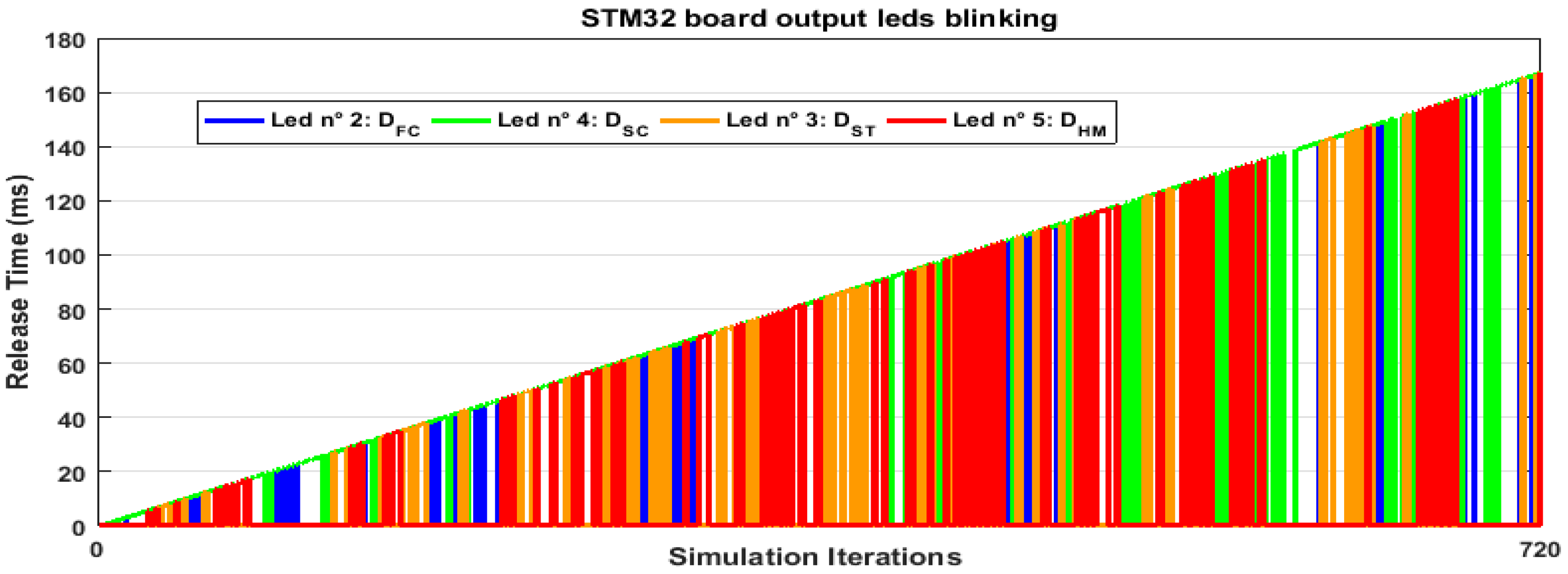
| STM32 Board Outputs | GPIO D Pin Number | Led Color | Mean Time Release (ms) | |
|---|---|---|---|---|
| Agent “1”: DFC | PIN 15: led 2 | Blue |  | 38.49 |
| Agent “2”: DST | PIN 13: led 3 | Orange |  | 11.54 |
| Agent”3”: DSC | PIN 12: led 4 | Green |  | 73.19 |
| Agent “4”: DHM | PIN 14: led 5 | Red |  | 14.30 |
© 2019 by the authors. Licensee MDPI, Basel, Switzerland. This article is an open access article distributed under the terms and conditions of the Creative Commons Attribution (CC BY) license (http://creativecommons.org/licenses/by/4.0/).
Share and Cite
Sami, B.; Sihem, N.; Gherairi, S.; Adnane, C. A Multi-Agent System for Smart Energy Management Devoted to Vehicle Applications: Realistic Dynamic Hybrid Electric System Using Hydrogen as a Fuel. Energies 2019, 12, 474. https://0-doi-org.brum.beds.ac.uk/10.3390/en12030474
Sami B, Sihem N, Gherairi S, Adnane C. A Multi-Agent System for Smart Energy Management Devoted to Vehicle Applications: Realistic Dynamic Hybrid Electric System Using Hydrogen as a Fuel. Energies. 2019; 12(3):474. https://0-doi-org.brum.beds.ac.uk/10.3390/en12030474
Chicago/Turabian StyleSami, Benslama, Nasri Sihem, Salsabil Gherairi, and Cherif Adnane. 2019. "A Multi-Agent System for Smart Energy Management Devoted to Vehicle Applications: Realistic Dynamic Hybrid Electric System Using Hydrogen as a Fuel" Energies 12, no. 3: 474. https://0-doi-org.brum.beds.ac.uk/10.3390/en12030474