Evaluation of Evaporative Emission and Feasibility of an Onboard Refueling Vapor Recovery System for Scooters


Department of Vehicle Engineering, National Formosa University, Yunlin 63201, Taiwan
*
Author to whom correspondence should be addressed.
Energies 2019, 12(4), 704; https://0-doi-org.brum.beds.ac.uk/10.3390/en12040704
Submission received: 18 December 2018
/
Revised: 13 February 2019
/
Accepted: 20 February 2019
/
Published: 21 February 2019
(This article belongs to the Special Issue Selected Papers from IEEE ICKII 2018)
Abstract
:This paper aims at the development of a novel onboard refueling vapor recovery (ORVR) system for scooters. The corresponding feasibility and evaporative emission are evaluated so that this preliminary study may offer important contributions for developing an effective ORVR system in Taiwan. A survey of research is initially conducted to compare the evaporative emission of the ORVR systems mounted on vehicles with that of the vapor recovery systems of Stage II installed at gas stations. The results show that the ORVR technology possesses better controllability and lower cost. Then, a novel ORVR system for scooters consisting of a self-made fuel tank, a self-made carbon canister, a vapor pipe, a fuel limit vent valve, and a surge protector etc. is developed and tested. The proposed self-made carbon canister possesses the storage capacity of fuel vapor large enough to perform the adsorption tests of diurnal and hot soak for as long as three consecutive days. Finally, the designed ORVR system is installed on a scooter and tested for evaporative emission under the regulation of Taiwan so as to check if it fulfills the requirements. The results are further compared with those with the evaporative emission control system (EVAP). A significant improvement on the leaking problem of fuel vapor is gained by using the proposed ORVR system. Consequently, the study can offer a valuable reference for developing an economical and effective ORVR system in the future.
1. Introduction
The ever-stringent emissions regulations as well as the introduction of fuel consumption regulations have aroused extensive striving toward enhancing automotive engine efficiencies for both diesel and gasoline engines [1]. The reduction of evaporative emission of fuel vapor has become one of the major issues. The fuel vapors released from traditional vehicles are mostly volatile organic compounds (VOCs) [2]. The equipment for improving environmental contamination caused by the evaporative emission of fuel vapor include the stage vapor recovery facilities placed at gas stations and onboard refueling vapor recovery (ORVR) systems incorporated in vehicles [3]. Some researches focused on comparative study between these two systems have been documented. Skelton et al. [4] evaluated the emissions of fuel vapor with Stage II controls only and ORVR requirements only respectively as shown in Figure 1. In the period when the production volume of oil was relatively low, the former was better than the latter. However, as the production volume of oil gradually increased, especially after 2010, utilizing ORVR has significantly gained advantages since the introduction of a control valve in the ORVR system, which has effectively recovered the evaporative emissions.
The research in the early stages mainly focused on the refueling vapor recovery at gas stations. In 2003, a test of refueling vapor recovery at the domestic gas stations with ten private cars or public transport was conducted in Mexico. The results show more than 80% of recovery efficiency [5]. In 2006, Kim et al. [6] proposed a simulation model about the adsorption and desorption dynamics in the ORVR system. The simulated results about effectiveness of adsorption and desorption were compared with the experimental data. The model was proven useful to design and fabricate an ORVR system adaptable to various climate and operation conditions. The research work of Hilpert et al. [7] reveals that the fuel spilled over during refueling at gas stations may be converted to ozone and causes air pollution, or it can be infiltrated into ground and results in severe contamination on soil and groundwater. The government of China has paid much attention to solving the air pollution problem of VOCs by using experimental tests, technical evaluation, emission model, strategic prediction, cost–effect analysis etc. The emission volume of VOCs released from the light gasoline vehicles in China is about 18.5 × 10³ tons in 2010, and estimated to reach 120 × 103 tons in 2040. Even if the system of Stage II controls is widely implemented, the corresponding fuel losses will still be around 40 × 103 tons in 2050. In contrast, the resulting evaporative emission by enforcing the installation of ORVR in new cars can be reduced by 97.5%. Accordingly, a solution of combing both Stage II controls and ORVR can be feasible to offer short-term and long-term benefits [8]. A research work in Japan shows that, by analyzing the evaporative emissions of eight commercially available gasoline cars during refueling process, the car equipped with ORVR emits alkanes for about 80% portion and alkenes for the remaining. However, C4 (four carbon chain molecules) alkenes have the largest impact on Maximum Incremental Reactivity (MIR). The researcher also estimated Ozone Formation Potential (OFP) and found out possible pollution sources using factor analysis [9].
For the purpose of reducing environmental pollution and energy consumption, recovering the fuel vapor emitted for the internal combustion engines using high-volatility gasoline is highly demanded in either non-refueling or refueling conditions [10]. To date, the government in Taiwan has enacted a regulation only for motorcycles and in non-refueling conditions, called Method and Procedure of Motorcycle Evaporative Emission Testing. Two methods for fuel vapor recovery are commonly applied. One is the implement of the ORVR system on vehicles used in non-refueling conditions, and the other is the installation of the vapor recovery systems at gas stations used during the refueling process. For the former method, the fuel vapor released from a fuel tank in a vehicle is inducted through a pipe and adsorbed by a carbon canister only when the vehicle is stationary, and then desorbed for recovery when the vehicle is started [11]. For the latter method, the fuel vapor emitted during refueling is induced back to the oil tank via a coaxial tube connected with the oil gun, depending on the ratio of the pumping capacity of fuel vapor and the refueling capacity of gasoline [5]. However, the recovery efficiency cannot be precisely measured. Moreover, the post-treatment at each gas station on the recycled fuel vapor cannot attain satisfactory benefits in view of energy utilization.
The advantages of ORVR may be listed as follows:
- The recovery efficiency can be kept steadily high, estimated about 98% per vehicle.
- The installation cost on vehicles is low, and the corresponding cost-performance ratio is high. Furthermore, comparatively low reconstruction cost invested in gas stations is required.
- The number of days for diurnal emission control can be increased from 1 to 3.
- In the long term, the system of ORVR can predominate over that of Stage II controls in view of emission control performance if the percentage of newly-made vehicles equipped with ORVR increases rapidly especially due to law enforcement imposed by domestic governments.
The disadvantages of ORVR may be summarized below:
- The ORVR system is only suitable for a built-in component fitted in new vehicles, rather than an aftermarket product adapted in used vehicles.
- Heavy vapor load may exceed the recovery capacity carbon canisters in practical application.
- A practical ORVR system scaled down for scooters has not been ready for market yet.
One of the vapor recovery methods used at gas stations is called Vapor Liquefied Capture System (VLCS) that consists of both Stage I and II recovery systems. The fuel vapor recycled back to the fuel tank at stage II is condensed and liquefied using an add-on equipment adapted at gas stations, and then carried back to oil depots via fuel tankers at stage I. Fung et al. [12] compared VLCS with the other two systems, i.e., Stage II and ORVR. The study shows that VLCS and ORVR possess the recovery rate of more than 95%, while Stage II merely has that of about 70%. Since VLCS and Stage II are implemented at gas stations, the promotion time for installing them at gas stations is shorter than that of adding ORVR to all the scooters on road. Furthermore, the recovery rates of VLCS and Stage II will decrease as the number of scooters equipped with ORVR increases. It is also concluded that ORVR is relatively low-cost and quite suitable for emission control.
The institution of environmental protection in the state of California has long been making world leading policies on air pollution prevention and control. Even so, ORVR systems are merely mandatorily adapted to some specific types of four-wheel cars in California, and the related researches are restricted to four-wheel cars rather than two-wheel vehicles. Therefore, this research can be one of the pioneer and innovative works of applying the ORVR systems specifically to two-wheel vehicles.
2. Design of the ORVR System
In this study, an ORVR system is designed to be adapted into a scooter that passes the domestic emission standard of 6th stage. The diurnal and hot-soak tests based on the Method and Procedure of Motorcycle Evaporative Emission Testing in Taiwan are carried out to measure the recovery mass of fuel vapor in grams. The major goal is to search for a more effective design of an EVAP fuel vapor recovery system for gaining the maximal benefit of energy utilization in industry.
The carbon canister of the proposed ORVR system is specially designed to possess an enhanced adsorption capacity of diurnal volatility of fuel vapor of 3 days, instead of 1 day in conventional specification. Furthermore, the fuel filling pipelines of fuel tank are specially designed to form a hydraulic seal so that the fuel vapor can be effectively induced into the carbon canister, rather than scattered to atmosphere through the fuel tank cap resulting in pollution. As for the design of the fuel tank, the fuel vapor emitted on the fuel level of the fuel tank during the refueling period, when the fuel tank cap is opened and the oil gun is inserted into the fuel tank, can be well preserved so that the source of undesirable leaking of fuel vapor can be restricted to the fuel surface in the pipelines.
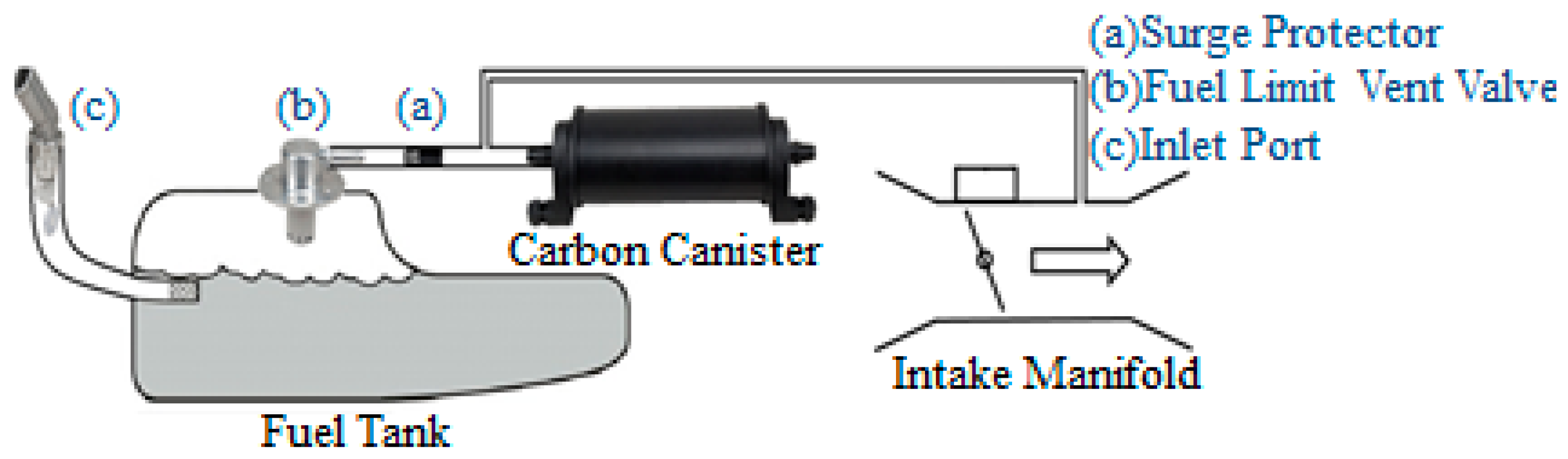
The design processes and related experimental tests for the ORVR system are briefly expressed by the flow chart shown in Figure 2. The schematic configuration of the ORVR system is shown in Figure 3, with its entire recovery operation is briefly described as follows. During refueling, the gradual increase in the volume of the liquid fuel in the fuel tank results in a compression effect on the fuel vapor contained in the fuel tank. Then, the fuel vapor is discharged from a blow vent through a fuel limit vent valve (FLVV) and a surge protector, and then injected into the carbon canister. Since liquid fuel flowing into the canister will cause permanent saturated failure, the FLVV and surge protector can prevent the injected liquid fuel from overflowing out of the tank and into the canister, as the fuel level is raised close to the top. The recovery process is completed once the refueling gun is cut off.
To deal with the severe problem of the permanent saturated failure of the canister resulting from intrusion by liquid fuel, the FLVV in this study is specially designed to fulfill the requirements of effective interception to surged inflow of liquid fluid as well as automatic cut-off when inclined, and the surge protector serves to provide minimal resistance to flow of gaseous fluid as liquid fluid is blocked. A surge protection mechanism when inclined is specifically adapted for two-wheeled vehicles, rather than four-wheeled vehicles, since the latter can inherently stand upright without worrying about inclination. When a two-wheeled scooter with a carbon canister falls to ground, a conventional fuel tank without a check valve will let liquid fuel pour down to the canister, causing irreversible damage. Therefore, a device capable of automatic cut-off and effective interception of overflow of liquid fuel is required in designing this ORVR system so as to keep the carbon canister in an optimal adsorption situation.
In this study, the components of the ORVR system fulfilling the above requirements including a self-made fuel tank, a self-made carbon canister, a vapor pipe, a fuel limit vent valve (FLVV), and a surge protector are first developed, and subsequently installed into a KYMCO scooter that meets the domestic emission standard of 6th stage. The performance tests of emission control are carried out and compared with those using Stage II vapor recovery system so as to evaluate the feasibility and benefit for scooter applications.
A small-scale refueling device satisfying the related standard about specifications of oil guns and oil flow is built in our laboratory to simulate the real refueling process at gas stations so that the designed specifications of the ORVR system can be well suitable for practical usage. The measuring devices include a precision measuring meter for fuel vapor, a portable leakage detector for fuel vapor, and an infrared thermometer. The materials used for the system cannot be the common types, but can be fuel, acid, and alkali resistant to ensure high sealability for the testing experiments. Moreover, the coordinated sets of safety measures for the testers should be thoroughly considered to minimize possibility of injury.
The detailed descriptions about designing the two key components of the ORVR system, i.e., the self-made fuel tank and the self-made carbon canister, are stated as follows. On the part of designing the self-made fuel tank, it is typically mended with reference to the original one. The schematic configuration of the original fuel tank is shown in Figure 4a. During refueling, the fuel vapor is inducted to the refueling port due to the pressure difference between the tank and atmosphere and scattered into the atmosphere. This causes major loss of fuel vapor. In the non-refueling period, the fuel vapor is redirected into the carbon canister for recycle. As for the designed fuel tank as shown in Figure 4b, as the oil gun is plugged into the port for refueling, the fuel vapor is prevented from flowing out of the refueling port by a check valve. Consequently, a further decrease of occupied space for fuel vapor while the fuel keeps flooding in will cause the vapor to be pushed into the canister through the FLVV. As the fuel level gradually reaches the top end during refueling, the FLVV will be shut off so as to prevent the liquid fuel from flowing into the canister, and then the fuel vapor keeps being vented out through a pressure relief valve until the refueling process stops so that undesirable splash will not occur while the oil gun is drawn out. In the non-refueling period, the fuel vapor generated in the fuel tank can be induced to the canister through the FLVV.
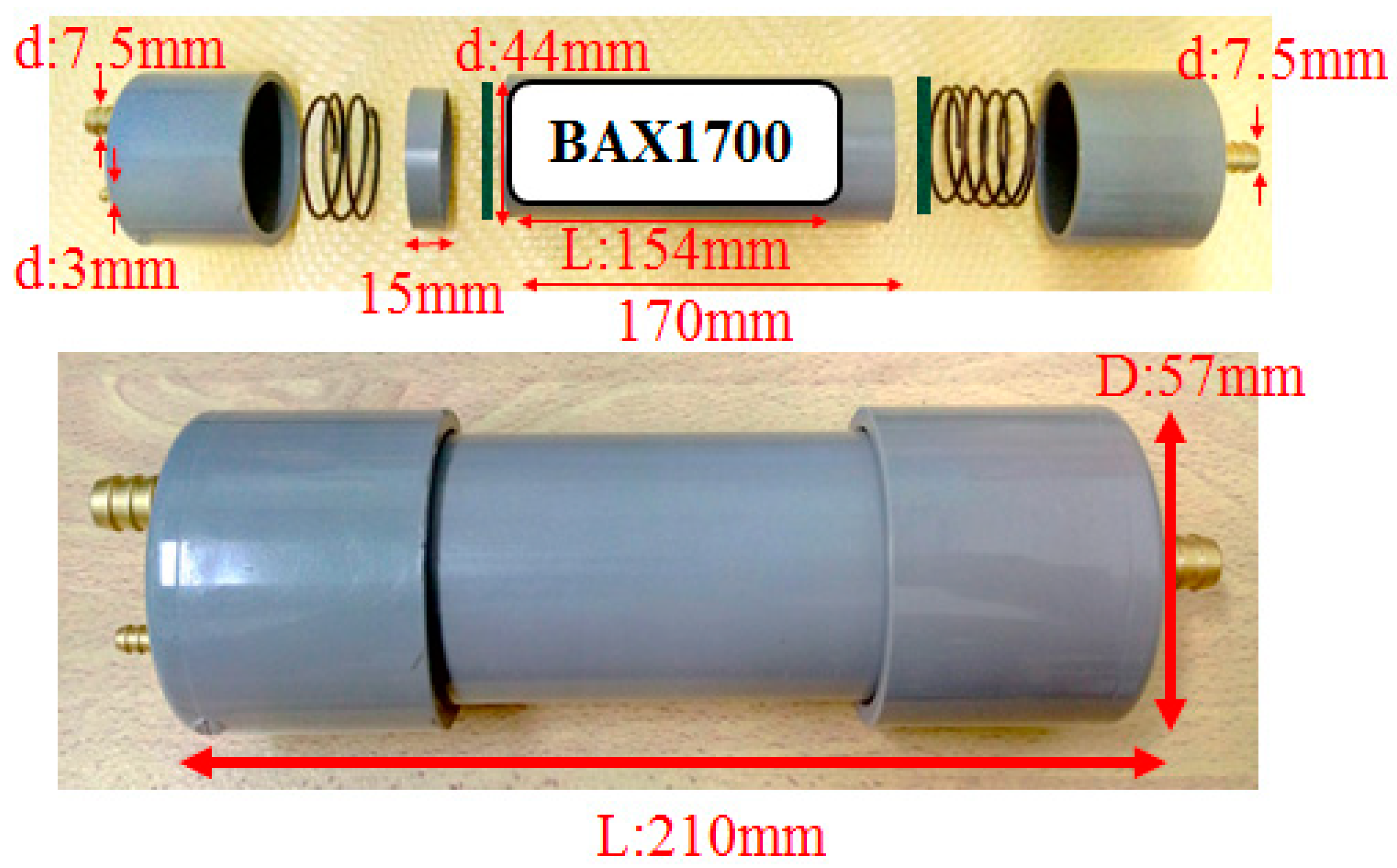
As for the self-made carbon canister, the major design goal is to increase the original capacity of diurnal adsorption from only one day to at least three days so as to fulfill the maximum adsorption performance according to the test requirements of diurnal evaporative emission for USA EPA (Environmental Protection Agency) as shown in Table 1. For this purpose, the structure of the canister should be redesigned, and the corresponding filling amount of carbon powder and volume aspect ratio are reevaluated. As a result, the canister is designed to contain spare space of 10–20 mm in length at the top and bottom. Two springs used to compress the carbon powder are placed on both the top and bottom of the canister. The value of volume aspect ratio, i.e., the ratio of length and diameter of the canister, is selected to be 3.5. Ingevity-BAX1700 carbon powder is recommended due to its excellent performance of adsorption and desorption. However, since no existing on-market ORVR system is available for scooters and limited space is used for installation, the preliminary design requirement for carbon powder should be modified to that of 80 g. As a result, the corresponding specifications and detailed dimensions for self-made carbon canister are expressed in Table 2 and Figure 5 respectively.
3. Evaporative Emission Test for the ORVR System
The main function of Evaporation Emission Control (EEC) is to collect the fuel vapor emitted from the fuel tank or carburetor, and temporarily store it in the carbon canister. As the engine turns on, the vacuum pressure generated in the intake system help draw the fuel vapor out of the canister and into the cylinders for combustion and producing available work. Since the major composition of fuel vapor is hydrocarbon (HC), enforcing ECC will be beneficial to reduce air pollution and fuel waste. Environmental regulation for evaporative emission in the United States began in the early 1970s and has been amended twice ever since. To date, the time for performing SHED (Sealed Housing for Evaporative Determination) test has increased to 72 h. The government of Taiwan followed United State and enacted an evaporative emission regulation in 1988, with the corresponding process flow chart of SHED test shown in Figure 6 [14]. The development processes for European Union and Japan are quite similar. Their evaporative emission control systems started in 1996 and 1998 respectively. California Air Resources Board of United States have performed several researches on evaporative emission. Accordingly, various test requirements of diurnal evaporative emission for different regions have been formulated and listed in Table 1. The diurnal evaporative emission rates measured under the specific test conditions of temperature and Reid vapor pressure are 1–4 g/h in United States of America, 0-3 in California, and 1–3 g/h in European Union and Taiwan [13].
4. Experimental Results
The designed carbon canister is first put into an adsorption test. Then, the entire assembled ORVR system including two key components, i.e., the designed carbon canister and the self-made fuel tank, is installed in a 125cc motorcycle available on the market to have an evaporative emission test. Since no precision and precious instruments available in our research environment to measure the absolute quantity of fuel vapor, a common smoke detector for measuring concentration of fuel vapor is used instead in this preliminary experiment. The resulting measured data can provide a valuable reference in the subsequent SHED tests. The experiment procedures and results are stated as follows.
4.1. Carbon Canister Adsorption Test
The schematic diagram of the carbon canister adsorption test is shown in Figure 7 and the corresponding testing procedures are described below:
- Purge the canister from fuel vapor by using an air compressor.
- Fill 2 L of gasoline into the tank A. By applying the law of connected vessels, the tank B is infused with the liquid gasoline with the same level as that of the tank A. Then keep them standing for 30 min so that the remaining space unoccupied by the liquid fuel in tank B is saturated with fuel vapor.
- Start to add 8 L of gasoline progressively at a steady rate into the tank A. Subsequently, the steadily rising fuel level of the tank B forces the fuel vapor to flow toward the designed canister. Meanwhile, the smoke detector is used to measure the variations of concentrations of fuel vapor at the venting in a fixed time interval so as to check whether the canister with the designated capacity would be inadequate or not.
The carbon canister adsorption tests following the above procedures are carried out three consecutive times with the initial time set at Step 3. The corresponding results of fuel vapor concentration vs. elapsed time are shown in Figure 8. The fuel vapor concentrations for the first test start to rise at about 90 s and continue the trend to the end of the test at 110 s. As for the subsequent two tests, their changing patterns are very similar. Both begin to increase at about 30 s and keep rising to the end of the tests. Additionally, both the measured values are higher than those of the first test, because a certain amount of the adsorbed fuel vapor in the first test cannot be purged completely at Step 1 and thus the available capacity of adsorption is lower for the subsequent two tests. However, the average value of concentrations for the three tests is less than 40% at the elapsed time of 90 s, far from an undesirable saturation condition according to the manufacture’s specification. This test procedure ensures that the designed components can offer a steady supply of fuel vapor for the ongoing adsorption tests. Therefore, the selected adsorption capacity of the designed canister is quite satisfactory for practical applications.
4.2. Motorcycle Evaporative Emission Test
After running the test for the adsorption test, the assembled ORVR system coupled with this designed canister and the self-made fuel tank is installed into a 125cc motorcycle to perform a motorcycle evaporative emission test. The tests are carried out two times. The corresponding results of diurnal and hot soak with an inclusion of the deterioration coefficient compared with the original motorcycle equipped with EVAP system are listed in Table 3. the results of the test, ORVR show a significant improvement of 26.9%. If only the results of diurnal and hot soak are considered with a deduction of the deterioration coefficient of 300 mg as listed in Table 4, a significant improvement of 67.25% reveals considerable potential for the proposed system.
5. Conclusions
In this study, a novel onboard refueling vapor recovery system for scooters, consisting of a self-made fuel tank, a self-made carbon canister, a vapor pipe, a fuel limit vent valve, and a surge protector etc., is designed and installed to a vehicle for testing. The major task is the development of the fuel tank and carbon canister for universal usage without considering the detailed design on the sealing between the refueling gun and port due to various fitting specifications in practice. Concerned with Venturi effect, the diameter of the pipe connected to the fuel tank and the carbon canister should be increased, and the length of the fuel vapor pipes need to be as short as possible, so that the fuel vapor can travel to the carbon canister in the shortest time for adsorption. Furthermore, the fuel tank opening should be situated as close to the bottom of the fuel tank as possible so that the liquid fuel filled in the lower portion of the tank can prevent the fuel vapor escaped from the refueling port. The designed capacity of the self-made carbon canister is proven sufficient through the adsorption test. Moreover, compared with the original motorcycle with EVAP system on the evaporative emission test, the testing motorcycle mounted with the proposed ORVR system gives a considerable improvement of 26.9% with the deterioration coefficient considered and that of 67.25% with a deduction of the deterioration coefficient.
Nowadays, neither an evaporative emission standard for ORVR systems nor a complete testing equipment costing several hundred thousand dollars are available in Taiwan. A comparative testing with a simple refueling equipment conducted in our laboratory has confirmed that, even without precision instruments for measuring the exact amount of fuel vapor, the measured amount of evaporative emission for ORVR are relatively low when compared with that for EVAP, and the fuel vapor can be effectively congregated and pushed toward the canister. Moreover, since no motorcycles equipped with any ORVR system nowadays are for sale in the global market, the corresponding special components are not available and the related assembling technologies are still under development. Therefore, the proposed novel ORVR system for scooters can offer valuable contributions for establishing mature technologies of evaporative emission control in the future. A subsequent confirmation testing is expected to be performed when the corresponding emission regulations and a standard testing equipment for motorcycles are ready in Taiwan.
Author Contributions
Conceptualization, C.-H.W.; Methodology, C.-H.W. and C.-T.C.; Software, C.-H.W. and W.-C.L.; Validation, C.-H.W., W.-C.L., and Y.-Y.L.; Formal Analysis, C.-H.W. and C.-T.C.; Investigation, Y.-Y.L.; Resources, C.-H.W. and W.-C.L.; Data Curation, C.-H.W.; Writing-Original Draft Preparation, C.-H.W. and W.-C.L.; Writing-Review & Editing, C.-T.C.; Visualization, W.-C.L., and Y.-Y.L.; Supervision, C.-T.C.; Project Administration, C.-H.W.; Funding Acquisition, C.-H.W.
Funding
The authors would like to thank the Ministry of Science and Technology of the Republic of China, Taiwan, for financial support for this research under Contract No. MOST 106-EPA-F-009-001 and 107-2221-E-150-036; and thanks to the Industrial Technology Research Institute (ITRI) project for advanced vehicle control.
Conflicts of Interest
The authors declare no conflict of interest.
References
- Alshammari, F.; Karvountzis-Kontakiotis, A.; Pesyridis, A.; Usman, M. Expander technologies for automotive engine organic rankine cycle applications. Energies 2018, 11, 1905. [Google Scholar] [CrossRef]
- Tibaquirá, J.E.; Huertas, J.I.; Ospina, S.; Quirama, L.F.; Niño, J.E. The effect of using ethanol-gasoline blends on the mechanical, energy and environmental performance of in-use vehicles. Energies 2018, 11, 221. [Google Scholar] [CrossRef]
- Shie, J.L.; Lu, C.Y.; Chang, C.Y.; Lee, D.J.; Chiu, C.Y.; Liu, S.P.; Chang, C.T. Recovery of gasoline vapor by a combined process of two-stage dehumidification and condensation. J. Chin. Inst. Chem. Eng. 2003, 34, 605–616. [Google Scholar]
- Skelton, E.; Rector, L. Onboard Refueling Vapor Recovery Systems Analysis of Widespread Use; NESCAUM Report; NESCAUM: Boston, MA, USA, 2007. [Google Scholar]
- Cruz-Núñez, X.; Hernández-Solís, J.M.; Ruiz-Suárez, L.G. Evaluation of vapor recovery systems efficiency and personal exposure in service stations in Mexico City. Sci. Total Environ. 2003, 309, 59–68. [Google Scholar] [CrossRef]
- Kim, D.K.; Kang, J.W.; Yang, D.R. Adsorption and desorption dynamics of evaporative fuel gas in canister of ORVR (On-Board Refueling Vapor Recovery) system. Stud. Surf. Sci. Catal. 2006, 159, 701–704. [Google Scholar]
- Hilpert, M.; Breysse, P.N. Infiltration and evaporation of small hydrocarbon spills at gas stations. J. Contam. Hydrol. 2014, 170, 39–52. [Google Scholar] [CrossRef] [PubMed]
- Yang, X.; Liu, H.; Cui, H.; Man, H.; Fu, M.; Hao, J.; He, K. Vehicular volatile organic compounds losses due to refueling and diurnal process in China: 2010–2050. J. Environ. Sci. 2015, 33, 88–96. [Google Scholar] [CrossRef] [PubMed]
- Yamada, H.; Inomata, S.; Tanimotoc, H. Refueling emissions from cars in Japan: Compositions, temperature dependence and effect of vapor liquefied collection system. Atmos. Environ. 2015, 120, 455–462. [Google Scholar] [CrossRef]
- Jeon, J.; Lee, S.; Park, S. Effect of the fuelling strategy on the combustion and emission characteristics of a gasoline-diesel dual-fuel engine. Proc. Inst. Mech. Eng. Part D J. Automob. Eng. 2017, 231, 310–321. [Google Scholar] [CrossRef]
- Yamada, H.; Inomata, S.; Tanimoto, H.; Hata, H.; Tonokura, K. Estimation of refueling emissions based on theoretical model and effects of E10 fuel on refueling and evaporative emissions from gasoline cars. Sci. Total Environ. 2018, 622–623, 467–473. [Google Scholar] [CrossRef] [PubMed]
- Fung, F.; Maxwell, B. Onboard Refueling Vapor Recovery: Evaluation of the ORVR Program in the United States; Working Paper; The International Council on Clean Transportation: Washington, DC, USA, 2011. [Google Scholar]
- Guo, X.N.; Huang, T.Z.; Zhuang, X.H.; Weng, W.Y. Discussion on evaporative pollution control systems in major countries. Chin. J. Veh. Ind. 2007, 157, 67–73. [Google Scholar]
- Motorcycle Evaporative Emission Testing Methods and Procedures. Available online: https://oaout.epa.gov.tw/law/LawContent.aspx?id=GL005999 (accessed on 20 September 2018).
Figure 1.
Comparisons of evaporative emissions between onboard refueling vapor recovery (ORVR) and Stage II controls [4].
Figure 1.
Comparisons of evaporative emissions between onboard refueling vapor recovery (ORVR) and Stage II controls [4].

Figure 2.
The flow chart of design process and experimental test for the ORVR system for scooters.

Figure 3.
The schematic configuration of the designed ORVR.

Figure 4.
Schematic configuration for (a) the original fuel tank and (b) the designed fuel tank.

Figure 5.
Exploded view of the self-made carbon canister.

Figure 6.
Process flow chart of SHED (Sealed Housing for Evaporative Determination) test in Taiwan [13].
Figure 6.
Process flow chart of SHED (Sealed Housing for Evaporative Determination) test in Taiwan [13].

Figure 7.
Schematic diagram of the test bench for the carbon canister adsorption test.

Figure 8.
Results of fuel vapor concentration vs. elapsed time for the carbon canister adsorption test.
Figure 8.
Results of fuel vapor concentration vs. elapsed time for the carbon canister adsorption test.


Table 1.
Test requirements of evaporative emission control (EVAP) in different regions [13].
Table 1.
Test requirements of evaporative emission control (EVAP) in different regions [13].
| Region | Diurnal | (Hot Soak) | (Running Loss) | Reid Vapor Pressures | |
|---|---|---|---|---|---|
| USA | EPA | 22.2–35.6 °C (72 h) | 32.2–37.8 °C (1 h) | UDDS+NYCC+UDDS (72 min) | 8.7–9.2 psi |
| CARB | 18.3–40.6 °C (72 h) | 37.8–43.3 °C (1 h) | UDDS+NYCC+UDDS (72 min) | 6.7–7.0 psi | |
| EU/Japan | 20–35 °C (24 h) | 23–31 °C (1 h) | --- | 8.12–8.7 psi (56–60 kPa) | |
| Taiwan | 16–30 °C (1 h) | 20–30 °C (1 h) | --- | 8.12–9.3psi (0.56–0.64 bar) | |
Table 2.
Comparisons of carbon canister specifications.
| Item | Original Canister | Designed Canister |
|---|---|---|
| Volume Aspect Ratio | 1.73 | 3.5 |
| Weight of Carbon Powder (g) | 44.3 | 80 |
| The Maximum Length (mm) | 102.5 | 210 |
| Maximum Radius (mm) | 52 | 57 |
| Total Weight (g) | 78.69 | 357.38 |
Table 3.
Evaporative emission test results of EVAP and ORVR (Onboard Refueling Vapor Recovery) systems (1).
Table 3.
Evaporative emission test results of EVAP and ORVR (Onboard Refueling Vapor Recovery) systems (1).
| Type | Diurnal Standards | Hot Soak Standards | Deterioration Coefficient | Test Results | Improvement Compared to EVAP |
|---|---|---|---|---|---|
| EVAP | 136 | 64 | 300 | 500 | -- |
| ORVR | 31.8 | 33.7 | 300 | 365.5 | 26.9% |
# 6th motorcycle evaporative emission standard: Diurnal + Hot soak + Deterioration Coefficient 300 mg < 2000 mg.
Table 4.
Evaporative emission test results of EVAP and ORVR systems (2).
| Type | Diurnal Standards | Hot Soak Standards | Test Results | Improvement Compared to EVAP |
|---|---|---|---|---|
| EVAP | 136 | 64 | 200 | -- |
| ORVR | 31.8 | 33.7 | 65.5 | 67.25% |
© 2019 by the authors. Licensee MDPI, Basel, Switzerland. This article is an open access article distributed under the terms and conditions of the Creative Commons Attribution (CC BY) license (http://creativecommons.org/licenses/by/4.0/).
Share and Cite
MDPI and ACS Style
Wu, C.-H.; Chung, C.-T.; Lin, W.-C.; Lin, Y.-Y. Evaluation of Evaporative Emission and Feasibility of an Onboard Refueling Vapor Recovery System for Scooters. Energies 2019, 12, 704. https://0-doi-org.brum.beds.ac.uk/10.3390/en12040704
AMA Style
Wu C-H, Chung C-T, Lin W-C, Lin Y-Y. Evaluation of Evaporative Emission and Feasibility of an Onboard Refueling Vapor Recovery System for Scooters. Energies. 2019; 12(4):704. https://0-doi-org.brum.beds.ac.uk/10.3390/en12040704
Chicago/Turabian StyleWu, Chien-Hsun, Cheng-Ta Chung, Wei-Chen Lin, and You-Ya Lin. 2019. "Evaluation of Evaporative Emission and Feasibility of an Onboard Refueling Vapor Recovery System for Scooters" Energies 12, no. 4: 704. https://0-doi-org.brum.beds.ac.uk/10.3390/en12040704
Note that from the first issue of 2016, this journal uses article numbers instead of page numbers. See further details here.