Article

Improved Frequency Locked Loop Based Synchronization Method for Three-Phase Grid-Connected Inverter under Unbalanced and Distorted Grid Conditions

Department of Electric Power, South China University of Technology, Guangzhou 510640, China
*
Author to whom correspondence should be addressed.
Submission received: 15 February 2019 / Revised: 10 March 2019 / Accepted: 11 March 2019 / Published: 15 March 2019
(This article belongs to the Section F: Electrical Engineering)

Abstract

:
To quickly and accurately estimate the parameters of the fundamental positive- and negative-sequence under the unbalanced and distorted grid voltage, a synchronization method is presented in this paper. The proposed method is based on both a harmonic decoupling network consisting of multiple dual second-order generalized integrators (MDSOGIs) and an improved frequency locked loop (IFLL), so it is called the MDSOGI-IFLL. Due to the IFLL, the system has the feature that the dynamic performance of estimating the fundamental frequency is independent of the variation of both the fundamental positive- and negative-sequence voltage. In this paper, a first-order linear frequency adaption model is established for the design of the IFLL. Finally, the good performance of the proposed MDSOGI-IFLL is validated by the simulation and experiment.

1. Introduction

The grid voltage parameters, such as frequency, phase angle, and amplitude, are important information for ensuring the stable operation of grid-connected inverters [1,2]. The most widely used synchronization technique is the synchronous rotating frame PLL (SRF-PLL) [3,4,5]. The SRF-PLL, designed with a high bandwidth, can detect information from the grid voltage quickly and accurately in ideal cases. Under the conditions that there are low order harmonics on the grid voltage, the bandwidth of the SRF-PLL needs to be reduced to maintain a high detection accuracy. Nevertheless, the reduction in the bandwidth will result in a reduction in its response speed. A method like this will not be an acceptable solution under the unbalanced grid. So some advanced methods have been proposed to solve this problem. A decoupled double synchronous reference-frame PLL (DDSRF-PLL) is proposed by Rodriguez et al. [6], which can estimate the fundamental positive- and negative-sequence accurately by means of the double synchronous rotation transformation. The main drawback of the DDSRF-PLL is that its transient response is highly influenced by the phase-angle jumps of the input signal [7]. In 2002, a positive sequence filter is designed by Yuan et al. to detect the fundamental positive sequence from the unbalanced and distorted grid voltage [8]. Several synchronization methods, such as the software PLL-based fast PLL [9], the inverse park transformation-based PLL [10,11], the second order generalized integrator based PLL (SOGI-PLL) [11,12,13] and the SOGI-based frequency locked loop (SOGI-FLL) [14,15,16], have been proposed for the similar purpose. Because of the second-order low-pass or band-pass filtering characteristics, these aforementioned methods can work well when there are little low-order harmonics on the distorted grid voltage. However, just like the studies proven in [14,17], the influence caused by the low-order harmonics cannot be completely eliminated through the second-order filter.
Therefore, to improve the immunity to the low-order harmonics, the adaptive or notch filtering algorithm-based synchronization methods have been presented in [18,19]; the repetitive and multi-resonant controllers based schemes were proposed in [20]; and solutions based on moving average filters were suggested in [21,22]. As demonstrated in [23], for the methods based on the moving average filters, the introduction of filtering algorithm will increase the system delay, thus reducing the dynamic response speed. Thanks to the use of an FLL, an interesting synchronization technique with frequency adaptive capability is shown in [24]. Unlike the way of reducing the bandwidth, the scheme is based on a cross-feedback network consisting of multiple dual second-order generalized integrators. So it can accurately extract the fundamental positive- and negative-sequence while maintaining a satisfactory dynamic response speed even when the low-order harmonics are relatively large. However, the major drawback of the scheme is that the transient performance of detecting the grid voltage fundamental frequency is susceptible to influence by the fundamental negative sequence.
This paper aims to address the aforementioned issue of the synchronization method presented in [24]. Thus, an improved FLL is proposed to improve the dynamic performance of estimating the grid fundamental frequency under the unbalanced grid voltage. Due to the fundamental negative sequence voltage being taken into account in the design of the FLL unit, the IFLL has the feature that its dynamic performance is independent of the variation of both the fundamental positive and negative sequence voltage. Accordingly, a new synchronization technique based on the MDSOGI-IFLL is proposed for three-phase grid-connected inverter under unbalanced and distorted grid conditions in this paper.
This paper is organized as follows. According to [24], Section 2 presents a brief introduction of the small-signal modeling of the SOGI-FLL. In Section 3, the dynamic characteristics of the DSOGI-FLL are analyzed in detail, which is not carried out in [24]. Based on the analysis, the DSOGI-IFLL is proposed and a first-order linear frequency adaption model is established for the design of the IFLL. Then, the application of the DSOGI-IFLL for the three-phase system under unbalanced and distorted grid voltage is demonstrated in Section 4. Finally, the detailed simulation and experiment dynamic performance comparison between the proposed MDSOGI-IFLL and other synchronization methods is shown in Section 5. Finally, this paper concludes in Section 6.

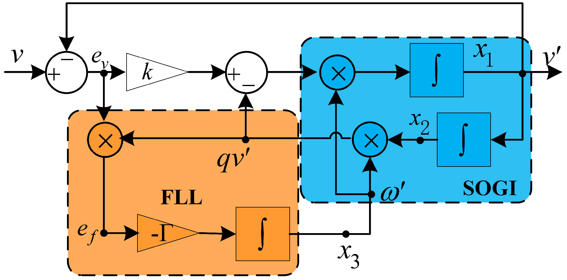
2. Modeling Analysis of the SOGI-FLL

The structure of the SOGI-FLL is shown in Figure 1 [24], including the SOGI and a standard FLL, where ω is the resonance frequency and the two output signals of the SOGI-FLL are v and q v .
From Figure 1, the space-state equations of the SOGI-FLL are given by
x ˙ = x ˙ 1 x ˙ 2 = Ax + B v = - k ω ω 2 1 0 x 1 x 2 + k ω 0 v
y = v q v = Cx = 1 0 0 ω x 1 x 2
where x in (1) is the state vector, and y in (2) is the output vector. In addition, the dynamic response of the FLL is described by
ω ˙ = Γ x 2 ω v x 1
As it can be appreciated from (3), the dynamical response of the SOGI-FLL depends on four parameters, namely: the amplitude and frequency of the input signal and the values of k and Γ .
Considering the steady-state, there is
ω ˙ = 0 ω = ω 0
Then (1) gives rise to
x ¯ ˙ ω ˙ = 0 = x ¯ ˙ 1 x ¯ ˙ 2 = A x ¯ 1 x ¯ 2 = 0 ω 2 1 0 x ¯ 1 x ¯ 2
in which the steady-state variables are written with a bar over them.
The eigenvalues of the matrix A in (5) have a null real part, so the steady-state outputs of the system response in a periodic orbit at the ω frequency. Therefore, for a given sinusoidal input signal v = V sin ( ω 0 t + φ ) , the output vector will be given by
y v = V sin ω 0 t + φ = v q v = V sin ω 0 t + φ cos ω 0 t + φ
When the resonant frequency ω of SOGI-FLL is set to a constant which is not equal to the input signal frequency, then the output vector would still keep in a stable orbit defined by
y = v q v = V D j ω 0 sin ω 0 t + φ + D j ω 0 ω ω 0 cos ω 0 t + φ + D j ω 0
where
D j ω 0 = k ω 0 ω k ω 0 ω 2 + ω 0 2 ω 2 2 D j ω 0 = arctan ω 2 ω 0 2 k ω 0 ω
It is possible to appreciate from (7) that the SOGI states keep the following steady-state relationship when a sinusoidal input signal at the frequency ω 0 is applied to its input, even if ω ω 0
x ˙ 1 = ω 0 2 x 2
Therefore, the error signal e v in Figure 1 can be obtained from (1) as
e v = v x 1 = 1 k ω x ˙ 1 + ω 2 x 2
According to (9) and (10), the steady-state frequency error signal e f in Figure 1 is given by
e f = x 2 ω e v = x 2 2 k ω 2 ω 0 2
When the system approaches steady-state, it can be assumed that ω ω 0 . In such a case, ω 2 ω 0 2 can be approximated as
ω 2 ω 0 2 2 ω ω 0 ω
Then the dynamics of the whole system can be described as
ω ˙ = Γ e f = Γ k x 2 2 ω 2 ω 2 2 Γ k x 2 2 ω ω 0 ω
For an input signal v = V sin ω 0 t + φ , the square of x 2 will be given by
x 2 2 = V 2 2 ω 0 2 D j ω 0 2 1 + cos 2 ω t + φ + D j ω 0
In steady-state, D ( j ω 0 ) is approximated to 1 in (14). Ignoring the AC component in x 2 , then (13) can be simplified to
ω ˙ = Γ V 2 k ω ω ω 0

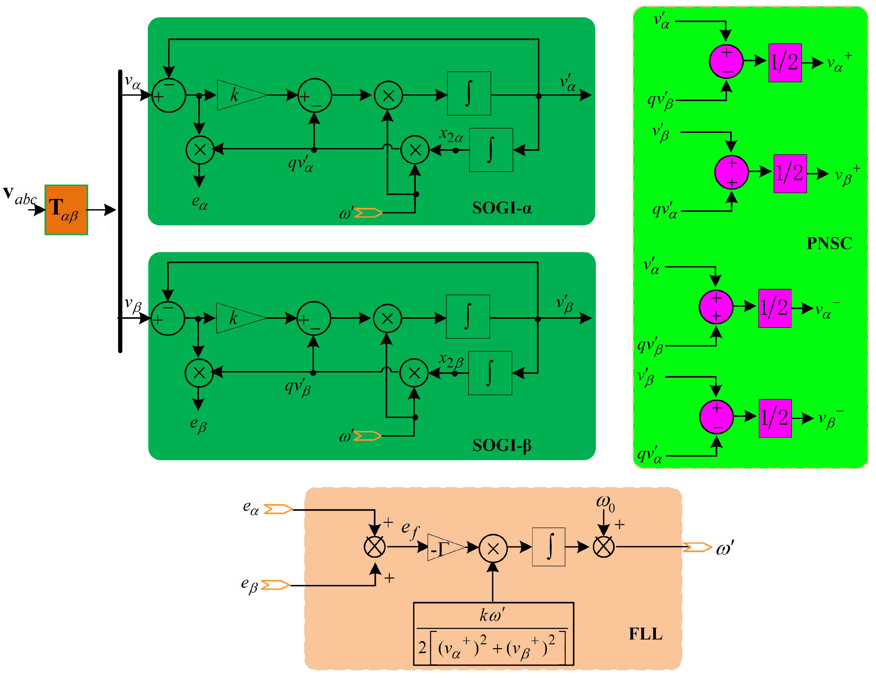
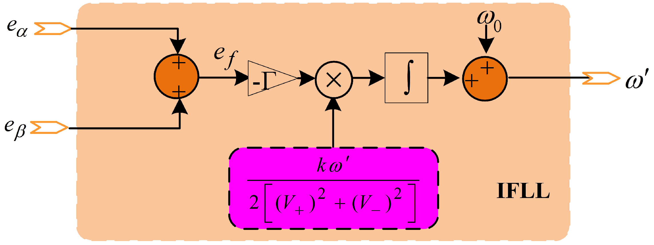
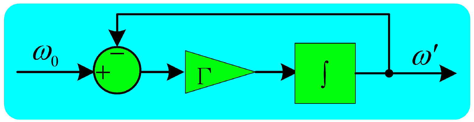
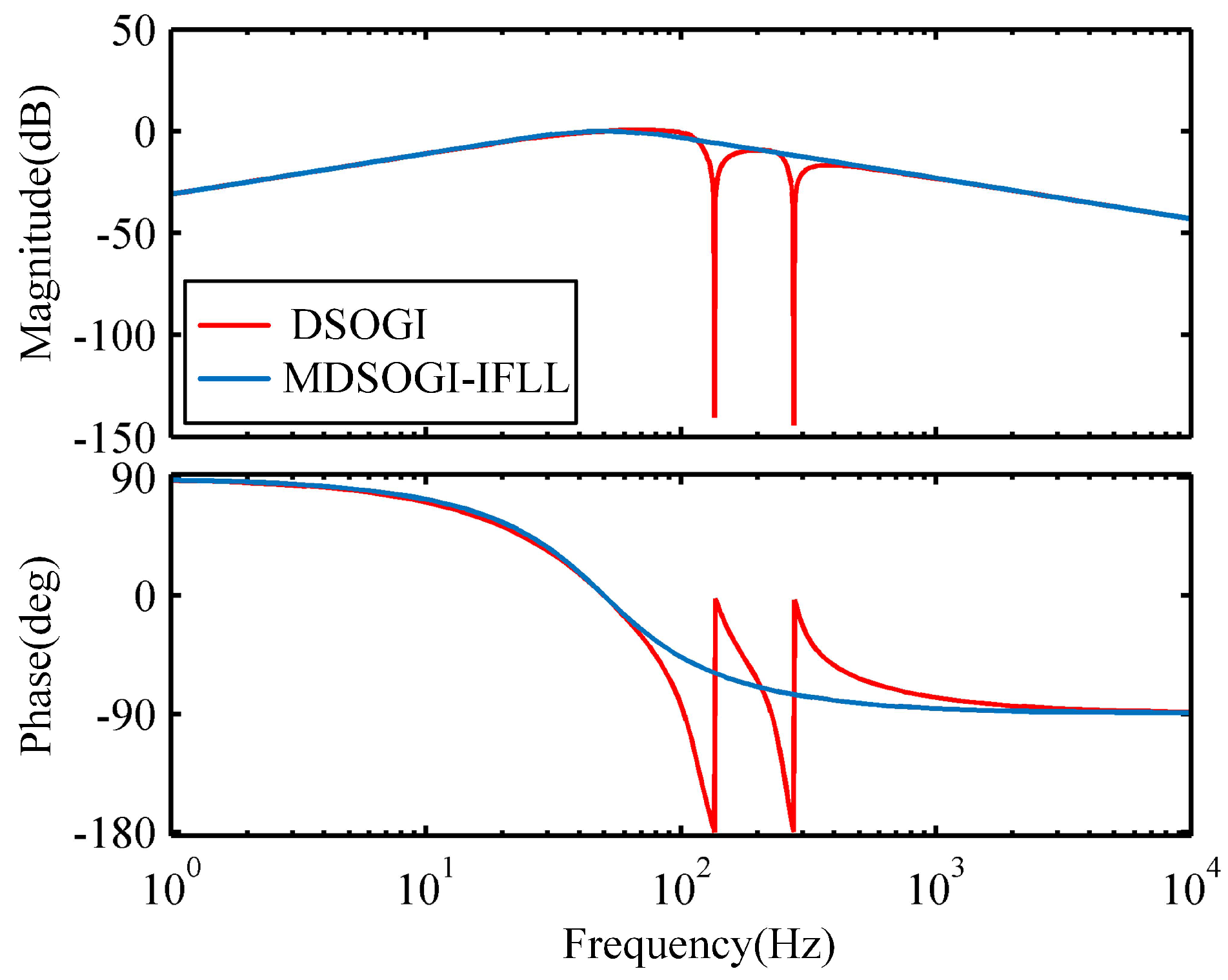
3. Dynamics Analysis of the DSOGI-FLL and Its Improved Design

The structure of the DSOGI-FLL discussed in [24] is shown in Figure 2, which is used for three-phase grid-connected inverter system.
In the system of Figure 2, two SOGIs working on the α β stationary reference frame provide the input signals to a positive-/negative-sequence calculation block (PNSC), which is able to detect the positive- and negative-sequence components of a three-phase input vector at a certain frequency ω 0 . The two signals, v α + and v β + , are the fundamental positive-sequence in the α β coordinate. According to the analysis in Section 2, the two steady-state signals in Figure 2, i.e., e α and e β , are given by
e α = ω x 2 α ( v α v α ) e β = ω x 2 β ( v β v β )
Thus, the steady-state frequency error signal e f in DSOGI-FLL can be calculated by
e f = e α + e β = x 2 α 2 + x 2 β 2 k ( ω 2 ω 0 2 )
Then, according to the design of FLL shown in Figure 2, the dynamics of the DSOGI-FLL can be described as
ω ˙ Γ ω ( x 2 α 2 + x 2 β 2 ) ω 2 ω 0 2 2 [ ( v α + ) 2 + ( v β + ) 2 ]
Considering ω 2 ω 0 2 can be approximated as 2 ω ω 0 ω in the steady-state, then (18) gives rise to
ω ˙ Γ ω 2 ( x 2 α 2 + x 2 β 2 ) ω ω 0 ( v α + ) 2 + ( v β + ) 2
Under the unbalanced and distorted grid voltage conditions, the input signals, v α and v β , contain not only the fundamental positive-sequence voltage but also fundamental negative-sequence voltage and harmonic components. The harmonic components can be eliminated by the method described in the next section, so only the negative-sequence is considered in the following analysis in this section. Therefore, the input signals can be described as
v α = V + cos ( ω 0 t ) + V cos ( ω 0 t φ ) v β = V + sin ( ω 0 t ) V sin ( ω 0 t φ )
where V + and V are the amplitude of the positive-and negative-sequence voltage, respectively, and φ is the phase angle of the negative-sequence.
From (20), the square of x 2 α and x 2 β in the steady-state will be given by
x 2 α 2 = 1 ω 2 ( V + 2 sin 2 θ + + V 2 sin 2 θ + 2 V + V sin θ + sin θ ) x 2 β 2 = 1 ω 2 ( V + 2 cos 2 θ + + V 2 cos 2 θ 2 V + V cos θ + cos θ )
in which θ + = ω 0 t , θ = ω 0 t φ . From (19) and (21), it can be concluded
ω ˙ Γ ( v α + ) 2 + ( v β + ) 2 V + 2 ω ω 0 V + 2 + V 2 2 V + V cos ( θ + + θ )
According to the average theory introduced in [25,26], (22) can be simplified to
ω ˙ Γ V + 2 ω ω 0 ( V + 2 + V 2 ) = Γ ω ω 0 1 + V V + 2
The value of V V V + V + in (23) is commonly defined as the voltage unbalance factor. From (23), it can be concluded that the design of FLL shown in Figure 2 cannot make the dynamics of the DSOGI-FLL independent of the voltage fluctuation under the unbalanced grid condition ( V 2 0 ). To address the issue, an improved FLL is proposed in this paper, as shown in Figure 3.
In this way, the dynamics of the DSOGI-IFLL gives rise to
ω ˙ Γ V + 2 + V 2 ω ω 0 ( V + 2 + V 2 ) Γ ω ω 0
From (24), it can be concluded that the dynamics of the DSOGI-IFLL is neither nondependent on the fundamental positive sequence nor the fundamental negative sequence. Then, the whole system can be described as the first-order linear system shown in Figure 4.
The transfer function of the system in Figure 4 is given by
ω ω 0 s = Γ s + Γ
Therefore, the settle time is exclusively dependent on the parameter Γ and can be approximated by
t s 4.6 Γ
It should be pointed out that the establishment of (26) needs to consider the settle time relationship between the IFLL and the SOGI. When the gain k is set to 2 , the settle time of SOGI, defined as t s o g i , should meet the inequality that t s 2 t s o g i . According to Figure 1, the transfer functions of the SOGI are given by
D s = v v s = k ω s s 2 + k ω s + ω 2
Q s = q v v s = k ω 2 s 2 + k ω s + ω 2
For a given input signal v = V sin ω 0 t , it can be concluded from (27) and (28) that
v = 1 1 ( k k 2 2 ) 2 sin ( 1 ( k k 2 2 ) 2 ω 0 t ) e k ω 0 t k ω 0 t 2 2 + V sin ω 0 t q v = 1 1 ( k k 2 2 ) 2 cos ( 1 ( k k 2 2 ) 2 ω 0 t φ ) e k ω 0 t k ω 0 t 2 2 V cos ω 0 t
then, the settle time t s o g i can be estimated by
t s o g i = 9.2 k ω 0

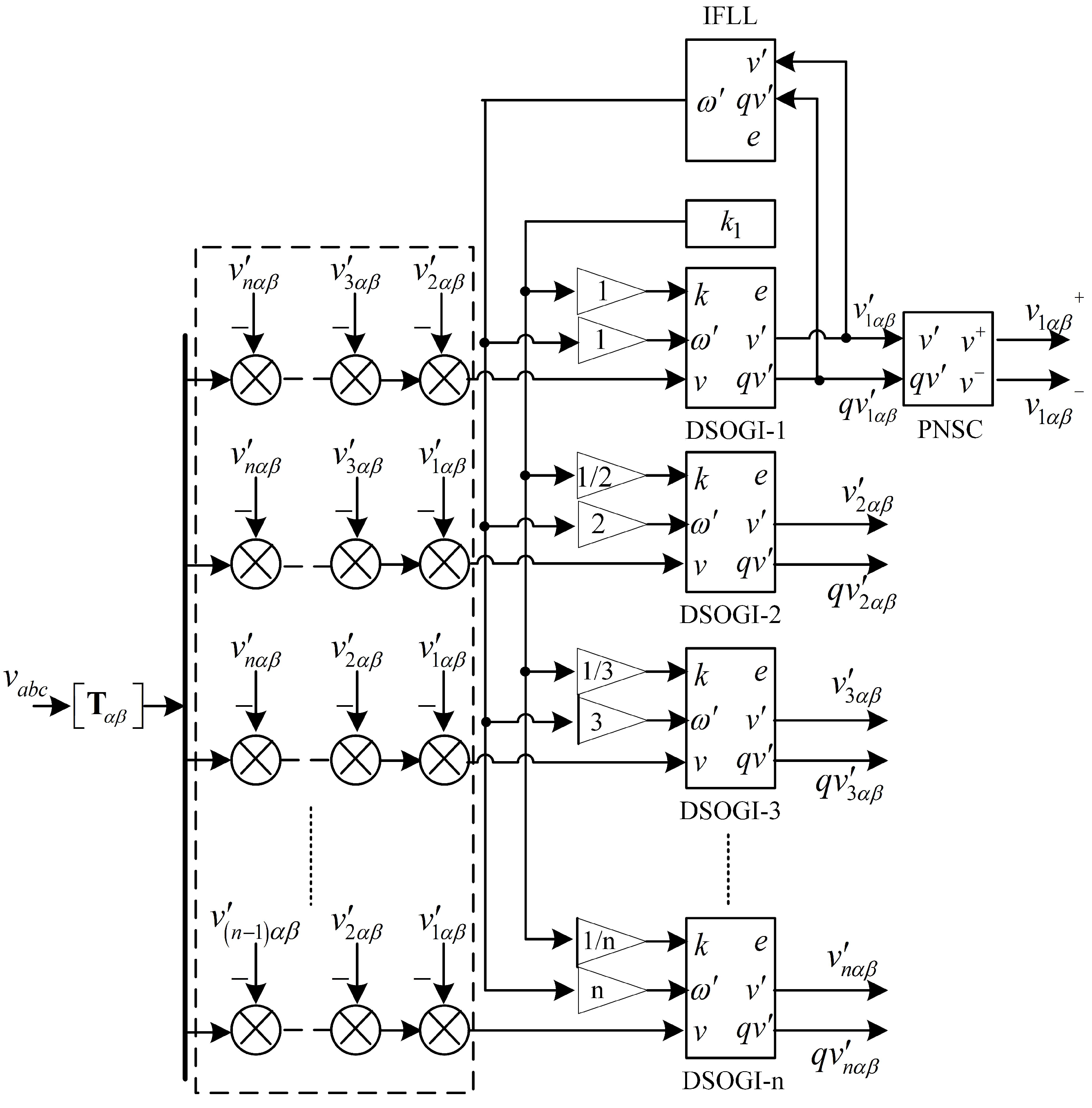
4. Synchronization Method Based on Multiple DSOGI-IFLL

The DSOGI-IFLL can perfectly reject the high-order harmonics due to its second-order filtering characteristics. However, the detection error will not be acceptable when the low-order grid voltage harmonics, such as the third and fifth harmonics, are relatively large. To address this issue, a cross-feedback network, proposed in [24], consisting of multiple DSOGIs, like the one shown in Figure 2, tuned at different frequencies, is presented as an effective solution to accurately detect the information of the fundamental sequence, even under the extremely distorted grid voltage. From now on, this new system will be referred as multiple DSOGI-IFLL (MDSOGI-IFLL). The main building block of the MDSOGI-IFLL consisted of n DSOGIs is shown in Figure 5.
From Figure 5, the transfer function of the fundamental sequence for the output is given by
v 1 v s = D 1 s j = 2 n 1 D i s 1 D 1 s D i s
where i is the harmonic order for the DSOGI-i block, and D i s is the general expression for the output v i , which is given by
D i s = i k i ω s s 2 + i k i ω s + i ω 2
As an example, Figure 6 shows the bode diagram of an MDSOGI-IFLL with three DSOGIs tuned at first, third, and fifth harmonics.
As shown in Figure 6, the designed cross-feedback network exhibits notch characteristics at third and fifth harmonics. Consequently, the synchronization method based on an MDSOGI-IFLL, tuned at the interesting harmonics, can accurately detect the information of the fundamental sequence, even under the extremely distorted grid voltage.

5. Simulations and Experiments

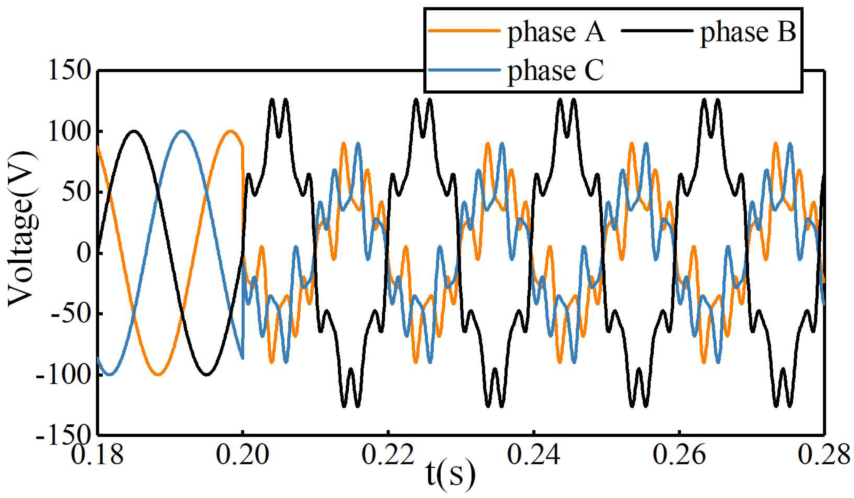
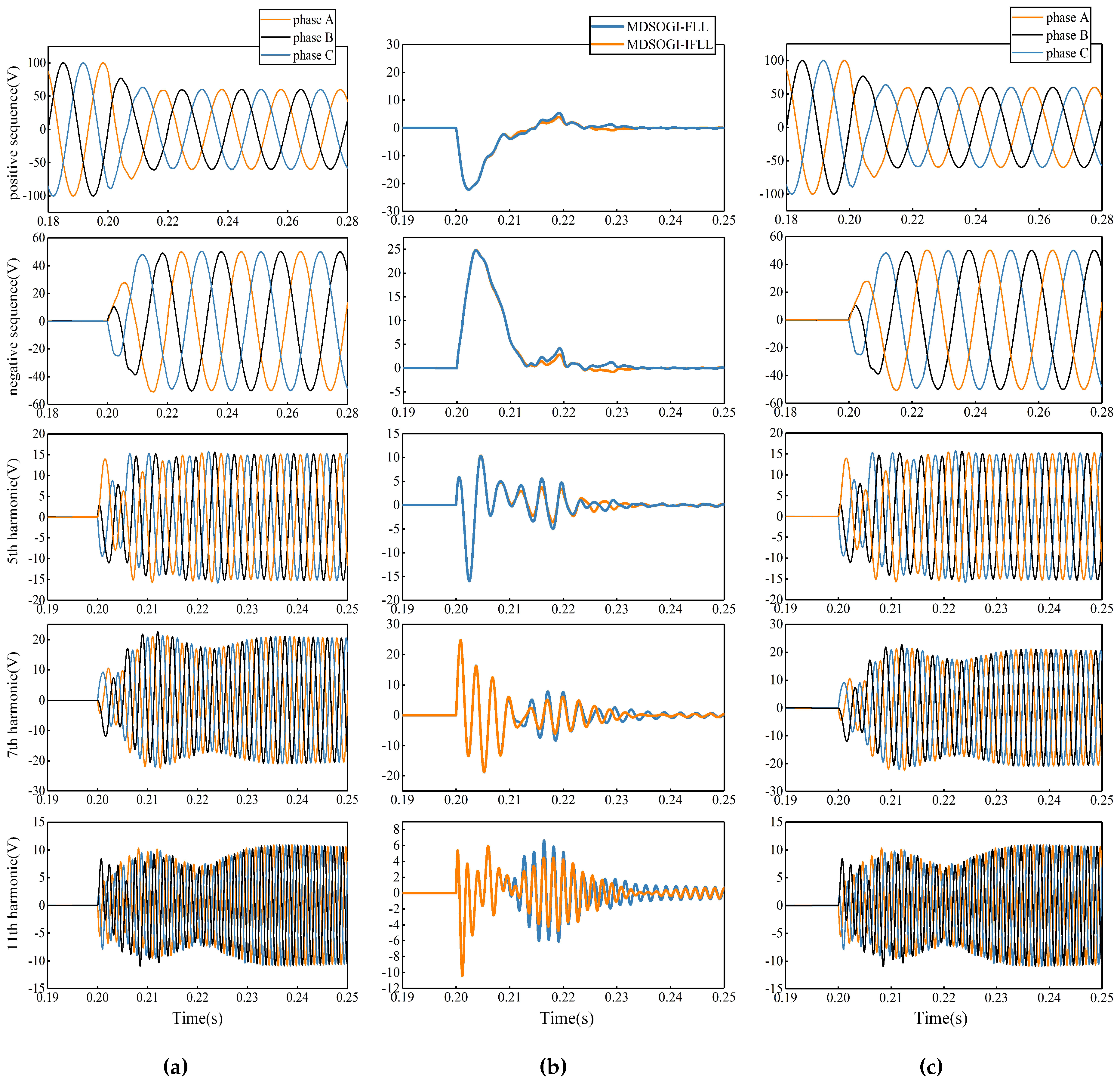
5.1. Harmonic Detection Simulation Test

Simulations have been carried out to demonstrate the good performance of the MDSOGI-IFLL. In the simulations, the gain for the fundamental sequence, i.e., DSOGI-1, was set to 2 . To maintain the same bandwidth, the gain for the other DSOGIs was divided by the harmonic order ( k 1 = 2 ). In addition, the gain for the IFLL was set to Γ = 100 . Both the MDSOGI-FLL and the MDSOGI-IFLL consisted of four DSOGIs tuned at first, fifth, seventh, eleventh harmonics.
Initial parameters are as follows: the amplitude and frequency of the ideal grid voltage were set to 100 V and 50 Hz respectively. At 0.2 s, the values of the fundamental positive-sequence and negative-sequence were set to 0.6 and 0.5 p.u. As for harmonics, the fifth, seventh, and eleventh harmonics were set to 0.15, 0.2, and 0.1 p.u., respectively. Furthermore, the fundamental frequency was changed to 50.5 Hz. The grid voltage considered in the simulation is shown in Figure 7.
The simulation results are shown in Figure 8 and Figure 9. It should be noticed that the plots in Figure 9, from top to bottom, are for the fundamental positive- and negative-sequence, fifth, seventh, and eleventh harmonics.
As shown in Figure 8, during the transient process, the two FLLs show almost the same time response in 0.2 s to 0.21 s. However, after that stage, the maximum dynamic frequency detection error for MDSOGI-FLL is 16.68 rad/s, and for MDSOGI-IFLL, that is 9.78 rad/s, almost half of the former. So it can be appreciated from Figure 8 that the MDSOGI-IFLL has better dynamic performance. It can be concluded from Figure 8 that both the MDSOGI-FLL and the MDSOGI-IFLL can accurately detect the fundamental grid frequency in the steady state. However, the estimated frequency of the MDSOGI-IFLL has a smaller ripple.
Figure 9 shows the excellent performance of the MDSOGI-IFLL of detecting the instantaneous components for the fundamental sequence and those harmonics even under the extremely unbalanced and distorted grid voltage. In view of the converging speed of the tracking error, the MDSOGI-IFLL behaves as good as the MDSOGI-FLL, even better.

5.2. Experimental Verification

Experiments have been carried out to further validate the effectiveness of the proposed synchronization method. An uninterruptible power supply device based on the floating-point 150 MHz TMS320F28335 DSP is used to generate the required grid voltage. In addition, the programs of the synchronization methods mentioned in this part, such as the DDSRF-PLL and the MDSOGI-FLL, were implemented in the same type DSP. All important data were stored in the DSP. In addition, the data used for graphing were derived through the XDS510 emulator. The input signals, i.e., the grid voltage, are obtained by sampling.
The second order integrator [27] is used for the digital implementation of the synchronization algorithms. In this way, the integrator is approximated by
T s 2 3 z 1 z 2 1 z 1
where T s is the sample period (100 μs in this paper).

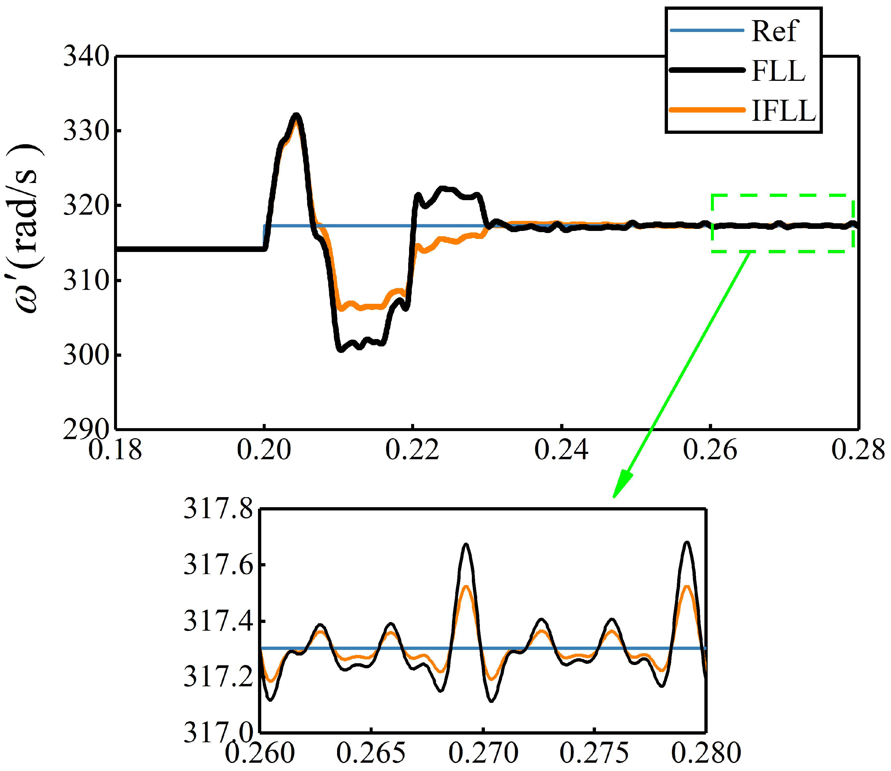
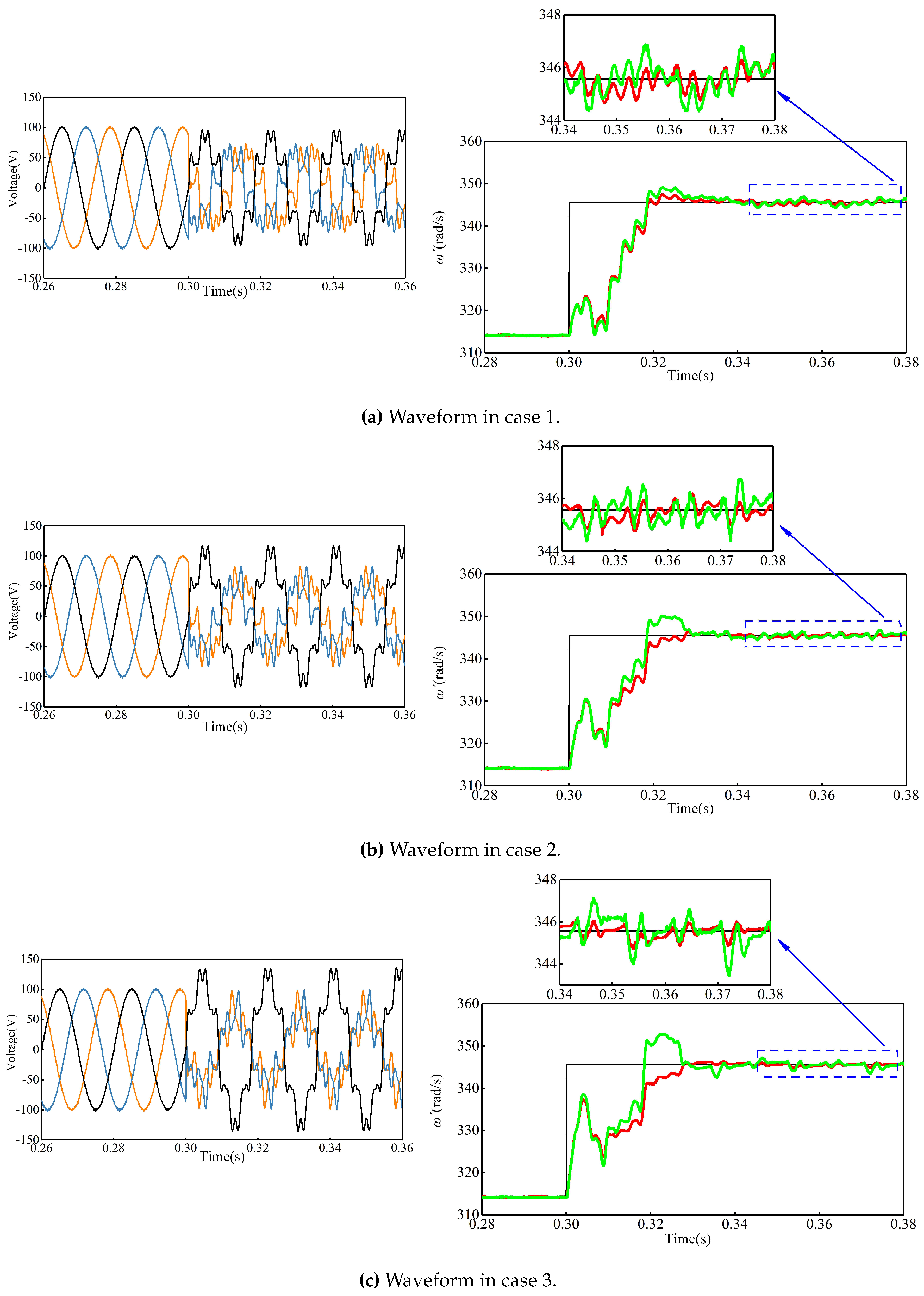
5.2.1. Performance Comparison of Frequency Detection between MDSOGI-FLL and MDSOGI-IFLL

In this paper, the transient frequency detection performance comparison between the MDSOGI-FLL and the proposed MDSOGI-IFLL under unbalanced grid voltage is mainly concerned. So the inter-harmonics discussed in [24] were not in consideration. Three cases, shown in Table 1, were set to make an all-around comparison of the two synchronization methods. The nominal amplitude and frequency of the grid voltage were set to 100 V (1 p.u.) and 50 Hz respectively. During the grid fault, the fundamental frequency was changed to 55 Hz.
The waveforms of grid voltage considered in the experiment and the fundamental frequency estimated by the MDSOGI-FLL and the MDSOGI-IFLL are shown in Figure 10.
From Figure 10, it’s obvious that the overshoot of the MDSOGI-FLL is getting bigger and bigger as the increasing of the value of the fundamental negative sequence, which confirms the theoretical analysis in Section 3. However, the MDSOGI-IFLL can accurately detect the grid frequency nearly without overshooting in each case. Moreover, the MDSOGI-IFLL has a smaller ripple in the steady state. According to these experiment results, it can be concluded that the MDSOGI-IFLL has a better transient performance than the MDSOGI-FLL while having high detection accuracy.

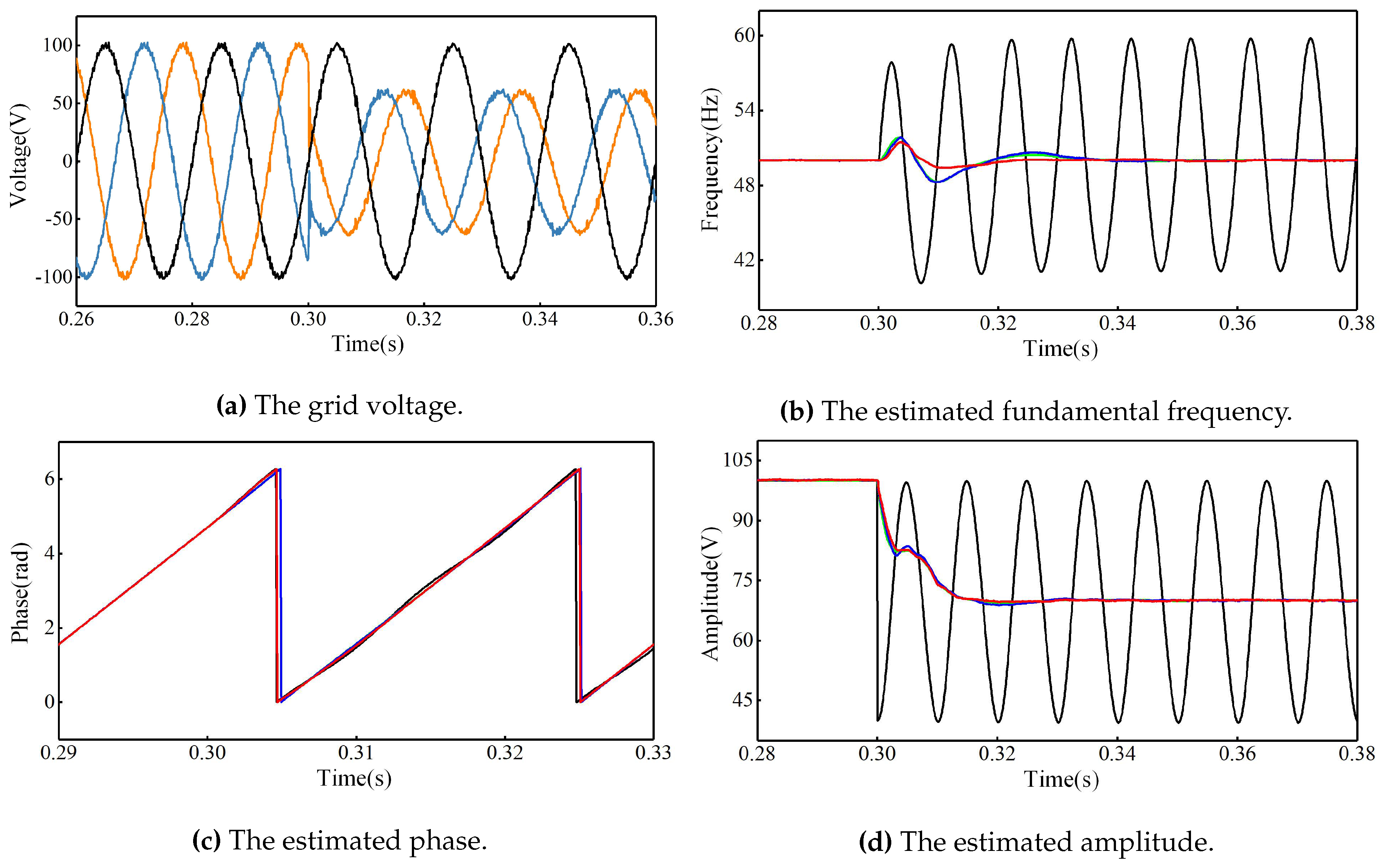
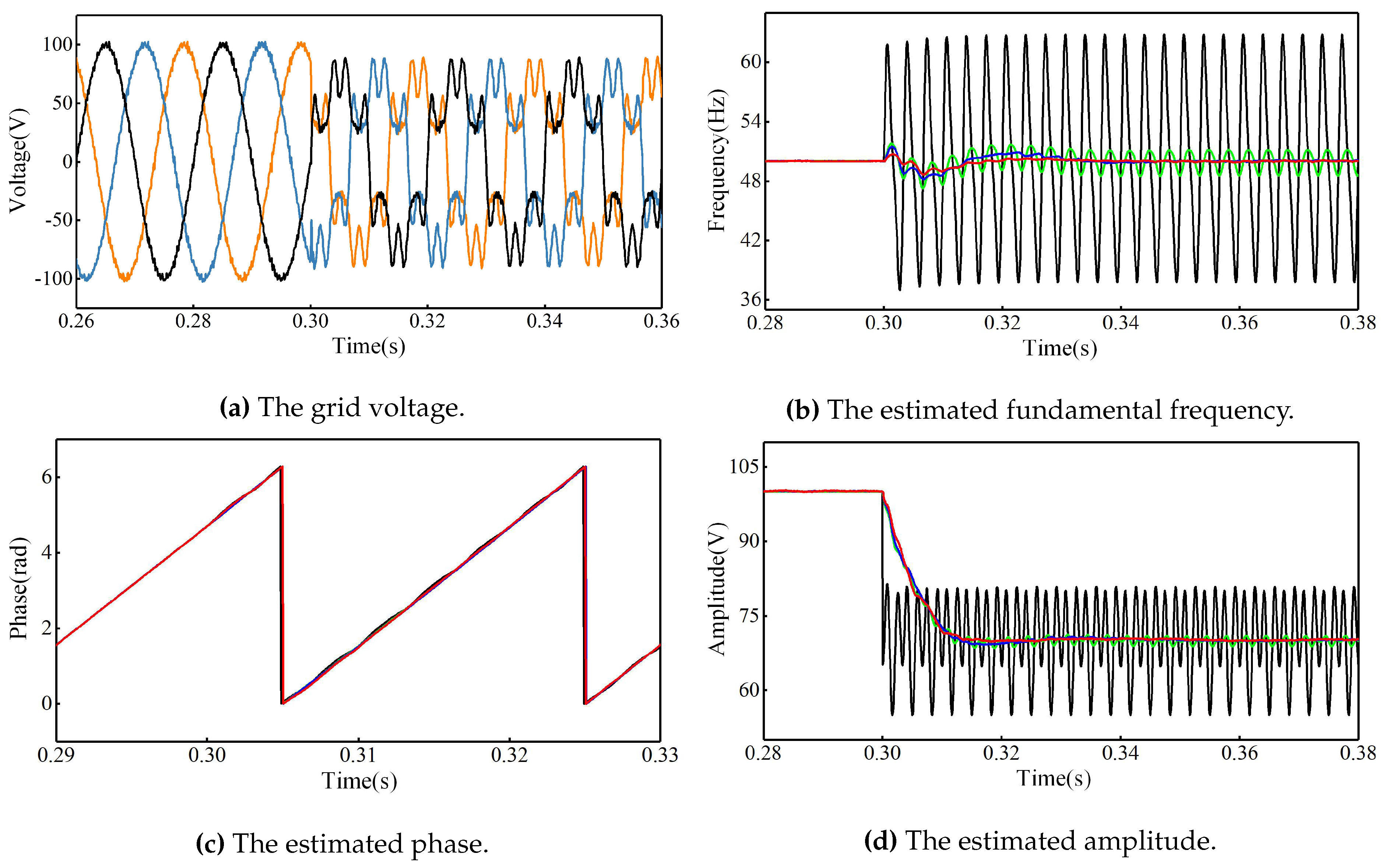
5.2.2. Performance Comparison between MDSOGI-IFLL and Other Synchronization Methods

In this part, experiments are carried out for performance comparison between MDSOGI-IFLL and other synchronization methods, including the SRF-PLL, the DDSRF-PLL [6], and the MCCF-PLL, synchronization technique proposed in [25] for three-phase grid-interfaced converters under unbalanced and distorted grid voltage. For the three PLLs, the parameters in the control loop, k p and k i , are set to 2 and 3, respectively. In addition, for the DDSRF-PLL, the cut-off frequency of the low-pass filter in the decoupling network is set to ω f = 222 rad/s. As for the MCCF-PLL, the cutoff frequency of ω c is the same as that in [25], with the value of 222 rad/s.

A. Unbalanced Voltage

In this test, the amplitude of the fundamental positive sequence is changed from 100 V to 70 V, and that of the fundamental negative sequence is increased to 30 V.
Figure 11 shows that the SRF-PLL is very sensitive to unbalance, and the estimated frequency has a ripple with the amplitude of 20 Hz in the steady state. All the others can precisely extract the phase and amplitude of the positive sequence with a settle time of 0.02 s. However, the frequency detection transient response of the MDSOGI-IFLL is superior to that of the DDSRF-PLL or the MCCF-PLL.

B. Distorted Voltage

The following test is carried out under the distorted grid voltage. At 0.3 s, the amplitude of the fundamental positive sequence is changed from 100 V (1 p.u.) to 70 V, and the fifth, seventh, and eleventh harmonic components are added on the grid voltage with the values of 0.15, 0.2, and 0.1 p.u., respectively.
From Figure 12, it can be seen that the performance of the SRF-PLL degrades further under the distorted voltage. In addition, the frequency estimated by DDSRF-PLL also has a larger ripple. Due to the use of the cross-feedback network, the MCCF-PLL and the MDSOGI-IFLL can still accurately extract the frequency and amplitude of the fundamental positive sequence.

C. Phase Jump

Figure 13 shows the experimental results when a 60 phase jump occurs at 0.3 s. It is obvious that each of three PLLs, i.e., the SRF-PLL, the DDSRF-PLL, and the MCCF-PLL, shows larger overshoot and longer settle time than MDSOGI-IFLL. As stated in [5], PLLs synchronize with the phase of the input signal, and hence, the accuracy and dynamical response of its estimation under transient conditions are highly influenced by phase angle jumps.

D. Brief Comparison

According to the experiments, Table 2 gives a brief comparison of the four synchronization methods to highlight their features.

6. Conclusions

To realize the fast and accurate acquisition of the information of the fundamental sequence under the unbalanced and distorted grid voltage, a synchronization method based on the MDSOGI-IFLL for the three-phase system is proposed in this paper. Through theoretical analysis, simulation, and experimental tests, several conclusions can be reached as follows:
  • According to the modeling analysis of the DSOGI-FLL, the drawback of the design method for the FLL unit proposed in [24] is pointed out. Based on the analysis, an improved design (referred as IFLL) that takes the fundamental negative sequence voltage into consideration in the design is proposed. The dynamic performance of the DSOGI-IFLL is independent of the variation of both the fundamental positive and the negative sequence voltage.
  • Under unbalanced grid voltage, the proposed MDSOGI-IFLL has a better transient performance than the MDSOGI-FLL in frequency detection when the grid frequency changes.
  • The MDSOGI-IFLL shows the outstanding performance of the estimation of the positive- and negative-sequence components even under the extremely unbalanced and distorted grid voltage. In addition, the MDSOGI-IFLL also could be used for selective harmonic compensation, islanding detection, and so on.

Author Contributions

Formal analysis, S.O.; Investigation, W.M. and W.X.; Methodology, W.M.; Project administration, S.O.; Software, W.M.; Writing—review & editing, W.M. and S.O.

Funding

This research was funded by the Natural Science Foundation of Guangdong Province (grant number 2016A030313476).

Conflicts of Interest

The authors declare no conflict of interest.

References

  1. Geng, H.; Xu, D.; Wu, B. A novel hardware-based all-digital phase-locked loop applied to grid-connected power converters. IEEE Trans. Ind. Electron. 2011, 58, 1737–1745. [Google Scholar] [CrossRef]
  2. Yada, H.K.; Murthy, M.S.R. Enhancement in Loop Filter of a Second Order Generalized Integrator-PLL by Using Proportional-Resonant Controller. J. Electr. Eng. 2016, 16, 18–23. [Google Scholar]
  3. Blaabjerg, F.; Teodorescu, R.; Liserre, M.; Timbus, A.V. Overview of control and grid synchronization for distributed power generation systems. IEEE Trans. Ind. Electron. 2006, 53, 1398–1409. [Google Scholar] [CrossRef]
  4. Kaura, V.; Blasko, V. Operation of a phase locked loop system under distorted utility conditions. IEEE Trans. Ind. Appl. 1997, 33, 58–63. [Google Scholar] [CrossRef]
  5. Chung, S.-K. A phase tracking system for three phase utility interface inverters. IEEE Trans. Power Electron. 2000, 15, 431–438. [Google Scholar] [CrossRef]
  6. Rodriguez, P.; Pou, J.; Bergas, J.; Candela, J.I.; Burgos, R.P.; Boroyevich, D. Decoupled double synchronous reference frame PLL for power converters control. IEEE Trans. Power Electron. 2007, 22, 584–592. [Google Scholar] [CrossRef]
  7. Ghartemani, M.K.; Khajehoddin, S.A.; Jain, P.K.; Bakhshai, A. Problems of startup and phase jumps in PLL systems. IEEE Trans. Power Electron. 2012, 27, 1830–1838. [Google Scholar] [CrossRef]
  8. Yuan, X.; Merk, W.; Stemmler, H.; Allmeling, J. Stationary-frame generalized integrators for current control of active power filters with zero steady state error for current harmonics of concern under unbalanced and distorted operation conditions. IEEE Trans. Ind. Appl. 2002, 38, 523–532. [Google Scholar] [CrossRef]
  9. Wei, M.; Chen, Z. A fast PLL method for power electronic systems connected to distorted grids. In Proceedings of the IECON 2007 33rd Annual Conference of the IEEE Industrial Electronics Society, Taipei, Taiwan, 5–8 November 2007; pp. 1702–1707. [Google Scholar]
  10. Arruda, L.N.; Silva, S.M.; Filho, B.J.C. PLL structures for utility connected systems. In Proceedings of the Conference Record of the 2001 IEEE Industry Applications Conference 36th IAS Annual Meeting (Cat. No.01CH37248), Chicago, IL, USA, 30 September–4 October 2001; Voulme 4, pp. 2655–2660. [Google Scholar]
  11. Yang, Y.; Frede, B. Synchronization in single-phase grid-connected photovoltaic systems under grid faults. In Proceedings of the 2012 3rd IEEE International Symposium on Power Electronics for Distributed Generation Systems (PEDG), Aalborg, Denmark, 25–28 June 2012; pp. 476–482. [Google Scholar]
  12. Yang, Y.; Hadjidemetriou, L.; Blaabjerg, F.; Kyriakides, E. Benchmarking of phase locked loop based synchronization techniques for grid connected inverter systems. In Proceedings of the 2015 9th International Conference on Power Electronics and ECCE Asia (ICPE-ECCE Asia), Seoul, Korea, 1–5 June 2015; pp. 2167–2174. [Google Scholar]
  13. Sohail, K.; Benoit, B.; Adolfo, A.; Wolfgang, G. On Small Signal Frequency Stability under Virtual Inertia and the Role of PLLs. Energies 2018, 11, 2372. [Google Scholar] [CrossRef]
  14. Rodriguez, P.; Luna, A.; Ciobotaru, M.; Teodorescu, R.; Blaabjerg, F. Advanced grid synchronization system for power converters under unbalanced and distorted operating conditions. In Proceedings of the IECON 2006 32nd Annual Conference on IEEE Industrial Electronics, Paris, France, 7–10 November 2006; pp. 5173–5178. [Google Scholar]
  15. Matas, J.; Miret, J.; de Vicuña, L.G.; Guzman, R. An adaptive prefiltering method to improve the speed/accuracy tradeoff of voltage sequence detection methods under adverse grid conditions. IEEE Trans. Ind. Electron. 2014, 61, 2139–2151. [Google Scholar] [CrossRef]
  16. Du, H.; Sun, Q.; Cheng, Q.; Ma, D.; Wang, X. An Adaptive Frequency Phase-Locked Loop Based on a Third Order Generalized Integrator. Energies 2019, 12, 309. [Google Scholar] [CrossRef]
  17. Rodriguez, P.; Luna, A.; Muñoz-Aguilar, R.S.; Etxeberria-Otadui, I.; Teodoresc, R. A stationary reference frame grid synchronization system for three-phase grid-connected power converters under adverse grid conditions. IEEE Trans. Power Electron. 2012, 27, 99–112. [Google Scholar] [CrossRef]
  18. Gonzalez-Espin, F.; Garcera, G.; Patrao, I.; Figueres, E. An adaptive control system for three-phase photovoltaic inverters working in a polluted and variable frequency electric grid. IEEE Trans. Power Electron. 2012, 27, 4248–4261. [Google Scholar] [CrossRef]
  19. Lee, K.; Lee, J.; Shin, D.; Yoo, D.; Kim, H. A novel grid synchronization PLL method based on adaptive low-pass notch filter for grid-connected PCS. IEEE Trans. Ind. Electron. 2014, 61, 292–301. [Google Scholar] [CrossRef]
  20. Zhang, B.; Zhou, K.; Wang, D. Multi-rate repetitive control for PWM DC/AC converters. IEEE Trans. Ind. Electron. 2014, 61, 2883–2890. [Google Scholar] [CrossRef]
  21. Han, Y.; Luo, M.; Zhao, X.; Guerrero, J.; Xu, L. Comparative performance evaluation of orthogonal-signal- generators based single-phase PLL algorithms—A survey. IEEE Trans. Power Electron. 2016, 31, 3932–3944. [Google Scholar] [CrossRef]
  22. Golestan, S.; Ramezani, M.; Guerrero, J.M.; Freijedo, F.D.; Monfared, M. Moving average filter based phase-locked loops: Performance analysis and design guidelines. IEEE Trans. Power Electron. 2014, 29, 2750–2763. [Google Scholar] [CrossRef]
  23. Hadjidemetriou, L.; Kyriakides, E.; Blaabjerg, F. A robust synchronization to enhance the power quality of renewable energy systems. IEEE Trans. Ind. Electron. 2015, 62, 4858–4868. [Google Scholar] [CrossRef]
  24. Rodriguez, P.; Luna, A.; Candela, I.; Mujal, R.; Teodorescu, R.; Blaabjerg, F. Multiresonant Frequency-Locked Loop for Grid Synchronization of Power Converters under Distorted Grid Conditions. IEEE Trans. Ind. Electron. 2011, 58, 127–138. [Google Scholar] [CrossRef]
  25. Guo, X.Q.; Wu, W.Y.; Chen, Z. Multiple-Complex Coefficient-Filter-Based Phase-Locked Loop and Synchronization Technique for Three-Phase Grid-Interfaced Converters in Distributed Utility Networks. IEEE Trans. Ind. Electron. 2011, 58, 1194–1204. [Google Scholar] [CrossRef]
  26. Riedle, B.D.; Kokotovic, P.V. Integral manifolds of slow adaptation. IEEE Trans. Autom. Control 1986, 31, 316–324. [Google Scholar] [CrossRef] [Green Version]
  27. Ciobotaru, M.; Teodorescu, R.; Blaabjerg, F. A new single phase PLL structure based on second order generalized integrator. In Proceedings of the 2006 37th IEEE Power Electronics Specialists Conference, Jeju, Korea, 18–22 June 2006; pp. 1–6. [Google Scholar]
Figure 1. Block diagram of the SOGI-FLL.
Energies 12 01023 g001
Figure 2. Block diagram of the DSOGI-FLL in [24].
Energies 12 01023 g002
Figure 3. The structure of the IFLL.
Energies 12 01023 g003
Figure 4. Simplified first-order linear frequency adaption system of the DSOGI-IFLL.
Energies 12 01023 g004
Figure 5. Structure of the MDSOGI-IFLL.
Energies 12 01023 g005
Figure 6. Bode diagram of the MDSOGI-IFLL.
Energies 12 01023 g006
Figure 7. The grid voltage considered in the simulation.
Energies 12 01023 g007
Figure 8. Estimated frequency.
Energies 12 01023 g008
Figure 9. Simulation results. (a) Harmonics estimated by MDSOGI-FLL. (b) The estimated error in phase A of each harmonic component (for example, the estimated error in phase A of 5th harmonic is obtained by subtracting the estimated value with reference). (c) Harmonics estimated by MDSOGI-IFLL.
Energies 12 01023 g009
Figure 10. Waveforms of the grid voltage and frequency estimated by the MDSOGI-FLL (green line) and the MDSOGI-IFLL (red line).
Energies 12 01023 g010
Figure 11. Waveforms of the grid voltage and estimated parameters by SRF-PLL (black line), DDSRF-PLL (green line), MCCF-PLL (blue line) and MDSOGI-IFLL (red line).
Energies 12 01023 g011
Figure 12. Waveforms of the grid voltage and estimated parameters by SRF-PLL (black line), DDSRF-PLL (green line), MCCF-PLL (blue line) and MDSOGI-IFLL (red line).
Energies 12 01023 g012
Figure 13. Waveforms of the grid voltage and estimated parameters by SRF-PLL (black line), DDSRF-PLL (green line), MCCF-PLL (blue line) and MDSOGI-IFLL (red line).
Energies 12 01023 g013
Table 1. Parameters of the grid voltage during the fault.
Voltage ComponentValue [p.u.]
Case 1Case 2Case 3
Fundamental positive sequence0.60.60.6
Fundamental negative sequence0.20.40.6
5th harmonic0.20.20.2
7th harmonic0.150.150.15
11th harmonic0.10.10.1
Table 2. Brief comparison of the four synchronization methods.
Pros and ConsAdvantagesDisadvantages
Synchronization Methods
SRF-PLLThe structure of SRF-PLL is simple. It is easy to design and it can effectively detect the amplitude, phase, and frequency of the grid voltage with perfect steady-state and dynamic response under the idea grid voltage.It is sensitive to unbalance and harmonics.
DDSRF-PLLIt can accurately extract the positive and negative sequence components of the voltage with good dynamic performance and good frequency adaptability even when the grid voltage is unbalanced.Its ability to attenuate low-order harmonics is insufficient. In addition, its transient response is highly influenced by the phase-angle jumps of the input signal.
MCCF-PLLThe structure of MCCF is flexible. Through the cross-feedback network, it can accurately detect the information of grid voltage in the steady state even under the unbalanced and distorted grid voltage.To obtain good performance under the distorted grid voltage, its structure will be more complex, thereby, requiring more DSP resource compared to SRF-PLL or DDSRF-PLL. Since its frequency-adaptive depends on the cascaded PLL, its transient response is highly influenced by the phase-angle jumps of the input signal.
MDSOGI-IFLLIt shows perfect performance under the unbalanced and distorted grid voltage. Due to the FLL, the performance of frequency detection is the best. Hence, it is relatively insensitive to phase jump.With the number of the DSOGI used in the cross-feedback network increasing, it requires more DSP resource compared to SRF-PLL or DDSRF-PLL.

