Mixed Convection and Entropy Generation of an Ag-Water Nanofluid in an Inclined L-Shaped Channel


1
Department of Engineering, Mahdishahr Branch, Islamic Azad University, Mahdishahr 75915-35618, Iran
2
Mechanical Engineering Department, College of Engineering, University of Basrah, Basrah 61004, Iraq
3
Mechanical Engineering Department, Prince Mohammad Bin Fahd University, Al-Khobar 31952, Saudi Arabia
4
Prince Sultan Endowment for Energy and Environment, Prince Mohammad Bin Fahd University, Al-Khobar 31952, Saudi Arabia
5
Department of Mathematics, Babeş-Bolyai University, 400084 Cluj-Napoca, Romania
*
Author to whom correspondence should be addressed.
Energies 2019, 12(6), 1150; https://0-doi-org.brum.beds.ac.uk/10.3390/en12061150
Submission received: 17 February 2019
/
Revised: 11 March 2019
/
Accepted: 19 March 2019
/
Published: 25 March 2019
(This article belongs to the Special Issue Heat Transfer Enhancement)
Abstract
:This paper investigates the mixed convection and entropy generation of an Ag-water nanofluid in an L-shaped channel fixed at an inclination angle of 30° to the horizontal axis. An isothermal heat source was positioned in the middle of the right inclined wall of the channel while the other walls were kept adiabatic. The finite volume method was used for solving the problem’s governing equations. The numerical results were obtained for a range of pertinent parameters: Reynolds number, Richardson number, aspect ratio, and the nanoparticles volume fraction. These results were Re = 50–200; Ri = 0.1, 1, 10; AR = 0.5–0.8; and φ = 0.0–0.06, respectively. The results showed that both the Reynolds and the Richardson numbers enhanced the mean Nusselt number and minimized the rate of entropy generation. It was also found that when AR. increased, the mean Nusselt number was enhanced, and the rate of entropy generation decreased. The nanoparticles volume fraction was predicted to contribute to increasing both the mean Nusselt number and the rate of entropy generation.
1. Introduction
Despite its active classification, mixed convection flow is still a useful tool of heat transfer augmentation. It provides efficient cooling (or heating) for many engineering applications, such as for building ventilation, cooling gas turbine blades, cooling electronic devices, cooling chemical reactors, emergency cooling systems of nuclear reactors, etc. Many studies have revealed that the mixed convection flow have different issues based on the geometry of the channel or the duct. However, most researchers compromise between the heat transfer enhancement and the associated pressure losses. Shah and London [1] have given an early and very good review of forced convection using regular duct geometry. In the early designs of a corrugated channel, the pressure drop reaches up to six times that of a smooth channel, while the heat transfer augmentation was aut 3.5 times [2]. Separation and reattachment of the flow in backward- and forward-facing steps were proven to give an improvement to efficient heat transfer [3]. Finned or ribbed wall surfaces are also implemented as a passive strategy to improve the mixing of flow and increase the area of heat transfer [4,5,6].
For the ventilation requirements to obtain optimal performance and space limitation, the flow in a channel can be designed into different shapes. Mezrhab et al. [7] considered the surface radiation together with natural convection in a vented T-shaped cavity. They observed that the convective heat transfer increased with cavity height. Kasaeipoor et al. [8] investigated the mixed convection of a nanofluid in a vented T-shaped cavity in the presence of a uniform magnetic field. It was assumed that the flow entered from the bottom (i.e., the vertical leg) and exited from the horizontal leg. They reported that for the dominant forced convection, the maximum heat transfer occurred when the vertical leg was very thin in comparison to the horizontal leg. However, for the dominant natural convection, the maximum heat transfer occurred when the cavity shape was mostly square. Biserni et al. [9] optimized the geometry of an H-shaped cavity intrusion into a two-dimensional conducting body with uniform heat generation using Bejan’s constructal theory [10]. They demonstrated that it was necessary to evolve a complex geometry in order to improve heat transfer performance. Marcondes and Maliska [11] addressed a numerical method for handling the inlet velocity profile for open-ended channels. Their calculations were conducted for an L-shaped channel. An L-shaped duct plays a vital role in cooling the trailing blade of a gas turbine. Shih et al. [12] discussed an L-shaped duct with the presence of pin fins in sand particles for rotating and non-rotating conditions. Pardeshi [13] investigated the L-shaped cooling passage for the trailing edge of a gas turbine blade with a combination of ribs and pin fins under rotating and non-rotating conditions. Although the L-shaped geometry has been widely investigated, the investigations are limited to closed enclosure [14,15,16].
When the heat transfer augmentation is a challenging issue, improving the properties of the working fluid can reinforce the mixed convection. Over the past two decades, nanofluids have been demonstrated as a powerful and interesting field in heat transfer enhancement. A nanofluid is the dispersal of solid nanoparticles with superior thermal conductivity into the working base fluid [17]. A nanofluid is a familiar strategy in enclosures [18], nevertheless, they are used in vented cavities [8,19,20,21,22] and channels [23,24,25]. In practice, these vented cavities and channels are parts of an enclosed loop system because the nanofluid is toxic and expensive. Therefore, it is impractical to discharge a nanofluid into the environment. The common feature among these studies (except in some situations) was that the mixed heat transfer augments with increasing volume fraction of nanoparticles. Nanofluids serve in lowering the separation and in turn minimize the secondary flow, which benefits heat transfer enhancement.
A growing interest in improving the thermodynamic performance of thermal systems has led to extensive studies of exergy utilization and entropy generation. Fluid friction and irreversible heat transfer are the main reasons causing entropy generation and hence, attenuate the available work of the system. Bejan [26,27,28] published essential studies discovering the reasons that cause the generation of entropy in applied thermal engineering using the second law of thermodynamics. Following Bejan’s conclusions from these books, several studies have been published in this topic under different engineering circumstances. An analysis of entropy generation in enclosures with and without a nanofluid can be found in several past studies [29,30,31,32,33,34,35,36,37]. These studies recorded an increase in entropy generation with an increasing ratio of inertial to viscous forces, while there was conflict between heat transfer irreversibility and the volume fraction of nanoparticles. In addition, the inclination of enclosures was found to have a notable effect on entropy generation. In some of these studies, it was found that the magnetic field could reduce entropy generation. Regarding the regular channel [38,39,40,41,42,43,44] and step channel [45,46], it was found that the Reynolds number increases the rate of the generation of entropy.
During a continuous literature survey, we did not find a study that concentrated on entropy generation in a wide variety of irregular ducts. Thus, in this paper, we present an analysis of entropy generation in a nanofluid in an L-shaped duct with a mixed convective flow. We used this geometry because it is very important and useful in cooling systems of nuclear and chemical reactors, electronic components, etc.
2. Mathematical Modelling
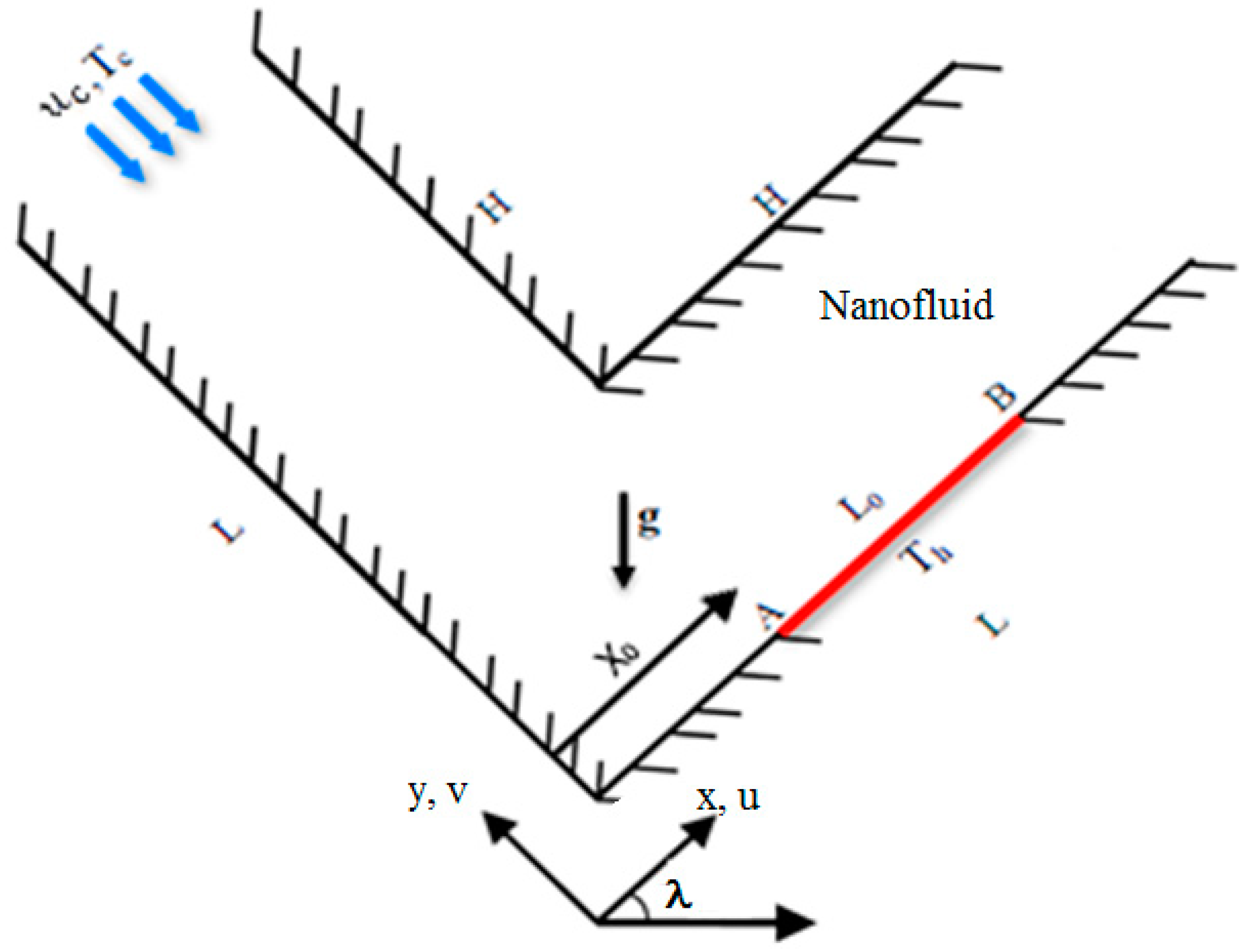
As shown in Figure 1, our problem was a two-dimensional L-shaped duct, where the x-axis was measured along the bottom (i.e., the horizontal leg) of the channel, while the y-axis was measured along the vertical leg of the channel. The aspect ratio of the inner side H to the outer side L is AR. The flow enters in the negative y-direction, turns in 90°, and exits from the horizontal leg. A heat source of length L0 was fixed at the bottom of the horizontal channel at a distance X0 from the origin. The channel was tilted with an angle of λ = 30° to the horizontal axis. Two approaches exist for modeling nanofluid heat transfer: single-phase and two-phase. In the single-phase model, a uniform volume fraction distribution is assumed for nanofluids. In other words, the viscosity and thermal conductivity of nanofluids are formulated by a volume fraction and nanoparticle size, then continuity, momentum, and energy equations are solved for nanofluids. In the two-phase model, the volume fraction distribution equation is added to other conservation equations [47,48,49,50,51,52,53]. However, most comparative studies have concluded that the two-phase models predict almost identical hydrodynamic fields to the single-phase ones, but this is not the case for thermal fields. Haghshenas Fard et al. [54] showed that the average relative error between experimental data and the numerical results based on single- and two-phase models were 16% and 8%, respectively. The discrepancy between the two models, about 8%, arose for Reynolds number ranges between 700 and 2050.
This study was carried out for a steady-state case and the flow was assumed laminar, incompressible, and Newtonian. The buoyancy force is considered based on the Boussinesq’s approximation. Nanoparticles with a volume fraction φ were uniformly dispersed within the base fluid, where they were in thermodynamic equilibrium. The dimensionless form of the mass, momentum, and energy equations are as follows:
with the following boundary conditions:
- At solid walls: U = V = 0;
- Inlet port: U = 0, V = 1, and ;
- Outlet port: V = 0, , ;
- At heat source: ;
- At the others solid walls: , where n is a normal vector.
The local Nusselt number can be written as:
The mean Nusselt number can be expressed as:
The dimensional relation of entropy generation is given by:
and the non-dimensional form of the above equation is:
where
The total entropy generation throughout the whole domain can be defined as:
The criterion of thermal performance against the generation of entropy that was proposed in past papers [36,37] is defined here in an inverse form as:
In this form, we get a better display to this criterion, where its maximum values correspond to the best thermal performance.
Nanofluid Relations
Table 1 presents the individual thermo-physical properties of Ag-nanoparticles and water. In this study, we considered the Ag-water nanofluid with the following thermo-physical properties.
3. Numerical Solutions
3.1. Methodology
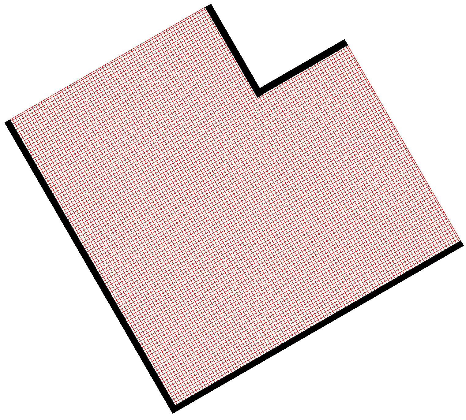
We used the collected grid finite volume method for the numerical solution of the governing Equations (1)–(4). The computational domain was uniformly discretized (Figure 2) using a displaced network method with the central difference scheme to discretize diffusive terms and the up-wind scheme for convective terms. The SIMPLE algorithm [57] was used for pressure–velocity linkage. The numerical efforts were achieved by an in-house-built FORTRAN computer code (FORTRAN 90). An iterative procedure was invoked with the following convergence criterion:
where is U, V or θ. Once the variables U, V, and θ were computed, the Nusselt number, entropy generation, and the performance criterion were calculated.
3.2. Validations
To test grid independency, we calculated the mean Nusselt number for a wide variety of grid sizes for a Richardson number Ri = 1, AR = 0.5, nanoparticles volume fraction φ = 0.04, and λ = 30° for two different Reynolds numbers (Re = 50 and 200). As presented in Table 2, the grid size of 120 × 120 was found to be the most suitable from the accuracy and time-consumption points oview, and thus we used it in this study.
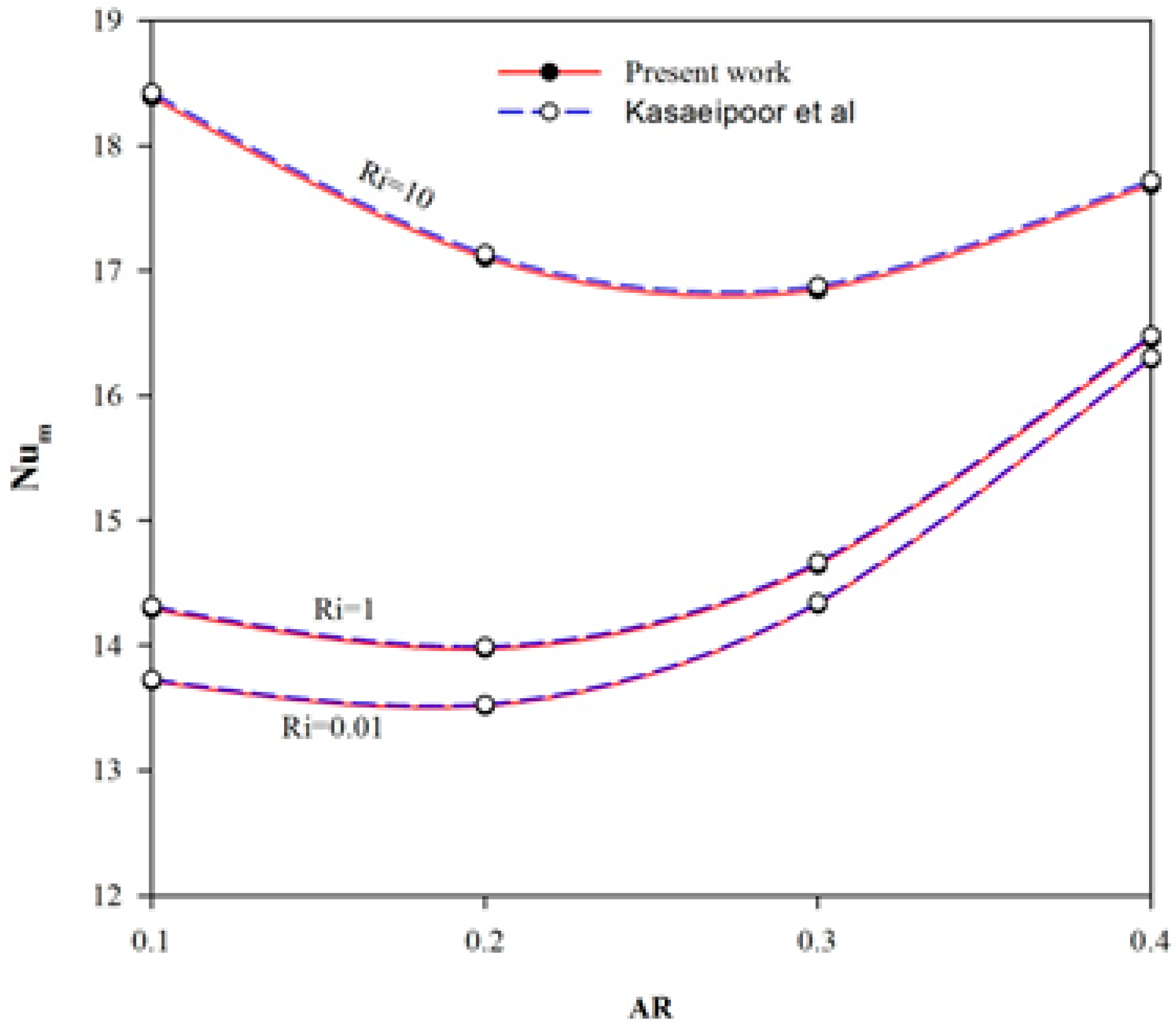
This validation was further supported by making a comparison with a vented T-shaped cavity addressed by Kasaieepoor et al. [8] for a T-shaped enclosure at Re = 100 for various Ri and AR values. The results of the comparison are presented in Figure 3, which implied a very strong agreement. This improved the confidence in our built-in code.
4. Results and Discussion
The current study was achieved by varying four pertinent parameters. These were the Reynolds number Re, Richardson number Ri, aspect ratio AR, and the nanoparticles volume fraction φ. Pure water (Pr = 6.26) was considered as the base fluid and the inclination of the channel was λ = 30°, where these two values were fixed throughout the current study. The effects of the first three pertinent parameters were categorized into three subsections, while the effect of the nanoparticles volume fraction was examined inclusively within these three subsections.
4.1. Effect of the Reynolds Number
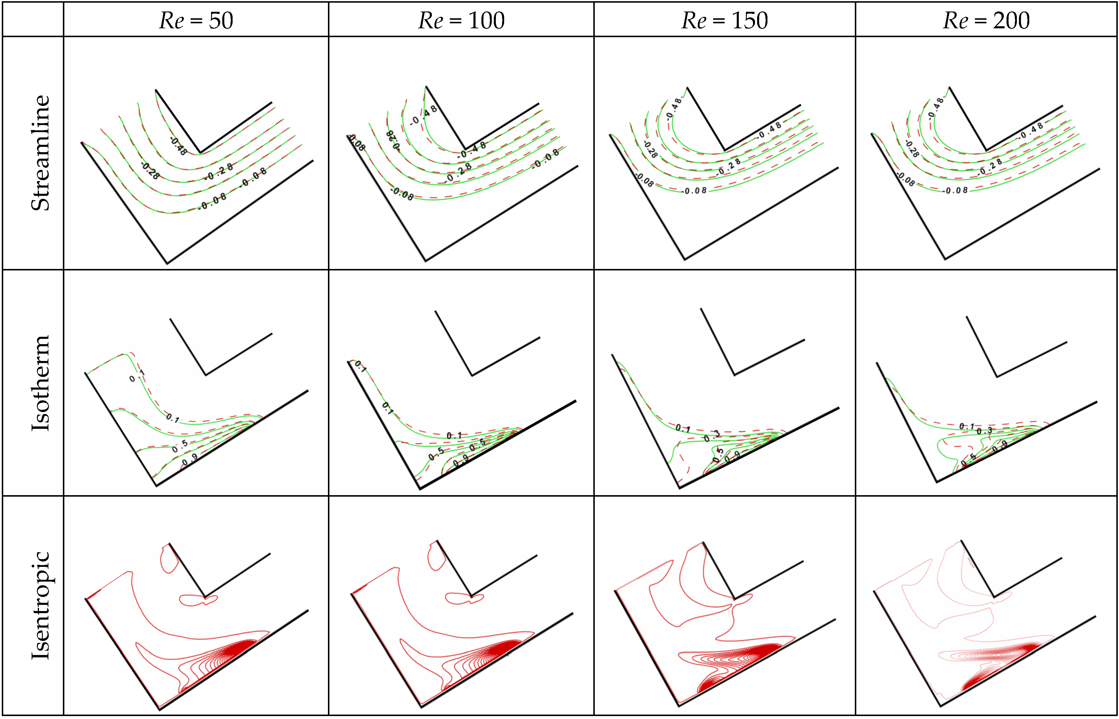
To study the effect of the Reynolds number, we fixed the Richardson number value at Ri = 1 and the aspect ratio AR at 0.5. Figure 4 presents the contours of streamlines, isotherms, and isentropic lines for different values of the Reynolds number Re = 50–200 with an interval of 50. The streamlines tended to be narrower with increasing values of Re and turned violently through the horizontal leg of the channel. The effect of the nanoparticles on the streamlines (dashed lines) became prominent at higher values of the Reynolds number, where the density of the nanofluid, which governs the inertial force, already increased with the addition of nanoparticles. Increasing the Reynolds number led to increasing the mass flow rate, hence increasing heat transfer. As such, the thermal boundary layer close to the heat source looked thinner with increasing Re and resulted in an isothermal region away from the lower inner corner. This was an indication of a larger heat transfer. Again, the isotherms of the nanofluid were noticeably distinguished with high Re values. In accordance to the isentropic lines, the source of the entropy generation was mainly due to the heat transfer irreversibility that was close to the heat source, even with higher Re values where the friction of the fluid contributed to generating entropy as shown with Re = 150 and 200.
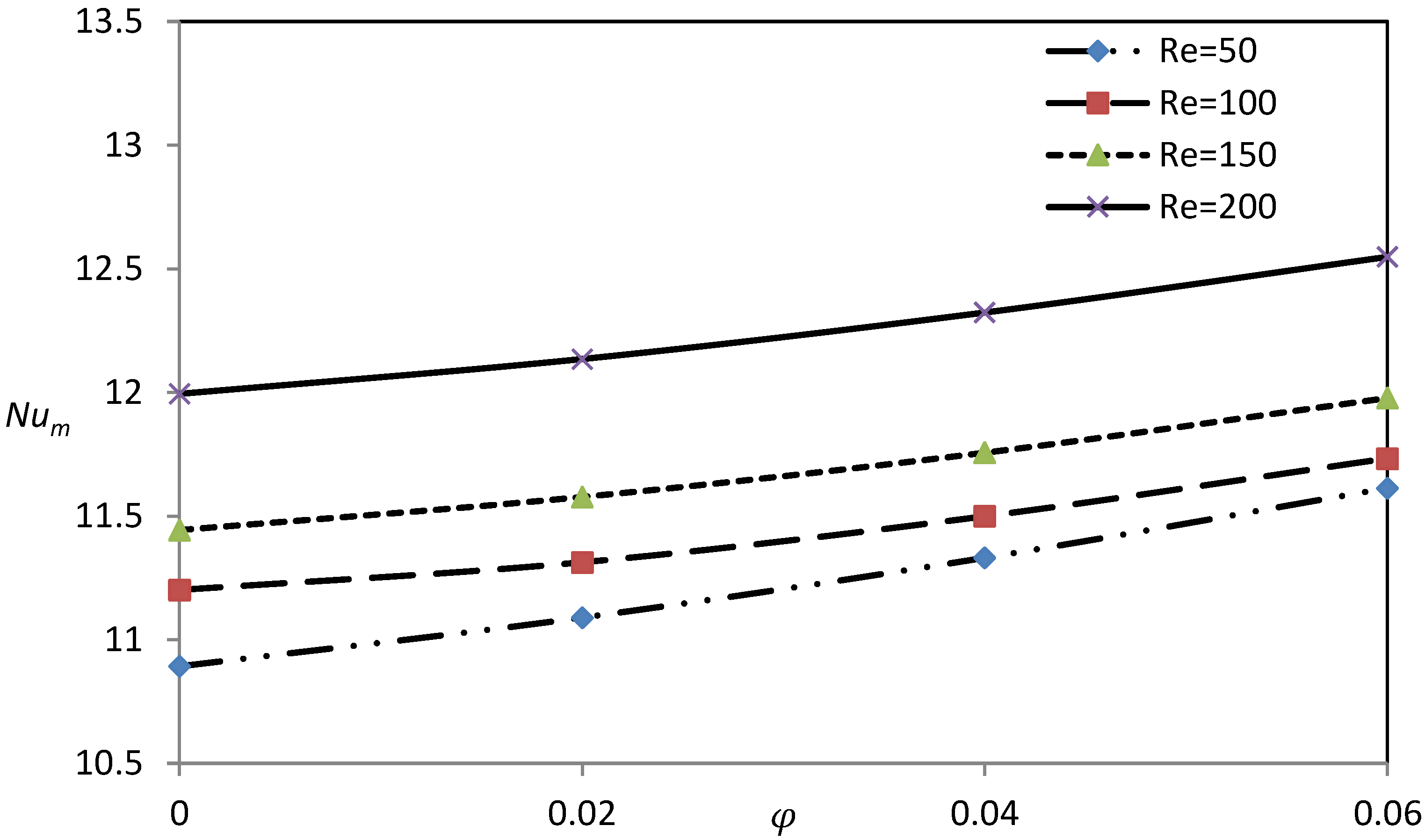
Figure 5 presents variations of the mean Nusselt number with the nanofluid volume fraction φ for Re = 50–200. The convective heat transfer increased with the Reynolds number and this was due to increasing the mass flow rate of the fluid/nanofluid, which augmented the overall heat transfer. Increasing the value of φ enhanced the thermal conductivity and the heat capacity of the nanofluid. Thus, we observed that the mean Nusselt number Num increased gradually with φ. However, the increment of Num with φ at Re = 50 was faster than the other higher Re values. This refers to the relatively low effect of the inertial force against the enhancement raised by the thermal conductivity and heat capacity.
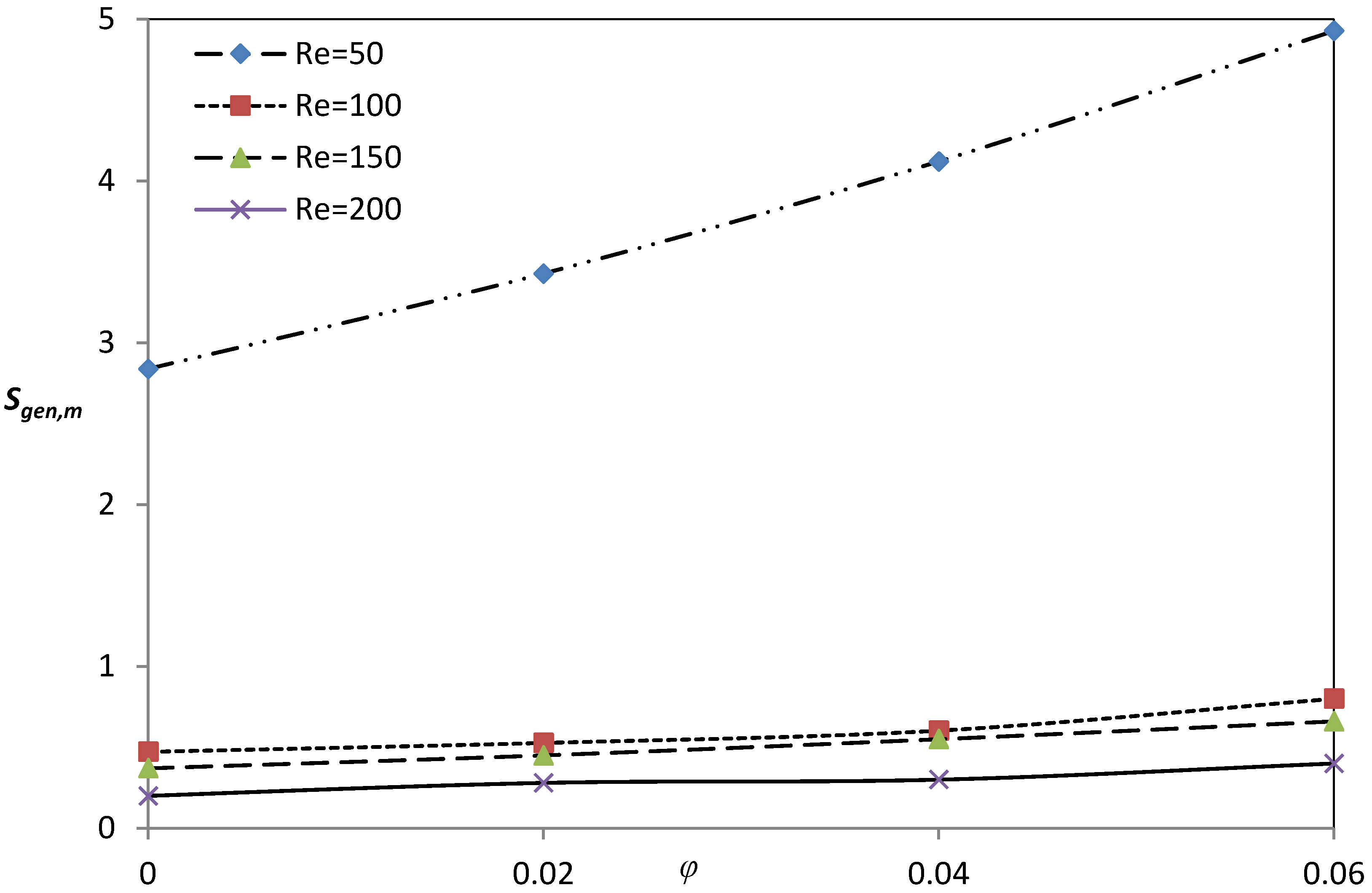
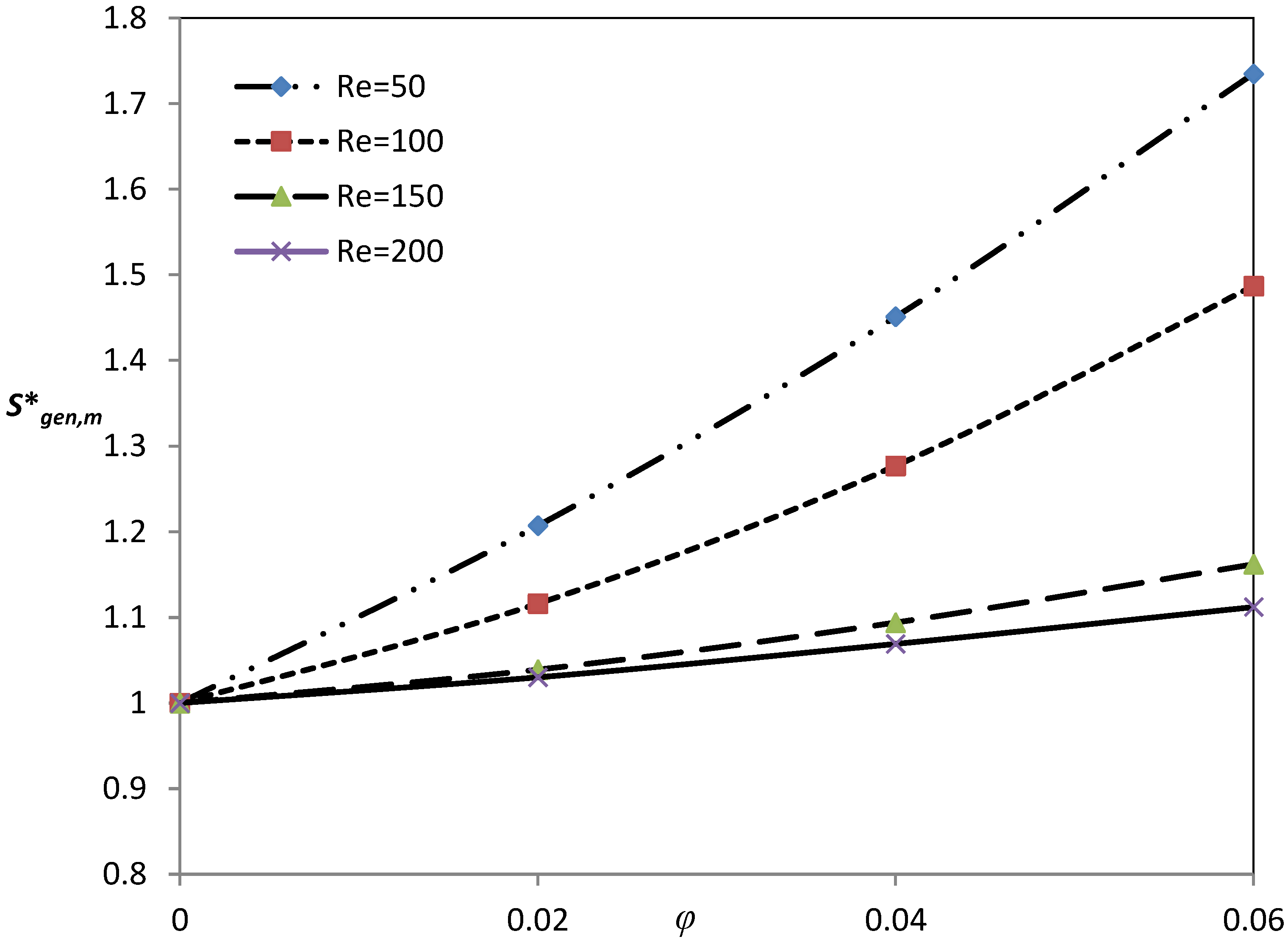
Figure 6 shows a drastic reduction of entropy generation when the Reynolds number increased from 50 to 100. By increasing Re greater than 100, the decrease of the entropy generation became slight. This reduction of entropy generation can be attributed to the decrease of the fluid friction irreversibility because of the inverse proportionality between the nanofluid friction factor and the Reynolds number. Increasing the volume fraction of nanoparticles caused an increase in entropy generation, particularly at low Re values as shown in Figure 6. We attributed this increase to the increase in the exchange of energy and to viscous forces, as a result of the irreversibility of the heat transfer and fluid friction augment.
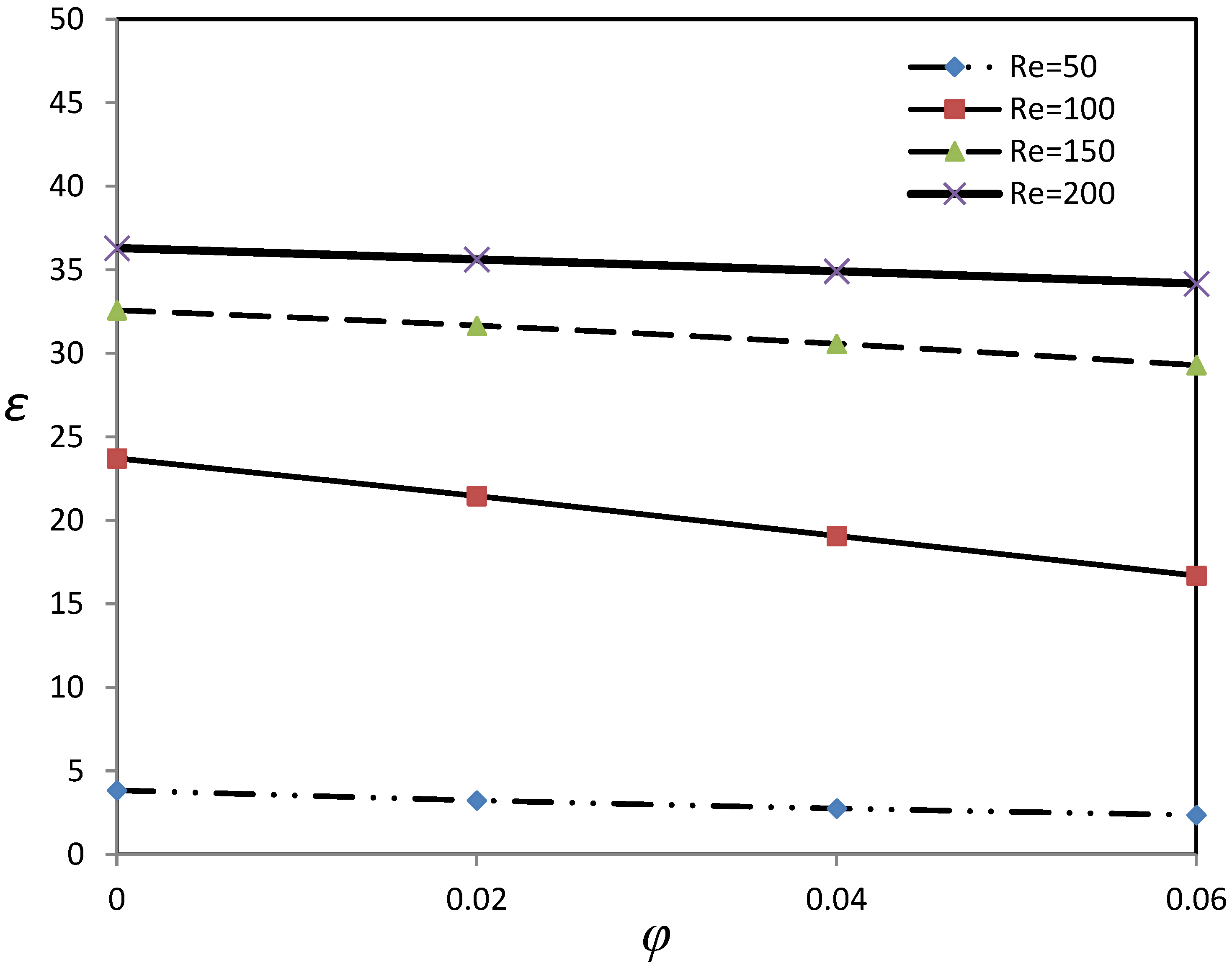
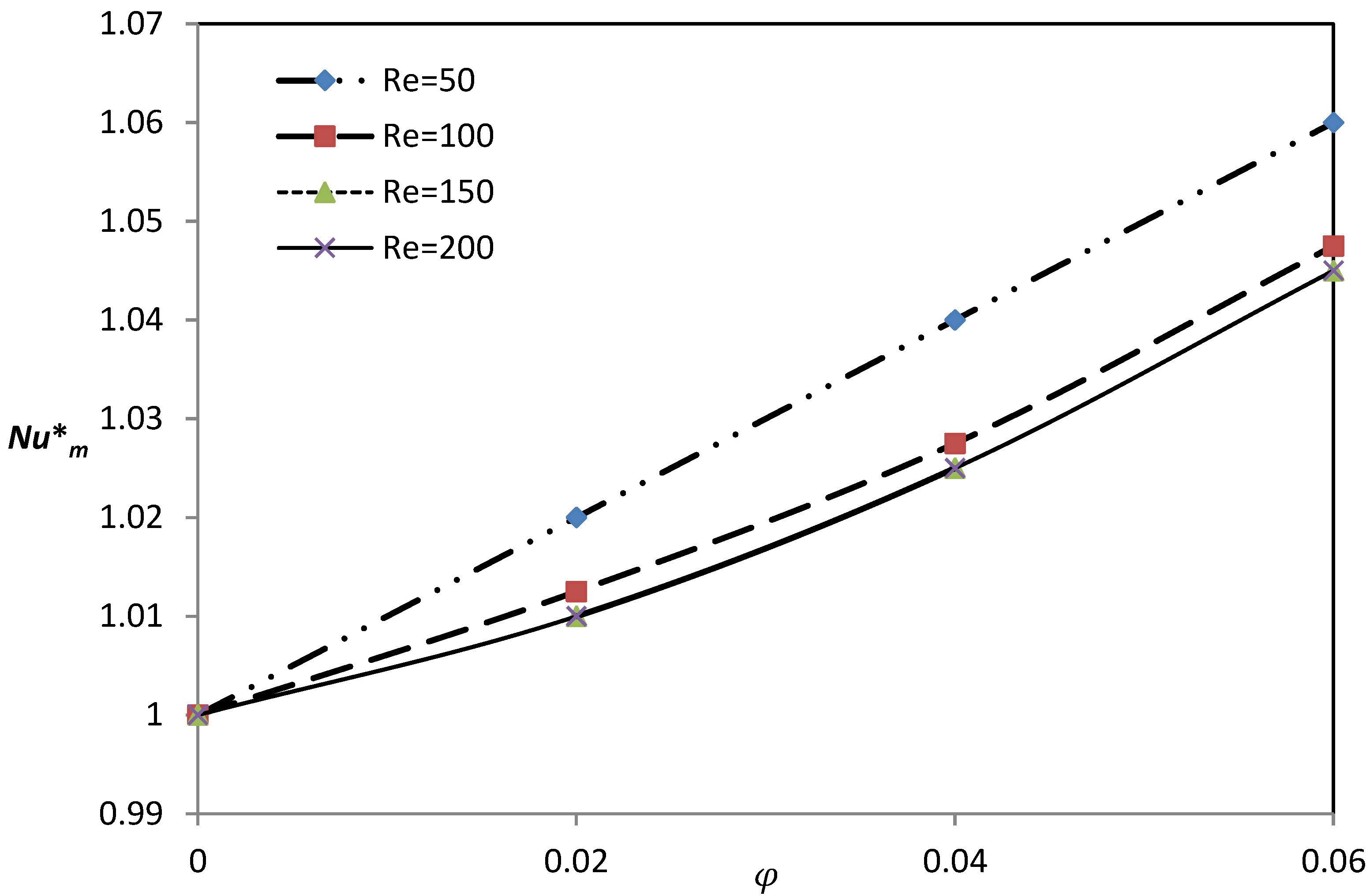
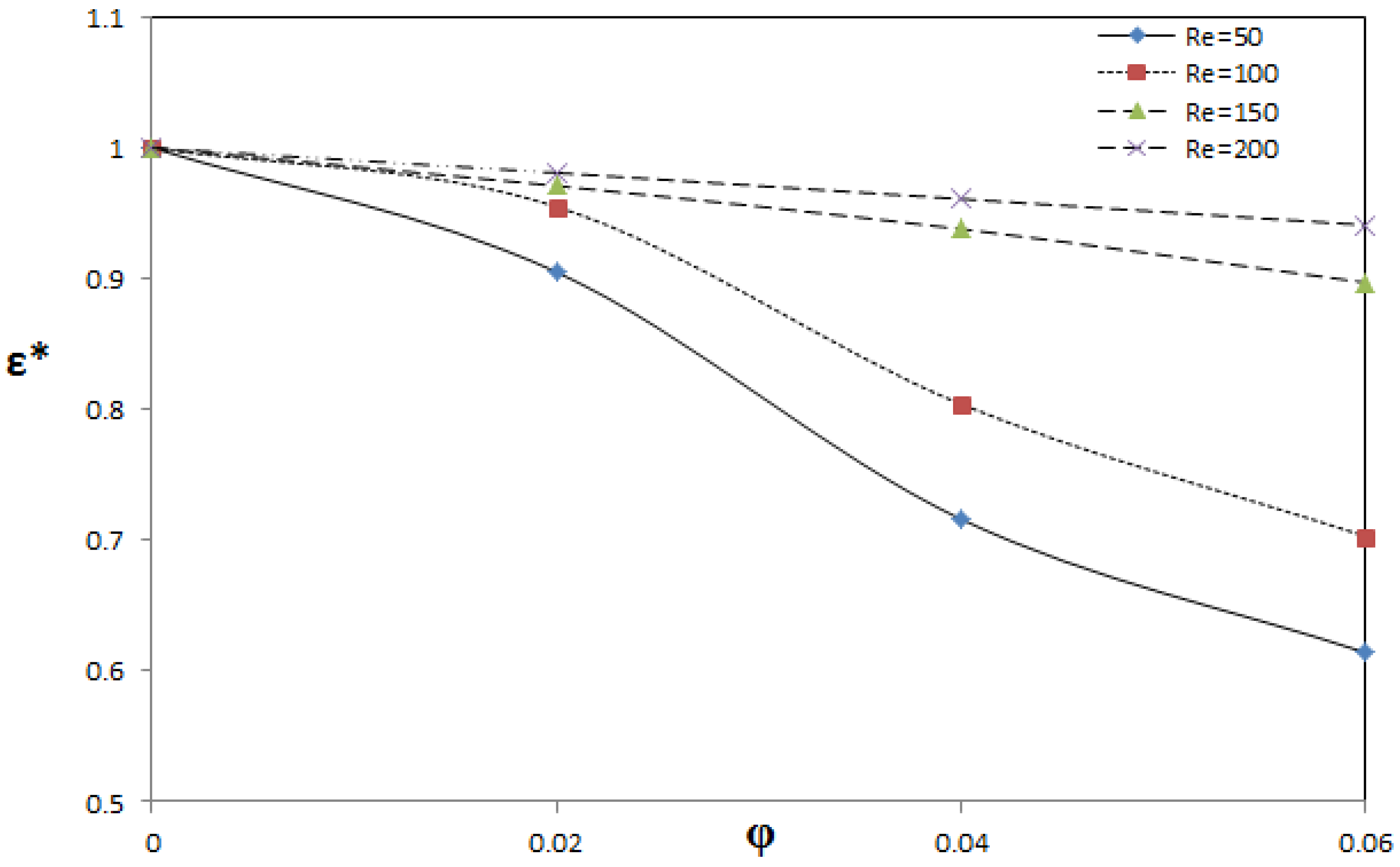
The criterion that quantifies convective heat transfer to generated entropy (ε), which was discussed well in Ismael et al. and Chamkha et al. [36,37], is shown in Figure 7. Referring to the variations of Num and Sgen,m with Re and φ, one can understand the behavior of the ε criterion which is portrayed in Figure 7, where this figure shows the improvement of the utilized thermal energy with an increasing Reynolds number where the minimum irreversibility losses could be obtained with Re = 200. The volume fraction of the nanoparticles could slightly reduce this criterion. To gain a closer view into the effect of the nanofluid, we normalized the mean Nusselt number Num, the total entropy generation Sgen,m, and the ε by the their corresponding values for a pure base fluid (φ = 0). The results are gathered in Figure 8, Figure 9 and Figure 10. These figures demonstrate the reduction of the ε criterion with the nanoparticles volume fraction in low Reynolds numbers.
4.2. Effect of the Richardson Number
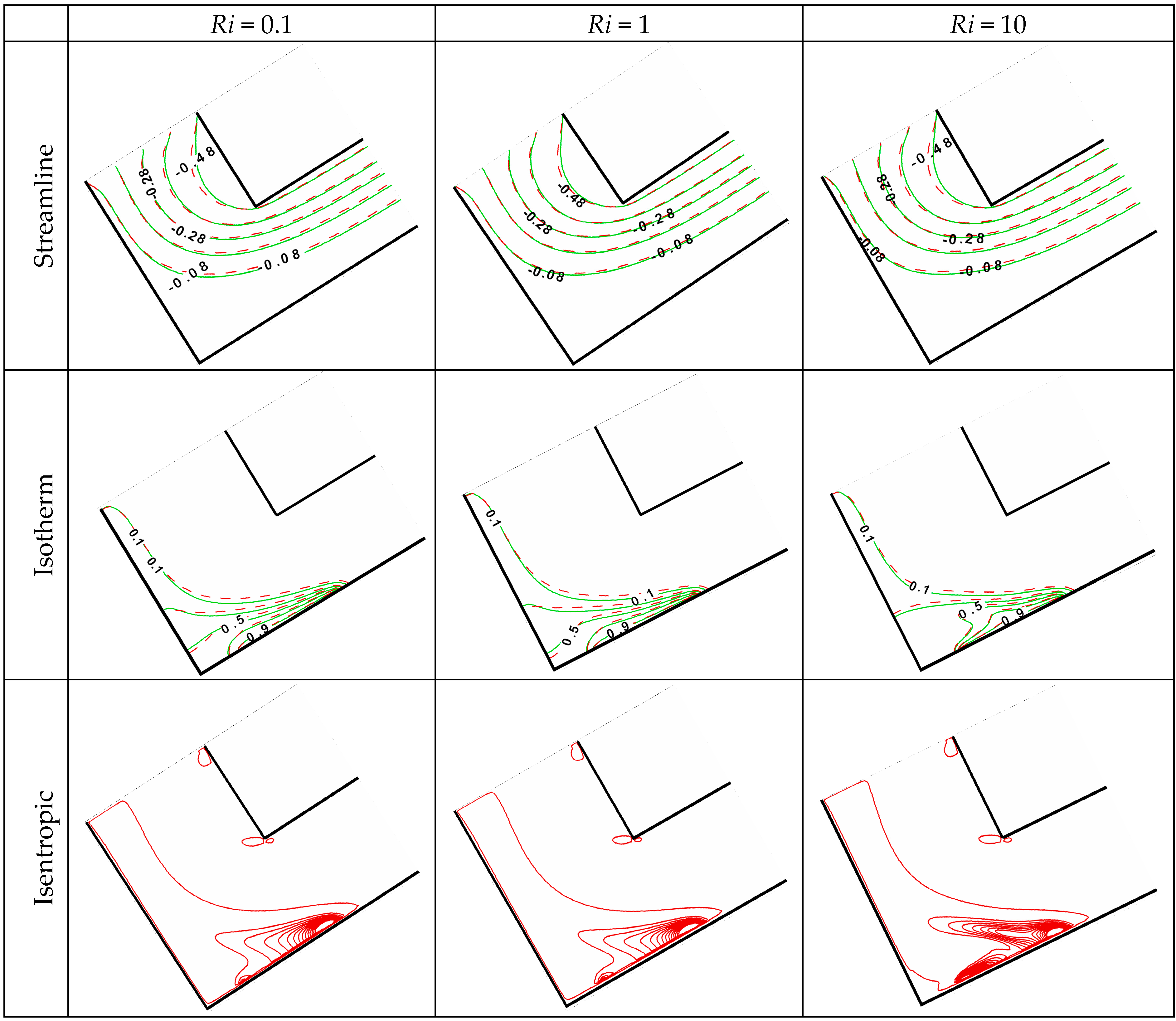
To investigate the effect of the Richardson number Ri, we fixed Re at 100 and AR at 0.5. Figure 11 depicts inconsiderable variations in the streamline and isotherm maps when the convection mode changed from forced (Ri = 0.1) to natural (Ri = 10), except for the isentropic lines, where a high concentration of isentropic lines was predicted close to the heat source at Ri = 10. The nanofluid (dashed) lines also demonstrated inconsiderable variations with Ri.
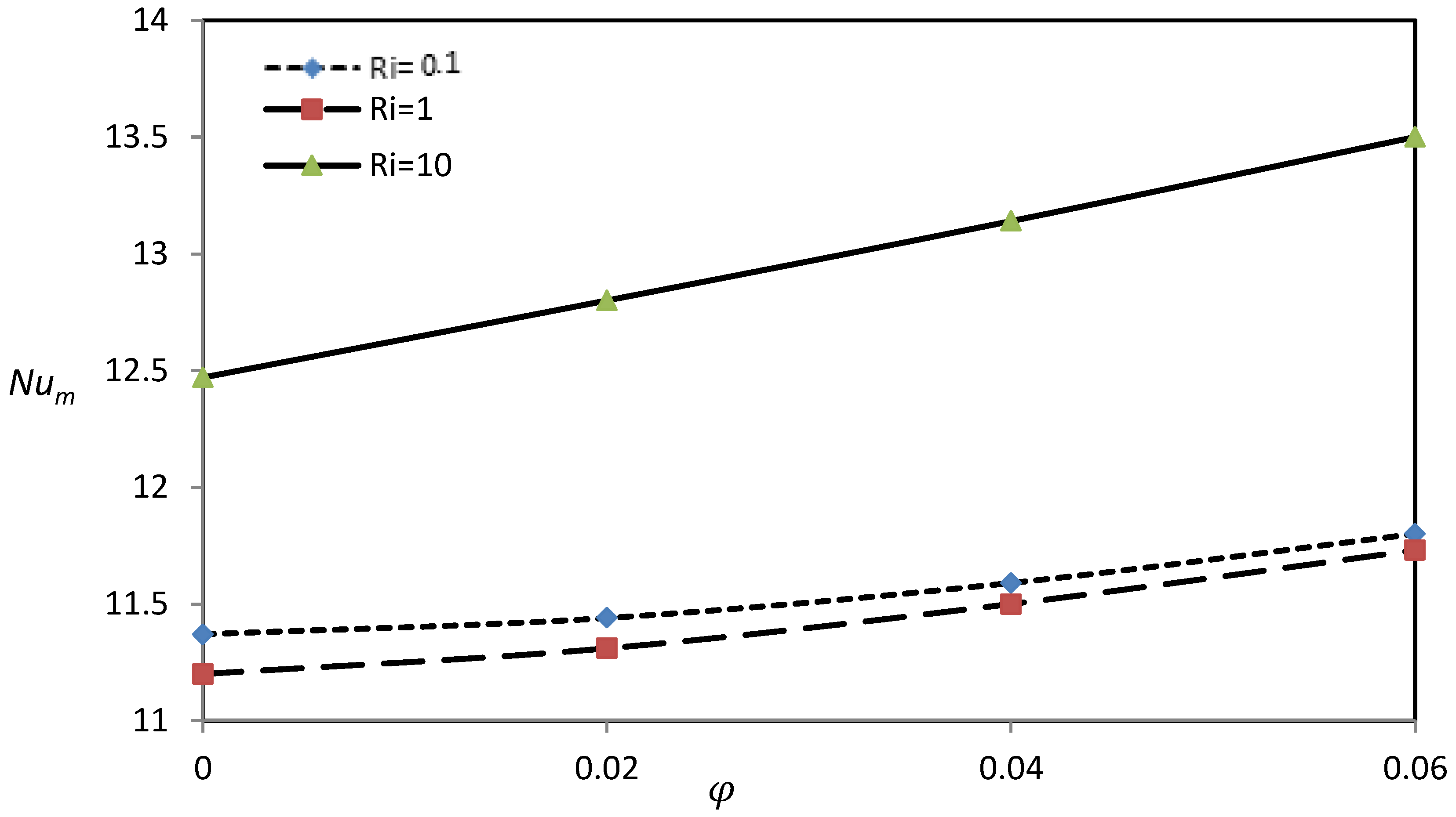
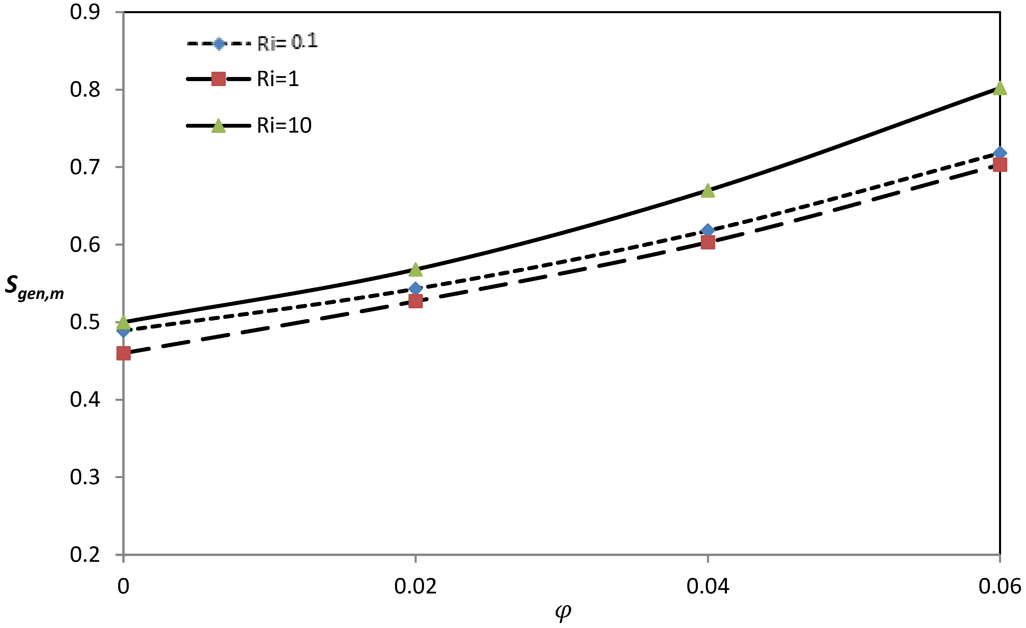
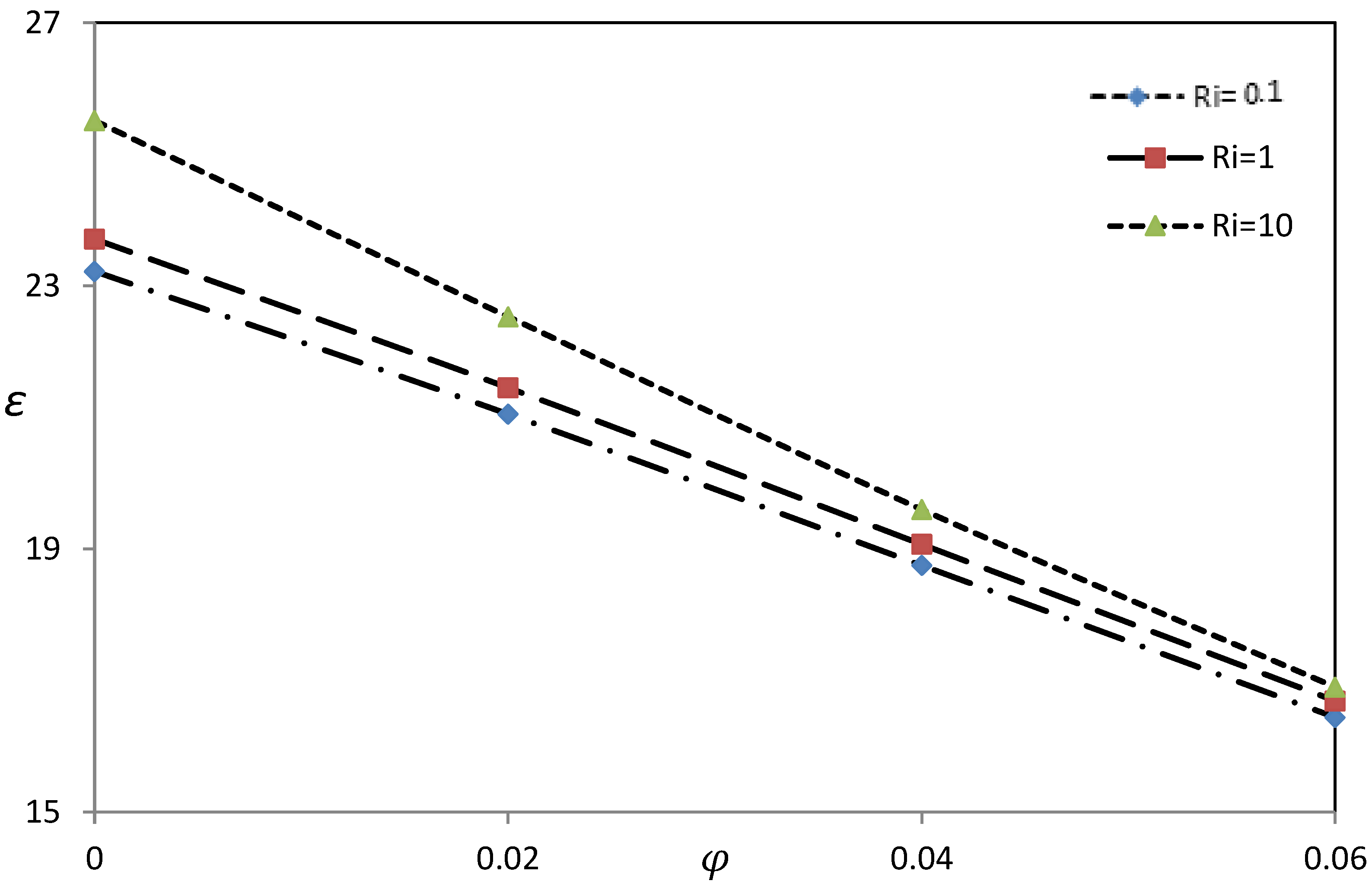
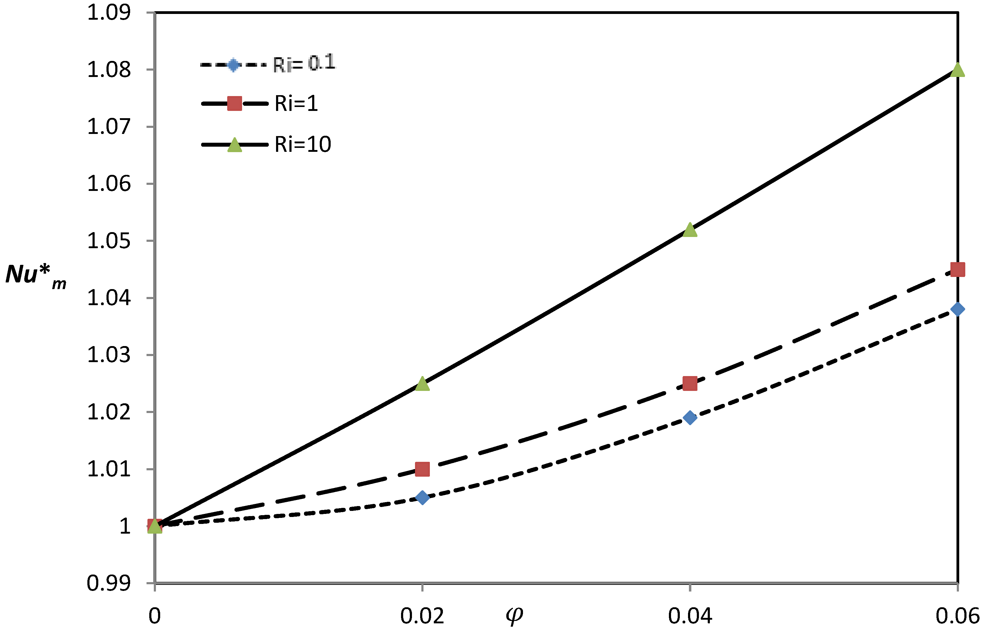
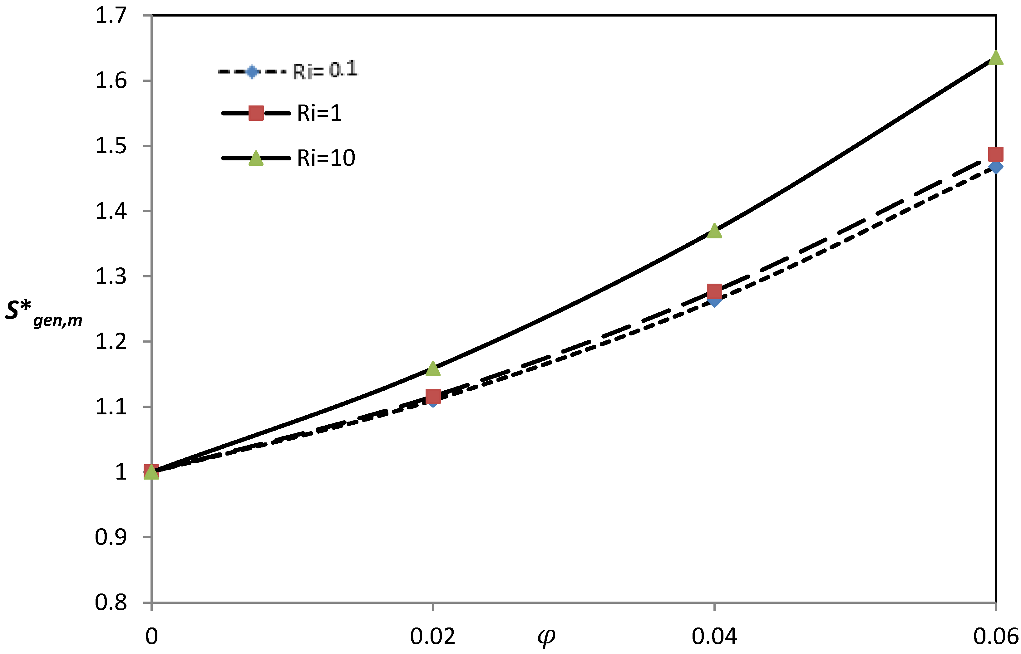
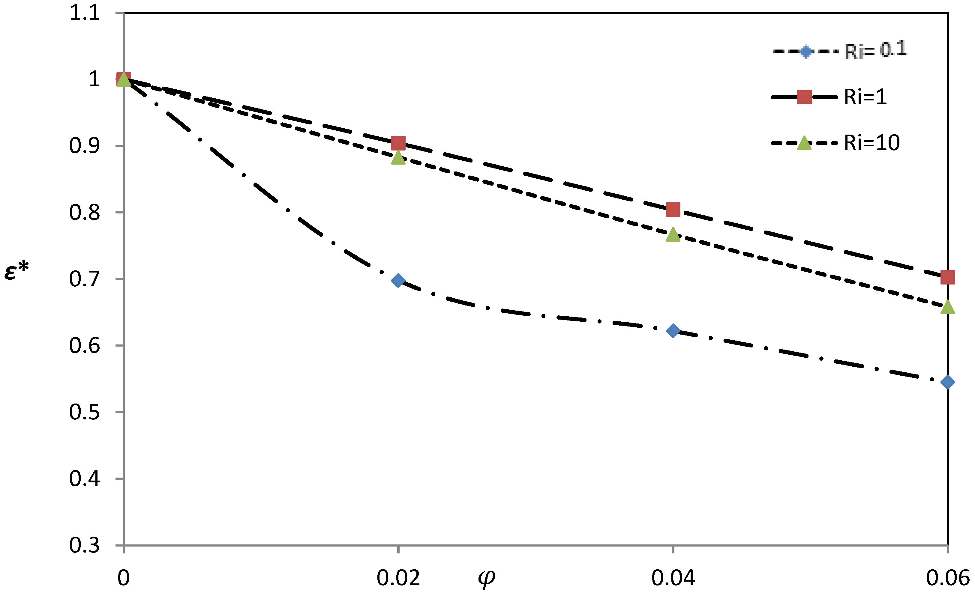
Figure 12 presents the variation of the mean Nusselt number for Ri = 0.1, 1, and 10 at Re = 100 and AR = 0.5. For Ri = 1, the natural and forced convections were equivalent, hence forcing the nanofluid through the horizontal leg of the channel, which can destroy the natural convective currents and hence minimize the mean Nusselt number. For the forced convection dominance condition, Ri = 0.1, the forced nanofluid would reinforce the convection and increase the mean Nusselt number. However, with the natural convection dominance condition, Ri = 10, the mean Nusselt number was at its maximum. Similarly, the total entropy generation behaved with the Richardson number as shown in Figure 13 by giving an indication of the dominance of the heat transfer irreversibility along with a high effect of the viscous force. Figure 14 demonstrates mostly constant improvement and linear drawbacks of thermal performance with increasing values of the Richardson number and the nanoparticles volume fraction, respectively. The effect of the nanoparticles volume fraction was studied in a normalized fashion as in Figure 15, Figure 16 and Figure 17. These figures show rapid heat transfer augmentation, and mostly linear entropy generation increased with φ at high Richardson numbers whereas, in general, the nanoparticles increased the thermodynamic irreversibility as shown in Figure 17.
4.3. Effect of the Aspect Ratio
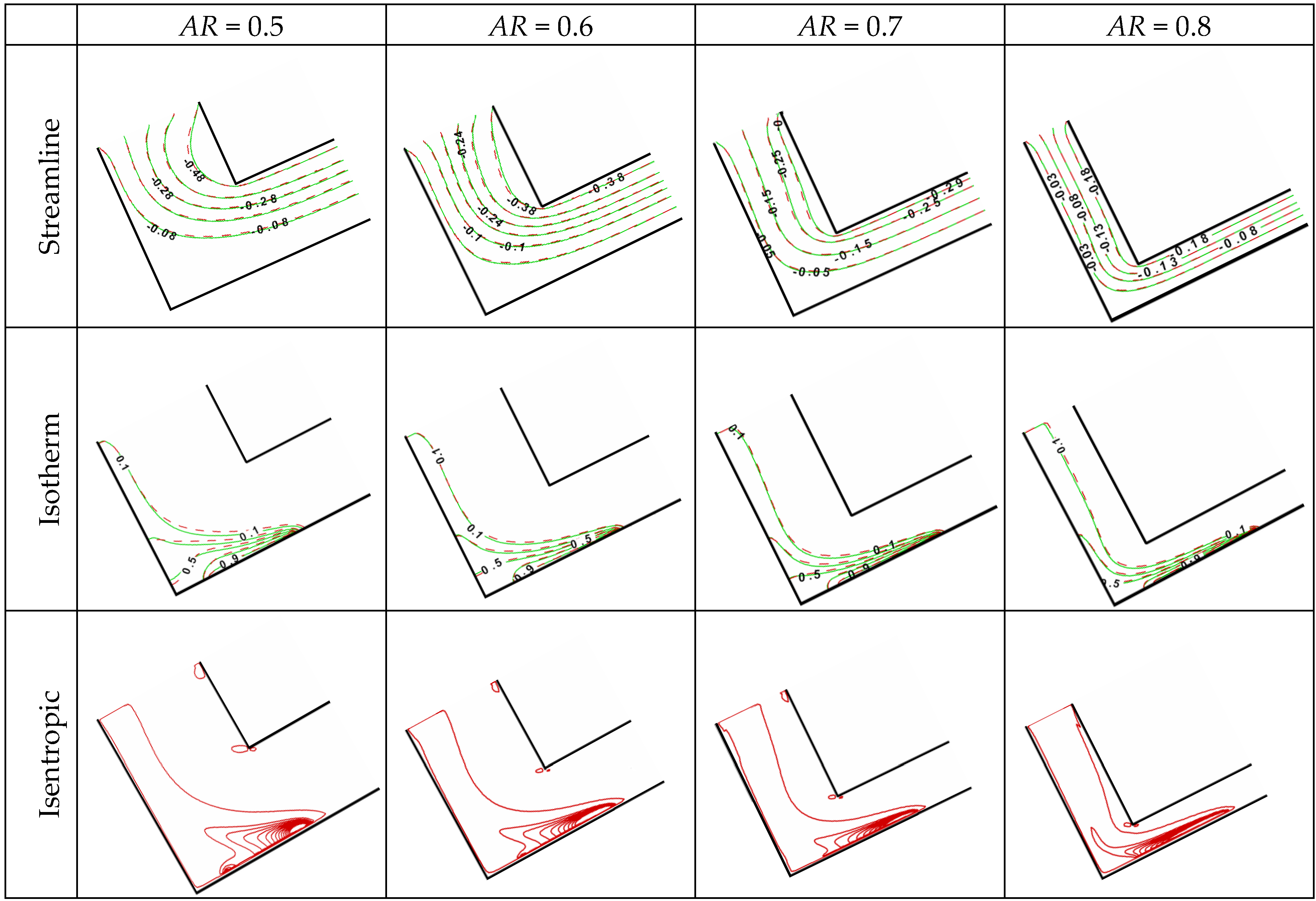
The effect of the channel size was studied by varying the aspect ratio AR from 0.5 to 0.8 for Re = 100 and Ri = 1. Figure 18 shows that at AR = 0.5, when the streamlines turned 90° through the horizontal leg, they arched far away from the lower wall of the horizontal channel. When AR increased, the space available for the fluid flow decreased and thus, the streamlines became narrower and occupied most of the entire channel. Following the streamline tendency, the isotherms were intensified close to the heater element at the lower wall of the horizontal channel. The isentropic lines also concentrated violently close to the heater element.
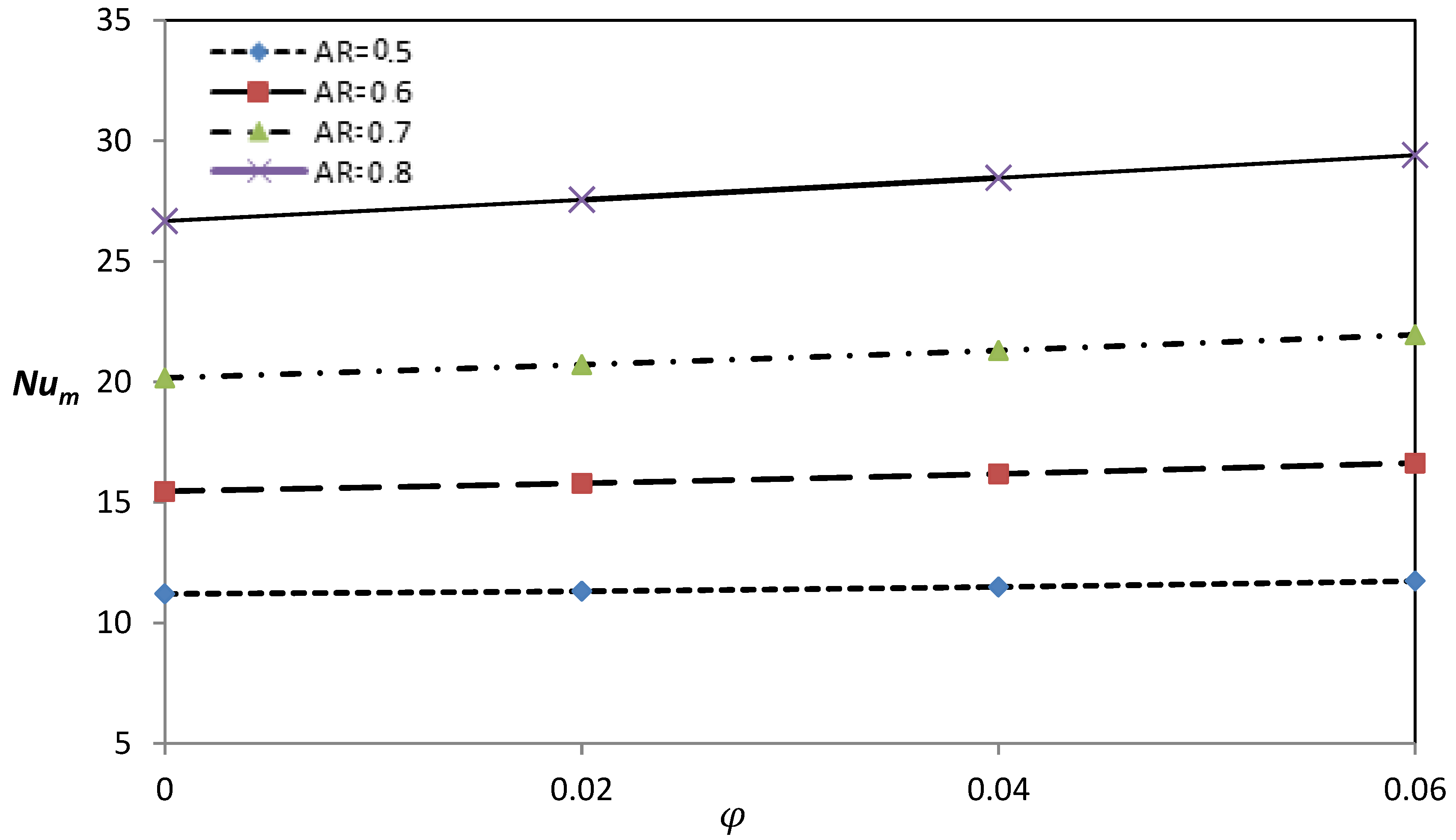
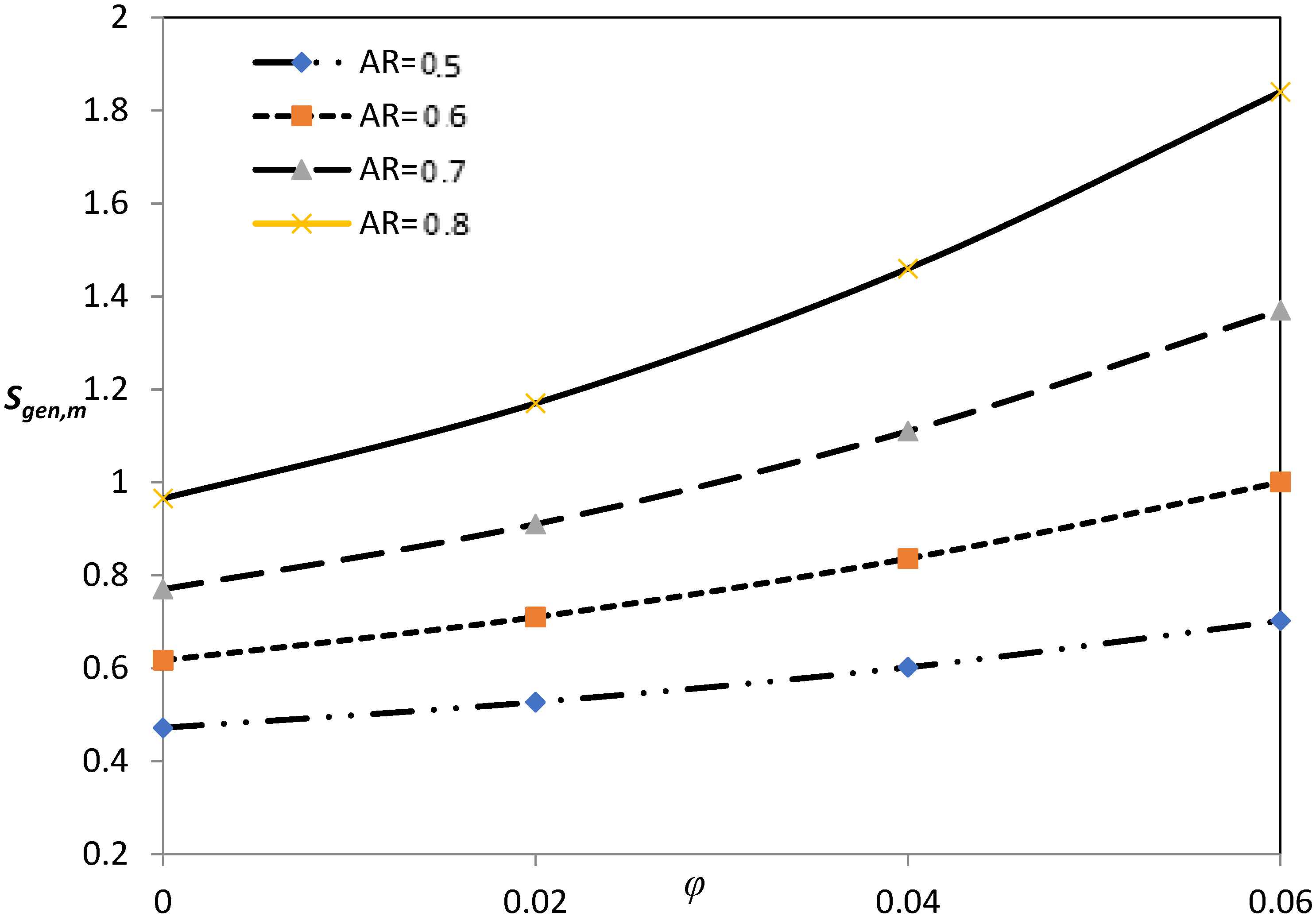
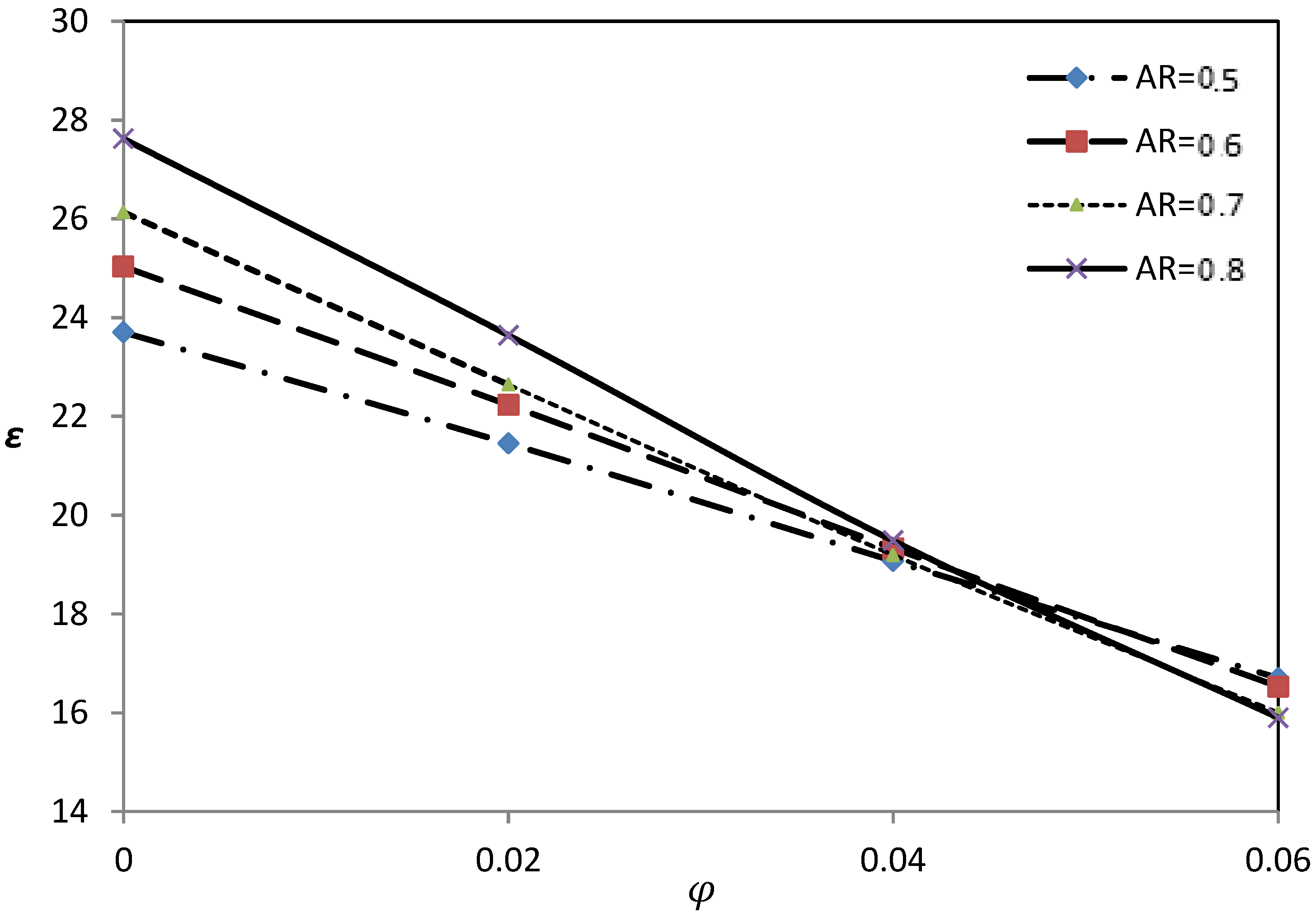
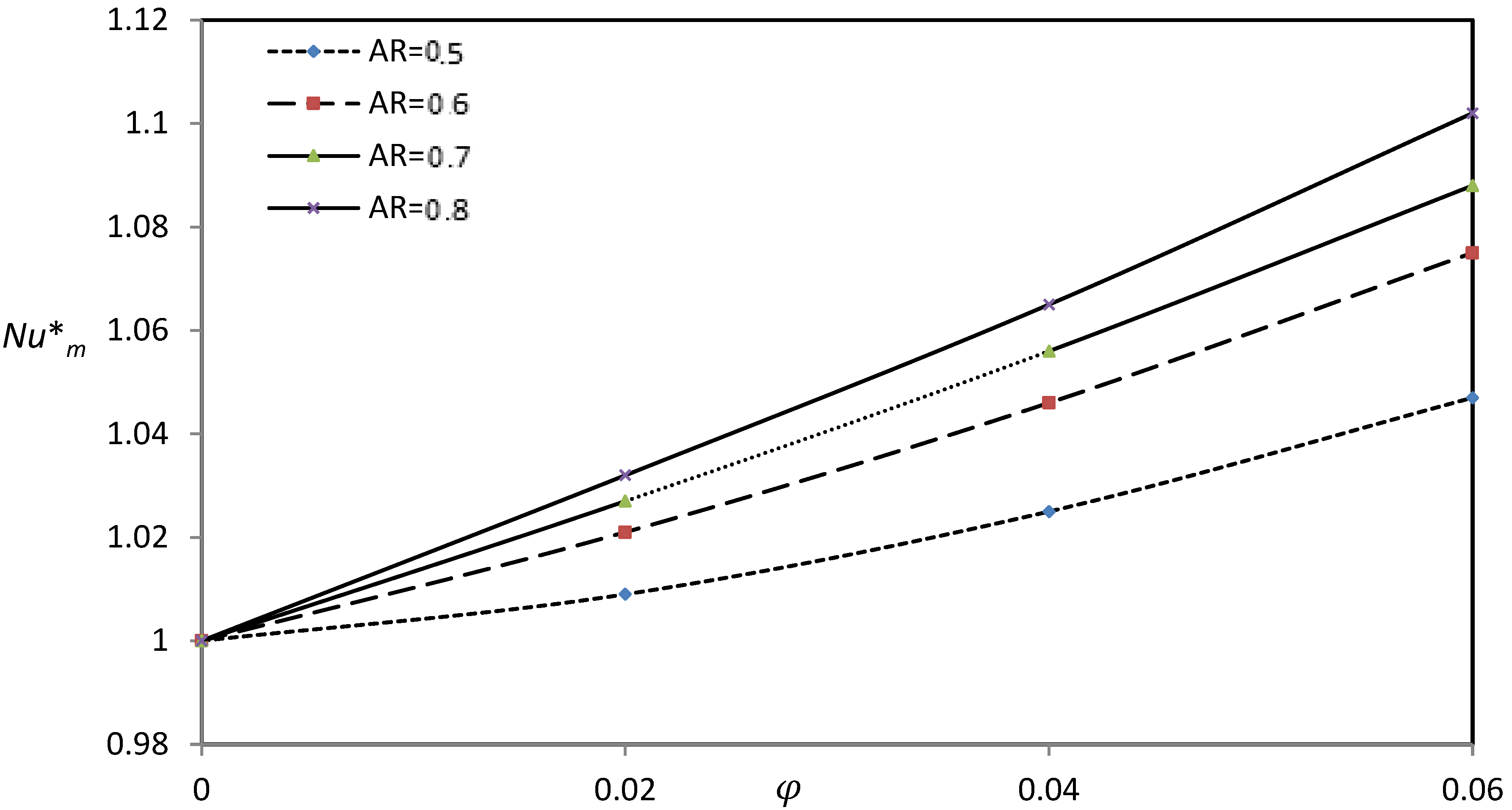
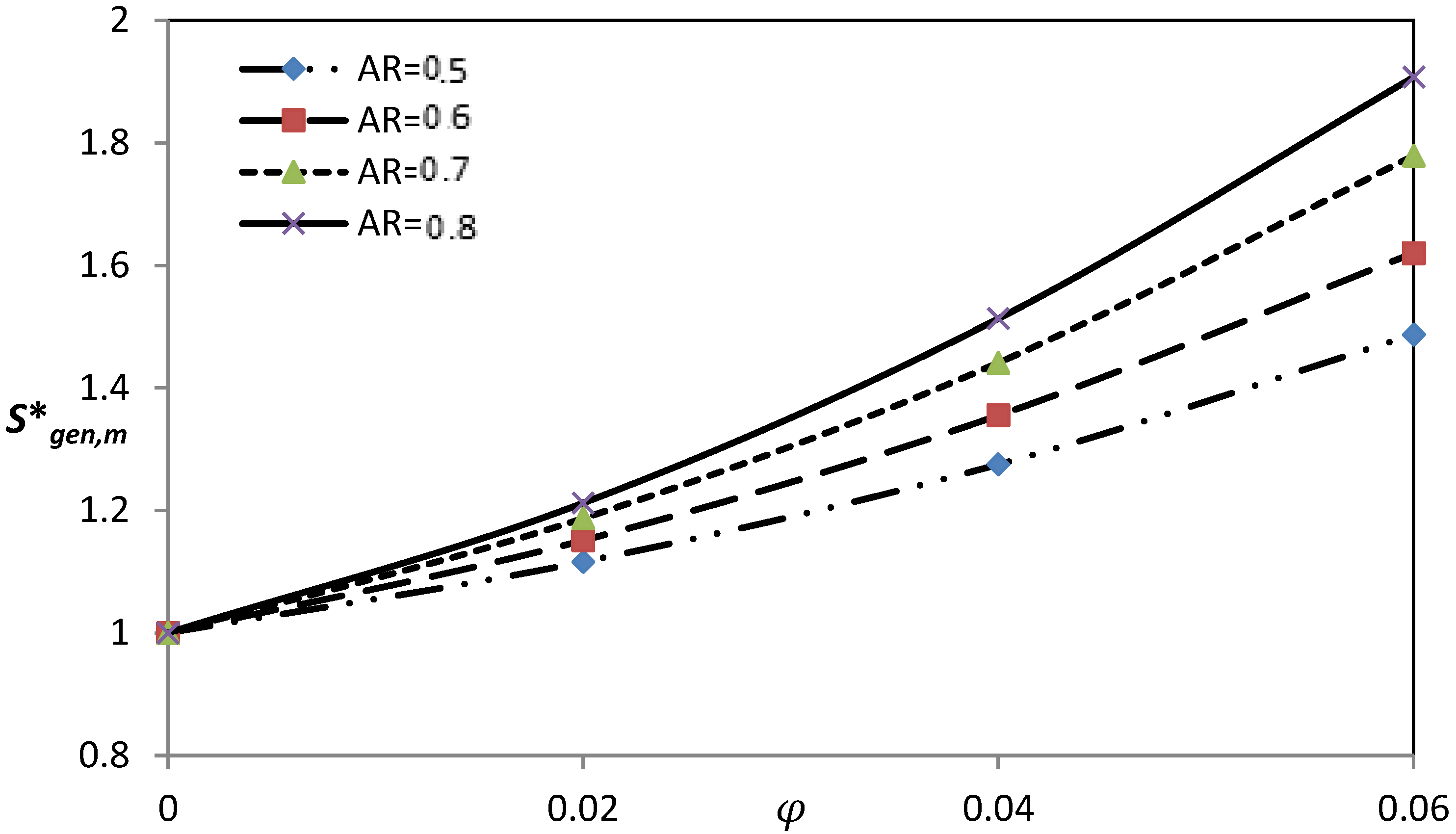
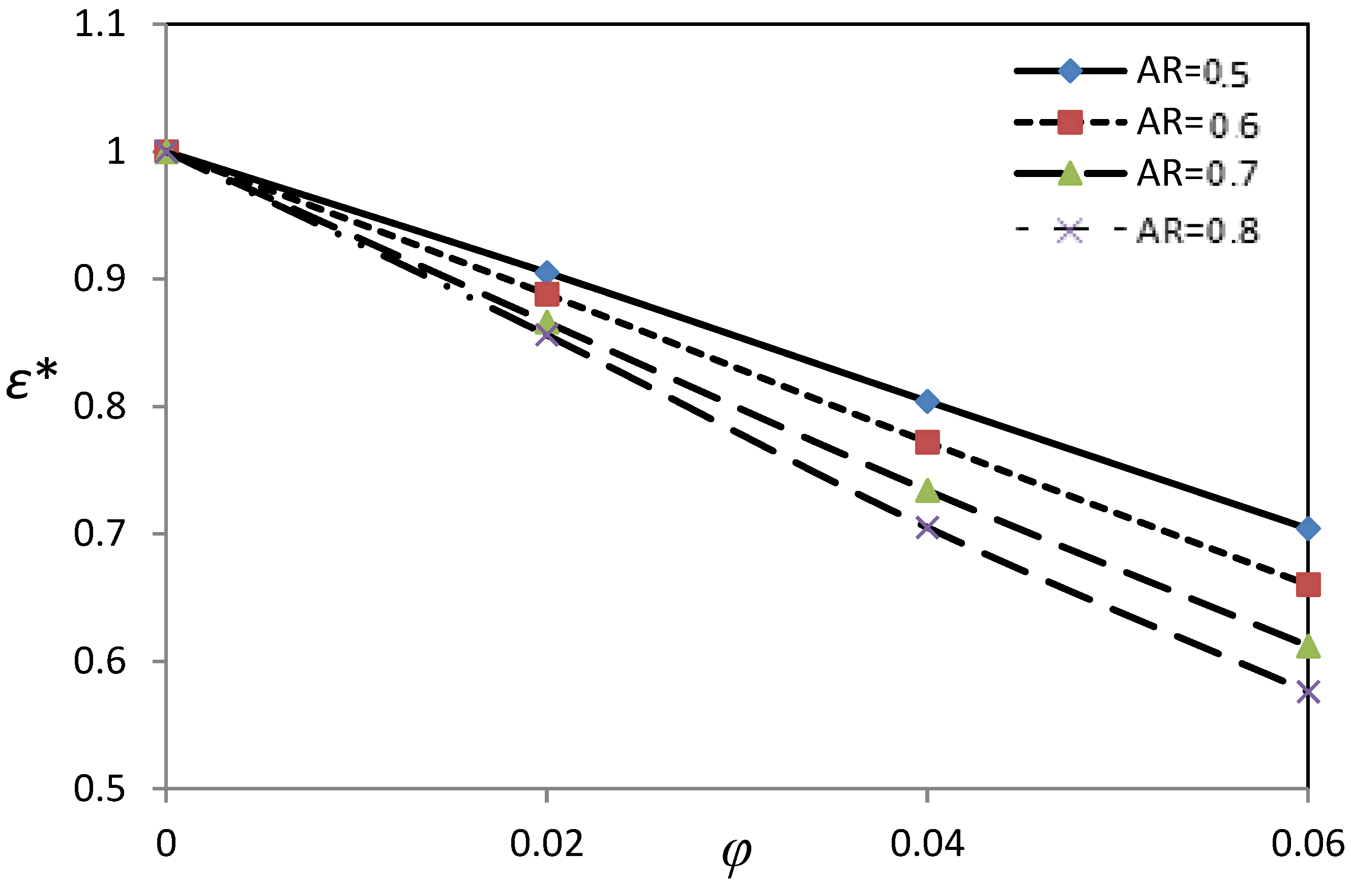
Figure 19 shows that the mean Nusselt number was directly proportional to the aspect ratio. This was due to the augmentation of the forced convection gained by the decreasing flow area when AR increased. Hence, increasing AR reinforced the flow intensity and the transferred heat transfer; as such, the heat transfer and the fluid friction irreversibility increased accordingly. This effect is clearly visible in Figure 20, where the rate of entropy generation increased with an increase of AR. In Figure 19 and Figure 20, the nanofluid increased both the mean Nusselt number and the entropy generation at any aspect ratio. Figure 21 suggests that there was competition between the effects of AR and φ, where reducing the channel passages (i.e., increasing AR) enhanced the utility of the thermal energy with respect to the thermodynamic irreversibility—this was true up to φ ≅ 0.045. Beyond this value, the effect of increasing φ overcame the effect of AR. This can be drawn from the conversion of curves shown in Figure 21.
5. Conclusions
Mixed convection of an Ag-water nanofluid in an inclined L-shaped channel was numerically studied using the finite volume method. By keeping the inclination of the channel fixed, the Reynolds number, Richardson number, aspect ratio, and the nanoparticles volume fraction were varied, giving the following conclusions:
The Nusselt number increased with an increase of the Reynolds number Re, while entropy generation decreased drastically when Re increased from Re = 50 to 100. However, this decrease slowed down when Re increased beyond 100. When Re = 100, the convective heat transfer and the entropy generation rate were at their maxima at higher values of the Richardson number and at their minima when the value of the Richardson number equal to unity. The narrower L-shaped channel (i.e., higher aspect ratio) augmented the convective heat transfer and the rate of entropy generation. According to the ε criterion, which was defined in this study as the ratio of the mean Nusselt number to the total entropy generation rate, the best utilization of the convective heat transfer could be attained at higher values of the Reynolds and Richardson numbers. High aspect ratios also gave the best ε values, but up to a certain limit of the nanoparticles volume fraction (φ = 0.045). Beyond this limit, the lower aspect ratio gave the best ε value.
Generally, the mean Nusselt number and the rate of entropy generation increased with increasing values of the nanoparticles volume fraction while, conversely, the utility of the convective heat transfer (ε criterion) decreased with the increase of the nanoparticles volume fraction.
Author Contributions
T.A. and M.A.I. designed the model and the computational framework and analyzed the data. T.A. performed the calculations. M.A.I. and A.J.C. wrote the manuscript with input from all authors. A.J.I. and I.P. conceived the study and were in charge of overall direction and planning.
Funding
This research was funded by UEFISCDI grant number PN-III-P4-ID-PCE-2016-0036.
Acknowledgments
The work of Ioan Pop was supported from the grant PN-III-P4-ID-PCE-2016-0036, UEFISCDI, Romania. The authors wish also to express their very sincere thanks to the very competent Reviewers for the very good comments and suggestions.
Conflicts of Interest
There is no conflict of interest.
Nomenclature
| AR | aspect ratio (H/L) |
| g | gravitational field (m s−2) |
| H | inner side of the channel (m) |
| k | thermal conductivity (W m−1 K−1) |
| L | outer side of the channel (m) |
| Nu | average Nusselt number |
| Ri | Richardson number |
| Re | Reynolds number |
| Sl | entropy generation rate (WK−1·m−3) |
| Sgen,m | total entropy generation rate |
| T | temperature (K) |
| P | pressure (Nm−2) |
| u, U | velocity component in x-axis (m·s−1, dimensionless) |
| v, V | velocity component in y-axis (m·s−1, dimensionless) |
| x, y | Cartesian coordinates (m) |
| X, Y | Cartesian coordinates (dimensionless) |
| Greek symbols | |
| α | thermal diffusivity (m2·s−1) |
| β | coefficient of thermal expansion t (K−1) |
| ε | performance criterion () |
| φ | volume fraction |
| λ | inclination of the channel (30°) |
| µ | dynamic viscosity (N·s·m−2) |
| θ | temperature (dimensionless) |
| ρ | density (kg·m−3) |
| Ψ | stream function (dimensionless) |
| Subscripts | |
| c | cold |
| f | fluid |
| h | hot |
| l | local |
| m | mean |
| nf | nanofluid |
| s | solid nanoparticles |
| Superscripts | |
| * | dimensionless |
References
- Shah, R.K.; London, A.L. Laminar flow forced convection in ducts. In Advances in Heat Transfer; Irvine, T.F., Hartnett, J.P., Eds.; Academic Press: New York, NY, USA, 1978. [Google Scholar]
- Sunden, B.; Skoldheden, T. Heat transfer and pressure drop in a new type of corrugated channels. Int. Commun. Heat Mass Transf. 1985, 12, 559–566. [Google Scholar] [CrossRef]
- Abu-Mulaweh, H.I. A review of research on laminar mixed convection flow over backward- and forward-facing steps. Int. J. Therm. Sci. 2003, 42, 897–909. [Google Scholar] [CrossRef]
- Young, T.J.; Vafai, K. Convective cooling of a heated obstacle in a channel. Int. J. Heat Mass Transf. 1998, 41, 3131–3148. [Google Scholar] [CrossRef]
- Mousavi, S.S.; Hooman, K.; Mousavi, S.J. Genetic algorithm optimization for finned channel performance. Appl. Math. Mech. 2007, 28, 1597–1604. [Google Scholar] [CrossRef]
- Yang, M.-H.; Yeh, R.-H.; Hwang, J.-J. Forced convection in a channel with transverse fins. Int. J. Numer. Methods Heat Fluid Flow 2012, 22, 306–322. [Google Scholar] [CrossRef]
- Mezrhab, A.; Amraqui, S.; Abid, C. Modeling of combined surface radiation and natural convection in a vented ‘‘T” form cavity. Int. J. Heat Fluid Flow 2010, 31, 83–92. [Google Scholar] [CrossRef]
- Kasaeipoor, A.; Ghasemi, B.; Aminossadati, S.M. Convection of Cu-water nanofluid in a vented T-shaped cavity in the presence of magnetic field. Int. J. Therm. Sci. 2015, 94, 50–60. [Google Scholar] [CrossRef]
- Biserni, C.; Rocha, L.A.O.; Stanescu, G.; Lorenzini, E. Constructal H-shaped cavities according to Bejan’s theory. Int. J. Heat Mass Transf. 2007, 50, 2132–2138. [Google Scholar] [CrossRef]
- Bejan, A.; Lorente, S. Design with Constructal Theory; Wiley: Hoboken, NJ, USA, 2008. [Google Scholar]
- Marcondes, F.; Maliska, C.R. Treatment of the inlet boundary conditions in natural-convection flow in open-ended channels. Numer. Heat Transf. B 1999, 35, 317–345. [Google Scholar]
- Zhu, B.; Chi, X.; Dennis, R.A.; Chyu, M.K.; Bryden, M.A.; Shih, T.I.-P. Internal cooling inside an L-shaped duct with pin-fin turbulators under rotating and non-rotating conditions with and without sand particles. In Proceedings of the GT 2007 ASME Turbo Expo 2007: Power for Land, Sea and Air, Montreal, QC, Canada, 14–17 May 2007. [Google Scholar]
- Pardeshi, I.A. Flow and heat transfer in an L-shaped cooling passage with ribs and pin fins for the trailing edge of a gas-turbine vane and blade. Master’s Thesis, Purdue University, West Lafayette, IN, USA, 2013. [Google Scholar]
- Armaghani, T.; Kasaeipoor, A.; Alavi, N.; Rashidi, M.M. Numerical investigation of water-alumina nanofluid natural convection heat transfer and entropy generation in a baffled L-shaped cavity. J. Mol. Liquids 2016, 223, 243–251. [Google Scholar] [CrossRef]
- Arani, A.A.A.; Maghsoudi, A.Z.; Niroumand, A.H.; Derakhshani, S.M.E. Study of nanofluid natural convection in an inclined L-shaped cavity. Sci. Iran. F 2013, 20, 2297–2305. [Google Scholar]
- Mojumder, S.; Saha, S.; Rahman, M.R.; Rahman, M.M.; Rabbi, K.M.; Ibrahim, T. Numerical study on mixed convection heat transfer in a porous L-shaped cavity. Eng. Sci. Technol. Int. J. 2017, 20, 272–282. [Google Scholar] [CrossRef]
- Choi, S.U.S.; Eastman, J.A. Enhancing thermal conductivity of fluids with nanoparticles. In Proceedings of the ASME International Mechanical Engineering Congress & Exposition, San Francisco, CA, USA, 12–17 November 1995. [Google Scholar]
- Tiwari, R.K.; Das, M.K. Heat transfer augmentation in a two-sided lid-driven differentially heated square cavity utilizing nanofluids. Int. J. Heat Mass Transf. 2007, 50, 2002–2018. [Google Scholar] [CrossRef]
- Mahmoudi, A.H.; Shahi, M.; Talebi, F. Effect of inlet and outlet location on the mixed convective cooling inside the ventilated cavity subjected to an external nanofluid. Int. Commun. Heat Mass Transf. 2010, 37, 1158–1173. [Google Scholar] [CrossRef]
- Shahi, M.; Mahmoudi, A.H.; Talebi, F. Numerical study of mixed convective cooling in a square cavity ventilated and partially heated from the below utilizing nanofluid. Int. Commun. Heat Mass Transf. 2010, 37, 201–213. [Google Scholar] [CrossRef]
- Nasrin, R.; Alim, M.A.; Chamkha, A.J. Numerical simulation of non-Darcy forced convection through a channel with nonuniform heat flux in an open cavity using nanofluid. Numer. Heat Transf. A 2013, 64, 820–840. [Google Scholar] [CrossRef]
- Bahlaoui, A.; Raji, A.; Hasnaoui, M.; Naïmi, M. Mixed convection heat transfer enhancement in a vented cavity filled with a nanofluid. J. Appl. Fluid Mech. 2016, 9, 593–604. [Google Scholar] [CrossRef]
- Santra, A.K.; Chakraborty, S.S.N. Study of heat transfer due to laminar flow of copper–water nanofluid through two isothermally heated parallel plates. Int. J. Therm. Sci. 2009, 48, 391–400. [Google Scholar] [CrossRef]
- Heshmati, A.; Mohammed, H.A.; Darus, A.N. Mixed convection heat transfer of nanofluids over backward facing step having a slotted baffle. Appl. Math. Comput. 2014, 240, 368–386. [Google Scholar] [CrossRef]
- Al-Aswadi, A.A.; Mohammed, H.A.; Shuaib, N.H.; Campo, A. Laminar forced convection flow over a backward facing step using nanofluids. Int. Commun. Heat Mass Transf. 2010, 37, 950–957. [Google Scholar] [CrossRef]
- Bejan, A. A study of entropy generation in fundamental convective heat transfer. J. Heat Transf. 1979, 101, 718–725. [Google Scholar] [CrossRef]
- Bejan, A. Second-law analysis in heat and thermal design. Adv. Heat Transf. 1982, 15, 1–58. [Google Scholar]
- Bejan, A. Entropy Generation Minimization; CRC Press: Boca Raton, FL, USA; New York, NY, USA, 1996. [Google Scholar]
- Mukhopadhyay, A. Analysis of entropy generation due to natural convection in square enclosures with multiple discrete heat sources. Int. Commun. Heat Mass Transf. 2010, 37, 867–872. [Google Scholar] [CrossRef]
- Ovando-Chacon, G.E.; Ovando-Chacon, S.L.; Prince-Avelino, J.C. Entropy generation due to mixed convection in an enclosure with heated corners. Int. J. Heat Mass Transf. 2012, 55, 695–700. [Google Scholar] [CrossRef]
- Mahmud, S.; Islam, A.K.M.S. Laminar free convection and entropy generation inside an inclined wavy enclosure. Int. J. Therm. Sci. 2003, 42, 1003–1012. [Google Scholar] [CrossRef]
- Cho, C.-C.; Chen, C.-L.; Chen, C.-K. Natural convection heat transfer performance in complex-wavy-wall enclosed cavity filled with nanofluid. Int. J. Therm. Sci. 2012, 60, 255–263. [Google Scholar] [CrossRef]
- Esmaeilpour, M.; Abdollahzadeh, M. Free convection and entropy generation of nanofluid inside an enclosure with different patterns of vertical wavy walls. Int. J. Therm. Sci. 2012, 52, 127–136. [Google Scholar] [CrossRef]
- Kashani, S.; Ranjbar, A.A.; Mastiani, M.; Mirzaei, H. Entropy generation and natural convection of nanoparticle-water mixture (nanofluid) near water density inversion in an enclosure with various patterns of vertical wavy walls. Appl. Math. Comput. 2014, 226, 180–193. [Google Scholar] [CrossRef]
- Varol, Y.; Oztop, H.F.; Koca, A. Entropy production due to free convection in partially heated isosceles triangular enclosures. Appl. Therm. Eng. 2008, 28, 1502–1513. [Google Scholar] [CrossRef]
- Ismael, M.A.; Armaghani, T.; Chamkha, A.J. Conjugate heat transfer and entropy generation in a cavity filled with a nanofluid saturated porous media and heated by a triangular solid. J. Taiwan Inst. Chem. Eng. 2016, 59, 138–151. [Google Scholar] [CrossRef]
- Chamkha, A.; Ismael, M.; Kasaeipoor, A.; Armaghani, T. Entropy generation and natural convection of CuO-Water nanofluid in C-shaped cavity under magnetic field. Entropy 2016, 18, 50. [Google Scholar] [CrossRef]
- Latife, B.E.; Mehmet, S.E.; Birsen, S.; Yalcum, M.M. Entropy generation during fluid flow between two parallel plates with moving bottom plate. Entropy 2003, 5, 506–518. [Google Scholar]
- Mahmud, S.; Fraser, R.A. Thermodynamic analysis of flow and heat transfer inside channel with two parallel plates. Exergy Int. J. 2003, 2, 140–146. [Google Scholar] [CrossRef]
- Makinde, O.D.; Osalusi, E. Second law analysis of laminar flow in a channel filled with saturated porous media. Entropy 2005, 7, 148–160. [Google Scholar] [CrossRef]
- Narusawa, U. The second law analysis of mixed convection in rectangular ducts. Heat Mass Transf. 2001, 37, 197–203. [Google Scholar] [CrossRef]
- Syeda, H.T.; Shohel, M. Entropy generation in a vertical concentric channel with temperature dependent viscosity. Int. Commun. Heat Mass Transf. 2002, 29, 907–918. [Google Scholar]
- Makinde, O.D.; Gbolagade, A.W. Second law analysis of incompressible viscous flow through an inclined channel with isothermal walls. Rom. J. Phys. 2005, 50, 923–930. [Google Scholar]
- Makinde, O.D.; Eegunjobi, A.S. Effects of convective heating on entropy generation rate in a channel with permeable walls. Entropy 2013, 15, 220–233. [Google Scholar] [CrossRef]
- Abu-Nada, E. Investigation of entropy generation over a backward facing step under bleeding conditions. Energy Convers. Manag. 2008, 49, 3237–3242. [Google Scholar] [CrossRef]
- Abu-Nada, E. Entropy generation due to heat and fluid flow in backward facing step flow with various expansion ratios. Int. J. Exergy 2006, 3, 419–435. [Google Scholar] [CrossRef]
- Izadi, S.; Armaghani, T.; Ghasemi-Asl, R.; Chamkha, A.J.; Molana, M. A comprehensive review on mixed convection of nanofluids in various shapes of enclosures. Powder Technol. 2019, 343, 880–907. [Google Scholar] [CrossRef]
- Chamkha, A.J.; Rashad, A.M.; Mansour, M.A.; Armaghani, T.; Ghalambaz, M. Effects of heat sink and source and entropy generation on MHD mixed convection of a Cu-water nanofluid in a lid-driven square porous enclosure with partial slip. Phys. Fluids 2017, 29, 052001. [Google Scholar] [CrossRef]
- Chamkha, A.J.; Rashad, A.M.; Armaghani, T.; Mansour, M.A. Effects of partial slip on entropy generation and MHD combined convection in a lid-driven porous enclosure saturated with a Cu–water nanofluid. J. Therm. Anal. Calorim. 2018, 132, 1291–1306. [Google Scholar] [CrossRef]
- Chamkha, A.J.; Rashad, A.M.; Armaghani, T.; Mansour, M.A. Entropy generation and MHD natural convection of a nanofluid in an inclined square porous cavity: Effects of a heat sink and source size and location. Chin. J. Phys. 2018, 56, 193–211. [Google Scholar]
- Alsabery, A.; Armaghani, T.; Chamkha, A.J.; Sadiq, M.; Hashim, I. Effects of two-phase nanofluid model on convection in a double lid-driven cavity in the presence of a magnetic field. Int. J. Numer. Methods Heat Fluid Flow 2018, 28, 1613–1647. [Google Scholar] [CrossRef]
- Alsabery, A.; Armaghani, T.; Chamkha, A.J.; Sadiq, M.; Hashim, I. Conjugate heat transfer of Al2O3–water nanofluid in a square cavity heated by a triangular thick wall using Buongiorno’s two-phase model. J. Therm. Anal. Calorim. 2019, 135, 161–176. [Google Scholar] [CrossRef]
- Esmaeili, H.; Armaghani, T.; Abedini, A.; Pop, I. Turbulent combined forced and natural convection of nanofluid in a 3D rectangular channel using two-phase model approach. J. Therm. Anal. Calorim. 2018. [Google Scholar] [CrossRef]
- Fard, M.H.; Esfahany, M.N.; Talaie, M.R. Numerical study of convective heat transfer of nanofluids in a circular tube two-phase model versus single-phase model. Int. Commun. Heat Mass Transf. 2010, 37, 91–97. [Google Scholar] [CrossRef]
- Brinkman, H. The viscosity of concentrated suspensions and solutions. J. Chem. Phys. 1952, 20, 571. [Google Scholar] [CrossRef]
- Oztop, H.F.; Abu-Nada, E. Numerical study of natural convection in partially heated rectangular enclosures filled with nanofluids. Int. J. Heat Fluid Flow 2008, 29, 1326–1336. [Google Scholar] [CrossRef]
- Patankar, S. Numerical Heat Transfer and Fluid Flow; CRC Press: Boca Raton, FL, USA, 1980. [Google Scholar]
Figure 1.
The physical domain and coordinates system.

Figure 2.
A uniform grid distribution of the physical domain.

Figure 3.
Comparison with Kasaeieepoor et al.’s study [8] at a Re = 100 with a T-shaped vented cavity.
Figure 3.
Comparison with Kasaeieepoor et al.’s study [8] at a Re = 100 with a T-shaped vented cavity.

Figure 4.
Streamlines, isotherms, and isentropic lines for Ri = 1 and AR = 0.5, solid lines for φ = 0, and dashed lines for φ = 0.06.
Figure 4.
Streamlines, isotherms, and isentropic lines for Ri = 1 and AR = 0.5, solid lines for φ = 0, and dashed lines for φ = 0.06.

Figure 5.
Variation of the mean Nusselt number with Re and φ for Ri = 1.0 and AR = 0.5.

Figure 6.
Variation of the total rate of entropy generation with Re and φ for Ri = 1.0 and AR = 0.5.
Figure 6.
Variation of the total rate of entropy generation with Re and φ for Ri = 1.0 and AR = 0.5.

Figure 7.
Variation of the ε criterion with Re and φ for Ri = 1.0 and AR = 0.5.

Figure 8.
Variation of the normalized mean Nusselt number with Re and φ at Ri = 1 and AR = 0.5.

Figure 9.
Variation of the normalized total entropy generation with Re and φ at Ri = 1 and AR = 0.5.
Figure 9.
Variation of the normalized total entropy generation with Re and φ at Ri = 1 and AR = 0.5.

Figure 10.
Variation of the normalized ε criterion with Re and φ at Ri = 1 and AR = 0.5.

Figure 11.
Streamlines, isotherms, and isentropic lines for Re = 100 and AR = 0.5, solid lines for φ = 0, and dashed lines for φ = 0.06.
Figure 11.
Streamlines, isotherms, and isentropic lines for Re = 100 and AR = 0.5, solid lines for φ = 0, and dashed lines for φ = 0.06.

Figure 12.
Variation of the mean Nusselt number with Ri and φ for Re = 100 and AR = 0.5.

Figure 13.
Variation of the total entropy generation with Ri and φ for Re = 100 and AR = 0.5.

Figure 14.
Variation of the ε criterion with Ri and φ for Re = 100 and AR = 0.5.

Figure 15.
Variation of the normalized mean Nusselt number with Ri and φ at Re = 100 and AR = 0.5.

Figure 16.
Variation of the normalized total entropy generation with Ri and φ at Re = 100 and AR = 0.5.
Figure 16.
Variation of the normalized total entropy generation with Ri and φ at Re = 100 and AR = 0.5.

Figure 17.
Variation of the normalized ε criterion with Ri and φ at Re = 100 and AR = 0.5.

Figure 18.
Streamlines, isotherms, and isentropic lines for Re = 100, solid lines for φ = 0, and dashed lines for φ = 0.06.
Figure 18.
Streamlines, isotherms, and isentropic lines for Re = 100, solid lines for φ = 0, and dashed lines for φ = 0.06.

Figure 19.
Variation of the mean Nusselt number with AR and φ for Re = 100 and Ri = 1.

Figure 20.
Variation of the total entropy generation with AR and φ for Re = 100 and Ri = 1.

Figure 21.
Variation of the ε criterion with AR and φ for Re = 100 and Ri = 1.

Figure 22.
Variation of the normalized mean Nusselt number with AR and φ for Re = 100 and Ri = 1.

Figure 23.
Variation of the normalized total entropy generation with AR and φ for Re = 100 and Ri = 1.
Figure 23.
Variation of the normalized total entropy generation with AR and φ for Re = 100 and Ri = 1.

Figure 24.
Variation of the normalized ε criterion with AR and φ for Re = 100 and Ri = 1.


Table 1.
Thermo-physical properties of the used nanoparticles and the base fluid.
| Thermo-Physical Properties | Ag-Nanoparticle | Water (Base Fluid) |
|---|---|---|
| ρ (kg·m−3) | 10,500 | 997.1 |
| Cp (J·kg−1·K−1) | 235 | 4179 |
| k (W·m−1·K−1) | 430 | 0.613 |
| Β × 10−5 (K−1) | 5.1 | 21 |
| µ × 10−4 (kg·m−1·s−1) | - | 8.9 |
| α × 10−6 (m−1·s−1) | 149 | 0.14 |
Table 2.
Grid independency test for a Richardson number Ri = 1, aspect ratio AR = 0.5, nanoparticles volume fraction φ = 0.04, and angle λ = 30° for two different Reynolds numbers (Re = 50 and 200).
Table 2.
Grid independency test for a Richardson number Ri = 1, aspect ratio AR = 0.5, nanoparticles volume fraction φ = 0.04, and angle λ = 30° for two different Reynolds numbers (Re = 50 and 200).
| Number of Grids | 40 × 40 | 60 × 60 | 80 × 80 | 100 × 100 | 120 × 120 | 140 × 140 | 160 × 160 |
|---|---|---|---|---|---|---|---|
| Re = 50 | 10.953 | 11.134 | 11.228 | 11.285 | 11.331 | 11.331 | 11.331 |
| Re = 200 | 14.847 | 13.372 | 12.760 | 12.475 | 12.324 | 12.324 | 12.324 |
© 2019 by the authors. Licensee MDPI, Basel, Switzerland. This article is an open access article distributed under the terms and conditions of the Creative Commons Attribution (CC BY) license (http://creativecommons.org/licenses/by/4.0/).
Share and Cite
MDPI and ACS Style
Armaghani, T.; Ismael, M.A.; Chamkha, A.J.; Pop, I. Mixed Convection and Entropy Generation of an Ag-Water Nanofluid in an Inclined L-Shaped Channel. Energies 2019, 12, 1150. https://0-doi-org.brum.beds.ac.uk/10.3390/en12061150
AMA Style
Armaghani T, Ismael MA, Chamkha AJ, Pop I. Mixed Convection and Entropy Generation of an Ag-Water Nanofluid in an Inclined L-Shaped Channel. Energies. 2019; 12(6):1150. https://0-doi-org.brum.beds.ac.uk/10.3390/en12061150
Chicago/Turabian StyleArmaghani, Taher, Muneer A. Ismael, Ali J. Chamkha, and Ioan Pop. 2019. "Mixed Convection and Entropy Generation of an Ag-Water Nanofluid in an Inclined L-Shaped Channel" Energies 12, no. 6: 1150. https://0-doi-org.brum.beds.ac.uk/10.3390/en12061150
Note that from the first issue of 2016, this journal uses article numbers instead of page numbers. See further details here.