Hybrid Electric Vehicle: Design and Control of a Hybrid System (Fuel Cell/Battery/Ultra-Capacitor) Supplied by Hydrogen

1
Jeddah Community College, JCC, King Abdulaziz University, Jeddah 21589, Saudi Arabia
2
Analysis and Processing of Electrical and Energy Systems Unit, Faculty of Sciences of Tunis El Manar, PB 2092 Belvedere, Tunisia
Energies 2019, 12(7), 1272; https://0-doi-org.brum.beds.ac.uk/10.3390/en12071272
Submission received: 1 March 2019
/
Revised: 22 March 2019
/
Accepted: 28 March 2019
/
Published: 2 April 2019
(This article belongs to the Special Issue Efficient Electrification Control Systems for Smart Buildings)
Abstract
:Due to its high efficiency and reduced emissions, new zero-emission hybrid electric vehicles have been selected as an attractive challenge for future transport applications. New zero -emission hybrid electric, on the other hand, has some major drawbacks from the complicated charging process. The hybrid electrical fuel cell system is introduced as the main source to intelligently control multi-source activities. An ultra-capacitor system is selected as the energy recovery assistance to monitor the fuel cell’s fast transient and peak power during critical periods. To regulate energy demand and supply, an intelligent energy management system is proposed and tested through several constraints. The proposed approach system aims to act quickly against sudden circumstances related to hydrogen depletion in the prediction of the required fuel consumption basis. The proposed strategy tends to define the proper operating system according to energy demand and supply. The obtained results show that the designed system meets the targets set for the energy management unit by referring to an experimental velocity database.
1. Introduction
Today, fuel cell (FC) vehicles powered by hydrogen are becoming an alternative potential source for transport applications. Uninterrupted power can be provided by proton exchange membrane fuel cell (PEMFC)-vehicles (FCVs) [1,2]. As a result, PEMFC powered by hydrogen becomes an energy carrier of interest to replace traditional fuels. Indeed, PEMFC is emerging as one of the most promising transport applications candidates [3,4]. Because of its lower power and lower starting density, however, as well as its slower response power, PEMFC is still unable to provide ongoing energy to meet demand and is unable to regenerate the required power [5,6,7]. Nevertheless, it is possible to solve the PEMFC drawbacks by adding a secondary energy source such as batteries or ultra-capacitor (UC) or a combination of both [8]. Batteries (BTs) devices are generally characterized by their higher specific energy compared to UCs. In fact, BTs can provide additional power for a long time [9]. However, UCs are inserted to control transient power compared to BTs due to their high power, higher efficiency and longer charging/discharging cycles [10]. Ultra-capacitor is an electrochemical condenser device chosen to deliver average peak power for short durations [11]. The electrical feature of the UC is the same as that of the condensers. The included UC consists of an electrical double layer of non-porous materials containing transition metal oxides, nitrides and polymers (such as pseudo-capacitors). The electronic power interface is the integration of the power source with the power converter motor. The power converters are actually similar to a DC–DC converter (such as a chopper) [12]. Methanol and propane supply hydrogen gas from a biological process and a reform of hydrocarbons [13]. The fuel cell was selected as a potential candidate for converting hydrogen into electricity. However, it may raise concerns (such as efficiency, costs and constraints). The efficiency of hydrogen may depend on system configuration, design and selection of components [14]. The main concerns are reconsidered in the cooperation between sources and in the optimization of energy demand. To do this, the energy management unit is included as a solution of interest to control the demand for the required average power. The main concerns about the energy management unit, however, are the efficacy of using the control method. In addition, in its configuration and application, EMS in Hybrid Electrical System (HES) faces some challenges. The HES challenges are discussed in different works to provide the community as a whole with knowledge and information. The authors, for example, proposed a hybrid energy management unit (PEMFC–BT). In order to compensate for power fluctuations, the proposed system uses energy storage to supply an electric vehicle. Whereas, Azib et al. [15] suggested a hybrid electric vehicle (PEMFC–BT–UC) that tends to inter-source cooperation. To manage and supply the required energy, an efficient energy management unit has been proposed. The presented EMS is aimed at providing and optimizing electrical load [16,17]. Zhan et al. [18] discuss an energy management unit selected for a grid-applied PEMFC/Ultra hybrid condenser. Whereas in [19,20] a hybrid energy management unit (PEMFC–BT–UC) was proposed by Odeim, Thounthong et al. to optimize and control the average power demand. Since we are convinced that the approach systems presented still do not allow the units to be properly monitored and managed, this document expands the previous studies on disadvantages by developing and designing a zero-emission hybrid electric vehicle unit using an energy management unit. To provide an efficient flow of power distribution, the proposed approach is used. We are developing an effective real-time energy management platform for smart to deliver and control energy demand. Indeed, a given real load profile is used to evaluate and investigate the developed design, integration, PEMFC, BT and UC dedicated to transport application. A multi-input single-output model is prosed and discussed. Briefly, the contribution of this work is gathered in the presence of an accurate management strategy in the evaluation and modeling of a new zero-emission hybrid electric vehicle.
The rest of this article is organized as follows: Review and literature contributions; the section on new zero-emissions hybrid electrical system (HES) focuses on fuel cell–BT–UC systems and equipment design; the section on energy management describes the proposed energy management unit; the finding and results section is devoted to the analysis of simulation results as well as the system cost study and the concluding remarks are discussed in the conclusion and future work section.
2. Literature Review and Contributions
Several works have been presented in the literature using multiple energy sources, using various new zero-emission hybrid electric vehicles. The proposed configurations were reviewed to demonstrate that the energy supplied to the electric charge is sufficient depending on the demand or load power. In other cases, the fuel cell and the battery or the battery and UC consume the required energy. Indeed, HES operating conditions can be linked to the average power required, such as start –stop and cruise–acceleration.
2.1. PEMFC–Ultra-Capacitor HES EMS Summary
The UC was introduced in several applications due to its higher density power, fast recharged in a short time and transient response. An alternative (such as improving the efficiency and performance of new zero-emission hybrid electric vehicles) was considered for the purpose of combining the rapid UC transient response with a slow fuel cell transient response. These advantages make the UC suitable as a power source for transport applications. As a result, other studies of PEMFC–UC were conducted. In the following paragraphs, some previous work is reviewed and summarized. For example, Reddy et al. [21] presented a (PEMFC–UC) hybrid system for an electric vehicle. The PEMFC–UC performance was demonstrated through a differential flatness controls. Indeed, the PEMFC fast transition was proved and discussed. The interleaving switching technique included two DC–DC boost converts to minimize the output current ripple. A hybrid system (PEMFC–UC) was suggested by Horrein et al. [22]. A precise EMS was developed to optimize energy demand and control the required average power according to the European drive cycle (NEDC) concept. The proposed strategy was based on a bidirectional load sharing power concept based on a polynomial control technique. The proposed control was compared with a Proportional Integral (PI) controller. The EMS has been shown to be able to control the average power. The results indicated that the PEMFC provides constant DC voltage and current. Furthermore, the proposed system had some drawbacks proven by the resulting graphical fluctuations attributable to the sensors of data acquisition. Meanwhile, a hybrid electric vehicle system (PEMFC–UC) was presented by Karunarathne, Alloui et al. [23,24]. An efficient EMS with a variable transmission gearbox was proposed and discussed in order to optimize and control the average power required. Indeed, the proposed EMS uses two fuzzy logic controllers (FLCs) to cooperate with the included sources. Four inputs such as the hydrogen level, the required speed, the FC–UC required power, and the UC charge state were included in the main FLC. The second FLC, used three input variables, namely the hydrogen level of hydrogen, the fuel cell required current and the UC charging status. Table 1 discusses the purpose studies on the EMS that combine the PEMFC–UC.
2.2. PEMFC–BT HES EMS Summary
Various studies on PEMFC-BT HES have been conducted for several reasons, for example, to allow an engine to start with high current, or to allow operation with low power PEMFC or to achieve high power. by limiting the load. For example, a dedicated PMU (PEMFC–BT) hybrid system was presented by Xiao, Sundstrom et al. [25,26]. The proposed EMS allows the charging between these two sources of energy to be shared. Subsequently, the qualified energy is used on a DC bus. An inverter is developed to convert the DC voltage into AC voltage. Whereas, Hannan et al. [27] proposed a hybrid system (PEMFC–BT) in [27]. The Fuzzy control approach was proposed and discussed. The proposed control deals with monitoring system behavior using four modes of operation. Furthermore, the main target control is to calculate the total power required, taking into account the negative braking power through the accelerator positions, pedal brake. The Fuzzy control generally includes the rules of if–then, but the rules are not visible in the report, and the performance results have not been clear. Meanwhile, the authors reported on the hybrid system (PEMFC–BT) dedicated to the EMS in [28]. The presented control uses dynamic deterministic programming to divide the optimum PEMFC–BT power to minimize a cost function. Depending on the control’s optimal performance, the obtained results focus on the effects of the battery size. Table 2 discusses the purpose studies on EMSs involving FC–UC.
2.3. PEMFC–BT–Ultra-Capacitor HES Summary
To solve the average power required in HES, the BT combined with a UC was considered as energy storage. Indeed, the combination BT–UC was chosen to provide the required power for short periods of maximum power demand, e.g., during acceleration, requiring both high power density. Because the SC is characterized by high power density and low energy density, the idea of adding a battery with the SC is essential, while the battery has low power density and high energy density. For example, Bauman et al. [29] presented a light electric vehicle (PEMFC–BT–UC) hybrid system. An energy management unit using PI regulator was presented and discussed in order to control the average power required. The presented transportation application has been classified in seven logic states. These states are treated through the power duration load, a BT capacity and a three input pedal offset conditions. The obtained control results were compared with the BT source, PEMFC–UC–BT sources, and the drive cycle (ECE-47 test). Only the BT, UC charging, and discharging performances was tested and treated. Martinez et al. [30], proposed a new zero-emission hybrid electric vehicle (PEMFC–BT–UC) hybrid system. The high-power strategies presented were developed and compared. In fact, these control strategies included fuzzy logic control, analyzed predictive control strategy control of equivalent consumption minimization, and control of operating mode. By comparing their performance to 400 kW, the controls presented were processed and discussed. In the meantime, Fathabadi, Jia et al. [31,32] proposed a hybrid system (PEMFC–BT–UC) dedicated to hybrid electric vehicles. An EMS was developed using a Fuzzy Logic (FL) to manage and control the average required power. Indeed, the slow dynamics of the PEMFC and the charging status of the UC were considered. The results obtained show that when the charging status of the BT exceeds the reference value, the PEMFC and UC will provide less power and the reverse. Table 3 discusses the purpose studies on EMSs involving PEMFC–BT–UC Table 3.
2.4. Contributions
Compared to the aforementioned works, we proposed an accurate energy management unit based on decision-making aimed at controlling the energy demand. The proposed EMS aims to distribute the energy flow (PEMFC–BT–UC) among three sources. In fact, this work presents some challenges related to new zero-emission hybrid electric vehicle performance improvement through:
- The presence of an accurate energy equipment control considering the energy demand.
- Rationalizing energy consumption by controlling the operation of new zero-emission hybrid electric vehicles.
- Developing accurate algorithms that reflect the behavior of new zero-emission hybrid electric vehicles against critical transition states such as energy storage and recovery.
- The presence of specific energy equipment was controlled by energy demand.
- New zero-emission hybrid electric vehicle operations tested based on an experiments database.
- Reduction of the fuel consumption rate.
3. System Design
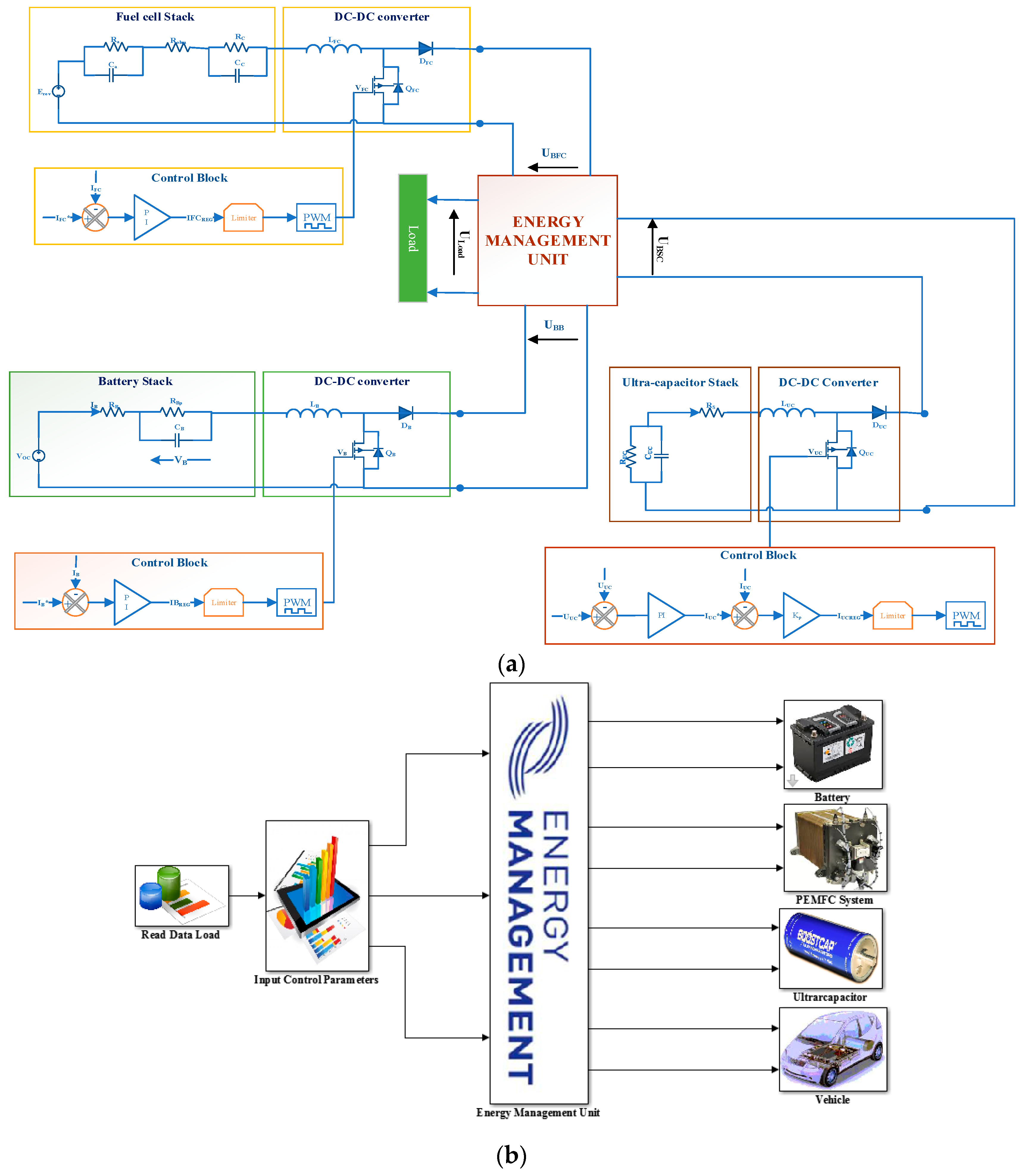
The new zero-emission hybrid electric vehicle powered by PEMFC is investigating a new energy supply consisting of a PEMFC, BT and UC [31]. The PEMFC is used as the primary power supply, and UC and BT are used as backup energy. The exchange power of the PEMFC, BT and UC via a DC bus. To connect the PEMFC to the EMS, a one-way boost converter is included. Although the UC requires a bidirectional amplifier converter to provide the required power when the PEMFC is switched off [33,34]. The included UC is suitable for instant correction and control of the requirements for transient peak power. In particular, the BT serves to boost electrical energy. In addition, during permanent phases such as lack of hydrogen fuel and energy braking, the BT can provide the required power. Two operating modes (PEMFC–UC mode and UC–BT mode are proposed to regulate the distribution power between PEMFC, BT and UC. A new control algorithm for EMS is being developed to achieve high efficiency and optimize the demand for electrical power. Indeed, this algorithm tends to manage and supply load demand through UC charging status and vehicle speed, respectively. A multi-input single-output state space (MISO) is proposed for modeling the HES. Figure 1, which is developed and processed using MATLAB, Simulink, illustrates the presented design. The dynamic HES model consisting of two subsystems are presented. The subsystem-A aims to supply the electrical load and to supervise the power flow distributions without BT. The electrical load receives the required power from both the PEMFC and the UC. In this case, the UC tends to maintain the proper system operation due to its fast and high charging/discharging current. Subsystem B addresses optimizing energy demand when powering off PEMFC. In this case, both the UC and the BT supply the electrical load. This latter was intended to provide efficient functioning under different conditions, respectively controlled by internal resistance and open circuit voltage (VoCV) responsible for identifying variations in the BT state.
The PEMFC mathematical model can be deduced from the electrical circuit equivalent of PEMFC. The FC voltage can therefore be obtained by combining open circuit voltage with activation, ohmic resistance and concentration voltages (Equation (1)) effects [35].
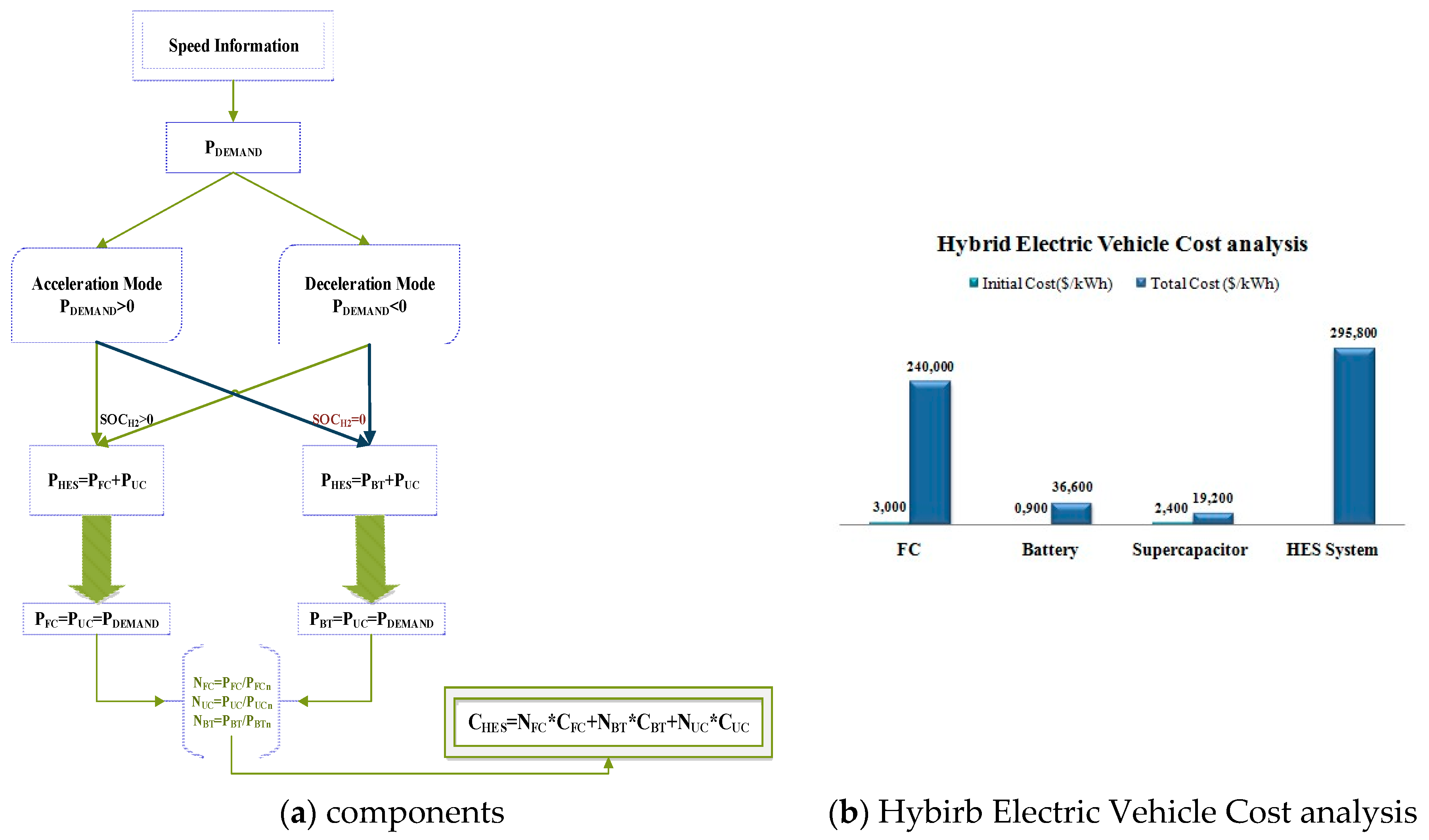
As a function of speed fluctuation as [36], the actual vehicle power demand/the total cost are calculated as
The proposed system is developed as a multi-input single-output system (MISO) (Equation (4)) according to all equations (see Appendix A). Then the HES state space is shown as follows:
4. Energy Management Unit
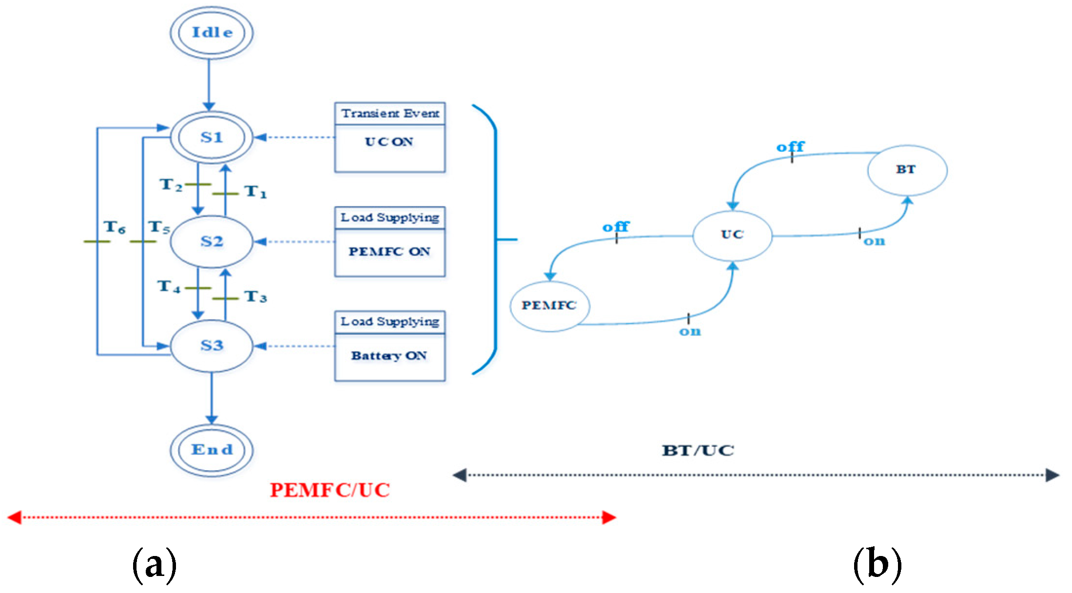
The proposed hybrid electric vehicle scheme provides a flexible and new management system that is controlled by various parameters such as load demand and BT–UC State of charge (SOC). The proposed EMS aims to maintain the system’s proper functioning by properly distributing the flows of energy between the system components. To do this, the proposed control strategy acts to achieve a continuous load under different conditions, based on two operation modes, PEMFC–UC and BT–UC. The PEMFC and BT have both selective sources in this context to ensure the load demand. Indeed, the required energy can be fully realized from the energy emitted by at least one source. The EMS therefore chooses the appropriate component to supply the load demand based on its constraints during the power fluctuation during the basic decision. The system is therefore based on the interaction of all constituent elements by exchanging messages for checking status and activation order. Figure 2 describes the EMS according to the control algorithm with the different operating mode. Through its operational state, the EMS tends to define system performance.
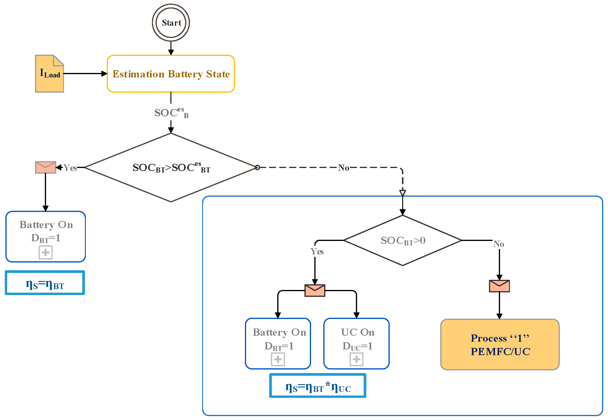
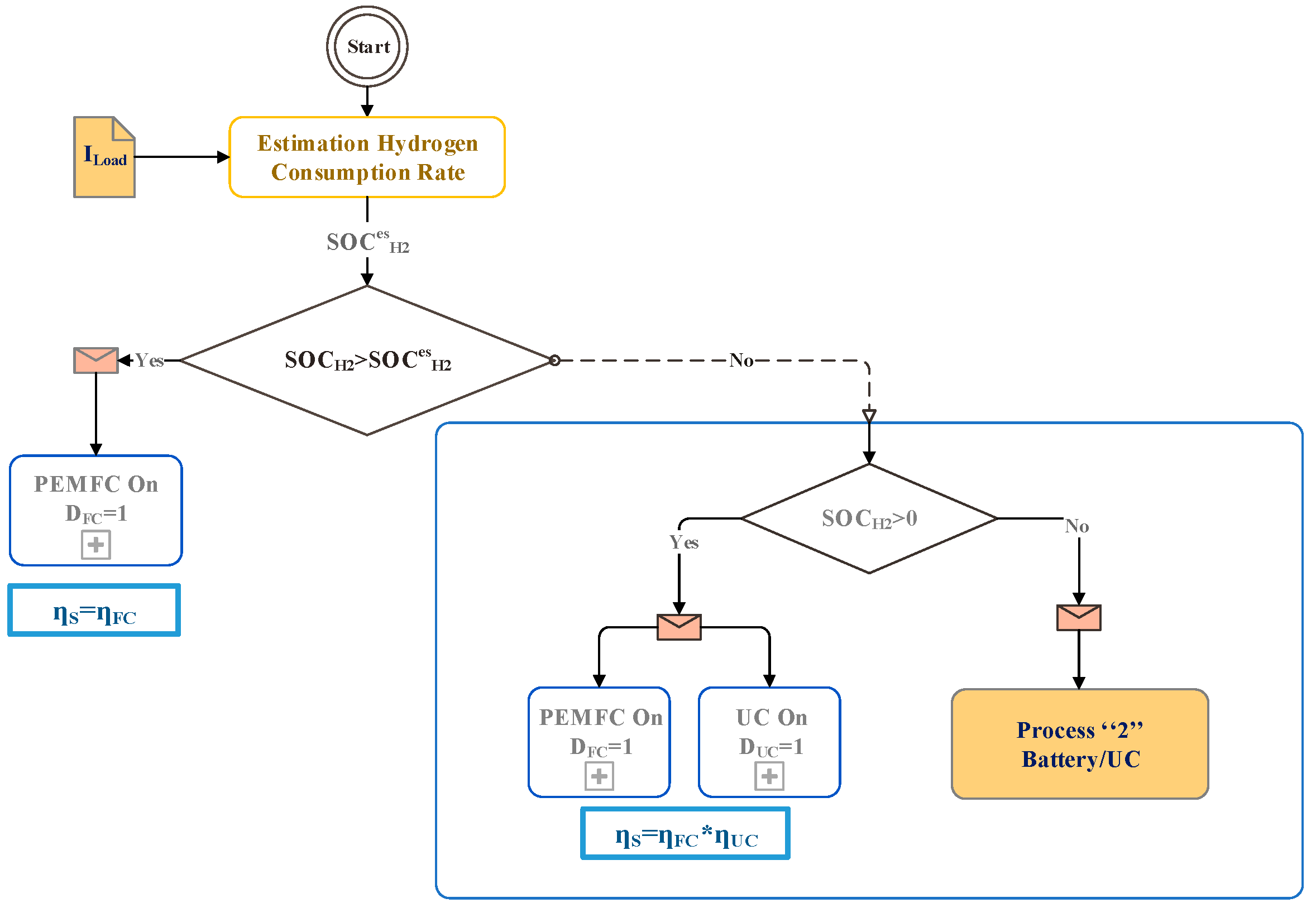
As illustrated in Figure 3 and Figure 4, the EMS uses both the PEMFC and the BT charging state (SoC) to oversee the mode of operation. The hydrogen fuel SOCH2 is used in the proposed algorithm to control the PEMFC state (on/off). In fact, when SOCH2 > SOCnesH2 activates the FC and otherwise turns off. The BT, however, acts as a backup energy unit that holds the charge power when the FC operation appears to be inappropriate due to lack of hydrogen. Even the BT operations are controlled by their state of charges and they are still activated for SOCBT > SOCnesBT and if not, they are OFF. Due to its rapid response, the UC is used to compensate for power demand in transient events. Moreover, in peak power transitions, the UC reacts faster than FC and BT, making the UC activated during all load fluctuation periods. The control algorithm discused begins by checking the load demand while monitoring the effects and constraints of this requirement on the system’s components. The control principle dedicated to the configuration of the Fuel Cell- Battery-Ultra Capacitor (FC-BT-UC) system is given by the Table 4.
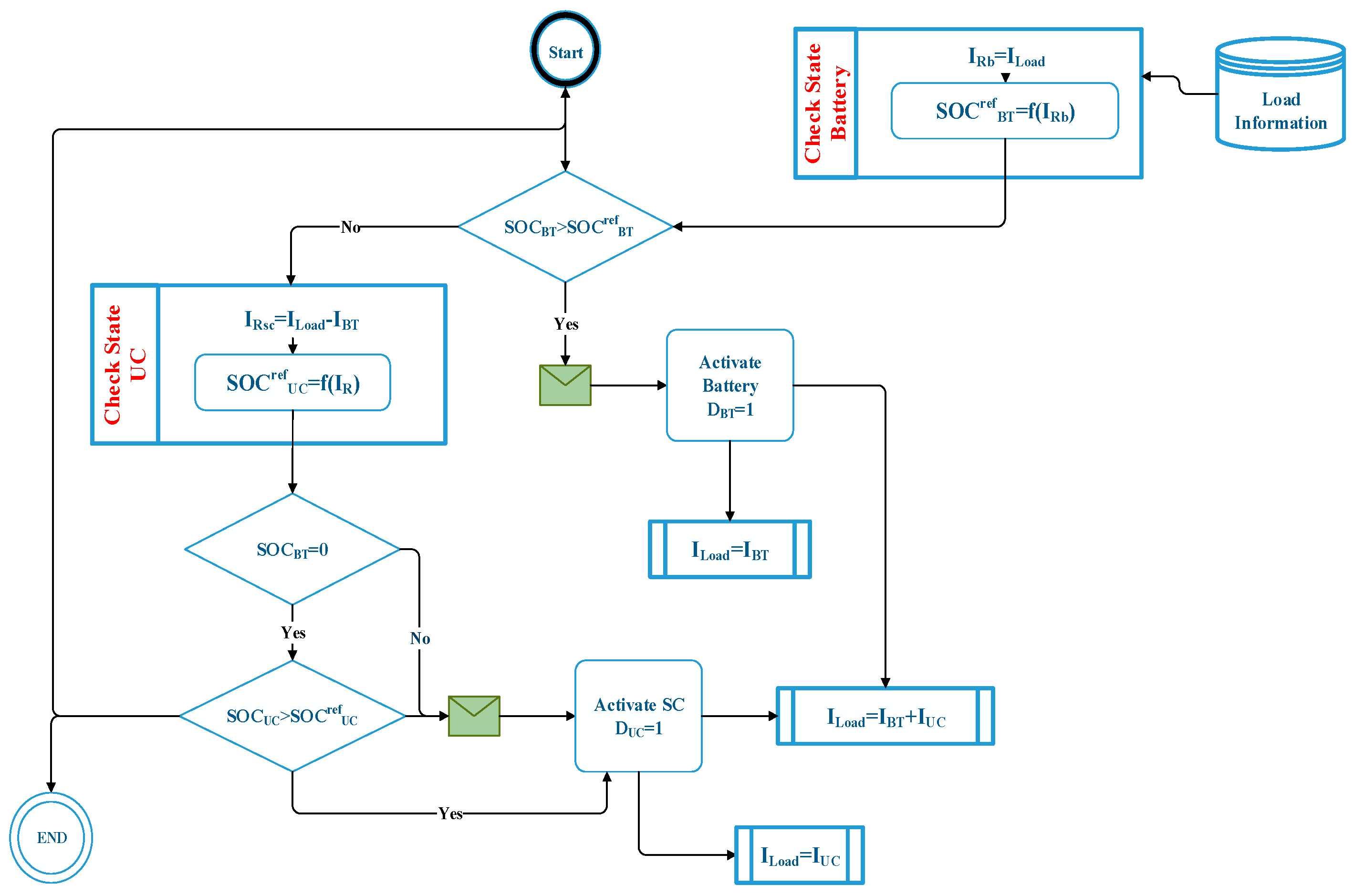
The overall efficiency of the system is evaluated from the selected operating mode based on each component’s activation status. The efficiency of the system is defined as the product of each participating element (the activated element). Table 5 presents the truth table, according to the activation status of each component, of the assumed system efficiency. The control algorithm is described in Figure 5 compared to another system configuration as BT–UC. The control is therefore based on the checking of the status of the charge. The control principle dedicated to the configuration of the Battery-Ultra Capacitor (BT-UC) system is given by the Table 6.
5. System Sizing and Cost Analysis
An accurate sizing system is proposed to carry out the power distribution process and ensure the reliability of the energy management unit. Therefore, to maintain the load requirement, it is a matter of fixing the exact power to be supplied by each source. Thus, the demand for vehicle power is calculated based on the actual velocity value that changes (acceleration, breakdown, and deceleration). However, the power declarations of the components depending on the demand for vehicle power to meet the demand for energy to be in front of any unexpected fluctuation or change. Furthermore, the sizing of the system components is necessary to perform a good techno-economic analysis of the system including the total cost of the system and the components used (see Figure 6). Table 7 below defines the power component required that refers to the average power demand and the power rate of the component (PFCn, PBTn and PUCn).
6. Results and Findings
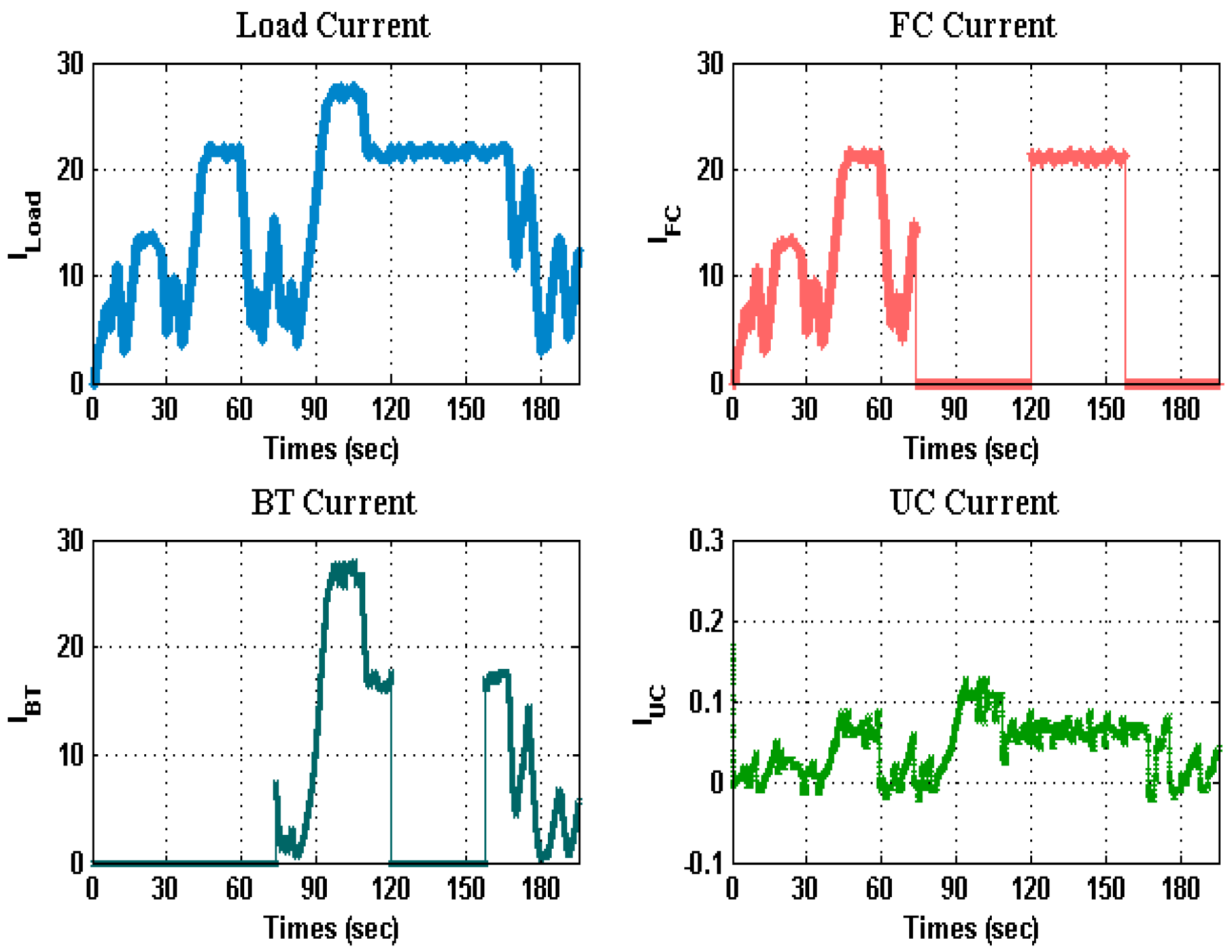
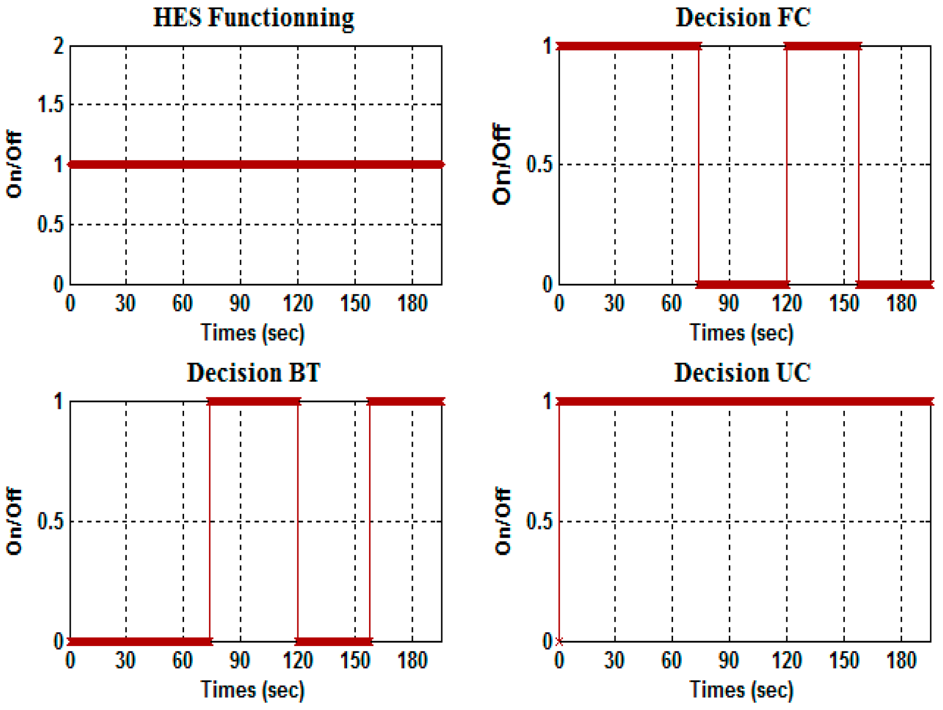
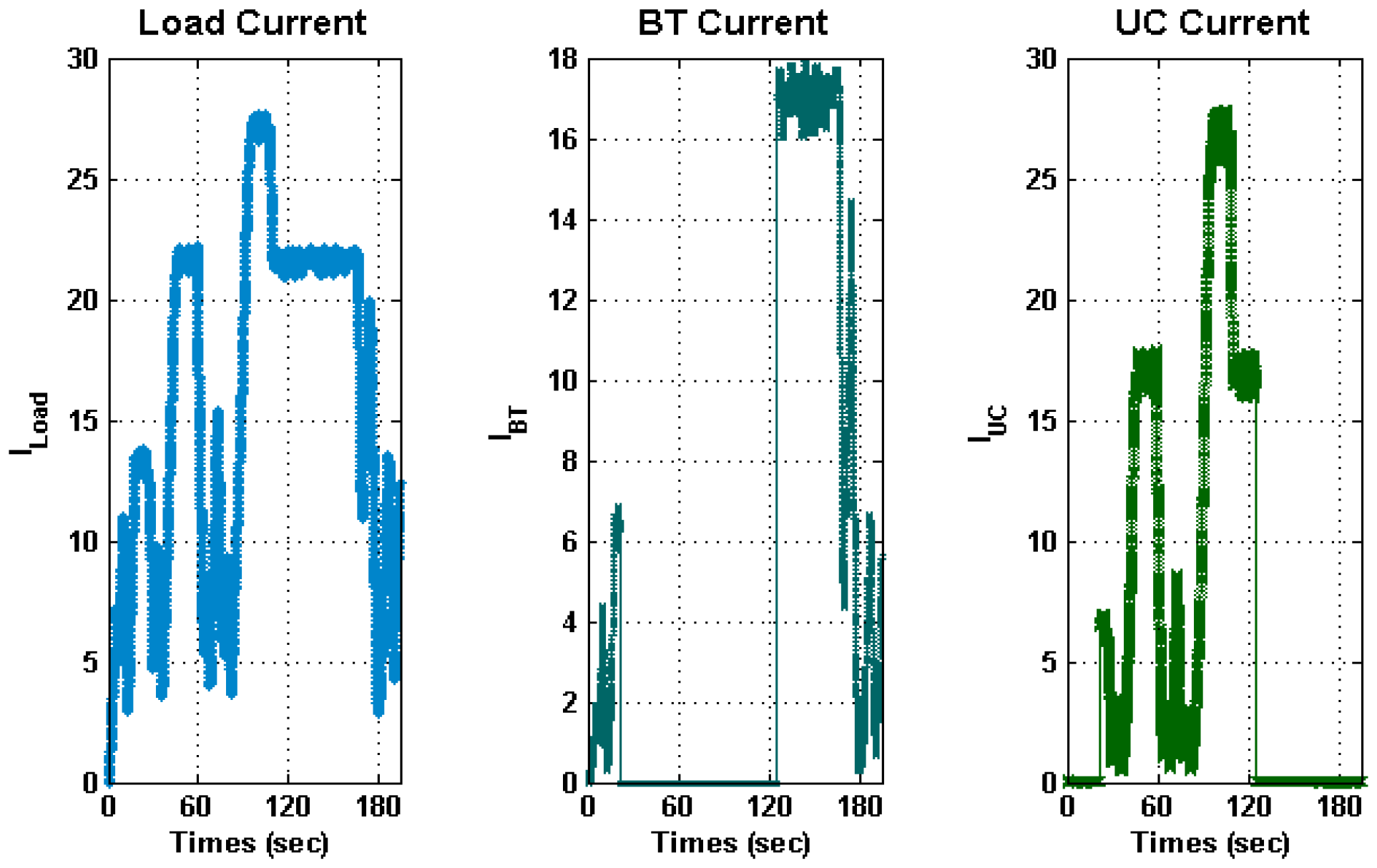
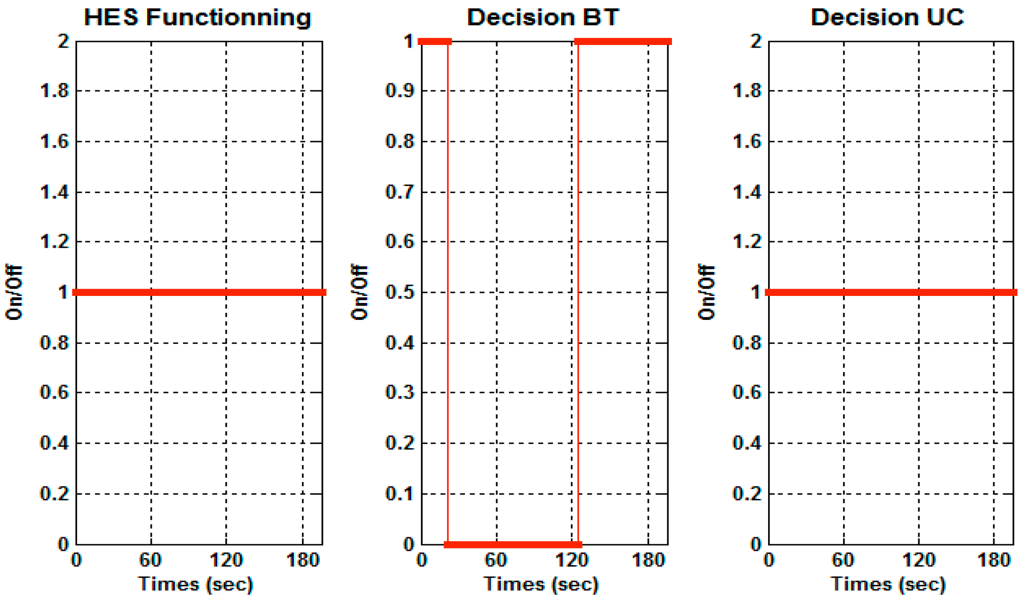
The PEMFC–BT–UC hybrid electrical system’s reliability and efficiency assessment is verified and demonstrated. We have compared our proposed configuration with other BT–UC. Indeed, the Matlab–Simulink environment achieves many simulation results. A two-system configuration is simulated in this section. The parameters of the proposed design for input simulation are given in Table 8. Thus, each of them analyzes and discusses the results obtained separately. Finally, a comparison is developed between the performances of the two proposed configurations. The obtained results by simulating the hybrid electrical system FC–T–UC are shown in the Figure 6. Figure 7 shows the profile of the input load and the affected currents of FC, BT and UC respectively. As seen, during their operation, both FC and BT undergo variations. They change the behavior (ON/OFF) of the system constraint in specific times while the UC is always ready during the transient events to offset the load demand. Therefore, the EMS’s decisions are illustrated in Figure 8. The UC is kept active throughout the simulation test period. Alternatively, however, the FC and BT are activated.
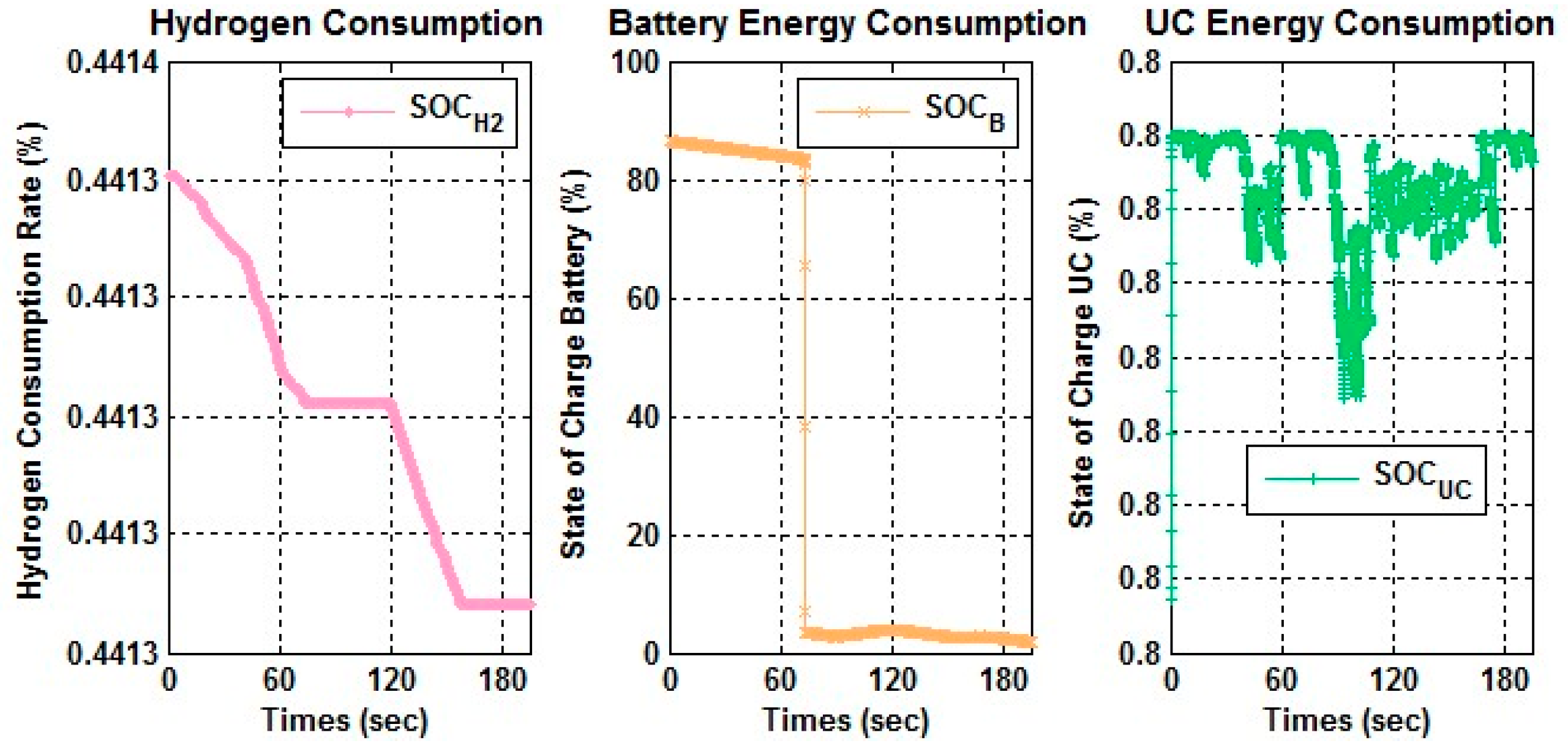
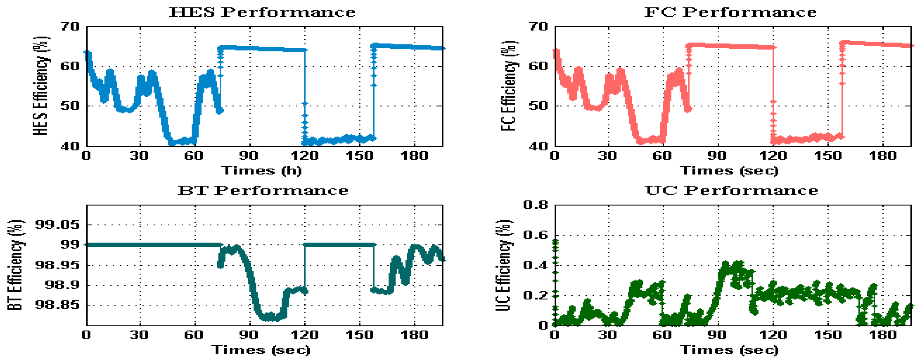
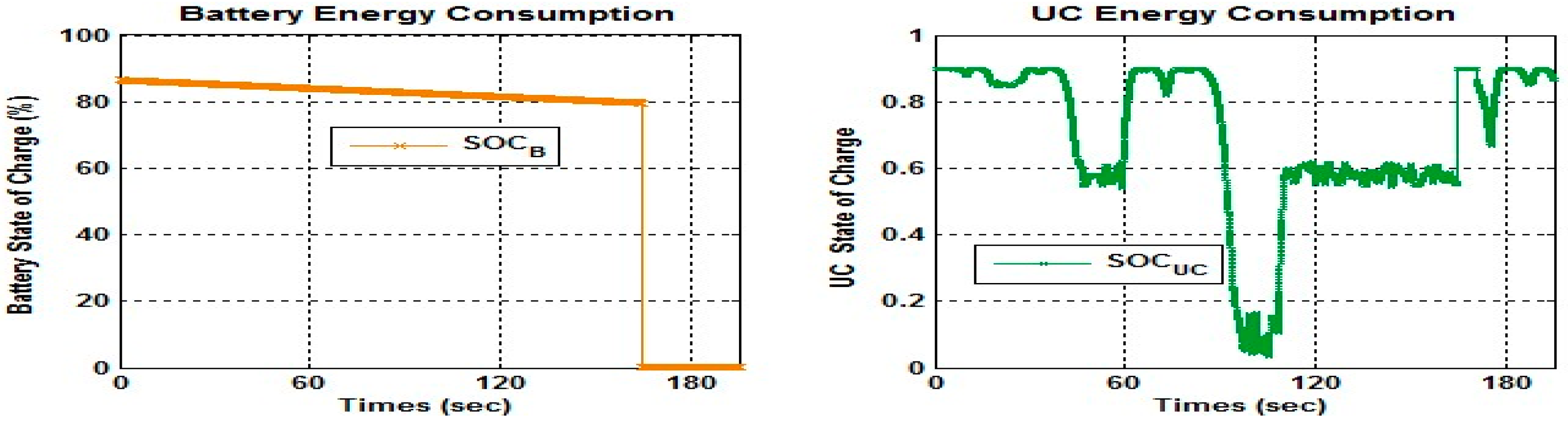
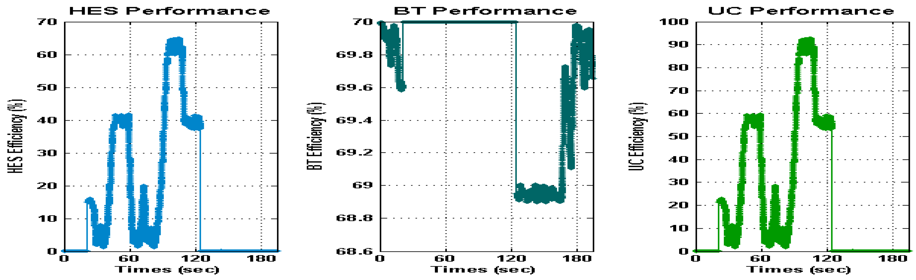
The main parameters considered for controlling the HES system are the consumption rate of hydrogen and BT and UC state of charges. Figure 9 thus describes the fluctuating parameters quoted which may affect the behavior of the system. Therefore, as seen, during the simulation time, all subsystems (PEMFC, BT and UC) were operated alternately. Figure 10 provides the overall efficiency of the HES system. Thus, the maximum value of system efficiency is assumed by 68% with a mean efficiency value of about 54% for FC, 98.85% for BT and 35% for UC. Thus, the maximum value of system efficiency is assumed by 68% with a mean efficiency value of about 54% for FC, 98.85% for BT and 35% for UC. Figure 11 describes the BT and UC currents generated by the given profile. The behaviors of BT and UC are undergoing different changes. In fact, the UC is kept activated throughout the simulation time while the BT operation is fluctuated from ON to OFF based on its constraints essentially related to the system requirements and the state of the fluctuation of electrical load. In this case, the EMS responses are described in Figure 12 from which, respectively, we can deduce the BT and UC activation periods. In this case, of the study, the parameters of HES control are the charging states of BT and UC. Thus, Figure 13 shows the simulated BT–UC state of charges. As noted, the BT state (SOCB) is deeply degraded from 82% to 0.2% while the UC state remains variable from 90% to 10%. The performance of the BT–UC system is described in Figure 14. We can see the mean value of BT efficiency in this system configuration case, about 69.5%, which is lower than the obtained results from the FC–BT–UC configuration. On the contrary, the UC efficiency, presents a significant value compared to the mentioned above configuration. Finally, the obtained results can be seen that the FC–BT–UC system configuration demonstrates its reliability and efficiency in relation to the other configuration. Therefore, if the FC is unable to operate due to lack of hydrogen, the presence of the BT may alleviate the problem of power demand discontinuity.
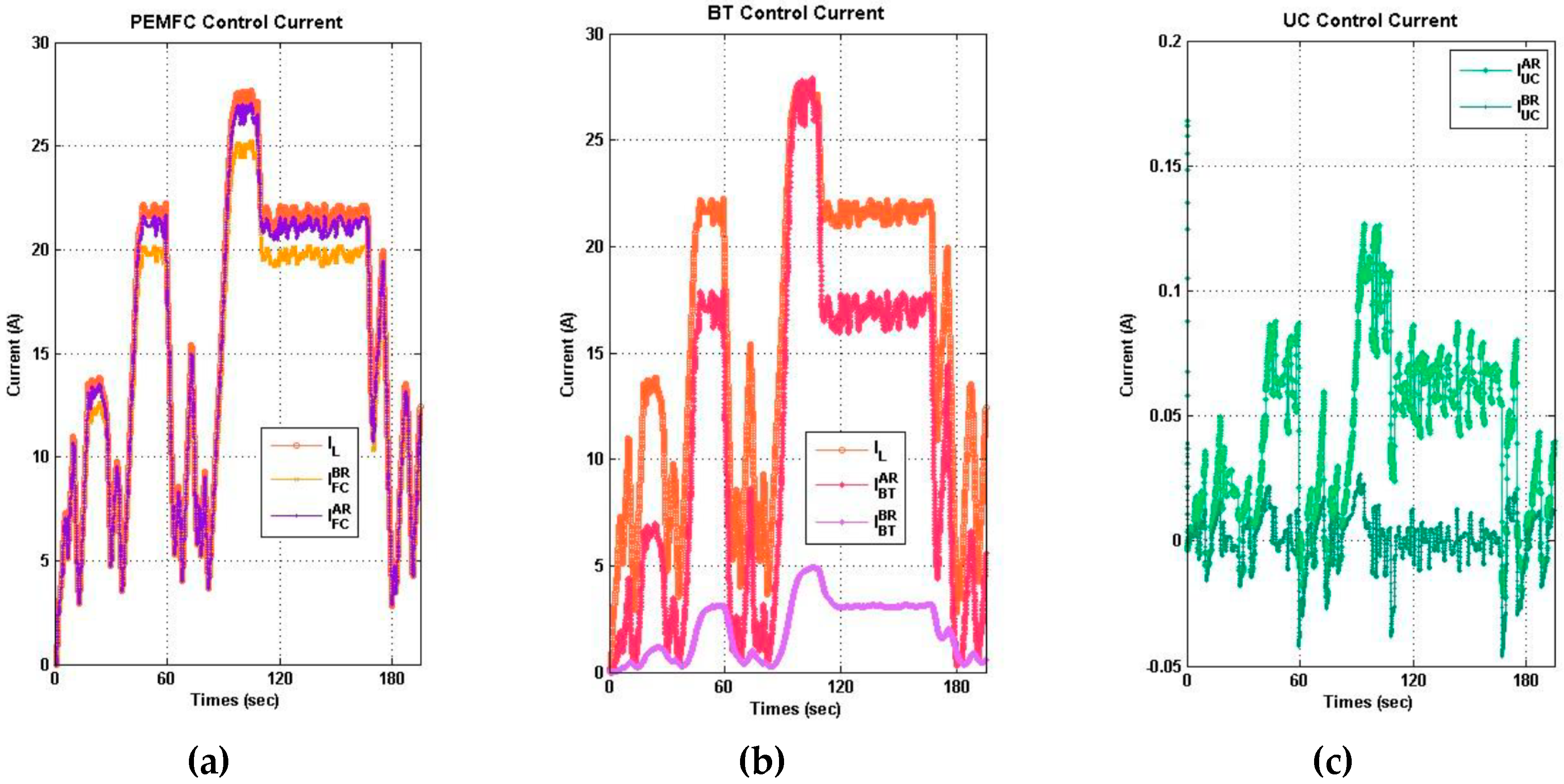
We can confirm that the current curves PEMFC, BT and UC meet the previous equations (Appendix A) based on the results obtained previously. As stated in the previous paragraphs, PEMFC’s excess power was used to charge the BT and UC as recovery energy. The EMS is chosen to control and optimize the average power in the electrical storage system between the UC and the BT depending on the UC current value. Thus, to ensure the output DC converter power stability and precision, a pulse-width modulation (PWM) technique is used for regulation. The EMS is chosen to control and optimize the average power between the UC and the BT depending on the UC current value in the electrical storage system. The PEMFC, UC and BT must be done to control energy demand. Furthermore, a PI controller is selected to control and optimize the average power required by the PEMFC, BT and UC. In Figure 15a–c respectively, the effects of integrating the PI controller into PEMFC, BT and UC are shown. The included PI controller therefore deals to avoid the load level fluctuations of PEMFC. Indeed, the PI provides the average power required by both PEMFC, BT and UC. The FC can generate its maximum power, as shown, and the BT–UC supplements the rest to PEMFC. The UC can provide the average power required because of the BT current limitation. In fact, the average power required is the sum of the load required, the BT supplied and the PEMFC current.
Finally, referring to a few literature works that study the configuration of fuel cell/battery/ultra-capacitor hybrid electric vehicles as [19,36], our work provides an improvement in system management as its components are operated alternately and in coordination to meet the demand for load. On the other hand, the originality of the presented work is manifested as a prospect of being more effective in real-time implementation in the actual system treatment and management.
7. Conclusions
Since the start of the automobile, electric vehicles have been created. The internal combustion engine, however, quickly became the best car power system. Although in many different aspects the electrical energy was superior, the battery is easy to handle and supply cheap and abundant petroleum engine fuel. The trend is towards the PEMFC-powered hybrid electric vehicle (HEV), which combines the energy storage system with the fuel-related energy source. In this paper, PEMFC, BT and UC are involved in a dynamic hybrid electrical system. We used PEMFC as a major source of energy that tends to supply the system and the BT–UC as a backup energy system. In their stability, cost and durability respectively, the sustainability challenge of PEMFC components remains. This is the main reason why the BT and UC should be included as an energy backup. Indeed, when the PEMFC was switched off, the backup energy was added to control the power shortage during critical constraints and to optimize energy demand. Two modes, PEMFC–UC mode and BT–UC mode, treat and evaluate the proposed system. The PEMFC–UC mode demonstrated the synchronization between PEMFC and UC to meet the energy demand efficiently. We have shown the UC’s great function during the peak power transition, depending on our results. Therefore, with a fast dynamic response, the UC can offer an efficient power, making it suitable for the load. While the PEMFC is kept off during the (BT–UC) mode due to the lack of hydrogen fuel. In this case, the UC is involved in the load requirements with the battery (BT). Lastly, HES system performance enhancements are demonstrated through numerous simulation tests. Future work is aimed at using a Raspberry Pi with RT-Preempt card to implement our proposed approach in an embedded system. This card can provide the delay of variation with a deterministic limit. It also has many interesting features for sensor and actuator interface and is considered a good platform.
Funding
The author would like to thank the Deanship of Scientific Research (DSR), King Abdulaziz University, and Jeddah, who supported this work under grant No. (D1439-105-156). The authors, therefore, gratefully acknowledge the DSR for their technical and financial support.
Conflicts of Interest
The author declares no conflict of interest. The founding sponsors had no role in the design of the study; in the collection, analyses, or interpretation of data; in the writing of the manuscript, and in the decision to publish the results.
Nomenclature
| VFC | Voltage of PEMFC Stack (V) | SOCrefH2 | Referential hydrogen fuel State (%) |
| Erev | Reversible voltage (V) | SOCUC | UC State of Charge (%) |
| Ua | Activation overvoltage (V) | SOCrefUC | Referential UC State of Charge (%) |
| Uohm | Ohmic voltage (V) | SOCBT | BT State of Charge (%) |
| Uc | Concentration overvoltage (V) | SOCrefBT | Referential BT State of Charge (%) |
| IFC | Cell Current of PEMFC (A) | SOCH2 | Hydrogen fuel State (%) |
| Rohm | Ohmicresistance (Ω) | LFC | PEMFC Inductance (H) |
| Ra | Anodicresistance (Ω) | αBFC | PEMFC BoostDuty Cycle |
| Rc | Cathodicresistance (Ω) | ULoad | Load Voltage (V) |
| Ca | Anodic capacitance (Ω) | UUC | Voltage of UC (V) |
| Cc | Cathodic capacitance (Ω) | ULUC | Inductance UCVoltage (V) |
| UFC | Dynamic PEMFC Voltage (V) | αBUC | UCBoostDuty Cycle |
| ULFC | Inductance PEMFC Voltage (V) | IUC | Current of UC (A) |
| UBT | Voltage of BT (V) | ηFC | PEMFC efficiency (%) |
| ULBT | Inductance BTVoltage (V) | ηBT | BTefficiency (%) |
| αBBT | BT BoostDuty Cycle | ηUC | UCefficiency (%) |
| UBBT | BT output boost Voltage (V) | ηS | Overall Systemefficiency (%) |
| UBFC | PEMFC boost output voltage (V) | UBUC | UC boost output voltage (V) |
| LBT | BT Inductance (H) | LUC | UC Inductance (H) |
| CBT | BT Capacitance (F) | CUC | UC Capacitance (F) |
Appendix A
Firstly, the anode voltage is given by Equation (A1)
Secondly, the cathode over potential is governed by the following expression (A2).
The PEMFC and the DC-DC boost converter voltages can be deduced as follow.
According to the previous equations (Equations (A1)–(A3)) the dynamic equation of IFC current can be expressed as:
Thus, the first-order model for a UC is given by Equation (A5)
The relationship between each voltage can be extracted as follows:
The PEEMFC and UC duty cycles expression expressed as follows:
The Proportional Integral (PI) controller of the UC component are given by (A8)
The state space model is then described as follows:
The relationship between the IFC current is expressed as follows:
Referring to the electric model, the battery state equation is defined as:
The BT subsystem output voltages can be deduced from the below following equation.
The BT duty cycle expression expressed as follows:
Then the state space of the BT/UC subsystem is presented as follows:
References
- Sami, B.S.; Sihem, N.; Zafar, B.; Adnane, C. Performance study and efficiency improvement of hybrid electric system dedicated to transport application. Int. J. Hydrog. Energy 2017, 42, 12777–12789. [Google Scholar] [CrossRef]
- Fathabadi, J.H. Novel fuel cell/battery/supercapacitor hybrid power source for fuel cell hybrid electric vehicles. Energy 2018, 143, 467–477. [Google Scholar] [CrossRef]
- Li, H.; Ravey, A.; N’Diaye, A.; Djerdir, A. A novel equivalent consumption minimization strategy for hybrid electric vehicle powered by fuel cell, battery and supercapacitor. J. Power Sources 2018, 395, 262–270. [Google Scholar] [CrossRef]
- Wu, X.; Gao, D. Optimal robust control strategy of a solid oxide fuel cell system. J. Power Sources 2018, 374, 225–236. [Google Scholar] [CrossRef]
- Henao, N.; Kelouwani, S.; Agbossou, K.; Dubé, Y. Proton exchange membrane fuel cells cold startup global strategy for fuel cell plug-in hybrid electric vehicle. J. Power Sources 2012, 220, 31–41. [Google Scholar] [CrossRef]
- Bayat, P.; Baghramian, A. Implementation of hybrid electric vehicle energy management system for two input power sources. J. Energy Storage 2018, 107, 423–440. [Google Scholar] [CrossRef]
- Nasri, S.; Sami, B.S.; Cherif, A. Power management strategy for hybrid autonomous power system using hydrogen storage. Int. J. Hydrog. Energy 2016, 41, 857–865. [Google Scholar] [CrossRef]
- Wang, Y.; Moura, S.; Advani, S.; Prasad, A. Power management system for a fuel cell/battery hybrid vehicle incorporating fuel cell and battery degradation. Int. J. Hydrog. Energy 2019, 44, 8479–8492. [Google Scholar] [CrossRef]
- Huang, M.; Li, J.-Q. The shortest path problems in battery-electric vehicle dispatching with battery renewal. Sustainability 2016, 8, 607. [Google Scholar] [CrossRef]
- Worku, M. Power Smoothing Control of PMSG Based Wind Generation Using Supercapacitor Energy Storage System. Int. J. Emerg. Electr. Power Syst. 2017, 18. [Google Scholar] [CrossRef]
- Jeddi, N.; Amraoui, L.; Tadeo, F. Modelling and simulation of a BLDC motor speed control system for electric vehicles. Int. J. Electr. Hybrid Veh. 2016, 8, 178–194. [Google Scholar] [CrossRef]
- Sulaiman, N.; Hannan, M.; Mohamed, A.; Majlan, E.; Daud, W.W. A review on Energy Management Unit for fuel cell hybrid electric vehicle: Issues and challenges. Renew. Sustain. Energy Rev. 2015, 52, 802–814. [Google Scholar] [CrossRef]
- Shin, D.; Lee, K.; Chang, N. Fuel economy analysis of fuel cell and supercapacitor hybrid systems. Int. J. Hydrog. Energy 2016, 41, 1381–1390. [Google Scholar] [CrossRef]
- Plötz, P.; Funke, S.; Jochem, P. Empirical Fuel Consumption and CO2 Emissions of Plug-In Hybrid Electric Vehicles. J. Ind. Ecol. 2017, 22, 773–784. [Google Scholar] [CrossRef]
- Azib, T.; Hemsas, K.E.; Larouci, C. Energy management and control strategy of hybrid energy storage system for fuel cell power sources. Int. Rev. Model. Simul. (IREMOS) 2014, 7, 935–944. [Google Scholar] [CrossRef]
- Xu, D.; Liu, Q.; Yan, W.; Yang, W. Adaptive Terminal Sliding Mode Control for Hybrid Energy Storage Systems of Fuel Cell, Battery and Supercapacitor. IEEE Access 2019, 7, 29295–29303. [Google Scholar] [CrossRef]
- Weyers, C.; Bocklisch, T. Simulation-based investigation of energy management concepts for fuel cell–battery–hybrid energy storage systems in mobile applications. Energy Procedia 2018, 155, 295–308. [Google Scholar] [CrossRef]
- Zhan, Y.; Guo, Y.; Zhu, J.; Li, L. Power and energy management of grid/PEMFC/battery/supercapacitor hybrid power sources for UPS applications. Int. J. Electr. Power Energy Syst. 2015, 67, 598–612. [Google Scholar] [CrossRef] [Green Version]
- Odeim, F.; Roes, J.; Heinzel, A. Power management optimization of an experimental fuel cell/battery/Supercapacitor hybrid system. Energies 2015, 8, 6302–6327. [Google Scholar] [CrossRef]
- Thounthong, P.; Pierfederici, S.; Martin, J.; Hinaje, M.; Davat, B. Modeling and Control of Fuel Cell/Supercapacitor Hybrid Source Based on Differential Flatness Control. IEEE Trans. Veh. Technol. 2010, 59, 2700–2710. [Google Scholar] [CrossRef]
- Reddy, K.J.; Natarajan, S. Energy sources and multi-input DC-DC converters used in hybrid electric vehicle applications—A review. Int. J. Hydrogen Energy 2018, 43, 17387–17408. [Google Scholar] [CrossRef]
- Horrein, L.; Bouscayrol, A.; Cheng, Y.; Dumand, C.; Colin, G.; Chamaillard, Y. Influence of the heating system on the fuel consumption of a hybrid electric vehicle. Energy Convers. Manag. 2016, 129, 250–261. [Google Scholar] [CrossRef]
- Karunarathne, L.; Economou, J.; Knowles, K. Model based power and energy management system for pem fuel cell li-ion battery driven propulsion system. In Proceedings of the 5th IET International Conference ON Power Electronics, Machines and Drives, Brighton, UK, 19–21 April 2010. [Google Scholar]
- Alloui, H.; Becherif, M.; Marouani, K. Modelling and frequency separation energy management of fuel cell–battery hybrid sources system for hybrid electric vehicle. In Proceedings of the 21st Mediterranean Conference on Control & Automation (MED), Chania, Greece, 25–28 June 2013; pp. 646–651. [Google Scholar]
- Xiao, D.; Wang, Q. The research of energy management strategy for fuel cell hybrid vehicle. In Proceedings of the International Conference on Industrial Control and Electronics Engineering, Xi’an, China, 23–25 August 2012; pp. 931–934. [Google Scholar]
- Sundstrom, O.; Stefanopoulou, A. Optimal power split in fuel cell hybrid electric vehicle with different battery sizes, drive cycles, and objectives. In Proceedings of the International Conference on Control Applications, Munich, Germany, 4–6 October 2006; pp. 1681–1689. [Google Scholar]
- Hannan, M.; Azidin, F.; Mohamed, A. Multi-sources model and control algorithm of an Energy Management Unit for light electric vehicles. Energy Convers. Manag. 2012, 62, 123–130. [Google Scholar] [CrossRef]
- García, P.; Torreglosa, J.; Fernández, L.; Jurado, F. Control strategies for high-power electric vehicles powered by hydrogen fuel cell, battery and supercapacitor. Expert Syst. Appl. 2013, 40, 4791–4804. [Google Scholar] [CrossRef]
- Bauman, J.; Kazerani, M. A comparative study of Fuel-Cell–Battery, Fuel-Cell–Ultracapacitor, and Fuel-Cell–Battery–Ultracapacitor vehicles. IEEE Trans. Veh. Technol. 2008, 57, 760–769. [Google Scholar] [CrossRef]
- Martinez, J.S.; Hissel, D.; Pera, M.; AMIET, M. Practical Control Structure and Energy Management of a Testbed Hybrid Electric Vehicle. IEEE Trans. Veh. Technol. 2011, 60, 4139–4152. [Google Scholar] [CrossRef]
- Fathabadi, H. Novel standalone hybrid solar/wind/fuel cell/battery power generation system. Energy 2017, 140, 454–465. [Google Scholar] [CrossRef]
- Jia, J.; Wang, G.; Cham, Y.T.; Wang, Y.; Han, M. Electrical characteristic study of a hybrid PEMFC and Ultracapacitor system. IEEE Trans. Ind. Electron. 2010, 57, 1945–1953. [Google Scholar]
- Greenwell, W.; Vahidi, A. Predictive control of voltage and current in a fuel Cell–Ultracapacitor hybrid. IEEE Trans. Ind. Electron. 2010, 57, 1954–1963. [Google Scholar] [CrossRef]
- Allag, T.; Das, T. Robust control of solid oxide fuel cell Ultracapacitor hybrid system. IEEE Trans. Control Syst. Technol. 2011, 20, 1–10. [Google Scholar] [CrossRef]
- Madani, O.; Bhattacharjee, A.; Das, T. Decentralized power management in a hybrid fuel cell Ultracapacitor system. IEEE Trans. Control Syst. Technol. 2016, 24, 765–778. [Google Scholar] [CrossRef]
- Gharibeh, H.F.; Yazdankhah, A.S.; Azizian, M.R. Improved energy management for a power-split multi-source fuel cell vehicle based on optimal source sizing and regenerative braking. In Proceedings of the IEEE 16th International Conference on Environment and Electrical Engineering (EEEIC), Florence, Italy, 7–10 June 2016. [Google Scholar]
Figure 1.
Design of HES. (a) Dynamic model of new zero-emission hybrid electric vehicles.; (b) Matlab–Simulink Model of new zero-emission hybrid electric vehicles.
Figure 1.
Design of HES. (a) Dynamic model of new zero-emission hybrid electric vehicles.; (b) Matlab–Simulink Model of new zero-emission hybrid electric vehicles.

Figure 2.
(a) EMS state diagram, (b) FC–BT–UC configuration EMS.

Figure 3.
Estimation Battery states.

Figure 4.
Estimation Hydrogen Consumption.

Figure 5.
BT–UC EMS Algorithm.

Figure 6.
Cost analysis and dimensioning of HES

Figure 7.
FC–BT–UC configuration current control.

Figure 8.
FC–BT–UC made decisions.

Figure 9.
FC–BT–UC state of charge variation.

Figure 10.
FC–BT–UC configuration performances.

Figure 11.
BT–UC configuration current control.

Figure 12.
BT–UC configuration made decisions.

Figure 13.
BT–UC state of charge variation.

Figure 14.
BT–UC configuration performances.

Figure 15.
HES Control: (a) Required current with FC response; (b) BT response; (c) UC response.


Table 1.
Summary of Energy Management System (EMS) applied for PEMFC–UC Hybrid Electrical System (HES).
Table 1.
Summary of Energy Management System (EMS) applied for PEMFC–UC Hybrid Electrical System (HES).
| Method/Control Strategy | References | Advantage | Drawbacks |
|---|---|---|---|
| Polynomial-Control Technique (PCT) | [21] |
|
|
| Two-Fuzzy-Logic Controllers (FLCs) were applied to govern gear box prototype | [23,24] |
|
|
| Differential Flatness Controls (DFC) | [22] |
|
|
Table 2.
Summary of EMS dedicated for PEMFC–Battery Hybrid Electric System.
| Method/Control Strategy | References | Advantage | Drawbacks |
|---|---|---|---|
| Operational Mode Strategy (OMS) based on 4 modes | [27] | Achieve the braking energy regeneration | The Obtained results showed only a mathematical Simulation |
| [25,26] | An EMS was effective proven and justified | The results obtained showed a poorly implemented mathematical simulation tool |
| Optimal Control Strategy (OCS) using Deterministic Dynamic Programming (DDP) | [28] | PEMFC–BT Hybridization system is beneficial for mild driving cycles | The results showed only the performance of the battery size |
Table 3.
Summary of the PEMFC–EMS–BT–UC new zero-emission hybrid electric vehicles.
| Method/Control Strategy | References | Advantage | Drawbacks |
|---|---|---|---|
| Operational Mode Control (OMC) based on 7states | [29] | During the acceleration mode, a better performance is obtained | The obtained results showed only a mathematical Simulation for short duration |
| Five control strategies were used like Fuzzy Logic Controller (FLC), Predictive Control (PC), etc… | [30] | The compared results show the lowest hydrogen mass consumption | The obtained results Focused only on FLC. |
| Fuzzy Logic Controller (FLC). | [31,32] | The proposed system was modelled using Energetic Macroscopic Representation | The obtained results Focused only on the material |
Table 4.
Control principle devoted for FC–BT–UC system configuration.
| State | Transition | Transition Description | Previous State | Description |
|---|---|---|---|---|
| Idle | No transition | System Startup | ||
| S1 | No transition | Transition event detection | Idle | Activation of UC |
| T1 | S1 | |||
| T6 | S2 | |||
| S2 | T2 | Sufficient hydrogen fuel | S1 | Activation of PEMFC |
| T3 | Insufficient battery power | S3 | ||
| S3 | T4 | Insufficient hydrogen fuel | S2 | Activation of BT |
| T5 | Sufficient battery power and insufficient hydrogen fuel | S1 |
Table 5.
The truth table for assuming system efficiency.
| BT | FC | UC | System Efficiency |
|---|---|---|---|
| 0 | 0 | 1 | ηS = ηUC |
| 0 | 1 | 0 | ηS = ηFC |
| 0 | 1 | 1 | ηS = ηFC × ηUC |
| 1 | 0 | 0 | ηS = ηBT |
| 1 | 0 | 1 | ηS = ηBT × ηUC |
| 1 | 1 | 1 | ηS = ηBT × ηFC × ηUC |
Table 6.
Control principle devoted for BT–UC system configuration.
| Condition | Decision | Description |
|---|---|---|
| SOCBT > SOCrefBT | BT ON | Load feeded by BT |
| SOCBT < SOCrefBT SOCBT = 0 SOCUC > SOCrefUC | BT OFF UC ON | Load feeded by UC |
| SOCBT < SOCrefBT SOCBT > 0 SOCUC > SOCrefUC | BT ON UC ON | Load feeded by both BT and UC |
Table 7.
Average power demand.
| PDEMAND = 40 kW | Power Sizing (W) | Cost ($/kWh) per Module |
|---|---|---|
| PFCn | 500 | 3000 |
| NFC | 80 | |
| PBTn | 900 | 900 |
| NBT | 44 | |
| PUCn | 5600 | 2400 |
| NUC | 8 |
Table 8.
Input Simulation parameters of the proposed design.
| Parameters | Values |
|---|---|
| Hybrid Electric System (HES) | |
| The load resistance: RL | 0.024 Ω |
| The Ohmic resistance: Rohm | 1.2798 mΩ |
| The load inductance: CL | 50 μF |
| The UC inductance: LUC | 50 Μh |
| The UC voltage: UUC | 14.7 V |
| Anodic and cathodic capacitances: Ca=Cc | 2.1989F |
| Anode indictance: εa | 0.45 F−1 |
| Anode indictance: εc | 0.45 F−1 |
| The UC series resistance: Rs | 0.019 Ω |
| The UC parallel resistance: Rp | 2.0396 × 10⁻⁸ Ω |
| The PEMFC inductance: Lfc | 50 μH |
| The PEMFC resistance: Rfc | Rfc = 10 mΩ |
| UC duty cycle: αBUC | 0.39 |
| BT duty cycle: αBBT | 0.39 |
| Fuel cell duty cycle: αBFC | 0.48 |
| The anodic and cathodic resistance: Ra, Rc | 1.3 mΩ |
| The BT inductance: LUC | 50 Μh |
| The BT voltage: UBT | 16 V |
© 2019 by the author. Licensee MDPI, Basel, Switzerland. This article is an open access article distributed under the terms and conditions of the Creative Commons Attribution (CC BY) license (http://creativecommons.org/licenses/by/4.0/).
Share and Cite
MDPI and ACS Style
Gherairi, S. Hybrid Electric Vehicle: Design and Control of a Hybrid System (Fuel Cell/Battery/Ultra-Capacitor) Supplied by Hydrogen. Energies 2019, 12, 1272. https://0-doi-org.brum.beds.ac.uk/10.3390/en12071272
AMA Style
Gherairi S. Hybrid Electric Vehicle: Design and Control of a Hybrid System (Fuel Cell/Battery/Ultra-Capacitor) Supplied by Hydrogen. Energies. 2019; 12(7):1272. https://0-doi-org.brum.beds.ac.uk/10.3390/en12071272
Chicago/Turabian StyleGherairi, Salsabil. 2019. "Hybrid Electric Vehicle: Design and Control of a Hybrid System (Fuel Cell/Battery/Ultra-Capacitor) Supplied by Hydrogen" Energies 12, no. 7: 1272. https://0-doi-org.brum.beds.ac.uk/10.3390/en12071272
Note that from the first issue of 2016, this journal uses article numbers instead of page numbers. See further details here.