Article

Instantaneous in-Cylinder Volume Considering Deformation and Clearance due to Lubricating Film in Reciprocating Internal Combustion Engines

1
Departamento de Ingeniería Mecánica, Universidad del Norte, Km. 5 Vía Puerto Colombia, Área Metropolitana de Barranquilla 080007, Colombia
2
Departamento de Ingeniería Mecánica, Universidad del Atlántico, Carrera 30 Número 8-49, Puerto Colombia, Área Metropolitana de Barranquilla 080007, Colombia
*
Author to whom correspondence should be addressed.
Submission received: 30 January 2019 / Revised: 18 March 2019 / Accepted: 30 March 2019 / Published: 15 April 2019
(This article belongs to the Section D1: Advanced Energy Materials)

Abstract

:
A new methodology for predicting the real instantaneous in-cylinder volume in the combustion chamber of a reciprocating internal combustion engine is implemented. The mathematical model developed as part of this methodology, takes into consideration the deformations due to pressure and inertial forces, via a deformation constant adjusted through ANSYS®, using a high-precision CAD model of a SOKAN SK-MDF300 engine. The deformation constant was obtained from the CAD model using the computational tool ANSYS® and the pressure data was obtained from the engine running at three regimes: 1500, 2500, and 3500 rpm. The results were compared with previous models reported in the literature, showing that the deformation constant obtained has a smaller variation among cycles, which leads to a more precise value of the mechanical deformations. Furthermore, to have a more accurate model of the instantaneous volume variation, a factor taking into consideration the lubricant film behavior is introduced to calculate volumetric variation due to geometrical clearances. The influence of the introduced volumetric variation was evaluated through a process of combustion diagnosis, evidencing the improvement in the predictive capacity of thermodynamic modeling and, therefore, the correct prediction of heat release rate.

1. Introduction

Internal combustion engines have been studied since their creation and because of their vast number of applications, it is indispensable to have a better understanding of the processes occurring in these machines [1,2]. Currently, for combustion analysis, there are computational approaches, such as predictive models [3,4,5,6,7,8] and diagnostic models [9,10,11,12,13], in which the in-cylinder pressure signal is taken, and through the first law of thermodynamics, the rate of heat release is determined.
The input and output data of the model varies considerably depending on the purpose of the model itself. To know the combustion process, a diagnostic model must be used [14]. Such a model is intended to obtain the heat release curve inside the combustion chamber. To attain it, this type of modeling requires the chamber pressure during the entire cycle as an input. However, if the chamber pressure is required, it is necessary to use a mirror model to the diagnostic model [14], which is a predictive combustion model. It should be noted that the correct operation of the models described above, requires a previous characterization of the engine and adequate data for the submodels, i.e., the heat transfer submodel.
The engine is characterized using a technique called motoring test, in which the engine is motored to certain engine speed by an electric motor. Under this test, no fuel is injected into the engine. Therefore, no combustion is generated in the chamber, and the heat release curve must be zero [15]. One of the models adjusted during the test corresponds to the instantaneous volume of the combustion chamber, which in actual conditions, presents variations respect to the value calculated geometrically. Failure to consider these real variations would generate large differences when estimating the heat release rate [15]. Previous works [15] focussed on quantifying the volumetric variations due to the combustion chamber pressure and the inertial loads acting on the piston-rod-crankshaft mechanism, using equivalent approximations. As a consequence of this approach, the volumetric variation is defined as a function of a deformation constant Kdef, whose value is specific for each engine studied, and should be adjusted based on experimental data obtained from motoring tests. This adjusting process is time- and computational resources consuming due to its iterative nature. Furthermore, there is a high margin of uncertainty when determining coefficient, with variations up to 70% in its magnitude even for the same engine tests. To solve this situation, authors have proposed different methods: (a) the use of alternative ways to characterize the deformations and thus the instantaneous volume [16], and (b) the development of new methodologies to determine the uncertainties of the adjustment constants [12].
Over the years, many publications have developed models to study and analyze internal combustion engines. Sun et al. [17] considered the crankshaft deformations and the influence of the pressure exerted by the oil lubrication film on the bearing surface. They found the influence exerted by the cylinder deformation over the lubrication film thickness, the end leakage flow rate, and the frictional coefficient. Furthermore, the study demonstrates the important role of the lubricating film thickness over the cylinder deformation. Sun et al. [18], applied finite element analysis to study the effect of the lubricating film over the crankshaft stress distribution.
Weinzapfel et al. [19] studied the fatigue life dispersion of a crankshaft, specifically at the running line, considering the material microstructure. Cai et al. [20] analyzed the effect of the dry/wet contact in elastic/plastic materials with rough surfaces, finding the optimum layer parameters. Mo et al. [21] presented a thermodynamic analysis of a self-lubricant bearing developed in Fluent® for gear pumps, finding the whirling orbit behavior of the temperature. Regarding deformations in internal combustion engines, it was noticed the lubricant film effect needs to be addressed [22,23] because it induces changes in the free height of the piston, hence in the instantaneous volume throughout the thermodynamic cycle [5].
The main objective of this article is the development of a new methodology for the prediction of real instantaneous volume in the combustion chamber of an internal combustion engine. The model will be implemented in ANSYS, to reduce the computational time as well as the computing resources requirements. The model to be developed considers the effects of mechanical deformations by pressure and inertial loads on the instantaneous volume and proposes a submodel for the calculation of volume variation due to changes in the lubricating film, and its effect on the instantaneous global volume.

2. Mathematical Model

2.1. Model Considerations

The work developed by Duarte et al. [24] was taken into consideration to develop the deformation model of an internal combustion engine. The main considerations are the following:
  • The deformation occurs only in the connecting rod [16].
  • The mass center of the crankshaft does not experience translational movement [16,17].
  • The connecting rod is replaced by a concentrated mass system [16,17] as shown in Figure 1, with values calculated from Equations (1) to (3),
    m 34 = m 3 · L 23 c L 3
    m 32 = m 3 · L 43 c L 3
    Therefore, the inertial mass of the system m i is obtained from
    m i = m 3 + m 34
  • The acceleration of the deformation model due to inertial forces, as well as the acceleration of the piston, will be equal [15].
  • The elastic modulus of the connecting rod is considered as unknown [16,24], but it is related to the standard value of steel elastic modulus [210 GPa] through a deformation constant Kdef, as shown in Equation (4),
    E = E s t e e l K def
  • Deformations due to thermal effect are neglected [16]. Besides the previous considerations, for the volume variation due to geometrical clearances, it was assumed that the lubricating film obeys the theory of hydrodynamic lubrication [17]. Therefore, a laminar flow for the film was assumed, the viscosity of the fluid is considered constant, and the inertial effects, as well as the direct contact between components, are ignored, leaving only the hydrodynamic behavior of the fluid. Further, to mitigate the thermal effects over the engine pieces, the studied engine has a thermal control system that allows a constant lubricant and refrigerant temperature fluid. In addition to this, all tests done during the development of this work were carried out under steady conditions (constant RPM) during long periods [15].
  • Vibrational effects in lubrication oil film thickness are neglected [15,25] due to the stabilization time allowed during the tests. This allows that the big initial displacements generated by the engine torsional vibrations were mitigated, creating minimal displacements that can be neglected.

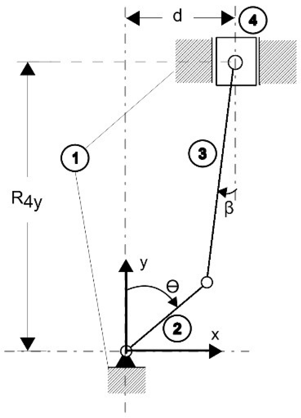
2.2. Kinematic Analysis of the Mechanism

A kinematic analysis of the system (piston, connecting rod, and crankshaft pin) is required. The system is considered as a slider-crank mechanism [25]. A schematic of the system is shown in Figure 2, in which Element 1 is ground (or the non-moving part of the engine), Element 2 is the crankshaft, and Elements 3 and 4 are the connecting rod and the engine piston, respectively.
Using complex algebra, the velocity and acceleration of the piston in the decentralized slider-crank mechanism can be calculated by solving the Equations [25]:
[ L 3 · s e n ( β ) 1 L 3 · c o s ( β ) 0 ] [ ω 3 / 4 v 4 ] = [ L 2 · ω 2 · s e n ( θ ) L 2 · ω 2 · c o s ( θ ) ]
[ L 3 · s e n ( β ) 1 L 3 · c o s ( β ) 0 ] [ α 3 / 4 a 4 ] = [ L 2 · ω 2 2 · [ cos ( θ ) ] L 3 · ω 3 / 4 2 · [ cos ( β ) ] L 2 · ω 2 2 · [ sen ( θ ) ] + L 3 · ω 3 / 4 2 · [ sen ( β ) ] ]
where L 2 and L 3 are the lengths of the crankshaft arm and connecting rod respectively, while v 4 = R ˙ 4 y is the piston velocity with respect to the reference coordinate system. Similarly, ω 2 = θ ˙ and ω 3 / 4 = β ˙ , or the derivative of the angle between the connecting rod and the piston displacement axis. This angle can be calculated by the equation
β = sen 1 [ d L 2 · [ sen ( θ ) ] L 3 ]
By solving this system given in Equations (5) and (6), the speed and angular acceleration of the connecting rod are obtained, together with the velocity and acceleration of the piston, for each angular position of the mechanism.

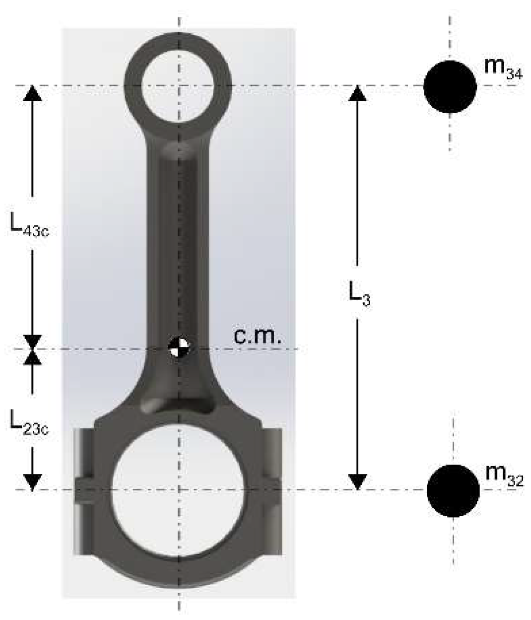
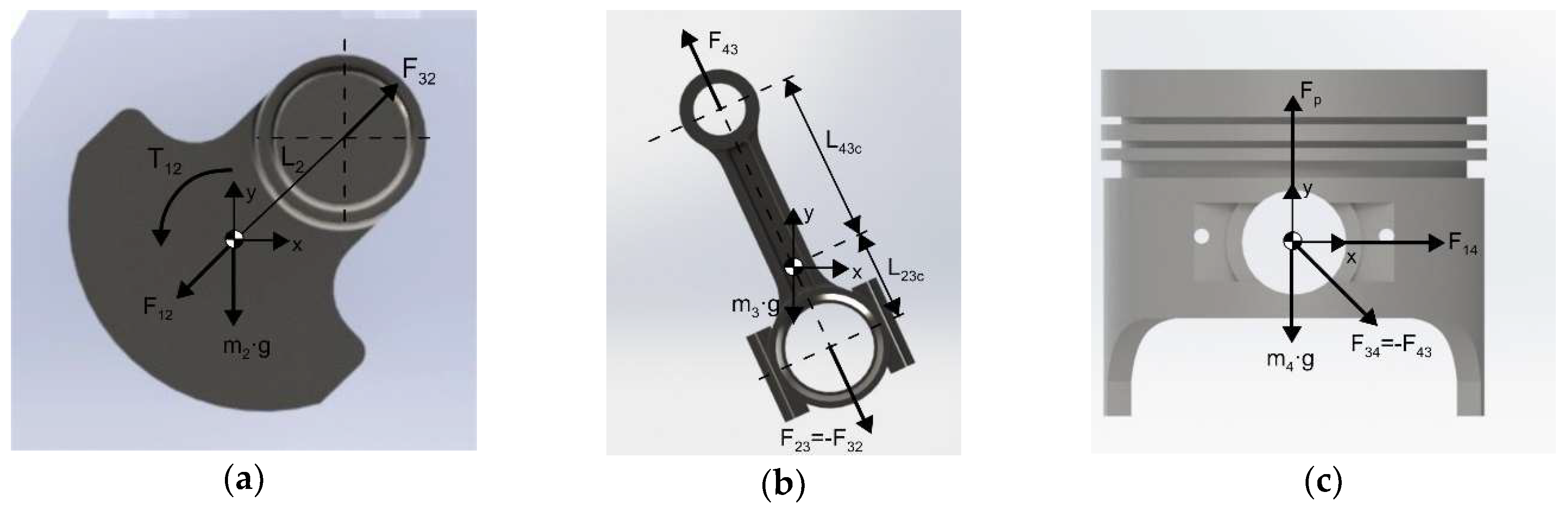
2.3. Kinetic Analysis of the Mechanism

To determine the forces applied on joints between components (which are necessary for the mathematical clearance model), the system is described as a crank-sliding mechanism, in which each part of the system will be analyzed separately (as shown in Figure 3). In the end, the expressions obtained will be unified in systems of linear equations in order to find the required unknowns.
The crankshaft analysis leads to the following Equations
F 32 x + F 12 x = 0
F 32 y + F 12 y + m 2 · g = 0
T 12 + ( L 2 x · F 32 y L 2 y · F 32 x ) = 0
For the connecting rod, the analysis generates the following Equations
F 32 x + F 43 x = m 3 · a G 3 x
F 32 y + F 43 y + m 3 · g = m 3 · a G 3 y
( L 23 c , x · F 32 y L 23 c , y · F 32 x ) + ( L 43 c , x · F 43 y L 43 c , y · F 43 x ) = I G 3 · α G 3
While for the piston, taking into account the pressure generated by the gas p g a s , the analysis leads to the following Equations
F x 43 + F 14 x = 0
F 43 y + p g a s · A 4 + m 4 · g = m 4 · a 4
By coupling (8) to (15), the following matrix is obtained
[ 1 0 1 0 0 0 0 0 0 1 0 1 0 0 0 0 0 0 L 2 y L 2 x 0 0 0 1 0 0 1 0 1 0 0 0 0 0 0 1 0 1 0 0 0 0 L 23 c , y L 23 c , x L 43 c , y L 43 c , x 0 0 0 0 0 0 1 0 1 0 0 0 0 0 0 1 0 0 ] [ F 12 x F 12 y F 32 x F 32 y F 43 x F 43 y F 14 x T 12 ] =     | 0 m 2 · g 0 m 3 · a G 3 x m 3 · a G 3 y m 3 · g I G 3 · α G 3 0 m 4 · a 4 p g a s · A 4 m 4 · g |

2.4. Instantaneous Geometric Volume Calculation

The volume in the cylinder, when the effects of the instantaneous variations are not considered, is composed of two terms [16]:
  • The minimum combustion chamber volume, which is the free space remaining when the piston reaches the top dead center (TDC). This is not dependent on the angular position of the crankshaft:
    V c c = π · D 4 2 4 · 2 · L 2 r c 1
    where r c is the engine compression ratio.
  • The volume displaced by the stroke of the piston in its path, which depends on the angular position of the crankshaft:
    V d ( θ ) =   π · D 4 2 4 · [ R 4 y , m a x R 4 y ( θ ) ]
For centralized geometries (d = 0), R 4 y , m a x = L 2 + L 3 , and (18) becomes:
V d ( θ ) =   π · D 4 2 4 · [ L 2 + L 3 R 4 y ( θ ) ]
Besides these terms, the pressure of the gases and the inertial forces of the mechanism, generate a variation in the instantaneous volume of the combustion chamber. This variation was studied by previously [25], and it is calculated by (20),
Δ V p , i = π · D 4 2 4 · K d e f E s t e e l · ( p g a s · A 4 + m i · a 4 ) A C R · L 3
with A C R being the area of the slender Section of the connecting rod.

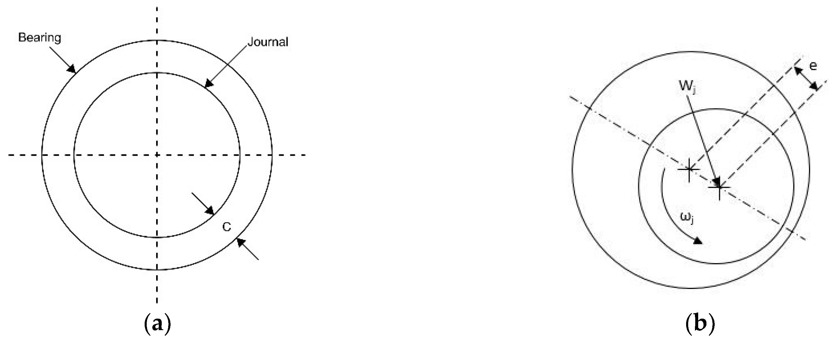
2.5. Mathematical Model of Clearance

In its most basic form, a sliding bearing consists of two elements: a cylindrical shaft, a shaft or a journal to which a load and a rotational speed are applied, and a cylindrical sleeve or bearing, which supports the journal as well as the load exerted. When there is no relative motion between these elements or an applied load (Figure 4a), these two elements are concentric to each other, separated by a radial clearance C [26]. If a load is applied, or there is a relative movement, these elements are no longer completely concentric. Because of the lubricant film behavior, there is an eccentricity e along the imaginary line joining the centers of the journal and bearing (Figure 4b). This is commonly expressed through the eccentricity ratio ε, which corresponds to the dimensionless relationship between eccentricity and radial clearance. Being defined in this way, the eccentricity ratio can only take values between zero and one.
ε = e C
The origin of volume variation due to clearance lies in the behavior of the lubricating film. Therefore, the mathematical modeling of the previous phenomenon is developed from the Reynolds lubrication equation. For pure tangential sliding motion, pressure changes within the lubricant film due to the physical wedge mechanism. In this case, the flow perpendicular to the direction of motion (side-leakage effect) has to be included, and the Reynolds equation takes the form [27]:
x ( h 3 μ p x ) + z ( h 3 μ p z ) = 3 · D j · ω j h x
where h corresponds to the film height, p to the pressure exerted on the lubricant, Dj to the diameter of the bearing, ωj is the angular velocity of the hub, and μ is the dynamic viscosity of the lubricant. Due to the complexity of the solution of (22), Vignolo et al. [28] validated an approximate analytical solution developed by Dubois [29], that takes care of side leakage and assumes that the pressure-induced flow in the circumferential direction is small relative to the Couette flow term. This assumption further implies that the Poiseuille flow is less significant in the circumferential direction. This short bearing theory is valid as long as the diameter-to-width ratio is greater than 2, which is fulfilled in this case. Because of this assumption, the Reynolds equation reduces to:
x ( h 3 μ p x ) = 3 · D j · ω j h x
To calculate the film height h, a first approximation is obtained from a geometrical analysis of the bearing with an eccentricity e, as shown in Figure 5. As a result, the film height expression has the following structure [26]:
h = e · cos σ + R a · cos δ R b
Equation (24) fulfills the objective of providing an expression for the film height. Nevertheless, it is ambiguous and difficult to implement. Because of this, trigonometric relations from (25) are used to obtain (26),
e sin δ = R a sin σ
h = C ( ε · cos σ + 1 )
In the literature, it is common to find the mathematical modeling of the parameters necessary for the design of a radial short bearing, such as the load capacity that the film can withstand without breaking, and the position of the locus with the smallest film size (which corresponds to the position of the center line). However, these parameters are described under the condition of zero motion for the bearing. That is, the journal is subjected to a defined rotational speed, while the former is held fixed [26]. In the event that the above is not met, it is possible to replace the original system—bearing with rotational speed ωj and static journal—by an equivalent system in which the bearing is fixed, and the journal has an opposite rotational speed to the original, in order to maintain relative rotation between the two elements. For this, an additional coordinate system is applied as shown in Figure 6, which has an orientation β concerning the original system. Since this system changes its orientation at each instant, it becomes necessary to transform the resulting loads considering the fixed coordinate system to apply the following mathematical analysis. From trigonometric relations, loads of the new system are expressed by [25,29]:
P j = 3 · μ · ω j · D j 2 · C 2 ( 1 + ε · cos σ ) 3 · ( ε · sin σ R j ) ( Z 2 L j 2 4 )
U j = ω j · D j 2
P j = 3 · μ · U j C 2 ( 1 + ε · cos σ ) 3 · ( ε · sin σ R j ) ( Z 2 L j 2 4 )
Using the definition of lubricant film pressure and circumferential velocity Uj, the axis components of the load Wj are obtained by the following:
W j x = W j · cos σ = 0 π L 2 L / 2 P j · R j · cos σ d Z d θ
W j · cos σ = μ · ω j · D j · L j 3 2 · C 2 2 · ε 2 ( 1 ε 2 ) 2
W j y = W j · sin σ = 0 π L 2 L / 2 P j · R · sin σ d Z d θ
W j · sin σ = μ · ω j · D j · L j 3 4 · C 2 ε ( 1 ε 2 ) 3 2
From these components, the magnitude of the resulting load and its orientation is known by:
W j = W j x 2 + W j y 2
W j = ε 4 · μ 2 · U j 2 · L j 6 ( 1 ε 2 ) 4 · C 4 + π 2 · ε 2 · μ 2 · ω j 2 · D j 2 · L j 6 16 ( 1 ε 2 ) 3 · C 4
W j = ω j · D j · μ · L j 3 · ε · π 8 · C 2 · ( 1 ε 2 ) 2 ( 16 π 2 1 ) ε 2 + 1
ζ j = arctan ( W j y W j x )
Once the above is obtained, the relevant parameters for the free height variation are determined, which are the eccentricity value e (or the eccentricity relation ε), and the location angle ζ j . These variables are represented graphically in Figure 6b.
Using the previous complex mathematical analysis, it is shown that the load capacity for a short-width journal bearing, is related to the eccentricity ratio, by the expression [25,26]:
W j = μ · ω j · D j · L j 3 8 · C 2 · π · ε · [ 0.62 ε 2 + 1 ] 0.5 ( 1 ε 2 ) 2
Assuming a static equilibrium between the journal load and the reaction exerted by the oil film, the value of ε and the angle of inclination of the center line is estimated, which is measured from the line of application of the load, in the direction of rotation of the journal. This is calculated by:
ϕ c = arctan ( π 2 · 1 ε 2 ε )
With these two values, it is possible to determine the angle that forms the center line with the x’ axis, through two relations:
γ = ζ j + ϕ c ,   if   ω j > 0
γ = ζ j ϕ c ,   if   ω j < 0
From this, the free height clearance variation is expressed by:
Δ y h = e · sin ( γ )
However, this is the variation of height related to the coordinate system located along the connecting rod. To bring this to the original coordinate system, the following expression is used:
Δ y h = Δ y h · cos ( β ) = e · sin ( γ ) · cos ( β )
Due to the number of joints present in the mechanism, the individual contribution of each of them over the volume variation should be considered. For this reason, the variation of volume by clearances is expressed by:
Δ V h = π · D 4 2 4 · m = 1 n [ e m · sin ( γ m ) · cos ( β m ) ]

2.6. Determination of Instantaneous Volume

From Equations (17), (18), (19) and (20), a unique expression can be formulated to describe the cylinder volume, for each angular position of the crankshaft. In this expression, the volume variation due to deformations by pressure and inertia are taken into account, and it is expressed mathematically by:
V p , i ( θ ) = π · D 4 2 4 · { 2 L 2 ( r c 1 ) + L 2 + L 3 R 4 y ( θ ) + K d e f E s t e e l · A C R · L 3 · [ p g a s A 4 + m i · a 4 ] }
where the constant of mechanical deformations Kdef, corresponds to a unique value for each engine, which must be adjusted from experimental data. Including the effect of clearances (Equation (44)), the above expression becomes:
V ( θ ) = π · D 4 2 4 · { 2 L 2 ( r c 1 ) + L 2 + L 3 R 4 y ( θ ) + K d e f E s t e e l · A C R · L 3 · [ p g a s A 4 + m i · a 4 ] + i = 1 2 e i · sin ( γ i ) · cos ( β i ) }
This expression calculates the instantaneous volume, considering all the effects studied (pressure, inertia, and clearance).

3. Result Methodology

The methodology used covers a series of stages. Initially, a treatment of the pressure data from the combustion chamber measured in the SOKAN SK-MDF300 diesel direct injection engine whose geometric characteristics can be consulted in Table 1, was carried out through the fast Fourier transform (FFT) with a cut-off frequency of 44 kHz. This is an accurate value for the type of analysis developed in this work. This pressure data was measured for three-rotational speed regimes: 1500, 2500, and 3500 rpm, which are common operation values for the studied engine.
The filtered pressure data was used for the simulation of the engine in ANSYS®, from which the piston free height variation due to pressure and inertia deformation was obtained. To do so, the mesh for the connecting rod was generated by the tetra patch conforming method, with a degree of refinement (relevance) of 100, generating tetrahedral elements with an average asymmetry coefficient (skewness) of 0.21. Further, the frictional contact for the simulation was obtained from [30,31], which includes shear stress and viscous effects. The mechanical data of the simulated elements are summarized in Table 2.
To verify that the results obtained in the simulation were consistent with experimental data, validation was performed on the universal testing machine, whose characteristics are illustrated in Table 3.
The obtained results were compared with the developed model, without taking into account the volume variation due to clearances, as shown in Equation (45), and allowed the validation of the proposed model and the calculation of the mechanical deformation coefficient, Kdef. Likewise, the volume variation due to clearances was obtained, and its relevance in the instantaneous volume change was emphasized. A sensitivity analysis was carried out using a combustion diagnosis model [15,16]. Using the in-cylinder pressure signal, the rate of heat release (ROHR) and the temperature in the combustion chamber are obtained. This will emphasize the importance of the correct prediction of the volume in the combustion chamber and will help to study the influence of the volume variation, which is the main objective of the present research.
The results obtained in the universal test machine were compared with the simulation results in Table 4, validating that the simulations adequately describe the phenomena under study.
The validation was carried out at the top dead center, because at this point the load acts at compression, which is a loading mode in which the piston rod assembly can be tested in the universal machine, due to limitations in the fixing of the elements to the machine. This validates the results obtained from the simulation. The variations can be attributed to changes in the simulated geometry used in ANSYS®, and that affects the deformation values obtained. Likewise, there is uncertainty between the materials simulated and the materials used in the real power train. Despite that, the maximum error in the prediction does not exceed 2%.
In Section 2.6, it was mentioned that pressure in the combustion chamber is the starting point for the calculation of volume variations due to clearances, as the load profile for journal bearings (a mandatory input for the estimation of lubricant film thickness) varies according to the measured pressure in the engine. Given the existence of previous works that evaluate the behavior of lubricant films in conditions similar to that described, the validation was performed using the experimental load profiles measured by Moreau [32] (as shown in Figure 7). These values were used as input in the model and the minimum film thickness was obtained for each angular position of the crankshaft. This procedure is summarized graphically in Figure 8.
In Figure 9, the values calculated by the proposed model were compared with the experimental results obtained by Moreau et al. [32], where deviations are less than 5% when compared to data sets. This graph allowed to verify the capacity of the model to predict the behavior of minimum film thickness, and, therefore, the journal eccentricity originated by the operating conditions. Since Equation (42) establishes the relation between the eccentricity and the instantaneous volume variation in the combustion chamber, it can be inferred that the proposed model can produce a robust prediction of the film effects on the volume changes due to clearances.

4. Results and Discussion

As defined above, Equation (20) is expressed as a function of an adjustment coefficient Kdef that takes into account the uncertainties of the proposed model and is adjusted so that the rate of heat release is zero in the motored engine, because there is no combustion. Therefore, if the coefficient is not adjusted properly, it causes an error in the variation of instantaneous volume. To estimate the value of the deformation coefficients, the volume variation obtained in ANSYS® was compared with the calculated value for each angular position of the crankshaft. These results were obtained for each regimen, and after statistical analysis, the mean and standard deviation of the coefficient for each engine speed was obtained. Table 5 shows the values for these statistical parameters.
This shows that the values obtained by the proposed model meet the homoscedasticity condition, that is, its mean and standard deviation remain almost constant throughout the studied regimes. Additionally, it was noticed that these values are remarkably close to the ideal case. That is, Kdef is equal to one. From the results of Table 5, the global value of 1.15 was assigned as the coefficient of deformations of the studied engine, which produces adequate results when the adjusted model is compared with the ANSYS® results, as shown in Figure 10, Figure 11 and Figure 12 for 1500, 2500, and 3500 rpm.
To demonstrate that the clearance plays a significant role in the instantaneous volume throughout the working cycle, Equation (44) was used, with the help of Octave®, to obtain the volume variation due to the lubricating film. The clearance model described before was applied to two points of interest: the piston pin-connecting rod and the crankshaft junction, for each regimen, studied (1500, 2500, and 3500 rpm), using the properties of SAE 15W-40 lubricant oil. The geometric properties of these joints are summarized in Table 6, and the results obtained in Octave® are shown in Figure 13.
By direct comparison of volume variation due to pressure, inertia and clearances (shown in Figure 14 at 1500 rpm), it is noticed that the volume variation due to the latter represents approximately 66% of the range comprised by deformations due to pressure and inertia. Furthermore, it was found that clearances model presents an almost constant variation through the thermodynamic cycle, unlike the variations due to pressure and inertia, which are manifested largely near the TDC (approximately about 120° of rotation of the crankshaft). As a result of the above, it is assumed that the behavior of the lubricating film is a factor required to calculate the overall variation of the free height of the piston, and hence the instantaneous volume variation in the combustion chamber.
Taking into account previous research [15,33,34,35] and the fact that there is a relation between the volume of the combustion chamber and the inside temperature reached, it is evident the influence of the volume variation due to pressure and clearances on the thermodynamic modeling [36]. Additionally, diagnostics thermodynamic modeling shows variations in the rate of heat release due to changes in the compression ratio, which in turn is caused by the change of volume in the combustion chamber. Therefore, this investigation shows the influence of volume variation on thermodynamic modeling, using the DIAGNO-DIESEL® software for 1500, 2500, and 3500 rpm. These angular velocities were chosen to take into account the entire range of operation speed for the engine under study.
After engine characterization, the average temperature in the chamber and rate of heat release (ROHR) are analyzed, considering the crankshaft angle. Figure 15 shows the influence of the volume variation of the combustion chamber on the thermodynamic modeling for the studied regimes, where variations up to 4% in the mean temperature in the chamber are observed. In the same way, the variation in the ROHR for different engine speeds was calculated (and shown in Figure 15) and it is emphasized that the best result is obtained when the model including deformation and clearance proposed in the actual research is used.

5. Conclusions

The application of the filtering methodology to the supplied pressure data allowed obtaining reliable information to be used in the simulation because it permits the elimination of low-frequency noises (by averaging a certain amount of thermodynamic cycles) and high frequency (by the application of the fast Fourier transform) presented in the original signal. Moreover, its programming simplicity, in tools like Octave®, makes it a convenient way to isolate the useful information contained in the acquired pressure signal.
On the other hand, the implementation of a simulation package, such as ANSYS®, using the experimental pressure data in the chamber allowed the direct estimation of the coefficient of mechanical deformations of Equation (45), which was characterized by maintaining a low variability between each studied regimen. This allowed obtaining a unique value Kdef of 1.15 for the studied engine, which produces a reasonable adjustment of the model to the experimental data. From this, the volume variation model due to pressure and inertia is validated as a fast and precise way of characterizing the engine, which leads to the reduction of uncertainties in the process, compared with the iterative process currently used. This leads to an improvement in the calculation of the heat release rate, due to the reduction of uncertainties in one of the sub-models involved in the global balance.
Regarding the volume variation by clearances, the results obtained in Octave® indicate that the lubricant film has a significant influence on the global variation of instantaneous volume, with variations that represent 66% of the deformation produced by the pressure and inertial load, which causes a significant change in the prediction of the thermodynamic behavior of the engine. For these reasons, it is necessary to include them in thermodynamic modeling and its experimental validation, because of the notable influence on the chamber temperature as seen in Figure 15.
Figure 15 shows an improvement in the prediction of ROHR using the model developed in the present investigation, taking into account that the rate of heat release must be close to zero in the condition of motored test since there is no combustion. The study was limited to this condition to avoid external uncertainties due to the combustion process. When the engine speed was increased, it was verified that the ROHR also increased (Figure 15). However, it is observed that the joint influence of the deformation by pressure/inertia and tolerances is significant since it can generate deviations of up to 300% in the ROHR.
The results show that there is a higher average temperature and ROHR when the volume variation in the combustion chamber as shown by Equation (46) is not taken into account. This is because in the previous studies of thermodynamic modeling of diesel engine did not consider volume changes due to clearances. In many cases, the deformation energy due to pressure and inertia forces is not considered, which in the present study was taken into account and caused greater predictability.

Author Contributions

All the authors of the present research contributed equally to conducting and writing this paper.

Funding

This research received no external funding.

Acknowledgments

Acknowledgments to Universidad del Atlántico, to Sphere Energy Company and Colombian Institute for Scientific and Technological Development (COLCIENCIAS) through the “Convocatoria Nacional para Estudios de Doctorado en Colombia año 2012” for the support provided.

Conflicts of Interest

The authors declare no conflict of interest.

Abbreviations

The following abbreviations are used in this manuscript:
ICEInternal combustion engine
TDCTop dead center
BDCBottom dead center
CFDComputational fluid dynamics
ROHRRate of heat release
FFTFast fourier transform
CADComputer-aided design
Nomenclature
m Mass
L Length
E Elastic modulus
E s t e e l Elastic modulus of steel
K d e f Deformation constant
v Velocity
a Acceleration
d Horizontal distance between piston axis
F Force
T Torque
I Inertia moment of mass
g Acceleration of gravity
p g a s Pressure of gases
A Area
A C R Connecting rod’s critical area
V Volume
r c Compression ratio
R 4 y Vertical position of the piston
D Diameter
e Eccentricity between journal and bearing, measured along their centerline
C Radial clearance
h Lubricant film thickness
R Length of a radius
P Load applied, based on the journal coordinate system
U Circumferential velocity
W Specific load in the journal
Greek Letters
θ Angle of rotation
β Angle between the connecting rod and the piston displacement axis
ω Angular speed
α Angular acceleration
ε Eccentricity ratio
Δ Variation or difference
μ Dynamic viscosity
σ Angle between the eccentricity and the horizontal axis
δ Angle between the journal and bearing radius
ϕ Angle of the line between centers
ζ Angle of the applied load
Subscripts
1 Engine block
2 Crankshaft
3 Connecting rod
4 Piston
34 , 43 Between piston and connecting rod
32 , 23 Between connecting rod and crankshaft
p Pressure
i Inertial loads
3 / 4 Relative movement between rod and piston
x , y Cartesian components
c ,   G Center of mass
c c Combustion chamber
d Displacement
h Clearances
j Journal bearing

References

  1. Harigaya, Y.; Suzuki, M.; Toda, F.; Takiguchi, M. Analysis of oil film thickness and heat transfer on a piston ring of a Diesel engine: effect of lubricant viscosity. J. Eng. Gas Turbines Power 2004, 128, 685–693. [Google Scholar] [CrossRef]
  2. Heywood, J. Internal Combustion Engine Fundamentals; McGraw-Hill Education: New York, NY, USA, 1988; ISBN 007028637X. [Google Scholar]
  3. Valery, C.; Abbe, N.; Nzengwa, R.; Danwe, R.; Merlin, Z.; Obonou, M. A study on the 0D phenomenological model for diesel engine simulation: Application to combustion of Neem methyl esther biodiesel. Energy Convers. Manag. 2015, 89, 568–576. [Google Scholar] [CrossRef]
  4. Duarte, J.; Garcia, J.; Jiménez, J.; Sanjuan, M.E.; Bula, A.; González, J. Auto-ignition control in spark-ignition engines using internal model control structure. J. Energy Resour. Technol. 2016, 139, 022201. [Google Scholar] [CrossRef]
  5. Baratta, M.; Catania, A.E.; d’Ambrosio, S.; Spessa, E. Prediction of Combustion Parameters, Performance, and Emissions in Compressed Natural Gas and Gasoline SI Engines. J. Eng. Gas Turbines Power 2008, 130, 062805. [Google Scholar] [CrossRef]
  6. Jung, D.; Assanis, D.N. Multi-Zone DI Diesel Spray Combustion Model for Cycle Simulation Studies of Engine Performance and Emissions. SAE Trans. 2001, 1510–1532. [Google Scholar] [CrossRef]
  7. Hiroyasu, H.; Kadota, T.; Arai, M. Development and use of a spray combustion modeling to predict Diesel engine efficiency and pollutant emissions. Part 1: Combustion modeling. Bull. JSME 1983, 26, 569–575. [Google Scholar] [CrossRef]
  8. Amador, G.; Forero, J.D.; Rincon, A.; Fontalvo, A.; Bula, A.; Padilla, R.V.; Orozco, W. Characteristics of auto-ignition in internal combustion engines operated with gaseous fuels of variable methane number. J. Energy Resour. Technol. 2017, 139, 42205. [Google Scholar] [CrossRef]
  9. Asano, K.; Ito, Y.; Tsunoda, T.; Suzuki, I. Advanced gas engine diagnosis system for cogeneration. In Proceedings of the International Gas Research Conference, Cannes, France, 6 November 1995; pp. 337–346. [Google Scholar]
  10. Baratta, M.; Catania, A.E.; Ferrari, A.; Finesso, R.; Spessa, E. Premixed-Diffusive Multizone Model for Combustion Diagnostics in Conventional and PCCI Diesel Engines. J. Eng. Gas Turbines Power 2011, 133, 102801–102813. [Google Scholar] [CrossRef]
  11. Barba, C.; Burkhardt, C.; Boulouchos, K.; Bargende, M. A phenomenological combustion model for heat release rate prediction in high-speed DI Diesel engines with common rail injection. SAE Tech. Pap. 2000. [Google Scholar] [CrossRef]
  12. Irimescu, A.; Di Iorio, S.; Merola, S.S.; Sementa, P.; Vaglieco, B.M. Evaluation of compression ratio and blow-by rates for spark ignition engines based on in-cylinder pressure trace analysis. Energy Convers. Manag. 2018, 162, 98–108. [Google Scholar] [CrossRef]
  13. Brunt, M.F.J.; Rai, H.; Emtage, A.L. The Calculation of Heat Release Energy from Engine Cylinder Pressure Data. SAE Trans. 1998, 107, 1596–1609. [Google Scholar]
  14. Fathi, M.; Saray, R.K.; Checkel, M.D. Detailed approach for apparent heat release analysis in HCCI engines. Fuel 2010, 89, 2323–2330. [Google Scholar] [CrossRef]
  15. Aronsson, U.; Solaka, H.; Lequien, G.; Andersson, O.; Johansson, B. Analysis of Errors in Heat Release Calculations Due to Distortion of the In-Cylinder Volume Trace from Mechanical Deformation in Optical Diesel Engines. SAE Int. J. Engines 2012, 5, 1561–1570. [Google Scholar] [CrossRef]
  16. West, I.A.; Moreno, C.J.; Stenlåås, O.; Haslestad, F.; Jönsson, O. Internal Combustion Engine Cylinder Volume Trace Deviation. SAE Int. J. Engines 2018, 11, 195–214. [Google Scholar] [CrossRef]
  17. Sun, J.; Cai, X.; Liu, L. Research on the effect of whole cylinder block on EHL performance of main bearings considering crankshaft deformation for internal combustion engine. J. Tribol. 2010, 132, 44502–44506. [Google Scholar] [CrossRef]
  18. Sun, J.; Gui, C. Effect of lubrication status of bearing on crankshaft strength. J. Tribol. 2007, 129, 887–894. [Google Scholar] [CrossRef]
  19. Weinzapfel, N.; Sadeghi, F.; Bakolas, V.; Liebel, A. A 3D finite element study of fatigue life dispersion in rolling line contacts. J. Tribol. 2011, 133, 42202–42210. [Google Scholar] [CrossRef]
  20. Cai, S.; Bhushan, B. Three-dimensional dry/wet contact analysis of multilayered elastic/plastic solids with rough surfaces. J. Tribol. 2005, 128, 18–31. [Google Scholar] [CrossRef]
  21. Mo, J.; Gu, C.; Pan, X.; Zheng, S.; Ying, G. A thermohydrodynamic analysis of the self-lubricating bearings applied in gear pumps using Computational Fluid Dynamics method. J. Tribol. 2017, 140, 11102–11109. [Google Scholar] [CrossRef]
  22. Panayi, A.; Schock, H.; Chui, B.-K.; Ejakov, M. Parameterization and FEA approach for the assessment of piston characteristics. SAE Tech. Pap. 2006. [Google Scholar] [CrossRef]
  23. Cheng, C.; Akinola, A. Piston friction reduction by reducting piston compression height for large bore engine applications. SAE Int. J. Engines 2017, 10, 1940–1947. [Google Scholar] [CrossRef]
  24. Duarte Forero, J.; Guillín Estrada, W.; Sánchez Guerrero, J. Desarrollo de una metodología para la predicción del volumen real en la cámara de combustión de motores diésel utilizando elementos finitos [Developmet of a methodology to predict the real volume of the combustion chamber of an internal combustion diesel engine using finite elements]. INGE CUC 2018, 14, 122–132. [Google Scholar] [CrossRef]
  25. Perera, M.S.M.; Theodossiades, S.; Rahnejat, H. Elasto-multi-body dynamics of internal combustion engines with tribological conjunctions. Proc. Inst. Mech. Eng. Part K J. Multi-Body Dyn. 2010, 224, 261–277. [Google Scholar] [CrossRef] [Green Version]
  26. Naffin, R.K.; Chang, L. An analytical model for the basic design calculations of journal bearings. J. Tribol. 2010, 132, 024503. [Google Scholar] [CrossRef]
  27. Vignolo, G.G.; Barilá, D.O.; Quinzani, L.M. Approximate analytical solution to Reynolds equation for finite length journal bearings. Tribol. Int. 2011, 44, 1089–1099. [Google Scholar] [CrossRef]
  28. Dubois, G.B.; Ocvirk, F.W. Analytical Derivation and Experimental Evaluation of Short-Bearing Approximation for Full Journal Bearing; NACA Technical Report 1157; National Advisory Comitee for Aeronautics: Washington, DC, USA, 1953. [Google Scholar]
  29. Bushan, B. Modern Tribology Handbook; CRC Press LLC: Boca Raton, FL, USA, 2001; ISBN 0-8493-8403-6. [Google Scholar]
  30. Abdullah, O.I.; Akhtar, M.J.; Schlattmann, J. Investigation of thermo-elastic behavior of multidisk clutches. J. Tribol. 2014, 137, 11703–11709. [Google Scholar] [CrossRef]
  31. Jung, C.; Epureanu, B.I.; Baik, S.; Huffman, M.B. Nonlinear reduced order models for the structural dynamics of combustor systems with prestress and friction. J. Comput. Nonlinear Dyn. 2014, 10, 11008–11009. [Google Scholar] [CrossRef]
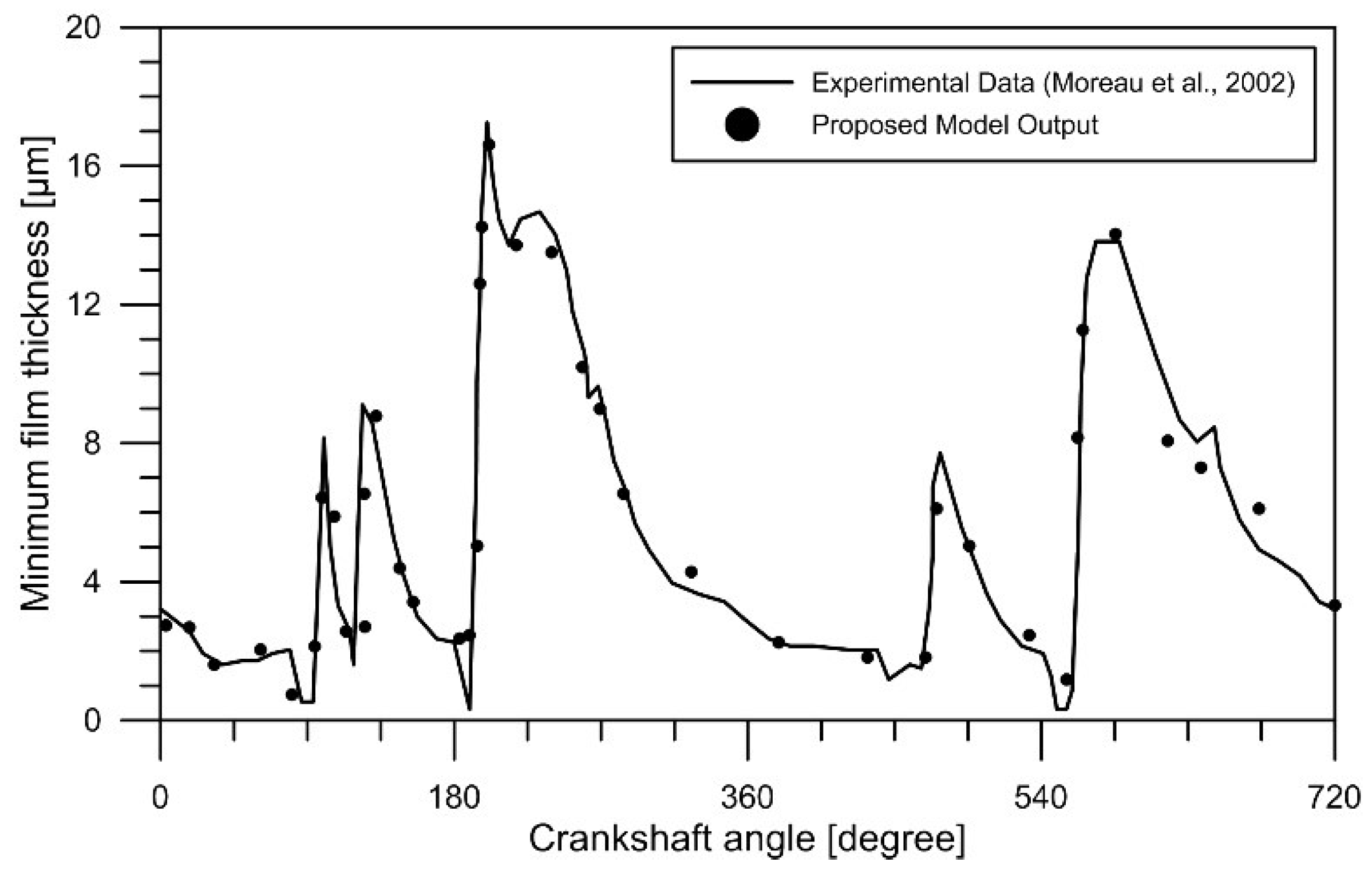
  32. Moreau, H.; Maspeyrot, P.; Chomat-Delalex, A.M.; Bonneau, D.; Frene, J. Dynamic behaviour of elastic engine main bearings: Theory and measurements. Proc. Inst. Mech. Eng. Part J J. Eng. Tribol. 2002, 216, 179–194. [Google Scholar] [CrossRef]
  33. Arrègle, J.; López, J.J.; García, J.M.; Fenollosa, C. Development of a zero-dimensional Diesel combustion model. Part 1: Analysis of the quasi-steady diffusion combustion phase. Appl. Therm. Eng. 2003, 23, 1301–1317. [Google Scholar] [CrossRef]
  34. Zamboni, G. A Study on Combustion Parameters in an Automotive Turbocharged Diesel Engine. Energies 2018, 11, 2531. [Google Scholar] [CrossRef]
  35. Liu, Q.; Liu, Z.; Han, Y.; Tian, J.; Wang, J.; Fang, J. Experimental Investigation of the Loading Strategy of an Automotive Diesel Engine under Transient Operation Conditions. Energies 2018, 11, 1293. [Google Scholar] [CrossRef]
  36. Duarte, J.; Amador, G.; García, J.; Fontalvo, A.; Vásquez, R.; Sanjuan, M.; Gonzalez, A. Auto-ignition control in turbocharged internal combustion engines operating with gaseous fuels. Energy 2014, 71, 137–147. [Google Scholar] [CrossRef]
Figure 1. Statically equivalent mass system for connecting rod.
Energies 12 01437 g001
Figure 2. Scheme kinematic model for decentered sliding rod-crank-mechanism.
Energies 12 01437 g002
Figure 3. Free-body diagrams for (a) the crankshaft, (b) connecting rod and (c) piston.
Energies 12 01437 g003
Figure 4. Schematic of a sliding bearing: (a) with no load applied, and (b) with a load applied to the journal.
Energies 12 01437 g004
Figure 5. Bearing geometrical analysis.
Energies 12 01437 g005
Figure 6. Graphic representation of the journal bearing parameters: (a) coordinate system transformation angles and (b) resultant load and centerline orientation.
Energies 12 01437 g006
Figure 7. Experimental load profile used for the validation, measured by Moreau et al. at 5500 rpm and full load [32].
Energies 12 01437 g007
Figure 8. Schematic of the procedure used for the validation of the clearance model.
Energies 12 01437 g008
Figure 9. Comparison of values obtained for minimum film thickness.
Energies 12 01437 g009
Figure 10. Results of ANSYS® and the adjusted model, at 1500 rpm.
Energies 12 01437 g010
Figure 11. Results of ANSYS® and the adjusted model, at 2500 rpm.
Energies 12 01437 g011
Figure 12. Results of ANSYS® and the adjusted model, at 3500 rpm.
Energies 12 01437 g012
Figure 13. Volume variation due to clearance for regimens studied.
Energies 12 01437 g013
Figure 14. Variation of volume by clearance and adjusted model, for 1500 rpm.
Energies 12 01437 g014
Figure 15. Results obtained for (a,c,e) in-cylinder temperature and (b,d,f) rate of heat release for 1500 rpm, 2500 rpm, and 3500 rpm, respectively.
Energies 12 01437 g015
Table 1. Geometric characteristics of the engine SOKAN SK-MDF300.
ElementValue
Connecting rod length [mm]105.85
Piston mass [kg]0.305
Piston pin mass [kg]0.1262
Segments mass [kg]0.0361
Crankshaft arm radius [mm]36.37
Connecting rod mass [kg]0.3533
Piston diameter [mm]78.00
Steel elasticity modulus [GPa]210.00
Piston pin diameter [mm]21.00
Compression ratio20:1
Area   of   critical   Section   of   connecting   rod   [ mm 2 ] 115.96
Piston   area   [ mm 2 ] 4778.36
Piston   pin   area   [ mm 2 ] 346.36
Table 2. Materials used in the mechanism simulation.
ElementMaterialDensity [kg/ m3]Mass [kg]
Connecting rodAlloy Steel63100.873
CrankshaftStainless Steel870015.744
Piston pinPlain Carbon Steel78000.218
PistonAluminum Alloy27000.523
Table 3. Characteristics of universal testing machine.
ParameterValue
ManufacturerJinan Liangong Testing Technology Co., Ltd.
Maximum load test [kN]600
Precision [%]0.1
Repeatability [%]+/− 0.025
Maximum acceleration [m/s2]10−3
Table 4. Comparative experimental results—ANSYS simulation.
TestLoad Universal Test Machine [N]Deformation Universal Test Machine [mm]Load ANSYS Simulation
[N]
Deformation ANSYS Simulation [mm]
TDC-Compression18965.430.0530118966.520.05323
TDC-Exhaust600.960.00236601.420.00251
Table 5. Values obtained from the coefficient of deformation Kdef.
Engine SpeedKdef Proposed Model
AverageStandard Deviation
1500 rpm1.1530.0511
2500 rpm1.1480.0689
3000 rpm1.1570.0697
Table 6. Geometric characteristics of the joints studied.
DimensionPiston Pin–Connecting RodConnecting Rod–Crankshaft
Length [mm]25.0019.10
Nominal Diameter [mm]21.0035.90
Radial clearance [mm]0.01750.027
Surface Roughness [mm]5.25 × 10−55.25 × 10−5

