Article

Estimation of Equivalent Circuit Parameters of Single-Phase Transformer by Using Chaotic Optimization Approach

1
Faculty of Electrical Engineering, University of Montenegro, 81000 Podgorica, Montenegro
2
Electric Power Utility of Montenegro, HPP “Perućica”, 81400 Nikšić, Montenegro
*
Author to whom correspondence should be addressed.
Submission received: 8 April 2019 / Revised: 28 April 2019 / Accepted: 29 April 2019 / Published: 5 May 2019
(This article belongs to the Section F: Electrical Engineering)

Abstract

:
This paper deals with parameter estimation of single-phase transformer equivalent circuit by using Chaotic Optimization Approach (COA). Unknown transformer equivalent circuit parameters need to be accurately estimated for the best possible matching between the measured and the estimated transformer output characteristics (for example, output power—load resistance characteristic). Unlike literature approaches which apply different estimation techniques and are based either on the nameplate data or the load data obtained from experiments, in this paper the use of COA is evaluated on both types of input data. For two single-phase transformers, different with respect to machine power and voltage levels, the COA-based parameter estimation is compared to various literature techniques as well as to classical method based on open-circuit and short-circuit tests. The results show that COA outperforms other approaches in terms of average error between the measured and the estimated values of the primary current, secondary current and secondary voltage at full load, or between the measured and the estimated output characteristics. The effectiveness of COA is additionally confirmed through its application on laboratory 2kVA, 220 V/110 V, 50 Hz single-phase transformer.

1. Introduction

Power transformers represent one of the main parts of transmission and distribution systems [1] and are ubiquitous in power electronics applications. Therefore, the analysis of power systems and of any power electronics circuit containing transformers, requires accurate transformer model [2,3].
Transformer modeling, i.e. the estimation of transformer equivalent circuit parameters, is an important subject in many studies (power systems, stability, modeling of power electronics converters etc.). It is necessary for transformer design, diagnostic purposes and service information [4,5]. Namely, equivalent circuit parameters characterize the behavior and performance of a transformer. Hence, estimation of transformer equivalent circuit parameters can provide significant information about the condition, performance and behavior of the machine, on one hand, and to its operation on grid, on the other.
Work on developing transformer model has been widely investigated. For that reason, a few different views on transformer parameters estimation can be found in the available literature [6,7,8,9,10,11,12,13,14]. Some of them include transformer’s nonlinear behavior [6,7,8], whereas others deal with traditional (Steinmetz) transformer equivalent circuit [9,10,11,12,13,14]. Since transformers and induction machines have similar equivalent circuit, some studies investigate parameter estimation of both induction machine and transformer [15,16]. This paper deals with parameter estimation of traditional (Steinmetz) equivalent circuit of single-phase transformer.
The equivalent circuit parameters of transformer can be determined based on its geometrical dimensions [17,18]. However, this approach is not useful for all transformers due to dimensional data unavailability, which is often case for old machines. On the other hand, these parameters can be determined from the standard test procedures, that are based on open-circuit and short-circuit tests, and hence cannot be used for transformers which are in operation [1]. In addition, deviation of environmental and operational conditions (such as temperature change, change of air conditions, short circuits, overloading etc.) can cause variation of the equivalent circuit parameters [16]. Single-phase transformer, considered in this paper, usually operates in a control system or in a measuring system. Therefore, the application of short-circuit and open-circuit tests require additional time for the tests realization and disconnection of the transformer from the power system, which is usually impossible to carry out.
Optimization techniques based on the evolutionary algorithms have become the most widely used methods in a large variety of optimization problems. The main advantage of the optimization techniques, based on the evolutionary algorithms is that the form of the cost (or goal) function can be defined arbitrary. This is reason why these techniques are also very popular for transformer parameters estimation [9,10,11,12,13,14,15,16]. They include Practical Swarm Optimization (PSO) [9,15,16], Genetic Algorithm (GA) [9,13], Imperialist Competitive Algorithm (ICA) [10], Gravitational Search Algorithm (GSA) [10], Bacterial Foraging Algorithm (BFA) [11,12] and Artificial Bee Colony Algorithm (ABCA) [14] and can be applied on transformer nameplate data or on the measured load data, without disconnection of the transformer from the power system. Let us briefly describe these techniques.
In [9], PSO and GA are used for the estimation of transformer parameters from the nameplate data and the estimated parameters are compared to the corresponding ones obtained from the standard tests—open-circuit and short-circuit tests. Furthermore, the estimated values of the primary current, secondary current and secondary voltage have been compared to the corresponding ones obtained from the full load test. The usage of ICA and GSA for transformer parameters estimation is proposed in [10] and compared to PSO and GA algorithms. In the optimization procedure in [10], unknown parameters are obtained by using an objective function which takes into account the values of primary current, secondary current and secondary voltage at full load. However, the differences between the estimated and the measured values of the primary current, secondary current and secondary voltage values at full load in the previous studies (especially in [9]) are significant.
The use of BFA for single-phase transformer parameter estimation based on the load data obtained from experiments is presented in [11]. The estimated values of parameters and of values of primary current, secondary current and secondary voltage, have been compared to the results obtained from the short-circuit and open-circuit tests [11]. However, in [11] there are significant differences between the estimated and the measured output characteristics (primary current–load resistance, secondary current–load resistance and secondary voltage–load resistance). An ABCA-based transformer parameter estimation using values of currents and voltages at any known load (i.e. for one load value) is presented in [14]. This approach is also characterized by obvious differences between the estimated and the measured values of the parameters and observed variables. Therefore, based on all results presented in [9,10,11,14], it can be concluded that there is a room for improvement by using other optimization techniques. This also indicates that different objective functions can be used for precise transformer parameter estimation. Finally, studies [9,10,11,14] lack any discussion about the impact of the objective function on the values of estimated parameters and parameter estimation by using all three possible procedures (standard tests, nameplate data and load data obtained from experiments) has not been performed on the same transformer.
In [9,10], the authors pay attention to the difference between estimated transformer parameters and the parameters obtained by using open-circuit and short-circuit tests. The parameters obtained by using the open-circuit and short-circuit tests do not guarantee an ideal matching between the measured and estimated (by using an equivalent circuit and in that manner calculated parameters value) output characteristics (for example: secondary current–load resistance characteristic) or an ideal matching between the measured and the estimated values of the primary current, secondary current and secondary voltage at full load. The unknown parameters of the transformer equivalent circuit need to be accurately estimated for the best possible matching between the measured and the estimated transformer output characteristics for all possible load values. For that reason, the objective function for parameters estimation presented in [9,10] contains primary current, secondary current and secondary voltage. In other papers, a different objective function can be found (see, for example, [16]).
In this paper, the use of chaotic optimization approach (COA) for transformer parameter estimation by using the nameplate data and load data obtained from experiments will be presented. The effectiveness of the proposed technique will be evaluated through its application on different transformers (different with respect to machine power and voltage levels) found in the literature and in laboratory environment. COA has found application in various optimization techniques [19,20,21]. In [19], COA is successfully applied for parameter identification of Jiles-Atherton hysteresis model. Design of PID parameters for automatic voltage regulation of synchronous machine by using COA is presented in [20]. In [21], the usage of the chaotic beamforming adaptive algorithm for antenna array’s radiation pattern synthesis is presented. In addition, chaos is used to improve the existing heuristic optimization techniques [22,23]. COA systems prevent stuck in local minima, they are easy to implement, have short execution time and high precision [24].
The paper is organized as follows. 
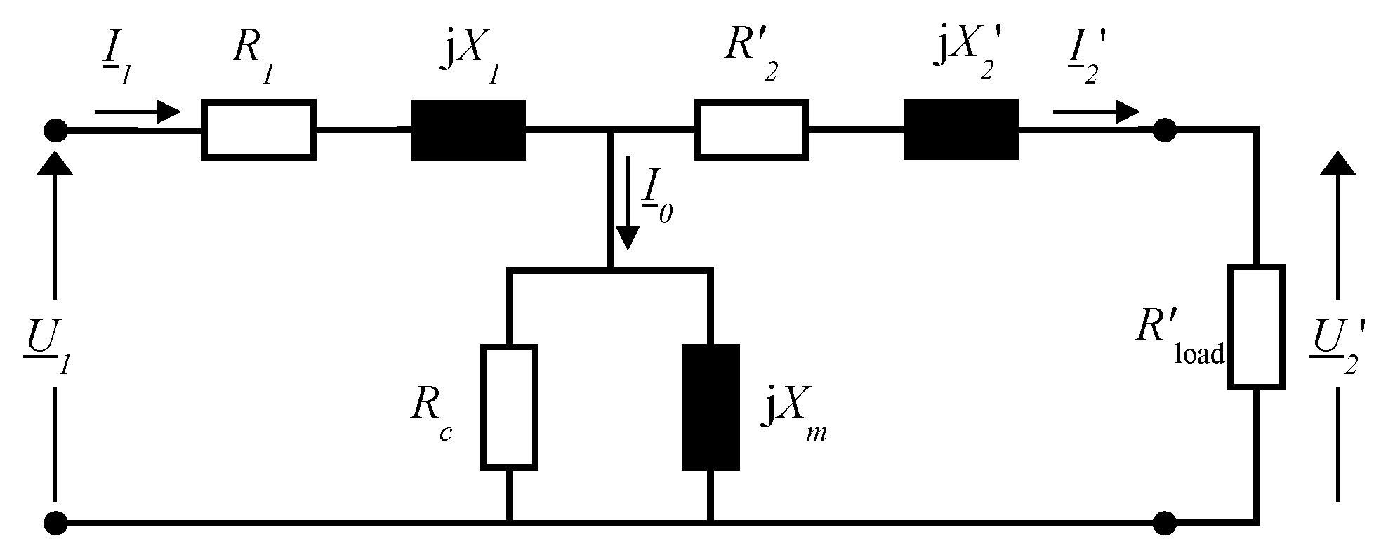
Section 2 provides a short description of the transformer equivalent circuit. COA is presented in Section 3. The application of COA for parameter estimation of transformer equivalent circuit is presented in Section 4. The experimental results and the COA-based estimation are presented in Section 5. Section 6 concludes the paper.

2. Transformer Equivalent Circuit

Transformer equivalent circuit referred to the primary side, with connected active load Rload, is presented in Figure 1 [9,10]. In this figure, R1, R2′, Rc, X1, X2′ and Xm represent primary coil resistance, secondary coil resistance referred to the primary side, core loss resistance, primary coil reactance, secondary coil reactance referred to the primary side, and magnetizing reactance, respectively. In the entire text, apostrophe ‘denotes the secondary value referred to the primary side.
The total impedance of transformer is as follows:
Z _ = Z _ 1 + Z _ 0 ( Z _ 2 + R l o a d ) Z _ 0 + Z _ 2 + R l o a d
where
Z _ 1 = R 1 + j   X 1 ,   Z _ 2 = R 2 + j   X 2 ,   Z _ 0 = R c j X m R c + j X m .
The primary current can be calculated as follows:
I _ 1 = U 1 Z _
whereas the secondary current is
I _ 2 = Z _ 0 Z _ 0 + ( Z _ 2 + R l o a d ) ( U _ 1 Z _ ) .
The secondary voltage is
U _ 2 = R l o a d I _ 2 .
Finally, the input power can be calculated as
P 1 = r e a l { I _ 1 U _ 1 } ,
and the output power is
P 2 = R l o a d | I _ 2 | 2 .

3. Chaotic Optimization Approach

Chaos is a form of an aperiodic long-term behavior that occurs under certain conditions in non-linear deterministic systems that exhibit a sensitive dependence on the initial conditions. It is about the steady state of dynamical systems described by ordinary differential equations or by iterative map. The behavior of the system depends on the value of its parameters. Parameter that can be changed is called the bifurcation parameter. Changing the bifurcation parameter leads to bifurcations i.e. qualitative changes in the state of the system. So, the system exhibits various forms of dynamic behavior, i.e., the trajectories can converge to the equilibrium point, the boundary circle or the chaotic attractor [25,26].
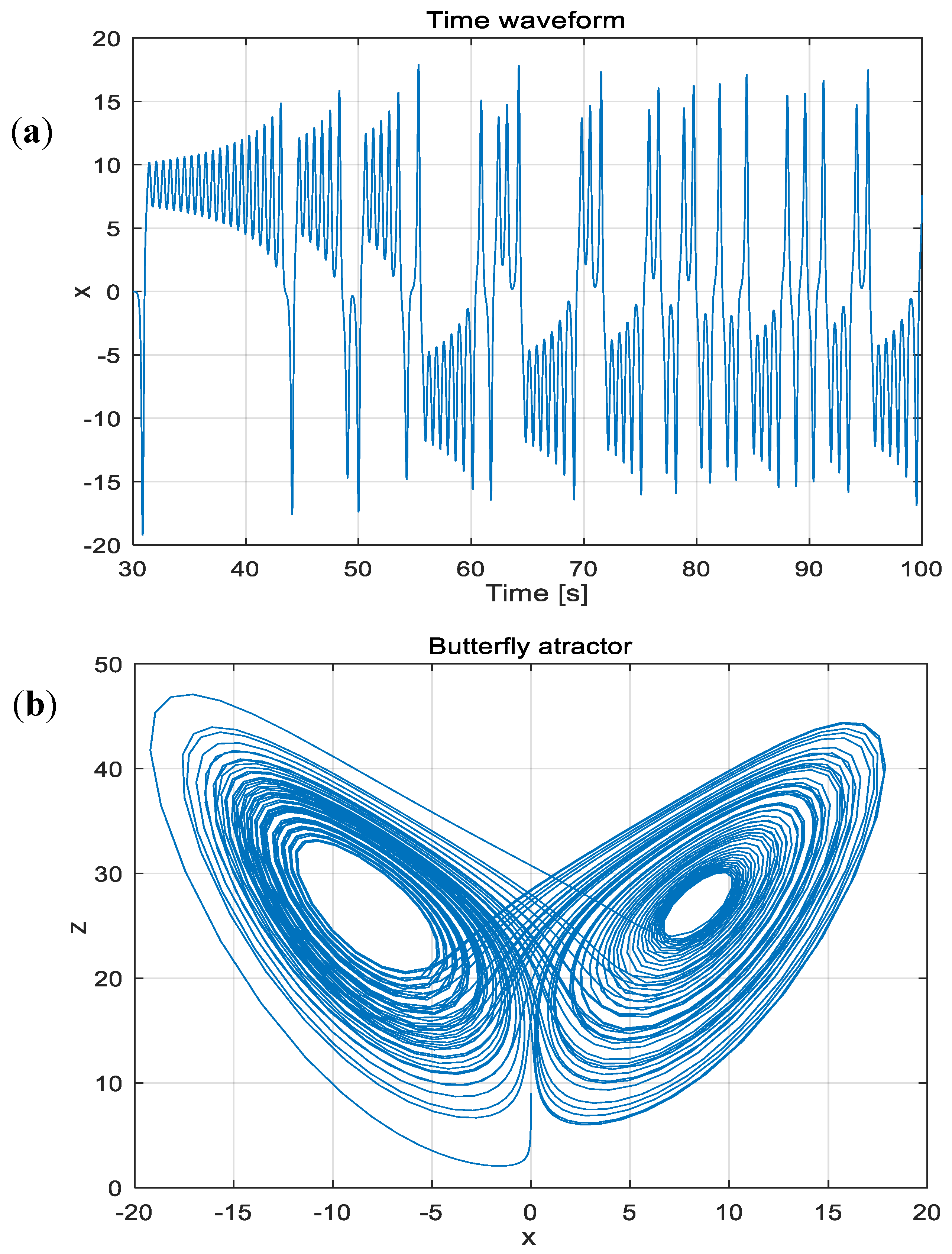
The characteristic property of chaotic dynamic systems is sensitive dependence on the initial conditions. If the evolution of such systems starts from two close points, after long enough time they will be arbitrarily far from each other. Time waveforms for the chaotic attractor are completely irregular and there is no repetition in any period of observation of the ultimate length. Although produced by deterministic equations, randomness in time-domain and long-term unpredictability in the state are present. The chaotic time waveform possesses a noise-like power spectrum.
One of the most famous chaotic systems is the Lorenz system [26]. Meteorologist Edward Lorenz has accidentally discovered sensitive dependence on initial conditions while modeling the atmospheric convention. He describes this complex system with three equations, since then known as the three-dimensional Lorenz system:
d x d t = σ ( y x )
d y d t = x z + r x y
d z d t = x y b z
with chaotic solutions for σ = 10, r = 28, and b = 8/3. The chaotic signal x(t) from the Lorenz system is shown in Figure 2a, and the corresponding chaotic attractor in the phase space (known as the butterfly attractor) is projected onto the x-y plane in Figure 2b.
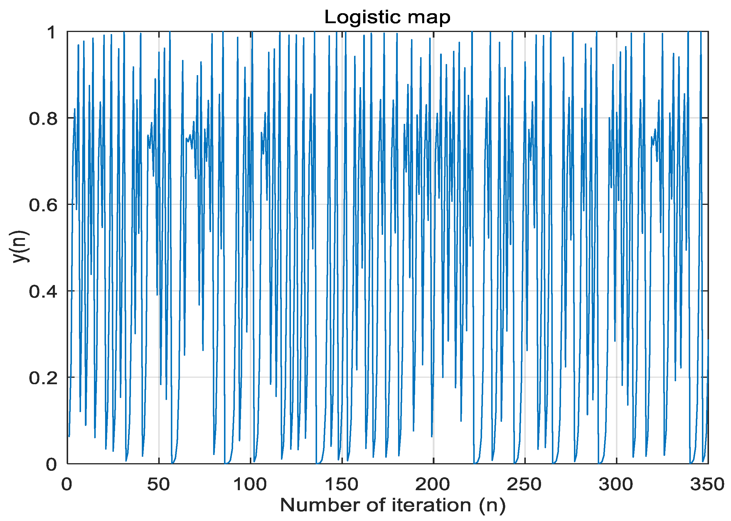
Chaotic behavior is also observed in iterative maps such as: Logistic map, Lozi map, Tent map and other [26]. In this paper, the chaotic sequence was obtained using the well-known Logistic map [26] given by
y k + 1 = r y k ( 1 y k )
where k represents the iteration number, and parameter r = 4. The logistic equation models a process that exhibits initial exponential growth with a nonlinearity that ultimately stops the growth. Most of the common features of chaos are manifest in this simple example. The chaotic signal obtained by Logistic map is shown in Figure 3. Details about chaotic systems can be found in [25,26].
The task of the chaotic optimization is to determine X which minimizes the fitness function F(X). The vector X = [x1,x2,…,xn] contains the variables x i [ L i , U i ] , limited to the lower (Li) and upper (Ui) permitted value. In this paper, for estimation transformer equivalent circuit parameters, we adopt n = 6 and X = [ x 1 , x 2 , x 3 , x 4 , x 5 , x 6 ] = [ R 1 , X 1 , R 2 , X 2 , R c , X m ] .
COA is based on the chaotic search [19,21]. Table 1 presents the search procedure, composed of two stages: global and local search. In local search, parameter λ is a corrective factor in determining the size of the search area around X*. Larger λ allows searching in larger area and vice versa.

4. Application of COA for Transformer Equivalent Circuit Parameters Estimation

This section is divided into two subsections. The first one covers the COA application in transformer parameters estimation based on the transformer nameplate data. The COA-based results are compared to that of the PSO, GA, ICA and GSA algorithms. The usage of COA for transformer parameters estimation based on the load data obtained from experiments is presented in the second subsection. In both subsections, the observed data (nameplate data and measured full load and primary current, secondary current, secondary voltage, input power and output power—load resistance characteristics) are taken from [9,10,11].
Computer simulations are implemented in MATLAB installed on PC with Intel(R) Core (TM) i3-7020U CPU @ 2.30 GHz and 4 GB RAM. The COA setup is Mg = 600, λ = 0.1 and ML = 300 in all simulations.

4.1. COA Application for Transformer Parameter Estimation Based on the Nameplate data

In order to confirm the accuracy and applicability of COA for transformer parameters estimation based on the nameplate data, we consider a 15kVA transformer with the following nameplate data: 15 kVA, one-phase, 2400V/240V, 50 Hz. The measured full load data are as follows: I1 = 6.2A, I2’ = 6.2A, V2’ = 2383.8V [9,10].
In this section, the problem of finding unknown parameters is reduced to the problem of minimization of the objective function (OF) which represents the combined squared difference between the measured (meas) and the estimated (est) values of the primary current (I1), secondary current referred to the primary side (I2′) and secondary voltage referred to the primary side (V2′), i.e. [9,10]:
O F = ( I 1 e s t I 1 m e a s ) 2 + ( I 2 e s t I 2 m e a s ) 2 + ( V 2 e s t V 2 m e a s ) 2
In (12), the estimated values are calculated by using (3)–(5). The transformer parameters, obtained by using standard ž-circuit and short-circuit tests, GA [9], PSO [9], ICA [10], GSA [10], as well as COA are presented in Table 2. The measured [9] and calculated values of the full load data are presented in Table 3.
From the results presented in Table 3, it can be observed that the average error for transformer data at full load, for secondary side, is the smallest for COA, which outperforms all other methods. Therefore, it can be concluded that the estimation of single-phase transformer parameters, from the nameplate data, has been successfully realized by using COA. Table 3 proves the applicability of the proposed COA-based approach for the parameter estimation of a single-phase transformer. Note that we have limited the parameters value around existing (existing values = values obtained by using GA, PSO, ICA and GSA—see Table 2). In addition, it can be seen that the COA parameters differ with existing solutions. In the case of non-limited values of parameters (results are: R1 = 2.0924 Ω, X1 = 1.0358 Ω, R2′ = 0.5234 Ω, X2′ = 0.081 Ω, Rc = 1.06∙107 Ω, Xm = 4.77∙106 Ω) we get I1 = 6.2002 A, I2′ = 6.1999 A, V2′ = 2383.8 V, i.e. we get better matching between the measured end the estimated full load data.

4.2. COA Application for Transformer Parameters Estimation Based on the Load Data Obtained from Experiments

In order to confirm the applicability of COA for transformer parameters estimation based on the load data obtained from experiments, we consider 2kVA transformer from [11] with the nameplate data as follows: 2 kVA, one-phase, 230V/115V, 50 Hz, whereas the measured load data are given in Table 4.
Table 5 shows the parameters of 2kVA one-phase transformer obtained by using COA and BFA [11]. For COA, we have used the following objective function:
O F 1 = i = 1 N ( ( I 1 e s t ( i ) I 1 m e a s ( i ) 1 ) 2 + ( I 2 e s t ( i ) I 2 m e a s ( i ) 1 ) 2 + ( V 2 e s t ( i ) V 2 m e a s ( i ) 1 ) 2 ) ,
where N represents the number of measured points (in this case, N = 6). The estimated values are calculated by using (3)—(5) (see Table 5).
Measured and estimated values of primary current, secondary current, secondary voltage, input power and output power, for transformer parameters estimated by using COA and BFA [11], are presented in Table 6. It can be seen that COA improves results compared with BFA. Difference between “actual”, BFA and COA parameters, is evident from Table 6.
The presented results show that COA can precisely estimate the transformer equivalent circuit parameters by using load data obtained from experiments, outperforming the BFA method in terms of estimation accuracy.

5. Experimental Results and Application of COA

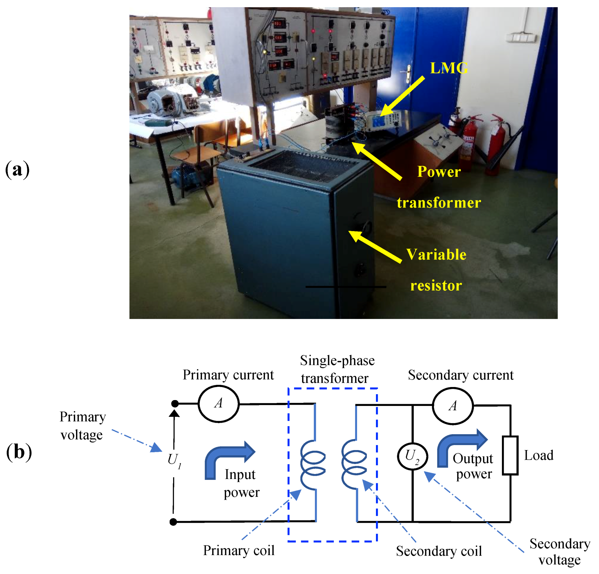
The experimental setup used for obtaining the data (primary current, secondary current, secondary voltage at full load, as well as primary current—load resistance, secondary current—load resistance, secondary voltage—load resistance, input power—load resistance and output power—load resistance characteristics) is composed of a one-phase transformer (KONCAR, 2 kVA, 220 V/110 V, 50 Hz) which supplies one variable resistor (maximum resistance 1000 Ω, and maximum current 25 A) (see Figure 4a—Experimental setup and Figure 4b—Electrical diagram of experimental setup). The variable resistor is used for transformer loading, i.e. it is used to vary the transformer load. All currents, voltages and powers were measured with power analyzer LMG (Leistungsmessgerät).
Firstly, on this transformer we have performed standard open-circuit and short-circuit tests as described in [1]. The transformer equivalent circuit parameters obtained by using results from open-circuit and short-circuit tests are presented in Table 7. After that, we have performed full load test, in order to be able to apply the method [9,10], which requires results from full load test and transformer nameplate data. By using data obtained from full load test (measured values of primary current, secondary current and secondary voltage are 8.95 A, 17.55 A and 105.5 A, respectively), as well as by using COA, we have obtained transformer parameters by applying method [9,10]. The estimated values of transformer parameters are also presented in Table 7.
Finally, by changing resistance of variable resistor, we have performed a set of experiments in order to obtain the transformer characteristics for different loads. All measured data for transformer loading are presented in Table 8. In order to obtain transformer equivalent circuit parameters, except (13), we have also proposed the following objective functions:
O F 2 = i = 1 N ( ( I p r i m e s t ( i ) I p r i m m e a s ( i ) 1 ) 2 + ( I sec e s t ( i ) I sec m e a s ( i ) 1 ) 2 )
and
O F 3 = i = 1 N ( ( I p r i m e s t ( i ) I p r i m m e a s ( i ) 1 ) 2 + ( I sec e s t ( i ) I sec m e a s ( i ) 1 ) 2 + ( V sec e s t ( i ) V sec m e a s ( i ) 1 ) 2 + ( P 1 e s t ( i ) P 1 m e a s ( i ) 1 ) 2 + ( P 2 e s t ( i ) P 2 m e a s ( i ) 1 ) 2 )
In (13)–(15) the estimated values are calculated by using (3)–(7).
The estimated transformer parameters, for the three objective functions, by applying COA, are presented in Table 7. The general conclusion is that all the applied methods yield close results. Therefore, it is expecting the good matching between measured and estimated output characteristics for all values of parameters (obtained by using open-circuit and short-circuit tests; obtained by using methods [9,10] and obtained by using COA and different objective functions).
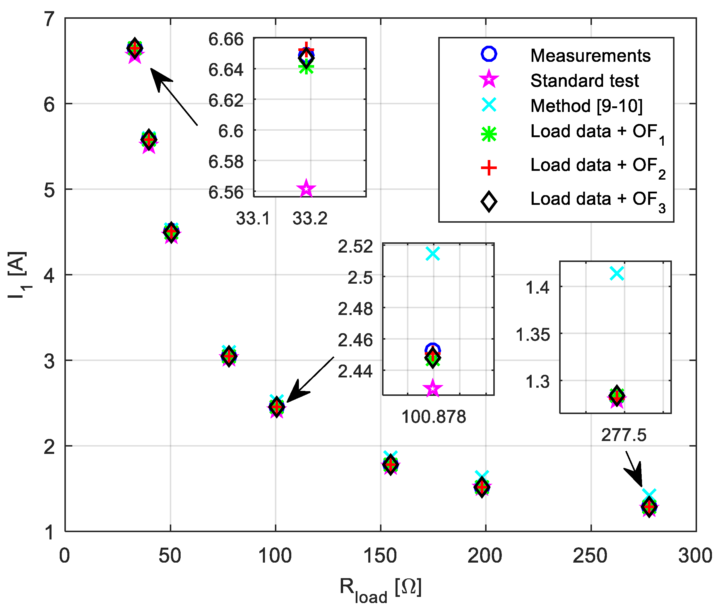
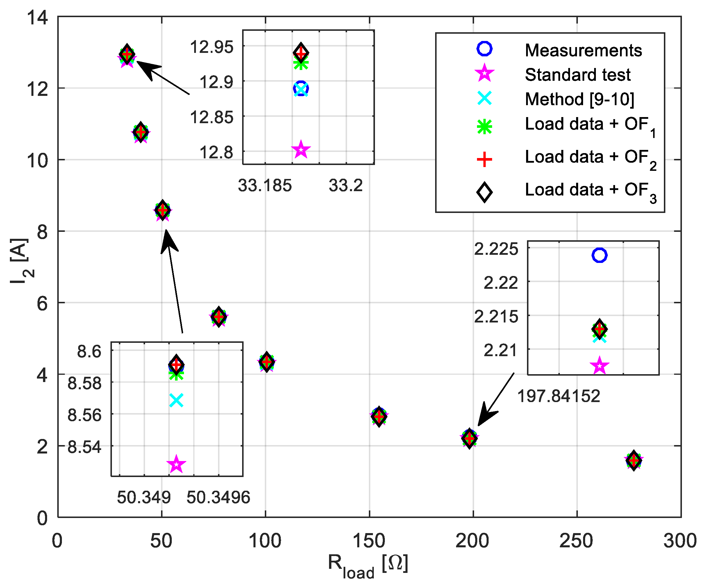
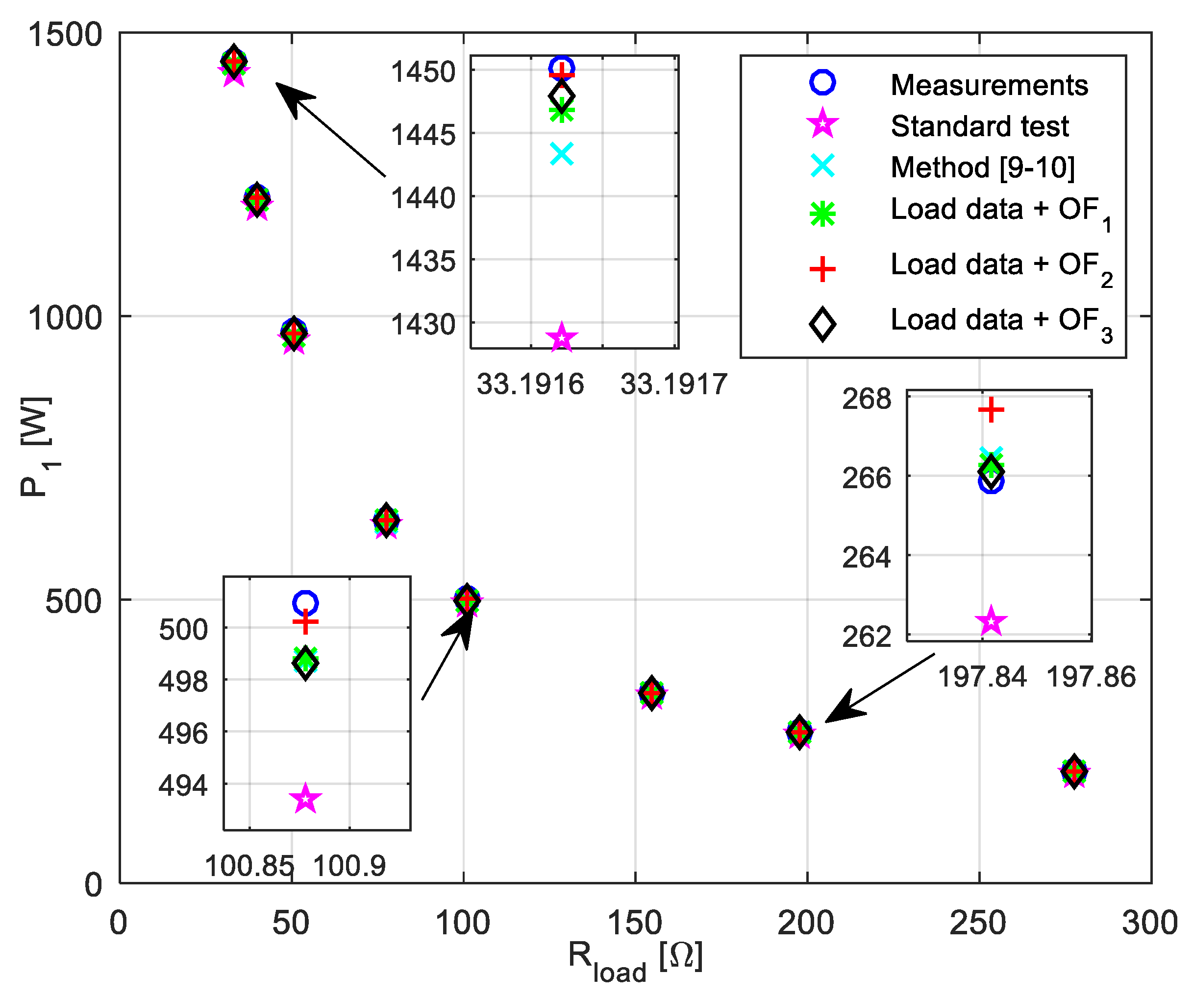
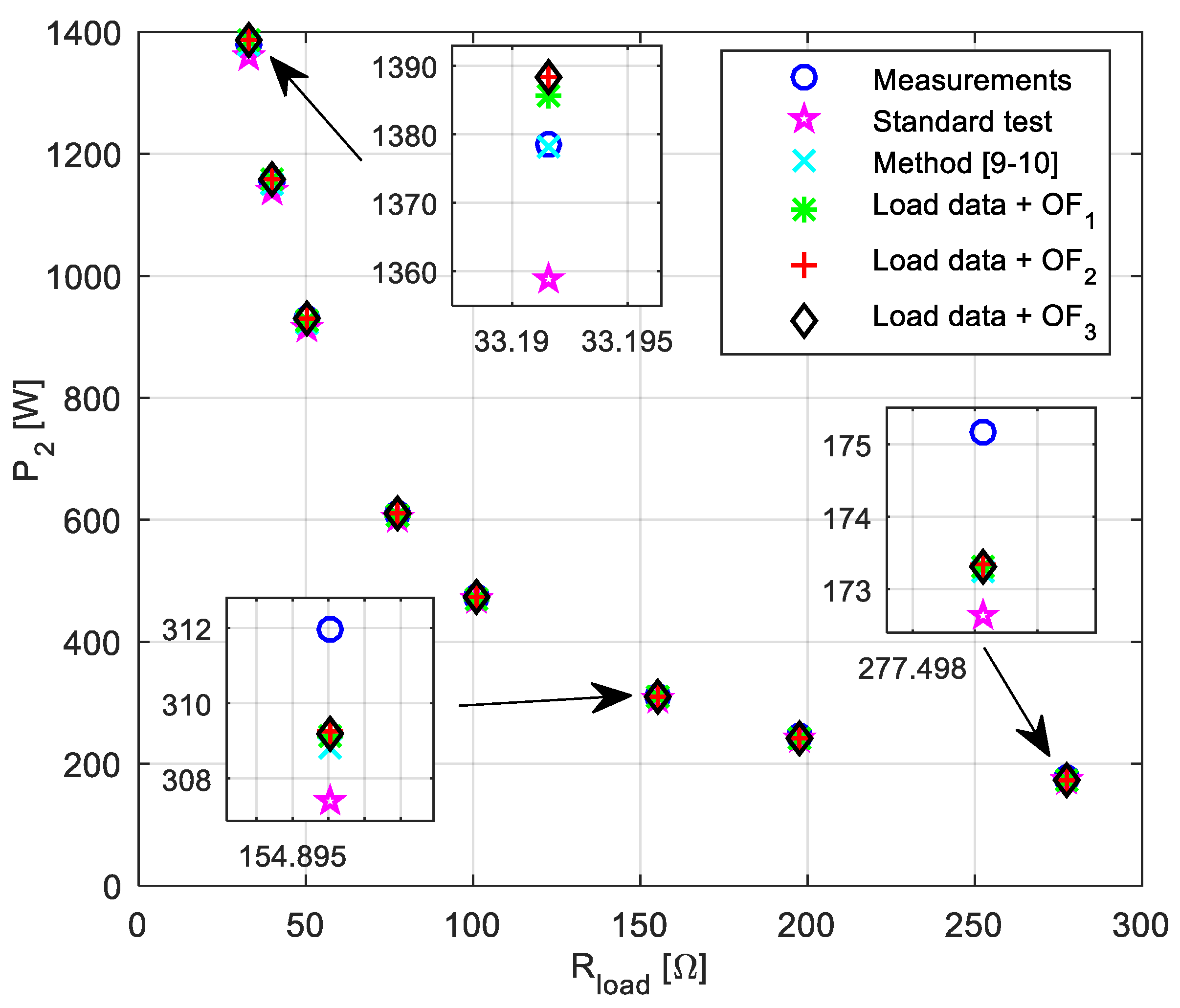
The measured and calculated (for parameters given in Table 7) primary current–load resistance, secondary current–load resistance, input power–load resistance and output power–load resistance characteristics are presented in Figure 5, Figure 6, Figure 7 and Figure 8, respectively. All presented characteristics are very close to each other (see zoomed parts in presented Figure 5, Figure 6, Figure 7 and Figure 8). However, using load data provides the best matching, whereas the worst matching is in the case of using parameters obtained from standard short-circuit and open-circuit tests.
By observing the presented results, it can be also concluded that [9,10] gives better result if the primary and secondary currents values are high (see Figure 5 and Figure 6). This is a consequence of the fact that this method is based on full load data (high value of current). However, for lower current values, there are certain deviations between the measured and estimated values.
On the other hand, parameters obtained by using load data and any of the proposed objective functions (13)–(15), in the whole load range, match the measured results very well (see for example Figure 7 and Figure 8). Therefore, for a precise estimation of the transformer equivalent circuit it is not needed to measure input (or output) active power or magnetizing current as proposed in [16].
Therefore, it is once again shown that the estimation of single-phase transformer equivalent circuit parameters by using COA, based on the nameplate and load data obtained from the experiments, provides very accurate results with reference to the measurements. Furthermore, all these testing’s have confirmed the applicability of COA in transformer parameters estimation. Also, regardless of the type of the objective function (which combines different variables), COA can precisely estimate transformer equivalent circuit parameters.

6. Conclusions

Chaotic Optimization Approach can be successfully applied for the single-phase transformer equivalent circuit parameters estimation. The efficiency of COA is compared to that of GA, PSO, ICA, GSA and BFA methods. The comparison is carried out on two transformers with different machine power and voltage level. The COA applicability has been also tested by using experimental results measured in a laboratory environment on 2 kVA single-phase transformer (standard short-circuit and open-circuit tests, full load test and different load tests). The measured results have been used for transformer parameters estimation by using COA with several objective functions. Regardless of the used data, COA can precisely estimate transformer equivalent circuit parameters. COAs outperform concurrent techniques as well as classical method based on open-circuit and short-circuit tests in terms of average error between the measured and the estimated values of the primary current, secondary current and secondary voltage at full load, and between the measured and the estimated output characteristics (for example output power–load characteristics, output current–load characteristics or similar).
In the future work, the attention will be focused on the usage of COA on three-phase transformer parameters estimation.

Author Contributions

Investigation, M.Ć.; Methodology, M.Ć.; and M.R.; Software, D.M. and V.R.; Supervision, M.Ć.; Writing—review & editing, M.Ć.

Funding

This research received no external funding.

Conflicts of Interest

The authors declare no conflict of interest.

References

  1. Kulkarni, S.V.; Khaparde, S.A. Transformer Engineering—Design and Practice; Marcel Dekker: New York, NY, USA, 2004. [Google Scholar]
  2. Chen, T.H.; Chang, Y.L. Integrated models of distribution transformers and their loads for three-phase power flow analyses. IEEE Trans. Power Deliv. 1996, 11, 507–513. [Google Scholar] [CrossRef]
  3. Soltau, N.; Eggers, D.; Hameyer, K.; De Doncker, R.W. Iron Losses in a Medium-Frequency Transformer Operated in a High-Power DC–DC Converter. IEEE Trans Magn. 2014, 50, 953–956. [Google Scholar] [CrossRef]
  4. Amoiralis, E.I.; Tsili, M.A.; Kladas, A.G. Transformer Design and Optimization: A Literature Survey. IEEE Trans Power Deliv. 2009, 24, 1999–2024. [Google Scholar] [CrossRef]
  5. Arunkumar, S.; Sandeep, V.; Shankar, S.; Gopalakrishnan, M.; Udayakumar, K.; Jayashankar, V. Impulse testing of power transformers—A model reference approach. IEE Proc. Sci. Meas. Technol. 2004, 151, 25–30. [Google Scholar] [CrossRef]
  6. Bogarra, S.; Font, A.; Candela, I.; Pedra, J. Parameter estimation of a transformer with saturation using inrush measurements. Electr. Power Syst. Res. 2009, 79, 417–425. [Google Scholar] [CrossRef]
  7. Abdulsalam, S.G.; Xu, W.; Neves, W.L.; Liu, X. Estimation of transformer saturation characteristics from inrush current waveforms. IEEE Trans. Power Deliv. 2006, 21, 170–177. [Google Scholar] [CrossRef]
  8. Shintemirov, A.; Tang, W.H.; Wu, Q.H. Transformer core parameter identification using frequency response analysis. IEEE Trans. Magn. 2010, 46, 141–149. [Google Scholar] [CrossRef]
  9. Mossad, M.I.; Mohamed, A.; Abu-Siada, A. Transformer Parameters Estimation from Nameplate Data Using Evolutionary Programming Techniques. IEEE Trans. Power Deliv. 2014, 29, 2118–2123. [Google Scholar] [CrossRef]
  10. Illias, H.A.; Moua, K.J.; Bakar, H.A. Estimation of transformer parameters from nameplate data by imperialist competitive and gravitational search algorithms. Swarm Evol. Comput. 2017, 36, 18–26. [Google Scholar] [CrossRef]
  11. Padma, S.; Subramanian, S. Parameter estimation of single-phase core type transformer using bacterial foraging algorithm. Engineering 2010, 2, 917–925. [Google Scholar] [CrossRef]
  12. Padma, S.; Subramanian, S. Bacterial Foraging Algorithm based Parameter Estimation of Three Winding Transformer. Energy Power Eng. 2011, 3, 135–143. [Google Scholar]
  13. Thilagar, S.H.; Rao, G.S. Parameter Estimation of Three-Winding Transformer Using Genetic Algorithm. Eng. Appl. Art. Intell. 2002, 15, 429–437. [Google Scholar] [CrossRef]
  14. Yilmaz, Z.; Oksar, M.; Basciftci, F. Multi-Objective Artificial Bee Colony Algorithm to Estimate Transformer Equivalent Circuit Parameters. Period. Eng. Nat. Sci. 2017, 5, 271–277. [Google Scholar] [CrossRef]
  15. Bhowmick, D.; Manna, M.; Chowdhury, S.K. Estimation of equivalent circuit parameters of transformer and induction motor using PSO. In Proceedings of the IEEE International Conference on Power Electronics, Drives and Energy Systems, Trivandrum, India, 14–17 December 2016. [Google Scholar]
  16. Bhowmick, D.; Manna, M.; Chowdhury, S.K. Estimation of Equivalent Circuit Parameters of Transformer and Induction Motor from Load Data. IEEE Trans. Ind. Appl. 2018, 54, 2784–2791. [Google Scholar] [CrossRef]
  17. Rahimpour, E.; Bigdeli, M. Simplified transient model of transformer based on geometrical dimensions used in power network analysis and fault detection studies. In Proceedings of the International Conference on Power Engineering, Energy and Electrical Drives, Lisbon, Portugal, 18–20 March 2009. [Google Scholar]
  18. Kazemi, R.; Jazebi, S.; Deswal, D.; de Leόn, F. Estimation of Design Parameters of Single-Phase Distribution Transformers from Terminal Measurements. IEEE Trans Power Deliv. 2017, 32, 2031–2039. [Google Scholar] [CrossRef]
  19. Rubežić, V.; Lazović, L.; Jovanović, A. Parameter identification of Jiles–Atherton model using the chaotic optimization method. Int. J. Comput. Math. Electr. Electron. Eng. 2018, 37, 2067–2080. [Google Scholar] [CrossRef]
  20. Coelho, L.S. Tuning of PID controller for an automatic regulator voltage system using chaotic optimization approach. Chaos Solitons Fractals 2009, 39, 1504–1514. [Google Scholar] [CrossRef]
  21. Jovanović, A.; Lazović, L.; Rubežić, V. Adaptive Array Beamforming Using a Chaotic Beamforming Algorithm. Int. J. Antennas Propag. 2016, 2016, 1–8. [Google Scholar] [CrossRef]
  22. Coelho, L.S.; Guerra, F.; Batistela, N.J.; Leite, J.V. Multiobjective Cuckoo Search Algorithm Based on Duffing’s Oscillator Applied to Jiles-Atherton Vector Hysteresis Parameters Estimation. IEEE Trans. Magn. 2013, 49, 1745–1748. [Google Scholar] [CrossRef]
  23. Wang, W.B.; Feng, Q.D.; Liu, D. Application of Chaotic Particle Swarm Optimization Algorithm to Pattern Synthesis of Antenna Arrays. Prog. Electromagn. Res. 2011, 115, 173–189. [Google Scholar] [CrossRef]
  24. Yang, D.; Li, G.; Cheng, G. On the efficiency of chaos optimization algorithms for global optimization. Chaos Solitons Fractals 2007, 34, 1366–1375. [Google Scholar] [CrossRef]
  25. Bertuglia, C.S.; Via, F. Nonlinearity, Chaos, and Complexity; Oxford University Press: Oxford, UK, 2005. [Google Scholar]
  26. Sprott, J.C. Chaos and Time-Series Analysis; Oxford University Press: Oxford, UK, 2003. [Google Scholar]
Figure 1. Transformer equivalent circuit referred to the primary side with connected active load Rload.
Energies 12 01697 g001
Figure 2. (a) Signal waveform from Lorenz system; (b) Butterfly attractor.
Energies 12 01697 g002
Figure 3. Chaotic signal obtained by Logistic map.
Energies 12 01697 g003
Figure 4. (a) Experimental setup, (b) Electrical diagram of experimental setup.
Energies 12 01697 g004
Figure 5. Primary current versus load resistance referred to the primary side characteristics.
Energies 12 01697 g005
Figure 6. Secondary current versus load resistance referred to the primary side characteristics.
Energies 12 01697 g006
Figure 7. Input power versus load resistance referred to the primary side characteristics.
Energies 12 01697 g007
Figure 8. Output power versus load resistance referred to the primary side characteristics.
Energies 12 01697 g008
Table 1. Chaotic search.
Global Search
Step 1Choose the parameter range.
Step 2Set the initial conditions yi(0) for i = 1,…, n.
Step 3Determine the maximum number of iterations Mg for the chaotic global search.
Step 4Form variables xi(k) = Li+yi(k)∙(Ui-Li), i = 1, …, n.
Step 5In the k-th iteration for X(k), calculate the fitness function F(X(k)).
Step 6Minimize the fitness function F yielding the vector X* which is input to the local search procedure.
Local Search
Step 1Determine the number of iterations for the local search ML.
Step 2In the k-th iteration, form variables xi(k) = xi* ± λ∙yi(k), i = 1, …, n. The sign + or—is selected randomly with equal probability.
Step 3In the k-th iteration for X(k), calculate the fitness function F(X(k)).
Step 4Minimize the fitness function F yielding the final vector X, whose coordinates are R1, X1, R2′, X2′, Rc and Xm are parameter estimates of the transformer equivalent circuit.
Table 2. Parameter values for 15kVA transformer from [9,10].
R1 [Ω]X1 [Ω]R2′ [Ω]X2′ [Ω]RC [Ω]Xm [Ω]
Actual *2.453.1422.22941050009106
PSO [9]2.254.0822.21.8526995179009
GA [9]2.763.4141.681.846970018951
ICA [10]231.8021200009200
GSA [10]23.111.812.261042819094.87
COA1.98542.61171.48511.520313101010074
* Data obtained from standard open-circuit and short-circuit tests—see [9,10].
Table 3. Full load data for 15 kVA transformer.
I1I2V2
Measurement6.26.22383.8
PSO *6.19796.16712371.1
Error ** PSO0.00210.032912.7
GA *6.19936.16782371.4
Error GA0.00070.032212.4
ICA *6.20516.17842375.5
Error ICA0.00510.02168.3
GSA *6.20816.17812375.3
Error GSA0.00810.02198.5
COA6.20796.18432377.7
Error COA0.00790.01576.1
* Values are calculated by using parameters given in Table 2. ** Error is calculated as the absolute difference between the measured and the estimated values.
Table 4. Load data of a single-phase transformer [11].
Load [%]V1 [V]V2 [V]I1 [A]I2 [A]P1 [W]P2 [W]
502261094.68.71000948.3
602251085.410.411801123.2
702251086.312.214001317.6
802231077.113.915681487.3
90223106815.717681664.2
1002231058.717.3919401826
Table 5. Parameter values for 15kVA transformer.
R1X1R2X2RCXm
Actual * [11]0.4280.210.5080.031437.5294.8
BFA [11]0.4280.430.4930.0241437.5294.226
COA **0.50480.60480.70700.01052012.6287.179
* Data obtained from standard open-circuit and short-circuit tests—see [11]. ** In this case we have limited the values of parameters around existing values. If the values of parameters have not been limited with some predefined constraints, we obtain the following R1 = 1.002 Ω, X1 = 0.8637 Ω, R2′ = 0.3308 Ω, X2′ = 0.0394 Ω, Rc = 5038 Ω and Xm = 170.9988 Ω.
Table 6. Measured and estimated values for a single-phase transformer [11].
Load [%] V1 [V]V2 [V]I1 [A]I2 [A]P1 [W]P2 [W]
50Measured2261094.68.71000948.3
BFA [11]226110.84.648.841032.9979.1
COA226110.064.578.781015.9966.8
Error * BFA1.80.040.1432.930.8
Error COA **1.060.030.0815.918.5
60Measured2251085.410.411801123.2
BFA [11]225109.95.4910.581223.41162.1
COA225109.045.416210.501203.81144.7
Error BFA1.90.090.1542.438.9
Error COA **1.040.01620.123.821.5
70Measured2251086.312.214001317.6
BFA [11]225109.46.3812.361423.81352.9
COA225108.516.286612.251401.01329.5
Error BFA1.40.080.1623.835.3
Error COA **0.510.01440.051.011.9
80Measured2231077.113.915681487.3
BFA [11]223108.17.2114.041597.11516.5
COA223107.017.100913.901571.11486.7
Error BFA1.10.111.0429.129.2
Error COA **0.010.000903.10.6
90Measured223106815.717681664.2
BFA [11]223107.68.1515.941808.81714.8
COA223106.448.027815.761778.31676.8
Error BFA1.60.150.2440.850.6
Error COA **0.440.02780.0610.312.6
100Measured2231058.717.3919401826
BFA [11]223107.29.0617.752010.71902.3
COA223105.908.910617.531975.51855.5
Error BFA2.20.360.3670.776.3
Error COA **0.90.21060.1435.529.5
* Error is calculated as the absolute difference between the measured and estimated values. ** If we use R1 = 1.002 Ω, X1 = 0.8637 Ω, R2′ = 0.3308 Ω, X2′ = 0.0394 Ω, Rc = 5038 Ω and Xm = 170.9988 Ω the matching between the measured and estimated values of the observed variables will be much better.
Table 7. Experimental results–Estimated values of parameters in [Ω].
R1X1R2X2RCXm
Standard test0.59650.37720.59650.37722494.8235.84
Method [9,10] + COA0.45190.11370.55280.20012129.6200.5981
Load data + COA + OF10.44140.19840.44590.50392132.3238.8488
Load data + COA + OF20.42750.20100.42640.50392011.3241.0986
Load data + COA + OF30.43210.22040.41690.49282149.8238.6202
* Standard test = open-circuit and short-circuit tests.
Table 8. Experimental results—Load data.
RLoad [Ω]V1 [V]V2 [V]I1 [A]I2 [A]P1 [W]P2 [W]
69.4220.23110.251.281.59195.7175.2
49.5220.09109.991.512.22265.9244.6
38.7220.30109.911.782.84334.2311.9
25.2220.25109.442.454.345009474.9
19.4219.95108.903.055.62640.9611.5
12.6220.19108.124.518.59972.1928.7
9.97219.95107.335.5810.761210.41155.0
8.32220.53106.966.6512.891450.11378.6

