Near Field Wireless Powering of Deep Medical Implants
by
 , ,
, ,
Tommaso Campi
1,*, 
Silvano Cruciani
1,
Valerio De Santis
1,
Francesca Maradei
2 and
Mauro Feliziani
1 1
Department of Industrial and Information Engineering and Economics, University of L’Aquila, 67100 L’Aquila, Italy
2
Department of Astronautics, Electrical and Energetics Engineering, Sapienza University of Rome, 00184 Rome, Italy
*
Author to whom correspondence should be addressed.
Energies 2019, 12(14), 2720; https://0-doi-org.brum.beds.ac.uk/10.3390/en12142720
Submission received: 25 June 2019
/
Revised: 12 July 2019
/
Accepted: 13 July 2019
/
Published: 16 July 2019
(This article belongs to the Special Issue Intelligent Wireless Power Transfer System and Its Application)
Abstract
:This study deals with the inductive-based wireless power transfer (WPT) technology applied to power a deep implant with no fixed position. The usage of a large primary coil is here proposed in order to obtain a nearly uniform magnetic field inside the human body at intermediate frequencies (IFs). A simple configuration of the primary coil, derived by the Helmholtz theory, is proposed. Then, a detailed analysis is carried out to assess the compliance with electromagnetic field (EMF) safety standards. General guidelines on the design of primary and secondary coils are provided for powering or charging a deep implant of cylindrical shape with or without metal housing. Finally, three different WPT coil demonstrators have been fabricated and tested. The obtained results have demonstrated the validity of the proposed technology.
1. Introduction
The wireless power transfer (WPT) technology can be applied to power or charge an active implantable medical device (AIMD). With this technology, the power can be transferred from the on-body transmitter to the in-body AIMD equipped with a receiver [1,2,3,4,5,6,7,8,9,10]. There are mainly two different approaches for this kind of application. The first one is based on the inductive coupling between two coils: the primary coil is worn by the patient, while the secondary coil is installed in the AIMD. The performance of the inductive power transfer is significantly improved using magnetic resonant coupling (MRC) between the primary and secondary coils at intermediate frequencies (IFs), i.e., 10 kHz–10 MHz [1,2,3,4,5,6,7,8].
The other popular WPT technology used for biomedical applications is based on midfield wireless powering (MWP) [9,10]. This last technology relays the properties of the field propagation inside biological tissues at radiofrequency (RF) that permits creation of a high-energy density region deep in tissues suitable to energize an AIMD.
Both WPT technologies have pros and cons. The MRC technology has the advantage of operating at IFs where the field attenuation in biological tissues is quite negligible. It can also be applied for high power transfer, but when powering deep implants it has a big limitation due to the exponential decay of the magnetic field produced by a planar coil. Therefore, when using a wearable small size coil, the inductive WPT technology cannot efficiently power deep implants, while it is very suitable for subcutaneous AIMDs, such as pacemakers [1,2,3,4,5,6]. On the other hand, the MWP technology [9,10] is very powerful for deep microimplants, but it is not very good for powering AIMDs in motion, with a variable position or with a metal housing.
A possible solution to power deep implant devices by MRC is the use of a primary coil with large dimensions that can generate a quite uniform magnetic field in a wide part of the body as the trunk or the head [7,8]. Currently, the use of large primary coils is applied to power only capsule endoscopes, which are characterized by low power and motion. Operating at IFs, the electromagnetic field deeply penetrates in the human body. This approach is, therefore, suitable for powering deep implants, no matter where they are placed or whether they are in motion or not. Unfortunately, the use of a large primary coil could have a significant impact on human safety, and hence it is necessary to assess the compliance with electromagnetic field (EMF) safety standards [11,12,13].
The starting point of the proposed method is the selection of the most suitable operating frequency that maximizes the WPT performance without exceeding the EMF safety limits. To this aim, an engineering solution for the MWP system has been addressed in [9,10], where the optimal frequency has been derived by a careful analysis of cost-benefit ratio. However, in MWP the frequency is much higher than 10 MHz and antennas are used for millimeter size receivers. Currently, no similar studies are available in the literature for MRC systems applied to power AIMDs at IFs. In the past, the frequency has been varied only to optimize the WPT performance without taking into account EMF safety issues [14].
The main novelty of the present study is the procedure to select the optimal frequency to wirelessly power deep implants using the near-field MRC technology. This result is achieved by maximizing the transferred power while being compliant with the EMF exposure limits.
Moreover, a new design of both on-body primary coil and in-body secondary coil is proposed. The electro-geometrical configuration of the transmitting coil is optimized to maximize the spatial region inside the human body where it is possible to power AIMDs in motion efficiently. General guidelines for the design of the secondary coil are also provided to enhance the transferred power reducing weight and size of a cylindrical shaped AIMD. The proposed application is particularly original as the considered AIMD can be with or without a metallic housing with or without ferrite cover, such as in the case of a leadless pacemaker that has been recently introduced in the market. Finally, three different WPT coil demonstrators have been fabricated and tested to verify the validity of the proposed method.
2. Wireless Power Transfer (WPT) System Design
2.1. Electromagnetic Field Model
To investigate the performance of a WPT system to power deep medical implants, it is necessary to use advanced electromagnetic field models due to the configuration complexity. When modeling a dispersive medium like the human body the electric and magnetic fields at IFs are described by:
where ω = 2πf is the angular frequency, A is the magnetic vector potential, Js the source current density, V the electric potential, μ the magnetic permeability and σ the electrical conductivity. The physical constants of biological tissues are frequency-dependent. Tissues properties at the frequency of interest can be found in [15].
Equation (1a) together with the current density continuity equation can be solved numerically by many commercial software tools, as those based on the finite element method (FEM).
The EMF safety of a WPT system requires the compliance with the basic restrictions (BRs) for the general public according to the ICNIRP guidelines and IEEE-TC95.1 standard. The BRs are given in terms of specific absorption rate (SAR) and internal electric field [11,12,13]. The electric field is obtained by (1c), while the SAR is calculated using the following expression:
where E is the rms value of the electric field and ρ the mass density of the considered body tissue.
2.2. Transmitting Side Design
The design of the transmitting system for powering or recharging a deep implant with no fixed position is based on the solution of the following two problems:
- (1)
- design of the primary coil that maximizes the working area inside the human body where the AIMD is located;
- (2)
- definition of the most suitable operational frequency that allows a deep penetration of the time-varying magnetic field without exceeding the EMF safety limits.
For the inductively-based WPT system, the main goal of the transmitting system design is to cover a large operational zone inside the human body where the magnetic field level must be higher than a prefixed value and spatially constant as much as possible. It is well known that the use of the Helmholtz coil is an adequate solution to obtain a nearly uniform magnetic field [16]. It consists of two identical circular solenoids, series-connected and coaxial, separated by a distance equal to the solenoid radius. The Helmholtz coil theory, developed for static field in air, can be used also in the presence of the human body and for time-variable fields [7,8]. To explain how it would be possible, we have to consider the behavior of the tissue physical constants in the frequency range 10 kHz–10 MHz. Their values, especially the relative permeability and low conductivity, make the human body quasi transparent to time-varying magnetic fields [17]. For these reasons, the Helmholtz coil theory is assumed to be valid also in the presence of the human body.
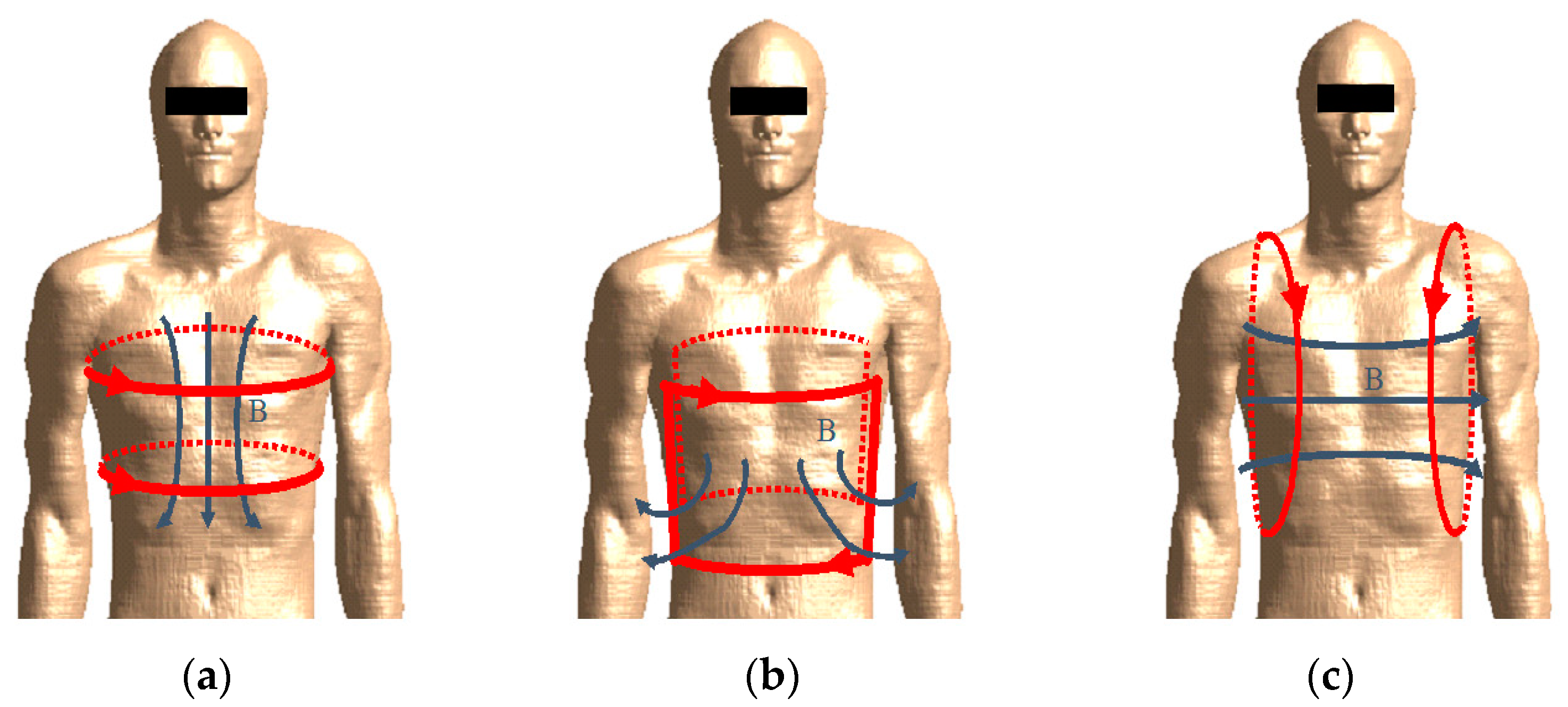
Taking inspiration from the Helmholtz coil theory, three possible configurations of two series-connected solenoids, purposely adapted for the human body, are considered as shown in Figure 1: top- bottom, front-back, right-left. The first configuration consists in winding the two solenoids around the trunk, one in a lower and the other in an upper position. The front-back configuration consists in positioning one coil in the front of the thorax and the other in the back. The right-left configuration finally consists in positioning both solenoids beside the trunk, one at the right side, and the other at the left side. The top-bottom configuration can be considered the most efficient, for the shape of the solenoids that can be simply worn as a belt or a chest strap, or integrated into a jacket. Obviously, their shape is no longer circular, but quite elliptical fitting the human body. Furthermore, the two solenoids are no longer identical and, in general, they can be adapted for any human body conformation. Brush spring contacts or small pieces of elastic wire can be used to create comfortable and adaptable coils.
Since the ratio radius/distance of the Helmholtz coil theory has no more sense for non-circular solenoids, the separation distance must be adjusted in order to obtain nearly uniform magnetic field in a target zone inside the human body. The resulting configuration will not exactly produce a uniform magnetic field, but it is more than adequate to assure field levels suitable to power deep implants in a wide volume, as well as to power/charge the battery of an AIMD in motion as a leadless pacemaker or similar devices. The only problem could be the reciprocal orientation of the primary coil worn by the patient and the secondary coil in the AIMD. Indeed, when the coil coupling is too low, the WPT efficiency and transferred power can rapidly degrade. This inconvenience can be overcome using multiple primary coils with different axis orientations.
Another important key factor in the design of deep implants powering system is the choice of the optimal frequency. It depends on many factors, such as: the electro-geometric configuration of the coils and of the human body composed of different biological tissues; the AIMD depth and orientation; the compliance with the BRs; the power to be transferred to the load. For simplicity, the choice of the optimal frequency is first treated assuming the following simplifications:
- -
- the excitation is given by two series-connected elliptical solenoids with top-bottom configuration assuming the human body in upright position;
- -
- the human body is assumed to be a simple multilayer cylinder with vertical axis.
The aim of the procedure is to maximize the induced voltage V in a single turn small loop S representing the secondary coil located inside the human body without exceeding the BRs. The open-ended induced voltage V in the loop is obtained by Faraday’s law of induction in the frequency domain as:
where ϕ is the magnetic flux produced by the magnetomotive force MMF = N1I1 generated by the primary coil with N1 turns and current I1, and linked with the loop area S. The magnetic flux ϕ in the human body is linearly dependent on the MMF and is given by:
where n is the unit normal vector to the loop area S.
The induced voltage V could be very large for high values of the MMF, but it must be limited in order to be compliant with the BRs of the human exposure standards. In the considered case of two series connected single-turn loops for the primary coil, we have N1 = 2. In the ICNIRP 2010 guidelines, the BRs for the general public are given in terms of internal electric field E averaged over a 2 × 2 × 2 mm3 cube for frequencies up to 10 MHz, while in the ICNIRP 1998 the BRs are in terms of localized SAR averaged over a 10 g contiguous tissue for frequencies higher than 100 kHz.
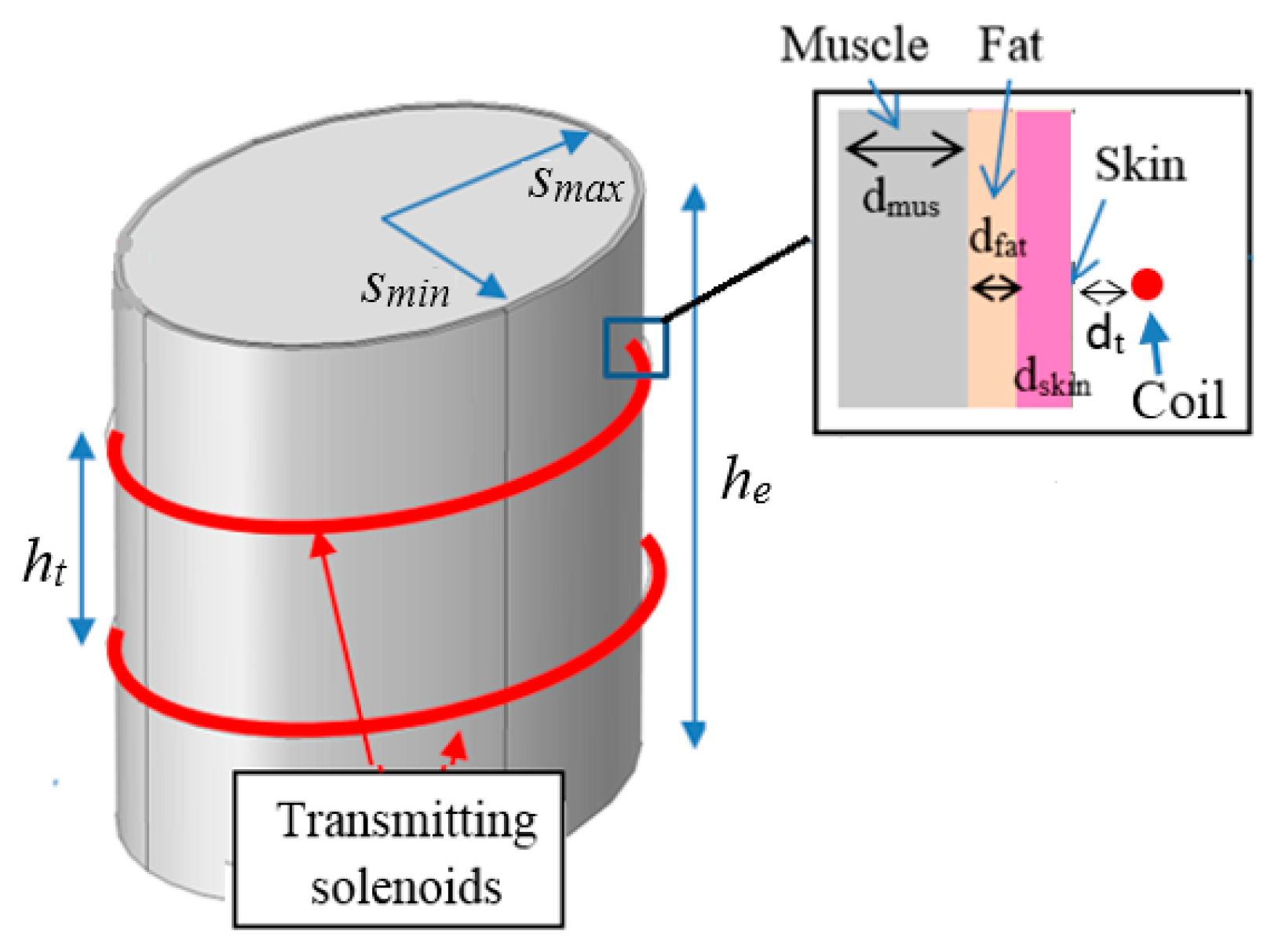
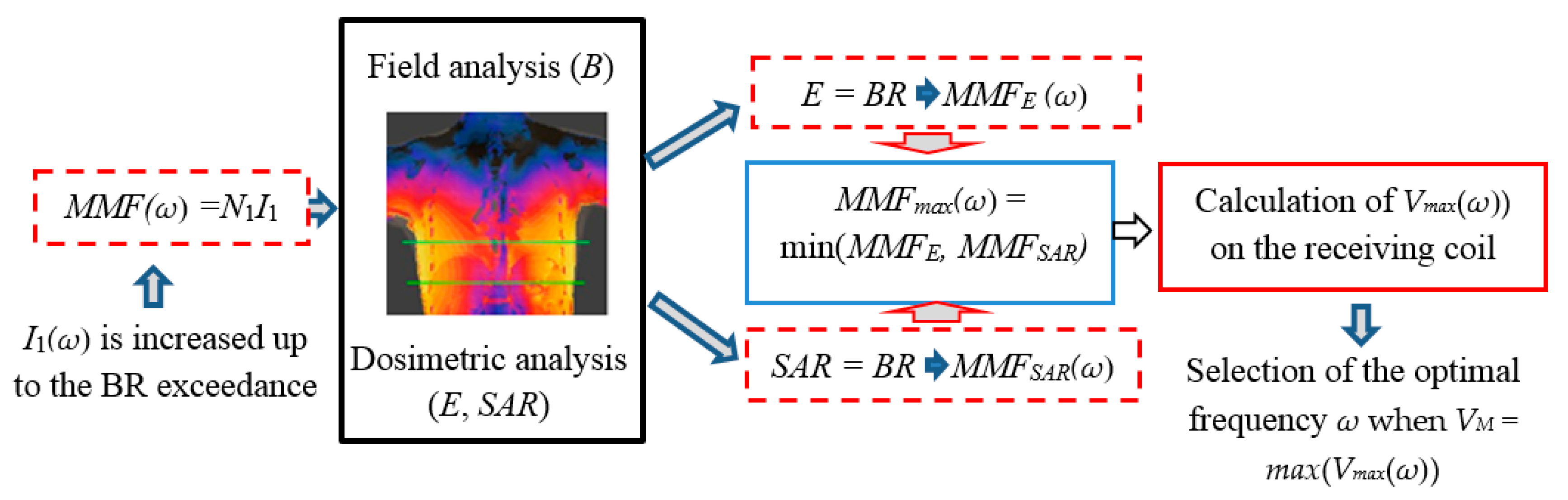
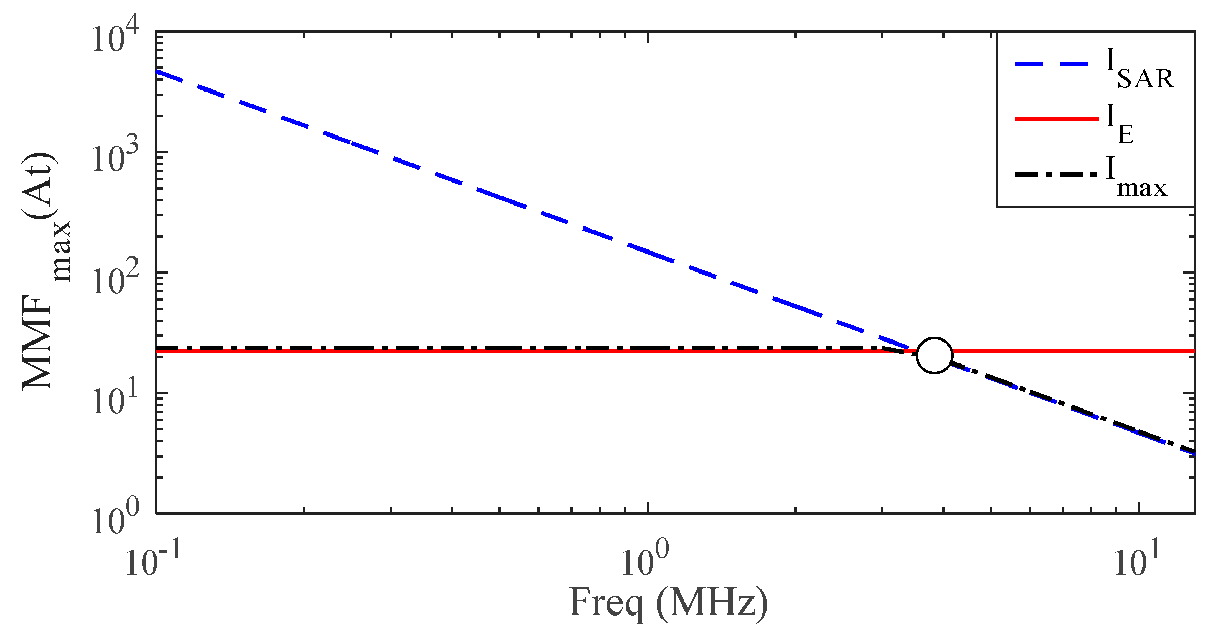
Finally, the IEEE-TC95.1 standard provides both in-situ electric field (averaged over a 5 mm length) and SAR (averaged over 10 g cubic tissue) in the whole frequency range under investigation. To find the maximum induced voltage V, the primary coil of the top-bottom configuration has been considered, as schematically shown in Figure 2 where the trunk is schematized by a multilayer elliptic cylinder with semi-major axis smax = 180 mm, semi-minor axis smin = 140 mm, and height he = 600 mm. The multilayer cylinder is made of three frequency-dispersive biological tissues: inner muscle covered by two thin external layers of fat (thickness dfat = 3 mm) and skin (thickness dskin = 2 mm). The dielectric properties of muscle and fat are taken from [15], while those of the skin are taken from [18]. The distance between the coil and the torso is assumed as dt = 2 mm, while that between the two series-connected elliptical solenoids is ht = 100 mm. The procedure to find the best frequency to power deep implants is described in the following, and schematically summarized in Figure 3. At a considered angular frequency ω, the 3-D configuration is analyzed by a FEM solver to calculate the magnetic flux density B produced by the unit current I1(ω) = 1 A flowing through the excitation coils with N1 turns. Then the current I1(ω) and, therefore, the excitation MMF(ω) = N1I1(ω), is increased in magnitude until the ICNIRP BRs are not exceeded inside the human body [5]. According to the previously mentioned safety standards, compliance with the BRs needs to be verified in terms of both the induced E-field SAR by two different dosimetric analyses. For each considered frequency f ≤ 10 MHz, a maximum MMFE(ω) is obtained by increasing I1(ω) such that the averaged (in a volume for ICNIRP guidelines, or along a line for IEEE standard) electric field E in the human body never exceeds the BR. In analogy, for f ≥ 100 kHz, a maximum MMFSAR(ω) is obtained by increasing I1(ω) such that the 10 g averaged SAR never exceeds the BR. For frequencies in the range 100 kHz ≤ f ≤ 10 MHz, the minimum value between MMFE(ω) and MMFSAR(ω) is taken as the maximum admissible excitation MMFmax = min(MMFE, MMFSAR) that assures compliance with both ICNIRP and IEEE BRs. The calculated maximum admissible excitation MMFmax(ω) is shown in Figure 4.
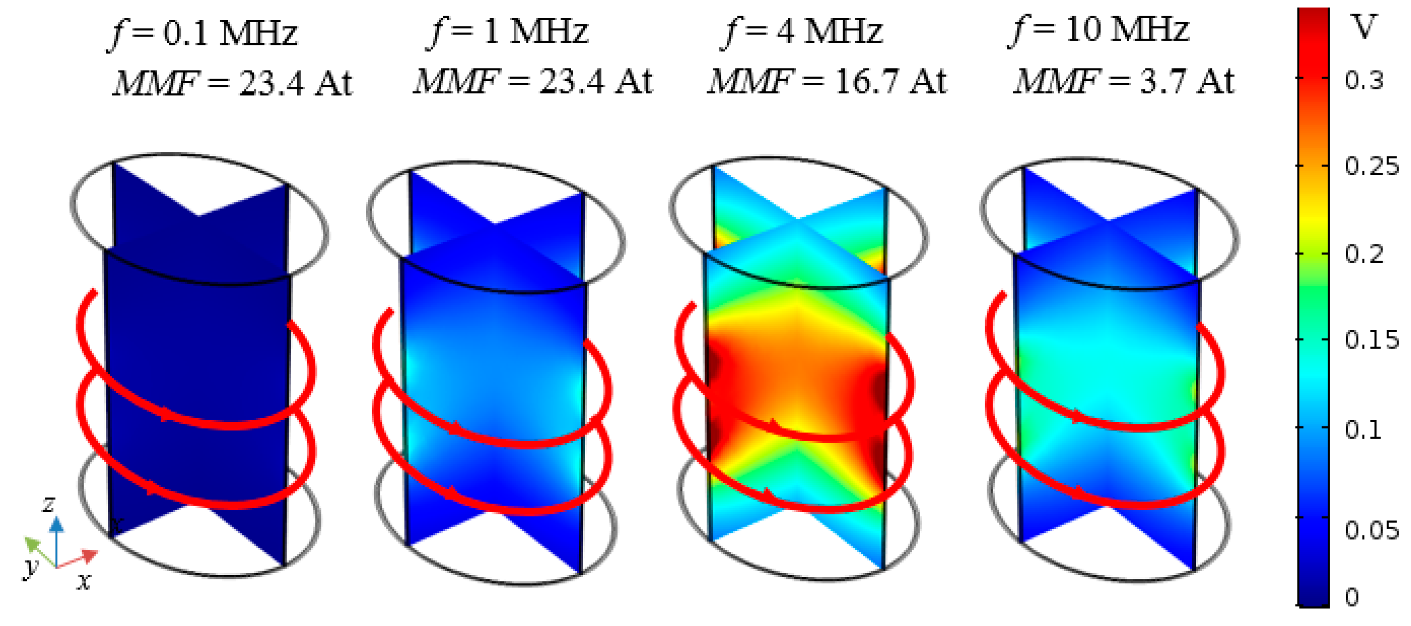
For the maximum admissible excitation MMFmax(ω), the maximum magnetic flux density Bmax(ω) is obtained, as well as the maximum induced voltage in a small loop area S given by Vmax(ω) = ω|Bmax|S. Obviously Vmax(ω) is obtained assuming Bmax and n to be parallel in (4). The maps of Vmax(ω) shown in Figure 5 are calculated at different frequencies when assuming the maximum admissible excitation MMFmax(ω), and the loop having a surface S = 1 cm2 occupying a variable position inside the human torso. The results show that the maximum voltage VM = max(Vmax(ω)) in the considered frequency range occurs at a frequency around 4 MHz and for MMFmax = 16.7 At. Therefore, f = 4 MHz is taken as the optimal frequency for the considered configuration.
The proposed procedure to find the optimal frequency is very general and can be applied for different coil-torso configurations. It is worth mentioning that the optimal frequency has been selected considering a simplified configuration, but it is a good starting point for the WPT design of a deep implant. Furthermore, to avoid small values of the induced voltage due to a bad orientation between B and n, other excitations can be adopted, e.g., biaxial or triaxial primary coils, combining some of the configurations shown in Figure 1.
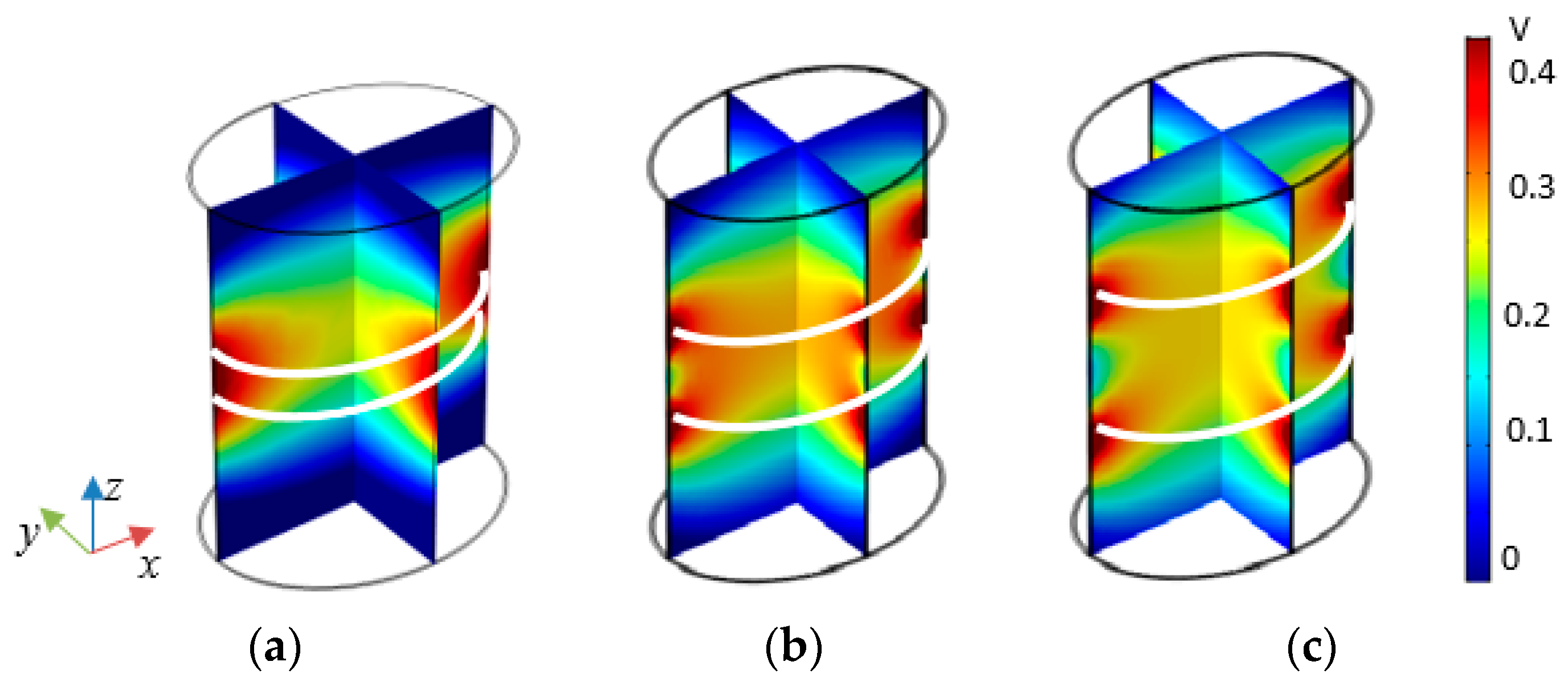
A further analysis is carried out to investigate whether the separation distance ht = 100 mm between the two solenoids was a good design choice. Thus, a sensitivity analysis is performed to maximize the working volume in the human body at f = 4 MHz when varying ht. Specifically, three separation distances are considered: a) ht = 50 mm; b) ht = 100 mm; c) ht = 150 mm. The maps of Vmax(ω) obtained for MMFmax(ω) excitations are shown in Figure 6 and point out as the field decreases significantly at the center of the torso for the configuration a), while a significant lack of field uniformity occurs in configuration c). Thus, the configuration b) confirms to be the best tradeoff between the size of working volume and the field uniformity and is, therefore, adopted in this work.
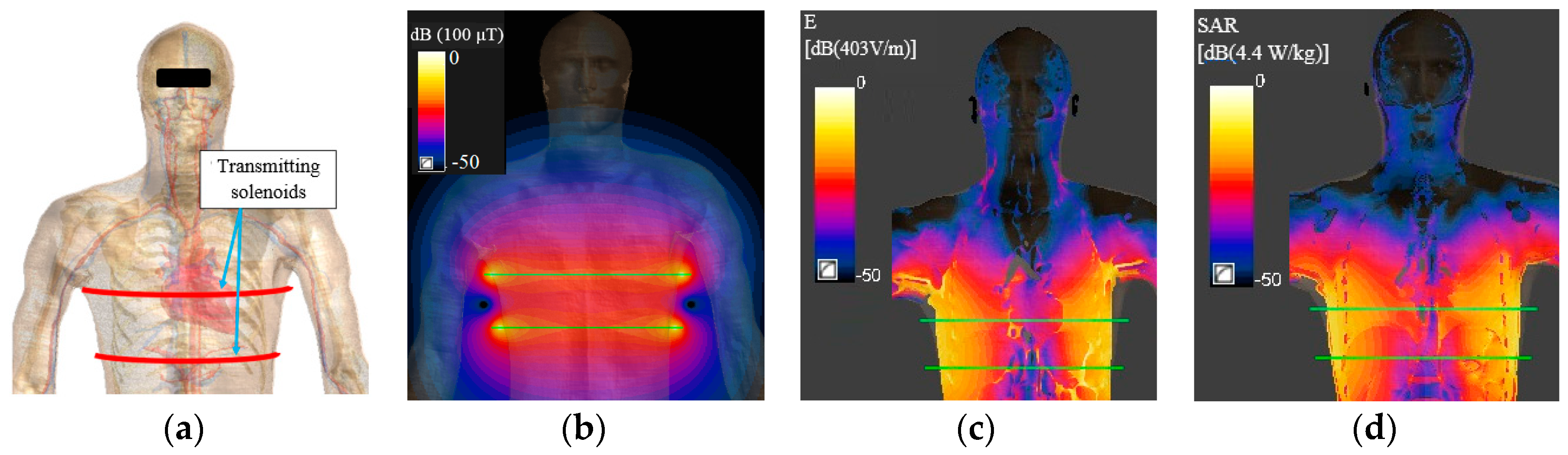
Once the best primary coil configuration and the optimal frequency have been selected, a more realistic torso model is considered such as a high definition human body model (HBM) of the virtual family (i.e., Duke) [19], as shown in Figure 7a. The HBM model with the coil source is modeled in Sim4Life [20], which allows the solution of the magneto quasi static (MQS) field equations for complex anatomies. With this tool, the maximum admissible MMFmax is accurately obtained. At 4 MHz, a value of MMFmax = 23.7 At is found to be compliant with BRs in terms of both E and SAR. As expected, this value is slightly higher than 16.7 At obtained with the simplified torso of Figure 2 due to the discontinuities in the HBM dielectric properties [21]. The magnetic field distribution inside the Duke model for MMFmax excitation is shown in Figure 7b. It should be noted that for the considered leadless devices it is not possible to verify the immunity to the external magnetic field because, in the current standard [22], at the considered frequency the limit is given in terms of peak-to-peak induced voltage Vpp at the input port of the pacemaker. However, the absence of the pacing leads makes the system very tolerant to the external magnetic fields. The E-field and SAR distributions are shown in Figure 7c,d, respectively. The maximum values of averaged internal electric field E and 10 g averaged SAR for ICNIRP guidelines and IEEE standard are reported in Table 1.
2.3. Receiving Side Design
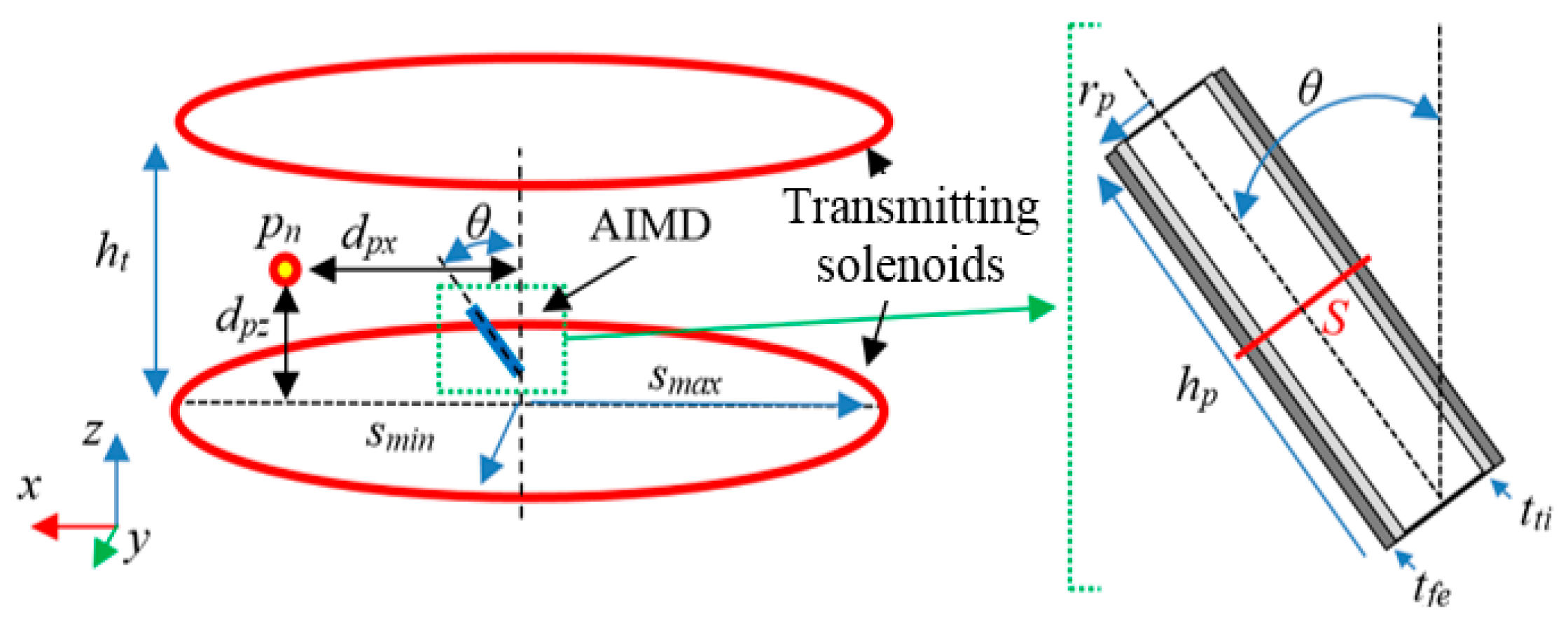
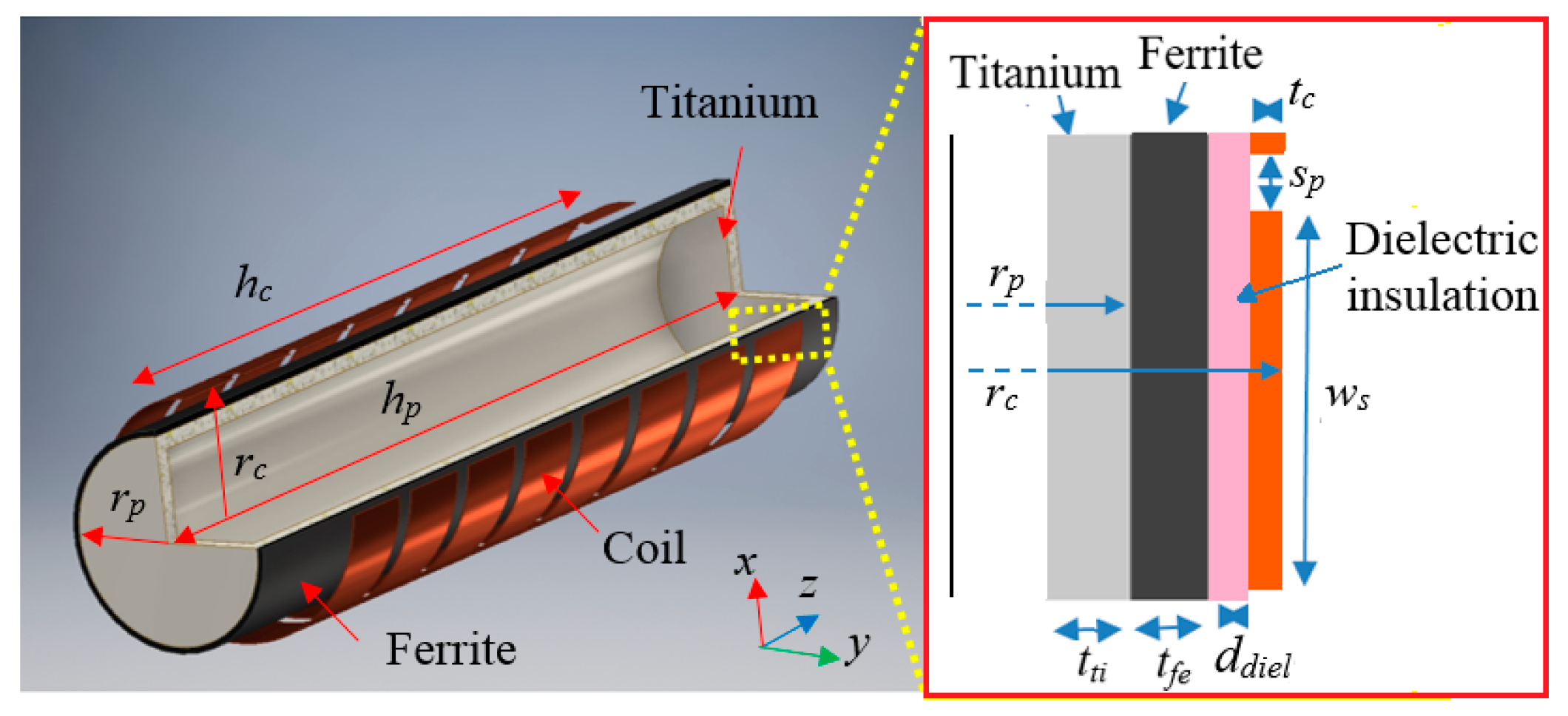
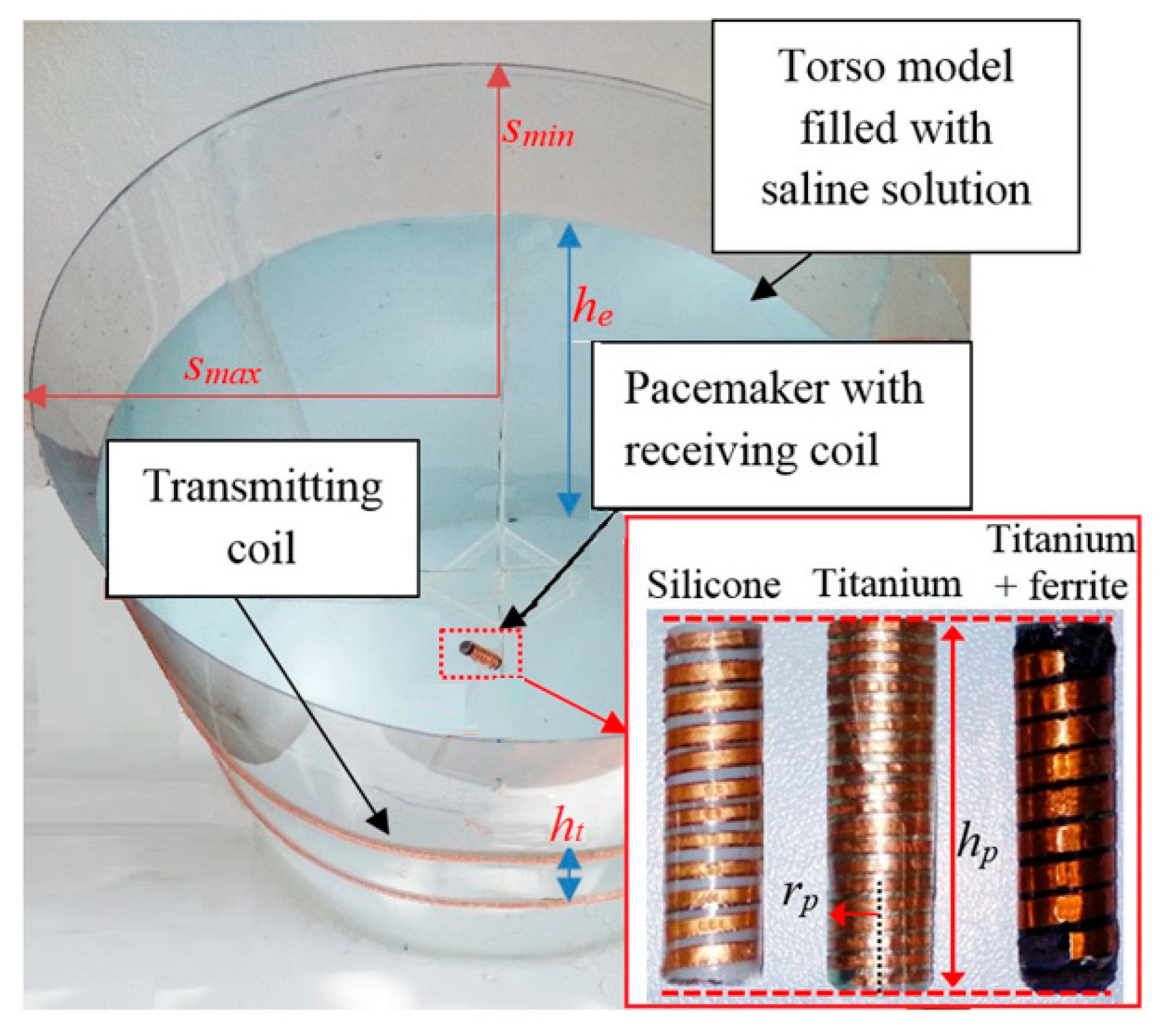
In order to improve the system performances, the design of the receiving coil is of paramount importance to take advantage of the magnetic field produced by the primary coil excitation. Some AIMDs, such as leadless pacemakers, have the housing made of titanium to improve electrical safety and to protect the human body from dangerous components as the battery. However, for WPT biomedical applications, the presence of conductive materials can be a strong limitation in terms of transferred power and safety. To overcome this issue, the conductive materials can be replaced, when possible, by other biocompatible non-conductive materials [10]. To analyze the effect of the housing material on the WPT technology, a comparative analysis for a generic AIMD of cylindrical shape is performed, as shown in Figure 8. The hollow cylindrical enclosure has radius rp = 3.5 mm, height hp = 30 mm and thickness tti = 0.5 mm. These dimensions are very close to that of a leadless pacemaker, selected here as demonstrator for the proposed technology. Specifically, three different materials are investigated for the housing:
- -
- Test case #1: silicone;
- -
- Test case #2: titanium;
- -
- Test case #3: titanium covered with an external layer of ferrite with thickness tfe = 0.4 mm.
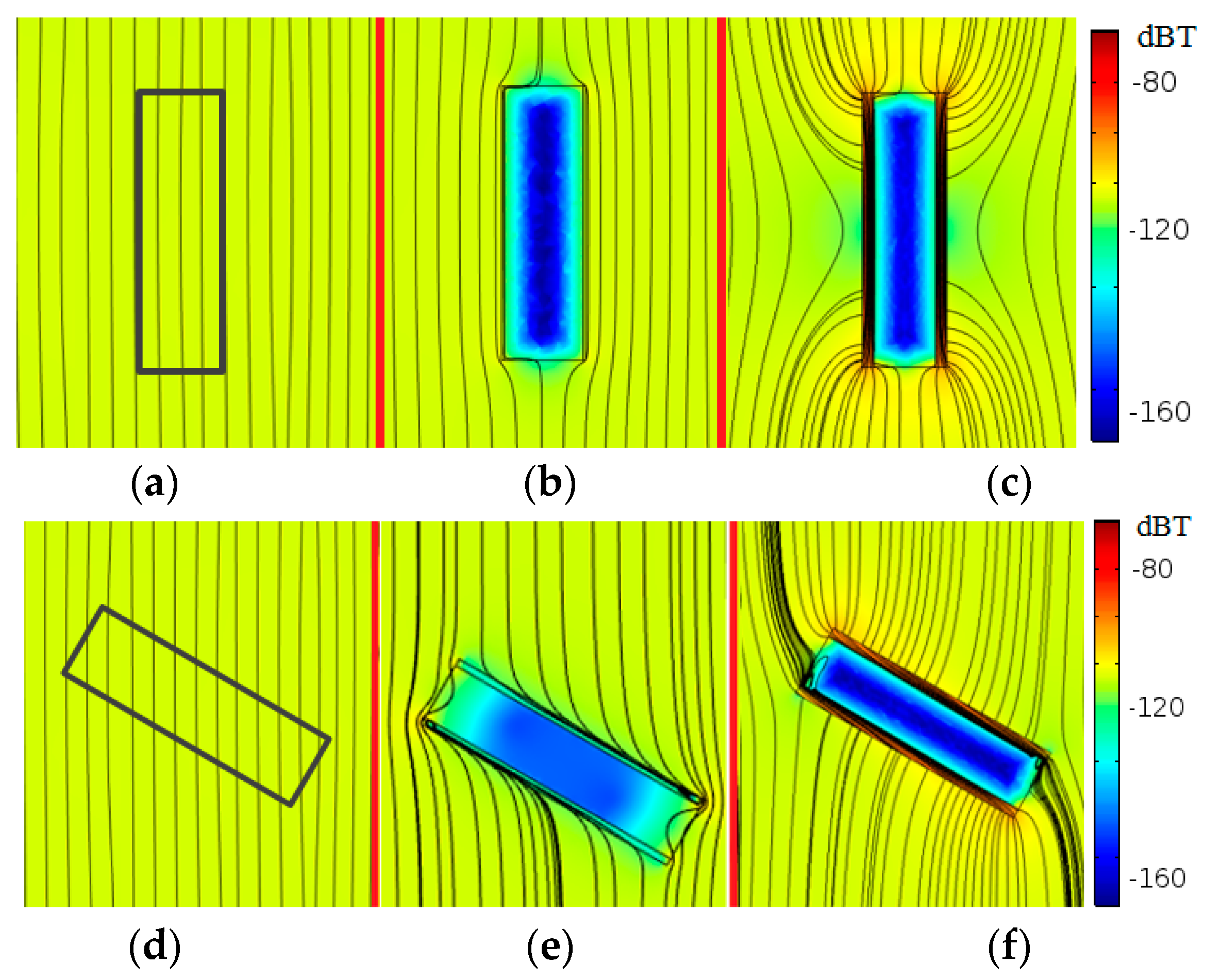
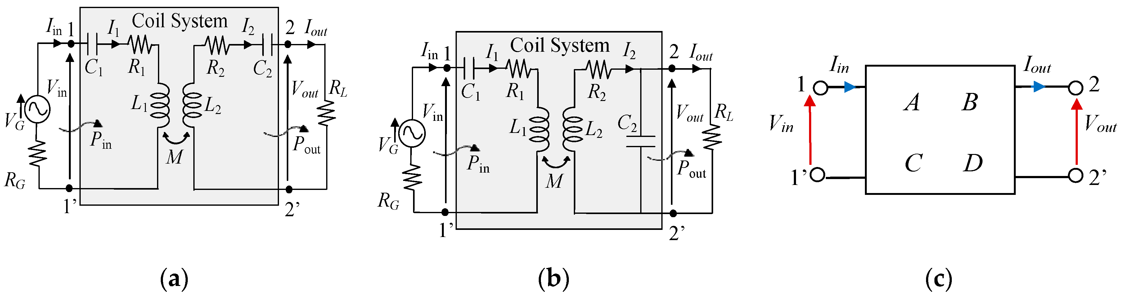
The primary magnetic field is generated by two elliptic large coils with semiaxes smax = 180 mm and smin = 140 mm vertically separated by a distance ht = 100 mm (i.e., the same as before). The effect of a coil rotation between the fixed primary coils and the secondary coil is investigated by varying the angle θ between the coil axes. The effect of a coil rotation between the fixed primary coils and the secondary coil is investigated by varying the angle θ between the coil axes. The primary and secondary coils are parallel for θ = 0°, but they are not necessarily coaxial. The distribution of the magnetic flux density and the magnetic flux lines are calculated for parallel (θ = 0°) and rotated (θ = 60°) conditions, as shown in Figure 9. The magnetic flux Φ linked with a circular surface having area S = 40 mm2 and placed in the center of the device (see Figure 8), is calculated for the three different configurations. The results reported in Table 2 show that the presence of the ferrite strongly improves the coil coupling and the tolerance to misalignment conditions. This is due to the ferrite layer that acts as a magnetic shield creating a preferential path for the flux lines [23,24]. When only a titanium housing is present, the incident magnetic field produced by the transmitting coil generates eddy currents that lead to a reduction of the magnetic coupling. For non-conductive materials, such as silicone, the incident magnetic field is unaltered. Therefore, the use of a ferrite layer covered with biocompatible silicone is the best solution from an electromagnetic point of view, although it is not always compatible with some medical exams, such as the magnetic resonance imaging (MRI). Thus, for devices with a more limited lifetime, such as an endoscope capsule, the use of ferrite is a good solution to improve system performances. On the other hand, the presence of ferrite could represent an important limitation for those devices that have an extended lifetime, such as a leadless pacemaker. In the following, a solution to overcome this limitation is proposed. The housing material of the receiving device has a noticeable impact on the magnetic field. Thus, an adequate design of the receiving coil is a key factor to obtain the maximum efficiency. Generally, the shape and dimension of the secondary coil are constrained by the external dimension of the considered device. Hence, an optimization is performed using the mathematical model of the WPT system. The electrical performances are derived by the analysis of the equivalent circuits shown in Figure 10a,b for series-series (SS) and series-parallel (SP) compensation topologies, respectively. In this figure, R1 and R2 are the primary and secondary coil resistances, L1 and L2 are the coil self-inductances, M is the coil mutual inductance, C1 and C2 are the compensation capacitors, VG and RG model the feeding source, and RL is the resistive load [1]. When considering the SS compensation of Figure 10a, with capacitances C1 = 1/(ω02L1) and C2 = 1/(ω02L2) to assure resonance condition at the resonance angular frequency , the currents on the primary and secondary coils are given by [25]:
The efficiency η, defined as the ratio of the active power Pout delivered to the load RL over the active power Pin at port 1-1′, is given by:
Similar equations can be easily derived for the SP compensation, but they are here omitted for brevity.
In order to generalize the analysis for any topology, the equivalent two port network representation shown in Figure 10c is considered, which is characterized by the frequency-dependent parameters A, B, C, D as:
By simple manipulations, the efficiency is then obtained as:
where the superscript * denotes the complex conjugate. The WPT system efficiency reaches the maximum value when . This condition is satisfied when,
The solution can be optimized by adequately designing the coils or by matching the load with an impedance matching network. The optimum efficiency is obtained introducing RL,opt given by (9) in (8). For the SS topology in resonance condition, RL,opt is given by:
For a given operational frequency f0, the maximum efficiency can be achieved by varying the coil configurations, i.e., R1, R2, M. The optimization variables of the secondary coil are the turns number N2, the intra-turn spacing sp and the width ws. The resistance R2, depending on the wire length and section, is consequently obtained. The optimal configuration can be initially found using simple analytical models. Then, it is further optimized using numerical and experimental tests.
To achieve the desired incident field on the secondary coil, the primary coil with the top-bottom configuration (see Figure 1a) must produce a MMFmax = 23.7 At. Assuming N1 = 6, grouped in 2 series-connected solenoids of 3 turns each and separated by a distance ht = 100 mm, the primary current I1 flowing in each turn is calculated as I1 = MMFmax/N1 ≈ 4 A that is an acceptable maximum current value. The primary coil is assumed to be a copper Litz wire. The secondary coil is spirally wound around the same cylindrical enclosure, with radius rp = 3.5 mm, height hp = 30 mm, and made by 3 different materials referred to the three test cases as previously described. The secondary spiral winding, shown in Figure 11, has external radius rc = 4.5 mm and winding height hc = 28 mm. The coil wire has rectangular cross section ws × tc with fixed thickness tc = 35 μm and variable width ws that depends on N2 as hc is kept fixed. The width ws is calculated as:
The intra-turn spacing sp is kept fixed to sp = 0.1 mm since it has not big relevance at the considered frequency [26]. A thin layer of dielectric insulation material with thickness ddiel = 0.6 mm is interposed between the coil and the housing.
The optimization is carried out to find the optimum N2 and the optimal compensation topology. The turns number of the secondary coil is varied in the range N2 = 5–30. For each value of N2, the circuit parameters extracted by FEM simulations are used to calculate the performances of the WPT system while keeping fixed the maximum primary current I1 = 4 A and the load resistance RL = 200 Ω [27].
2.4. WPT Electrical Performances
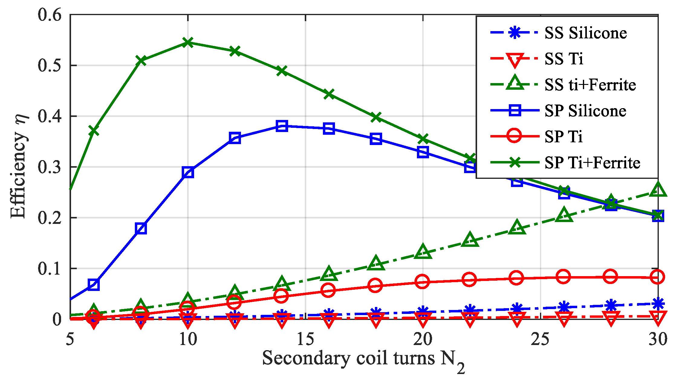
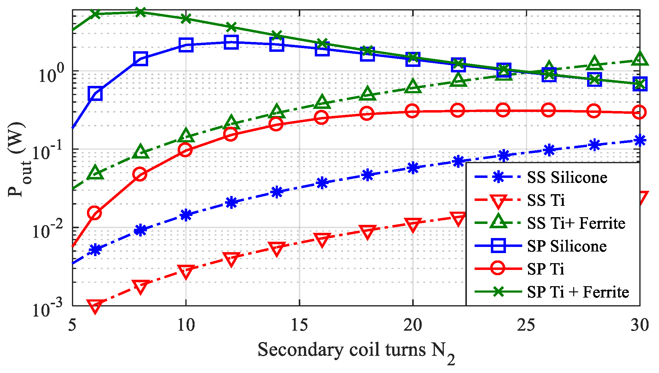
The efficiency for the three test cases when assuming the secondary coil placed in the center of the two primary solenoids is shown in Figure 12 considering both SS and SP compensation topologies. The corresponding maximum transferable power is shown in Figure 13. The results clearly show that the SP topology is the best in terms of both efficiency and transferred power Pout. Thus, only SP compensation will be considered in the following. The optimal transferred power is obtained for:
- -
- N2 = 12 for the test case #1 (silicone);
- -
- N2 = 20 for the test case #2 (titanium housing);
- -
- N2 = 8 for the test case #3 (titanium housing + ferrite).
The obtained results highlight the capability of the proposed solution to transfer a relatively large amount of power to the AIMD also for the test case #2 (titanium housing without any ferrite cover) obtaining a maximum output power Pout = 310 mW. Note that, in the case of a deep implantable device such as a leadless pacemaker, the required power is generally smaller than 10 mW [3,28], that is much lower than Pout.
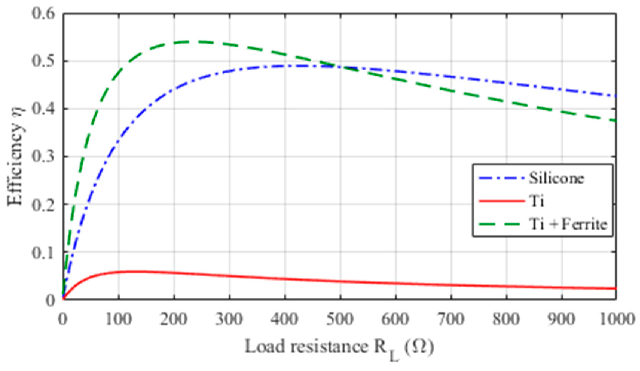
In order to investigate the influence of the load on the WPT performances, the analysis of the efficiency is carried out by varying RL in the range 0–1000 Ω for the three considered test cases. The obtained results are shown in Figure 14, highlighting as these WPT systems can operate very well for a wide range of RL values.
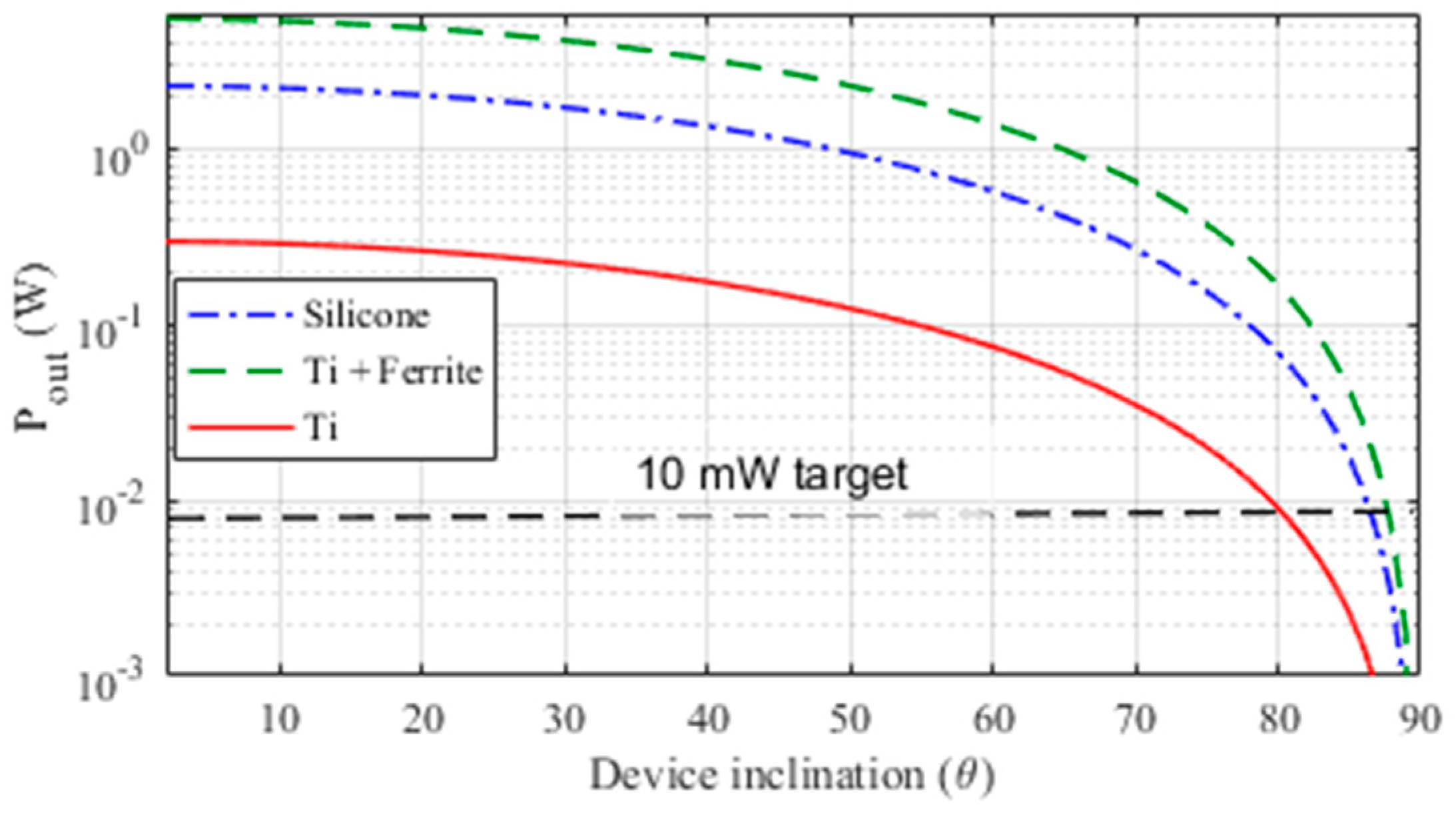
Finally, the tolerance of the WPT systems to misalignment conditions has been tested. This aspect is very important as the implantation position (mostly the angular alignment) changes with individual body conformations and possible motions of the AIMD. To this aim, the transferred power, when keeping fixed the primary current I1 = 4 A, is calculated for several inclination angles θ of the device axis respect to the primary coil axis. The results obtained shown in Figure 15 demonstrate the capacity of the system to deliver the target power of 10 mW up to an angle of θ = 80° for a device with housing made in titanium, and up to θ = 85° for the other considered test cases.
2.5. Thermal Analysis
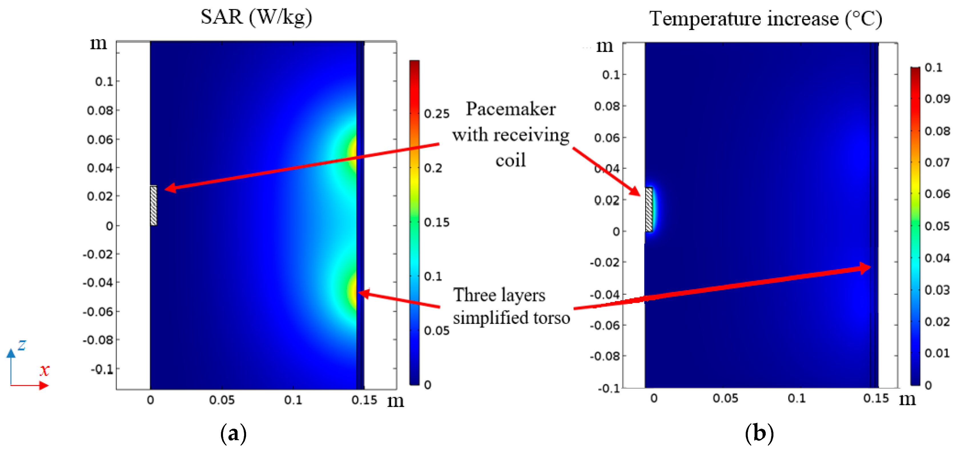
In the proposed application the thermal rise in tissues is mainly given by the electromagnetic field produced by the excitation coil current, while the heating produced by the receiving coil current and eddy currents in the housing are negligible due to the very low output power (10 mW) delivered to the secondary circuit. For this reason, the calculation of the temperature increase adopting the realistic HBM presented in Section 2.2, was performed considering only the electromagnetic field produced by the primary coil current. To validate this assumption, a thermal analysis adopting the simplified torso model of Figure 2 is adopted, introducing also the secondary coil and the titanium housing (test case #2). Note that test case #1 (silicone) and test case #3 (titanium covered by ferrite) will produce less eddy currents and thus heating, as explained in Section 2.3. The bio-heat equation (BHE) is numerically solved to predict the temperature increase in the biological tissues and to calculate the temperature distribution inside the human body tissues exposed to electromagnetic fields after 6 min of operation [2]. The maps of SAR and temperature increase for this configuration for a given output power Pout = 10 mW are shown in Figure 16 where a very low tissue heating, well below 0.1°, can be observed.
3. WPT System Demonstrator
3.1. Electrogeometrical Configuration
Three WPT secondary coil demonstrators with the same configurations adopted in the simulations have been realized to validate the numerical results. The secondary coils are wound around a cylinder with radius rp = 3.5 mm and height hp = 30 mm with the following specifications:
- -
- Test case #1: N2 = 12, rc = 4.5 mm, ws = 1.9 mm, hc = 28 mm.
- -
- Test case #2: N2 = 20, rc = 4.5 mm, ws = 0.9 mm, hc = 28 mm.
- -
- Test case #3: N2 = 8, rc = 4.5 mm, ws = 3 mm, hc = 28 mm, MnZn ferrite [11] with thickness tfe = 0.4 mm.
The devices, always covered by an insulation layer to assure biocompatibility, are assumed to be at point pn with dpx = 50 mm and dpz = 50 mm (see again Figure 8). To reproduce the presence of biological tissues, the device under test is immersed in a saline solution (0.9% solution of sodium chloride and water) as described in [29]. In all test cases, the primary coil is the same as described in the previous sections (two series connected elliptical solenoids with 3 turns each). The secondary coil demonstrators and the measurement setup are shown in Figure 17.
3.2. Numerical and Experimental Results
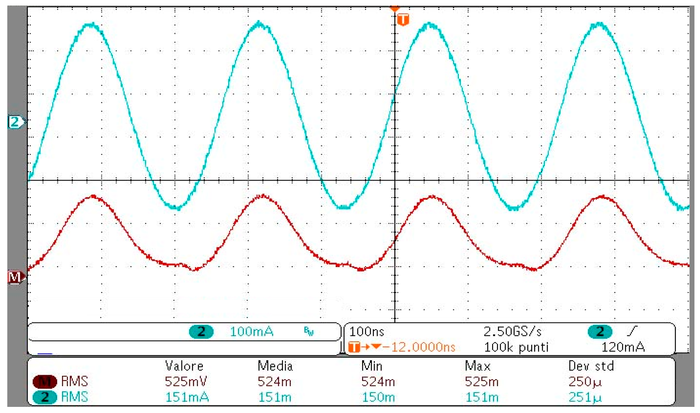
First, the lumped circuit parameters of the WPT system are numerically extracted by a field simulation [1]. Then, after fabrication, they are tested using a Keysight 4285A Precision LCR Meter. The measured and calculated circuit parameters are compared for aligned primary and secondary coils (θ = 0°). The calculated primary coil self-inductance is L1 = 18.8 µH and the measured one is L1 = 18.1 µH, while the self-resistance value is obtained from Litz wire datasheet as R1 = 350 mΩ. The values of the measured and calculated lumped parameters of the secondary coil are reported in Table 3. The SP compensation capacitors C1 and C2 are obtained as C1 = 1/(ω02(L1 − M2/L2)) and C2 = 1/(ω02L2). The output power, the current flowing into the primary and secondary coils and the efficiency are measured and calculated. In the experimental test, the WPT systems are driven by a class E inverter that permits to amplify the generated signal. The transferred power is adjusted by varying the DC voltage level at the input of the inverter. A shunt resistor in series between the inverter and the transmitting coil is used to measure the input current on the system.
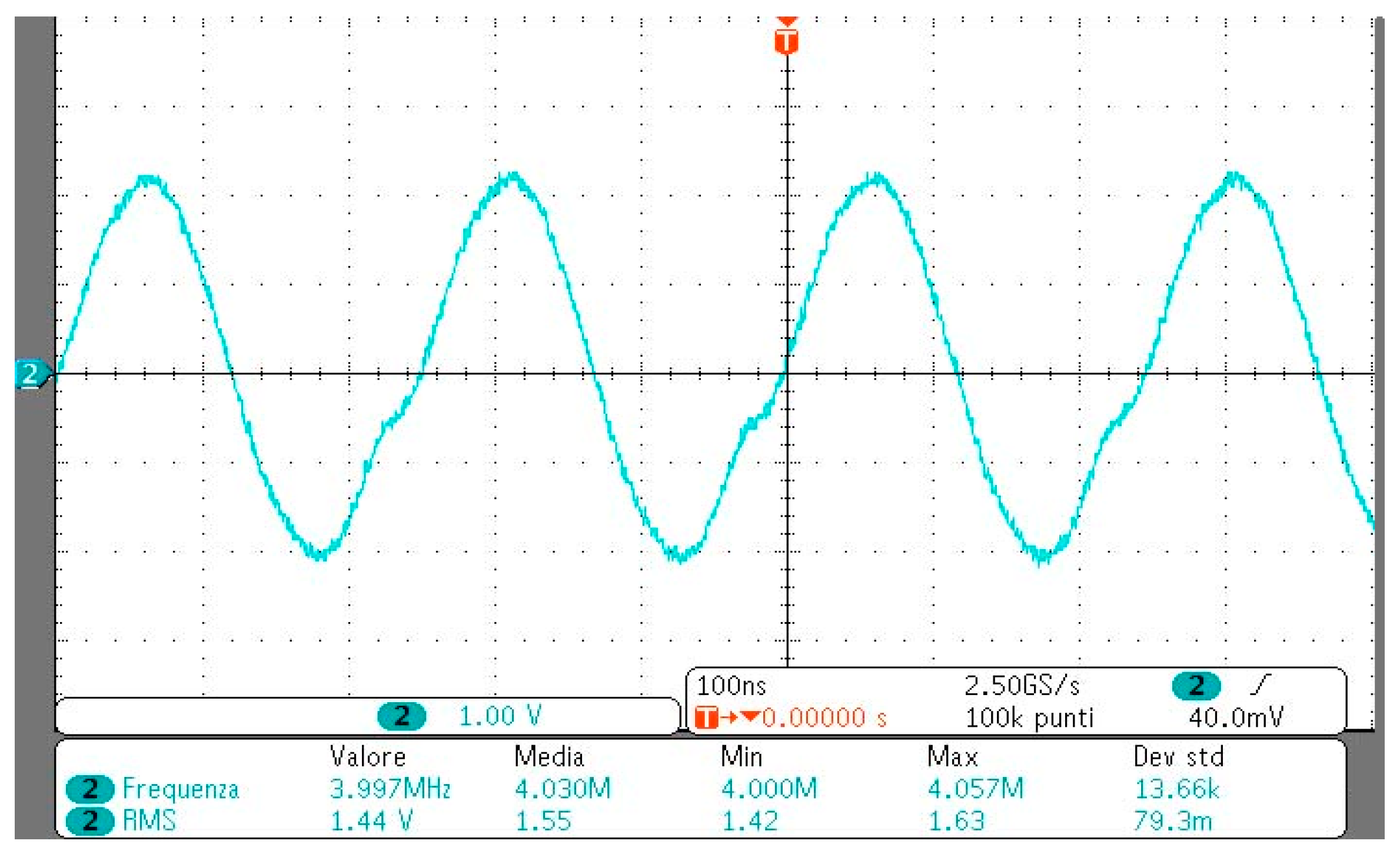
On the receiving side, the compensation capacitor and the resistive load are installed inside the pacemaker and insulated using silicone. To measure the output power, a shielded twisted cable is used to connect the load resistor of the device to a high input impedance oscilloscope.
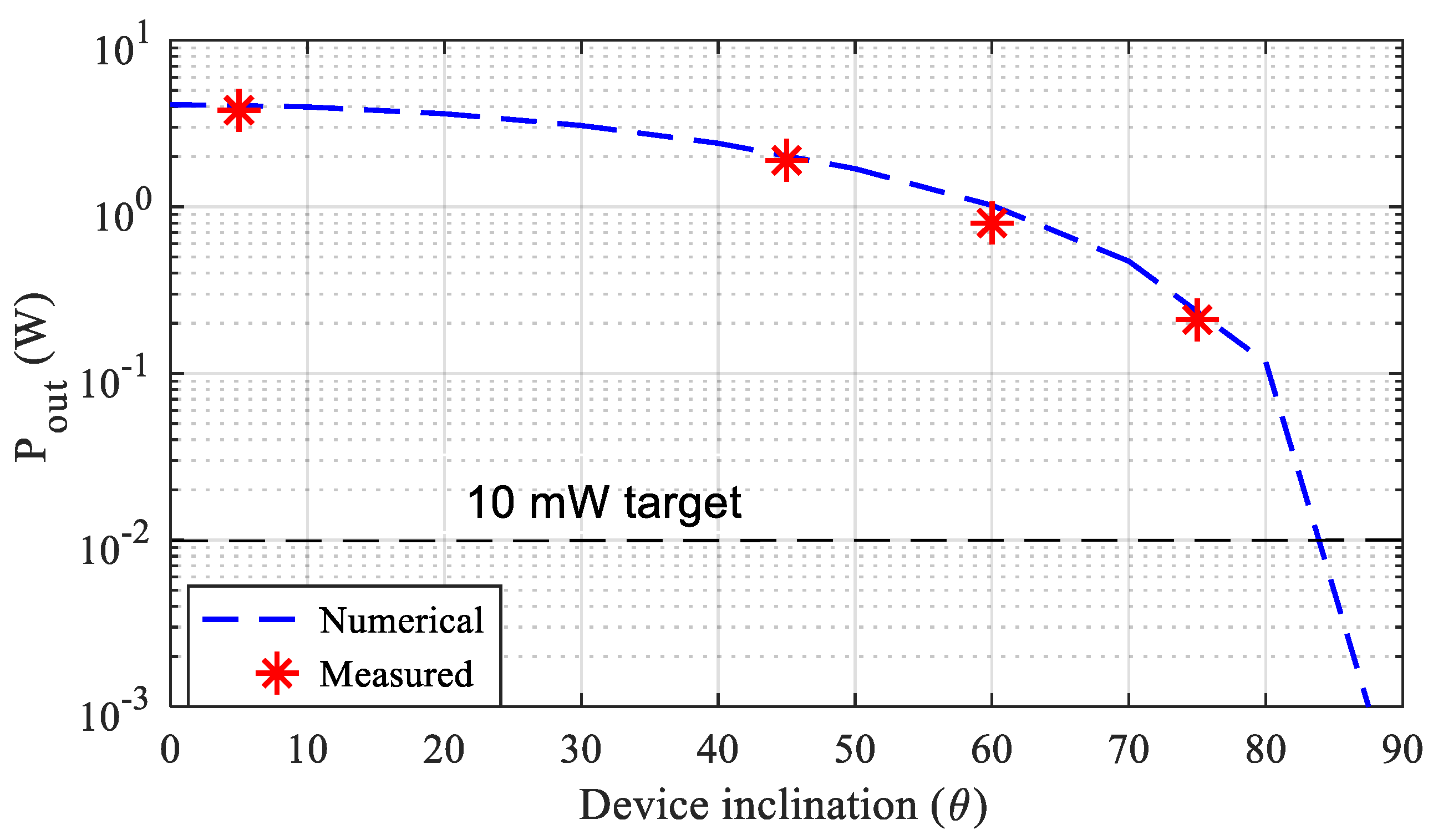
The output power is then measured as Pout = (Vout)2/RL, being Vout the load voltage. The amplitude of the input voltage Vin is manually adjusted in order to obtain an output power Pout = 10 mW. The measured and simulated electrical quantities (current I1 flowing into the primary coil and the efficiency η) are shown in Table 4, where a satisfactory agreement can be observed. The measured input current I1 and voltage Vin waveforms at the output of the inverter are shown in Figure 18 while the load voltage Vout is shown in Figure 19 for the test case #3. For the same test case, the tolerance of the WPT systems to misalignment conditions has been investigated. This aspect is very important as the implantation position of the device (mostly the angular alignment) can be variable. To this aim, the transferred power is measured and calculated while keeping fixed the primary current (I1 = 4 A, MMFmax = 23.7 At) for several angles θ of the pacemaker housing/secondary coil axis.The results are shown in Figure 20 confirming that the WPT system can transfer 10 mW target power up to an inclination angle θ = 85°. Finally, several measurements have been addressed to verify the capability of powering the device in a large volume inside the torso. To this aim, the device for the test case #3 was placed in many positions pn inside the torso (see Figure 8), and the electrical performances were numerically calculated and measured for a fixed output power Pout = 10 mW. The results obtained are shown in Table 5 highlighting the very good tolerance of the system to a variable position of the device inside the torso.
4. Conclusions
A feasibility study to power a deep implant with no fixed position using a WPT technology with a large size primary coil has been presented. The study has revealed that the optimal frequency to energize deep implants using resonant coupled magnetic coils at IFs is around 4 MHz. This value is obtained considering both the biological tissue attenuation and the compliance with the BRs specified by the EMF safety standards.
As regards the design of both transmitting and receiving coils, multiple primary coil configurations have first been analyzed in order to derive the best coverage area for the recharging process of a deep AIMD. Then, the design and optimization of the receiving coil for a leadless pacemaker has been proposed for the first time. Finally, three WPT demonstrators have been realized and tested to validate the proposed technology. The results have demonstrated that deep implants with titanium housing without ferrite cover can also be successfully powered and this is an important new result.
Author Contributions
T.C., S.C., V.D.S., F.M and M.F. conceived and planned the experiments. T.C. carried out the experiments. S.C., V.D.S., F.M and M.F. planned and carried out the simulations. All authors provided critical feedback, improved the final design, analyzed the data and wrote the paper.
Funding
This research received no external funding
Conflicts of Interest
The founding sponsors had no role in the design of the study; in the collection, analyses, or interpretation of data; in the writing of the manuscript, and in the decision to publish the results.
References
- Campi, T.; Cruciani, S.; Palandrani, F.; De Santis, V.; Hirata, A.; Feliziani, M. Wireless Power Transfer Charging System for AIMDs and Pacemakers. IEEE Trans. Microw. Theory Tech. 2016, 64, 633–642. [Google Scholar] [CrossRef]
- Campi, T.; Cruciani, S.; De Santis, V.; Feliziani, M. EMF Safety and Thermal Aspects in a Pacemaker Equipped with a Wireless Power Transfer System Working at Low Frequency. IEEE Trans. Microw. Theory Tech. 2016, 64, 375–382. [Google Scholar] [CrossRef]
- Xiao, C.; Wei, K.; Cheng, D.; Liu, Y. Wireless Charging System Considering Eddy Current in Cardiac Pacemaker Shell: Theoretical Modeling, Experiments, and Safety Simulations. IEEE Trans. Ind. Electron. 2017, 64, 3978–3988. [Google Scholar] [CrossRef]
- Monti, G.; Arcuti, P.; Tarricone, L. Resonant Inductive Link for Remote Powering of Pacemakers. IEEE Trans. Microw. Theory Tech. 2015, 63, 3814–3822. [Google Scholar] [CrossRef]
- Campi, T.; Cruciani, S.; De Santis, V.; Maradei, F.; Feliziani, M. Feasibility Study of a Wireless Power Transfer System Applied to a Leadless Pacemaker. In Proceedings of the IEEE Wireless Power Transfer Conference (WPTC), Montreal, Canada, 3–7 June 2018. [Google Scholar]
- Yang, C.-L.; Chang, C.-K.; Lee, S.-Y.; Chang, S.-J.; Chiou, L.-Y. Efficient Four-Coil Wireless Power Transfer for Deep Brain Stimulation. IEEE Trans. Microw. Theory Tech. 2017, 65, 2496–2507. [Google Scholar] [CrossRef]
- Puers, R.; Carta, R.; Thoné, J. Wireless power and data transmission strategies for next-generation capsule endoscopes. J. Micromech. Microeng. 2011, 21, 054008. [Google Scholar] [CrossRef]
- Basar, M.R.; Ahmad, M.Y.; Cho, J.; Ibrahim, F. An Improved Wearable Resonant Wireless Power Transfer System for Biomedical Capsule Endoscope. IEEE Trans. Ind. Electron. 2018, 65, 7772–7781. [Google Scholar] [CrossRef]
- Poon, A.S.Y.; O’Driscoll, S.; Meng, T.H. Optimal Frequency for Wireless Power Transmission Into Dispersive Tissue. IEEE Trans. Antennas Propag. 2010, 58, 1739–1750. [Google Scholar] [CrossRef]
- Ho, J.S.; Kim, S.; Poon, A.S.Y. Midfield Wireless Powering for Implantable Systems. Proc. IEEE 2013, 101, 1369–1378. [Google Scholar] [CrossRef]
- International Commission on Non-Ionizing Radiation Protection. Guidelines for limiting exposure to time-varying electric and magnetic fields for low frequencies (1 Hz–100 kHz). Health Phys. 2010, 99, 818–836. [Google Scholar]
- International Commission on Non-Ionizing Radiation Protection. Guidelines for limiting exposure to time-varying electric, magnetic, and electromagnetic fields (up to 300 GHz). Health Phys. 1998, 74, 494–522. [Google Scholar]
- IEEE.Std.C95.1-2005. IEEE standard for safety levels with respect to human exposure to radio frequency electromagnetic fields, 3 kHz to 300 GHz. 2006. Available online: http://0-dx-doi-org.brum.beds.ac.uk/10.1109/ieeestd.1999.89423 (accessed on 25 May 2019).
- Basar, M.R.; Yazed, A.M.; Cho, J.; Fatimah, I. A wireless power transmission system for robotic capsule endoscopy: Design and optimization. In Proceedings of the 2014 IEEE MTT-S International Microwave Workshop Series on RF and Wireless Technologies for Biomedical and Healthcare Applications (IMWS-Bio2014), London, UK, 8–10 December 2014. [Google Scholar]
- Hasgall, P.A.; Di Gennaro, F.; Baumgartner, C.; Neufeld, E.; Lloyd, B.; Gosselin, M.C.; Payne, D.; Klingenböck, A.; Kuster, N. IT’IS Database for thermal and electromagnetic parameters of biological tissues. Version 4.0. 15 May 2018. Available online: http://www.itis.swiss/database (accessed on 10 December 2018).
- Bronaugh, E.L. Helmholtz coils for calibration of probes and sensors: Limits of magnetic field accuracy and uniformity. In Proceedings of the IEEE International Symposium on Electromagnetic Compatibility, Atlanta, GA, USA, 14–18 August 1995. [Google Scholar]
- Chen, X.L.; Umenei, A.E.; Chavannes, N.; De Santis, V.; Mosig, J.; Kuster, N. Human Exposure to Close-Range Resonant Wireless Power Transfer Systems as a Function of Design Parameters. IEEE Tran. Electromagn. Compat. 2014, 56, 1027–1034. [Google Scholar] [CrossRef]
- De Santis, V.; Chen, X.L.; Laakso, I.; Hirata, A. An equivalent skin conductivity model for low-frequency magnetic field dosimetry. Biomed. Phys. Eng. Express 2015, 1, 015201. [Google Scholar] [CrossRef]
- Christ, A.; Kainz, W.; Hahn, E.G.; Honegger, K.; Zefferer, M.; Neufeld, E.; Rascher, W.; Janka, R.; Bautz, W.; Chen, J.; et al. The Virtual Family—Development of surface-based anatomical models of two adults and two children for dosimetric simulations. Phys. Med. Biol. 2010, 55, N23–N38. [Google Scholar] [CrossRef] [PubMed]
- Sim4Life-v3.2. SIMulation 4 LIFE Science Platform. Available online: http://www.zurichmedtech.com/sim4life (accessed on 10 November 2018).
- De Santis, V.; Chen, X.L. On the issues related to compliance assessment of ICNIRP 2010 basic restrictions. J. Radiol. Prot. 2014, 34, N31–N39. [Google Scholar] [CrossRef] [PubMed]
- ANSI/AAMI/ISO 14117:2012. Active Implantable Medical Devices—Electromagnetic Compatibility—Emc Test Protocols for Implantable Cardiac Pacemakers, Implantable Cardioverter Defibrillators and Cardiac Resynchronization Device. Available online: https://www.iso.org/obp/ui/#iso:std:iso:14117:ed-1:v1:en (accessed on 25 May 2019).
- Campi, T.; Cruciani, S.; Feliziani, M. Magnetic shielding of Wireless Power Transfer systems. In Proceedings of the International Symposium Electromagnetic Compatibility (EMC’14), Tokyo, Japan, 12–16 May 2014; pp. 422–425. [Google Scholar]
- Campi, T.; Cruciani, S.; Maradei, F.; Feliziani, M. Magnetic shielding design of Wireless Power Transfer systems. In Proceedings of the 2015 IEEE Applied Computational Electromagnetics (ACES), Williamsburg, VA, USA, 22–26 March 2015; pp. 1–2. [Google Scholar]
- Campi, T.; Cruciani, S.; Maradei, F.; Feliziani, M. Near-Field Reduction in a Wireless Power Transfer System Using LCC Compensation. IEEE Trans. Electromagn. Compat. 2017, 59, 686–694. [Google Scholar] [CrossRef]
- Kim, D.-H.; Kim, J.; Park, Y.-J. Optimization and Design of Small Circular Coils in a Magnetically Coupled Wireless Power Transfer System in the Megahertz Frequency. IEEE Trans. Microw. Theory Tech. 2016, 64, 2652–2663. [Google Scholar] [CrossRef]
- Abiri, P.; Abiri, A.; Sevag Packard, R.R.; Ding, Y.; Yousefi, A.; Ma, J.; Bersohn, M.; Nguyen, K.-L.; Markovic, D.; Moloudi, S.; et al. Inductively powered wireless pacing via a miniature pacemaker and remote stimulation control system. Sci. Rep. 2017, 7, 6180. [Google Scholar] [CrossRef] [PubMed]
- Das, R.; Yoo, H. Biotelemetry and Wireless Powering for Leadless Pacemaker Systems. IEEE Microw. Wirel. Compon. Lett. 2015, 25, 262–264. [Google Scholar] [CrossRef]
- Stogryn, A. Equations for Calculating the Dielectric Constant of Saline Water (Correspondence). IEEE Trans. Microw Theory Tech. 1971, 19, 733–736. [Google Scholar] [CrossRef]
Figure 1.
Sketch of the primary coil configuration made by 2 series-connected solenoids: (a) top-bottom, (b) front-back, (c) right-left.
Figure 1.
Sketch of the primary coil configuration made by 2 series-connected solenoids: (a) top-bottom, (b) front-back, (c) right-left.

Figure 2.
Sketch of the electro-geometrical configuration made of a 3D simplified multilayer torso with 2- solenoids (top-bottom) excitation.
Figure 2.
Sketch of the electro-geometrical configuration made of a 3D simplified multilayer torso with 2- solenoids (top-bottom) excitation.

Figure 3.
Scheme of the optimal frequency selection procedure.

Figure 4.
Maximum admissible magnetomotive force MMF vs. frequency.

Figure 5.
Maps of Vmax in a small loop (S = 1 cm2) inside the simplified model of a human torso at different frequencies.
Figure 5.
Maps of Vmax in a small loop (S = 1 cm2) inside the simplified model of a human torso at different frequencies.

Figure 6.
Maps of Vmax in a small loop (S = 1 cm2) inside the human body for different values of the separation distance ht between the solenoids: (a) ht = 50 mm; (b) ht = 100 mm; (c) ht = 150 mm.
Figure 6.
Maps of Vmax in a small loop (S = 1 cm2) inside the human body for different values of the separation distance ht between the solenoids: (a) ht = 50 mm; (b) ht = 100 mm; (c) ht = 150 mm.

Figure 7.
Duke human body model (HBM) with transmitting coil (a), magnetic flux density distribution in dB inside the torso normalized to 100 μT (b), maps of induced E-field (c) and SAR (d) inside Duke’s torso normalized to the peak values.
Figure 7.
Duke human body model (HBM) with transmitting coil (a), magnetic flux density distribution in dB inside the torso normalized to 100 μT (b), maps of induced E-field (c) and SAR (d) inside Duke’s torso normalized to the peak values.

Figure 8.
Sketch of a generic cylindrical active implantable medical device (AIMD) with a rotation θ between the excitation and the device coil axes.
Figure 8.
Sketch of a generic cylindrical active implantable medical device (AIMD) with a rotation θ between the excitation and the device coil axes.

Figure 9.
Magnetic flux lines and B maps in dBT for three housing materials for θ = 0° (silicone (a), titanium (b), titanium with ferrite cover (c)) and for θ = 60° (silicone (d), titanium (e), titanium with ferrite cover (f)).
Figure 9.
Magnetic flux lines and B maps in dBT for three housing materials for θ = 0° (silicone (a), titanium (b), titanium with ferrite cover (c)) and for θ = 60° (silicone (d), titanium (e), titanium with ferrite cover (f)).

Figure 10.
Equivalent circuits for series-series (SS) (a) and series-parallel (SP) (b) compensation topologies. Equivalent two-port network model (c).
Figure 10.
Equivalent circuits for series-series (SS) (a) and series-parallel (SP) (b) compensation topologies. Equivalent two-port network model (c).

Figure 11.
Secondary coil configuration.

Figure 12.
Efficiency η vs. N2 for SS and SP compensation topologies.

Figure 13.
Output power Pout vs. N2 for SS and SP compensation topologies.

Figure 14.
Efficiency η vs. load resistance RL for SP compensation topology.

Figure 15.
Output power Pout vs. inclination angle θ.

Figure 16.
SAR (a) and temperature increase (b) distribution inside the simplified torso model.

Figure 17.
Sketch of the measurement setup with details of the three devices.

Figure 18.
Measured waveforms of the input voltage Vin (red line) and input current I1 (light blue line).
Figure 18.
Measured waveforms of the input voltage Vin (red line) and input current I1 (light blue line).

Figure 19.
Measured output voltage Vout.

Figure 20.
Output power Pout vs. inclination angle θ.


Table 1.
Maximum avg. internal E and specific absorption rate (SAR) values for MMF = 23.7 At.
| Avg 2 × 2 × 2 mm3 E (V/m) | Avg 5 mm E (V/m) | 10 g avg SAR (W/kg) | |
|---|---|---|---|
| Calculated | 324 | 484 | 1.98 |
| BR Limit | 540 (ICNIRP) | 835 (IEEE) | 2.00 (ICNIRP-IEEE) |
Table 2.
Flux linkage ϕ in Wb vs angle inclination and materials.
| Angle θ | Silicone | Titanium | Titanium + Ferrite Cover |
|---|---|---|---|
| 0° | 3.62 × 10⁻¹⁰ | 1.15 × 10⁻¹⁰ | 2.69 × 10⁻⁹ |
| 30° | 3.16 × 10⁻¹⁰ | 1.01 × 10⁻¹⁰ | 2.34 × 10⁻⁹ |
| 60° | 1.90 × 10⁻¹⁰ | 6.54 × 10⁻¹⁰ | 1.36 × 10⁻⁹ |
| 80° | 0.76 × 10⁻¹⁰ | 0.33 × 10⁻¹⁰ | 0.48 × 10⁻⁹ |
Table 3.
Calculated and measured secondary circuit parameters.
| Test Case | L2 (μH) | M (nH) | R2 (mΩ) | |
|---|---|---|---|---|
| #1 | Numerical | 430 | 18 | 120 |
| Measured | 480 | 17 | 180 | |
| #2 | Numerical | 540 | 13 | 630 |
| Measured | 490 | 10 | 540 | |
| #3 | Numerical | 1420 | 84 | 840 |
| Measured | 1220 | 77 | 920 | |
Table 4.
Calculated and measured I1,RMS (A) and efficiency η.
| Test Case | Primary Coil Current (A) | Efficiency η | ||
|---|---|---|---|---|
| Numerical | Measured | Numerical | Measured | |
| #1 | 0.20 | 0.23 | 0.40 | 0.34 |
| #2 | 0.49 | 0.61 | 0.09 | 0.07 |
| #3 | 0.14 | 0.15 | 0.60 | 0.58 |
Table 5.
Measured efficiency and I1 (A) at variable device positions.
| dpx (mm) | dpz (mm) | Efficiency η | Primary Coil Current (A) |
|---|---|---|---|
| 0 | 0 | 0.47 | 0.25 |
| 50 | 0 | 0.51 | 0.20 |
| 100 | 0 | 0.52 | 0.18 |
| 0 | 50 | 0.55 | 0.20 |
| 50 | 50 | 0.58 | 0.16 |
| 100 | 50 | 0.58 | 0.15 |
© 2019 by the authors. Licensee MDPI, Basel, Switzerland. This article is an open access article distributed under the terms and conditions of the Creative Commons Attribution (CC BY) license (http://creativecommons.org/licenses/by/4.0/).
Share and Cite
MDPI and ACS Style
Campi, T.; Cruciani, S.; De Santis, V.; Maradei, F.; Feliziani, M. Near Field Wireless Powering of Deep Medical Implants. Energies 2019, 12, 2720. https://0-doi-org.brum.beds.ac.uk/10.3390/en12142720
AMA Style
Campi T, Cruciani S, De Santis V, Maradei F, Feliziani M. Near Field Wireless Powering of Deep Medical Implants. Energies. 2019; 12(14):2720. https://0-doi-org.brum.beds.ac.uk/10.3390/en12142720
Chicago/Turabian StyleCampi, Tommaso, Silvano Cruciani, Valerio De Santis, Francesca Maradei, and Mauro Feliziani. 2019. "Near Field Wireless Powering of Deep Medical Implants" Energies 12, no. 14: 2720. https://0-doi-org.brum.beds.ac.uk/10.3390/en12142720
Note that from the first issue of 2016, this journal uses article numbers instead of page numbers. See further details here.