Oscillations Analysis of Front-Mounted Beet Topper Machine for Biomass Harvesting
by
 , and
, and
Volodymyr Bulgakov
1, 
Simone Pascuzzi
2,* ,
,
Alexandros Sotirios Anifantis
2 and
Francesco Santoro
2
1
Department of Mechanics, Faculty of Construction and Design, National University of Life and Environmental Sciences of Ukraine, 03041 Kyiv, Ukraine
2
Department of Agricultural and Environmental Science, University of Bari Aldo Moro, Via Amendola, 165/A, 70126 Bari, Italy
*
Author to whom correspondence should be addressed.
Energies 2019, 12(14), 2774; https://0-doi-org.brum.beds.ac.uk/10.3390/en12142774
Submission received: 14 June 2019
/
Revised: 13 July 2019
/
Accepted: 17 July 2019
/
Published: 19 July 2019
(This article belongs to the Special Issue WP3 – Innovation in Agriculture and Forestry Sector for Energetic Sustainability)
Abstract
:The beet leaves and tops, which currently are excluded from the production process of sugar, could be an interesting opportunity for the production of renewable energy. Usually, the defoliators are joined with root collar remover machines, which are installed in front of the tractor. In working conditions on soils having natural roughness these front-mounted beet topper machines carried by tractors are affected by angular oscillations in a longitudinal-vertical plane that strongly affect the cutting uniformity. A theoretical study of these oscillations was carried out in this paper using Lagrange II kind equations, with the aim to assess the design and kinematic parameters of a front-mounted beet topper, corresponding to more stable and suitable movements in the longitudinal-vertical plane. A numerical simulation was then performed adopting the developed mathematical model. In order to improve the efficiency of this harvesting machine, a significant role is assumed by the soil preparation. In this work the stiffness and damping parameters of the feeler wheels pneumatic tires have been considered constant but further studies are in progress to assess their effective importance and influence for reducing the vibration of the front-mounted beet topper machine with the final aim to achieve a better machine design.
1. Introduction
Sugar beet is an extensive crop of great agronomic value with important production and economic results if properly managed [1]. The cultivation of sugar beet requires the knowledge of agronomic, nutritional, and physiological elements that characterize the soil-plant-atmosphere ecosystem [2]. In particular, the most important aspect to keep in mind is that from this plant the sugar is obtained, which is produced in the leaves (photosynthetic process) and accumulated in the root. The process of accumulation occurs obviously when the foliar apparatus reaches enough development to guarantee a production of sucrose higher than the daily consumption of the plant itself, considering that the solar radiation intercepted by the leaf surface affects the growth processes of the plant, and the production of dry matter [3,4].
The cultivation of sugar beet and the by-products deriving from their industrial processing represent also an important renewable energy resource within the agricultural sector [5]. As known, electricity can be produced from the biogas derived from the fermentation of the pulp, which is a by-product of sugar refineries [6]. Furthermore, agricultural residues represent another important biomass resource to be used as a substrate in anaerobic digestion for the production of renewable energy. The use of beet leaves and tops, currently excluded from the production process of sugar, could be an interesting incoming opportunity [7].
For all the above-mentioned reasons is a rather complicated and urgent task for beet-growing sector to develop a high-performance and high-quality harvesting of sugar beet tops [8,9].
Sugar-beet harvesting requires a set of specific operations: (i) defoliation; (ii) root collar remover; (iii) uprooting; (iv) cleaning. The defoliators usually are joined with root collar remover machines that can be installed in front of the tractor, thus allowing the use of a harvester machine mounted at the back of the tractor itself [10].
Experimental tests carried out with a front-mounted beet topper machine highlight that the cutting uniformity over the machine operative width as well as the full harvesting and transportation without loss, is strongly affected by machine oscillating movements which are, in turn, produced by soil roughness, tractor forward speed, location of feeler wheels related to machine suspension system, etc. In particular, the oscillations in the vertical plane of front-mounted beet topper machines could be related with pneumatic feeler wheels usage but, despite the widespread use of such kind of machines, there are no detailed analytical studies concerning these movements [11,12,13]. In this regard, a theoretical study of the oscillations of front-mounted beet topped machine was carried out using Lagrange II kind equations even if not all acting forces on the dynamic system were considered [14,15]. Conversely, a more accurate mathematical model should analyze also the effect of the design parameters of the above-mentioned machine, on the oscillatory movements along sugar beet roots rows due to soil roughness [16]. Taking in mind the aforesaid, the aim of this work is to assess the design and kinematic parameters of a front-mounted beet topper, corresponding to more stable and suitable movements in the longitudinal-vertical plane and reduction of the indicated oscillations. Therefore, a mathematical model of the movement of a front-mounted beet topper machine, mounted on a wheeled tractor, has been developed that describe oscillations of the corresponding rotary cutting apparatus in a longitudinally vertical plane when it moves on irregularity ground using pneumatic feeler-wheels.
2. Materials and Methods
2.1. The Developed and Built Front-Mounted Beet Topper Machine
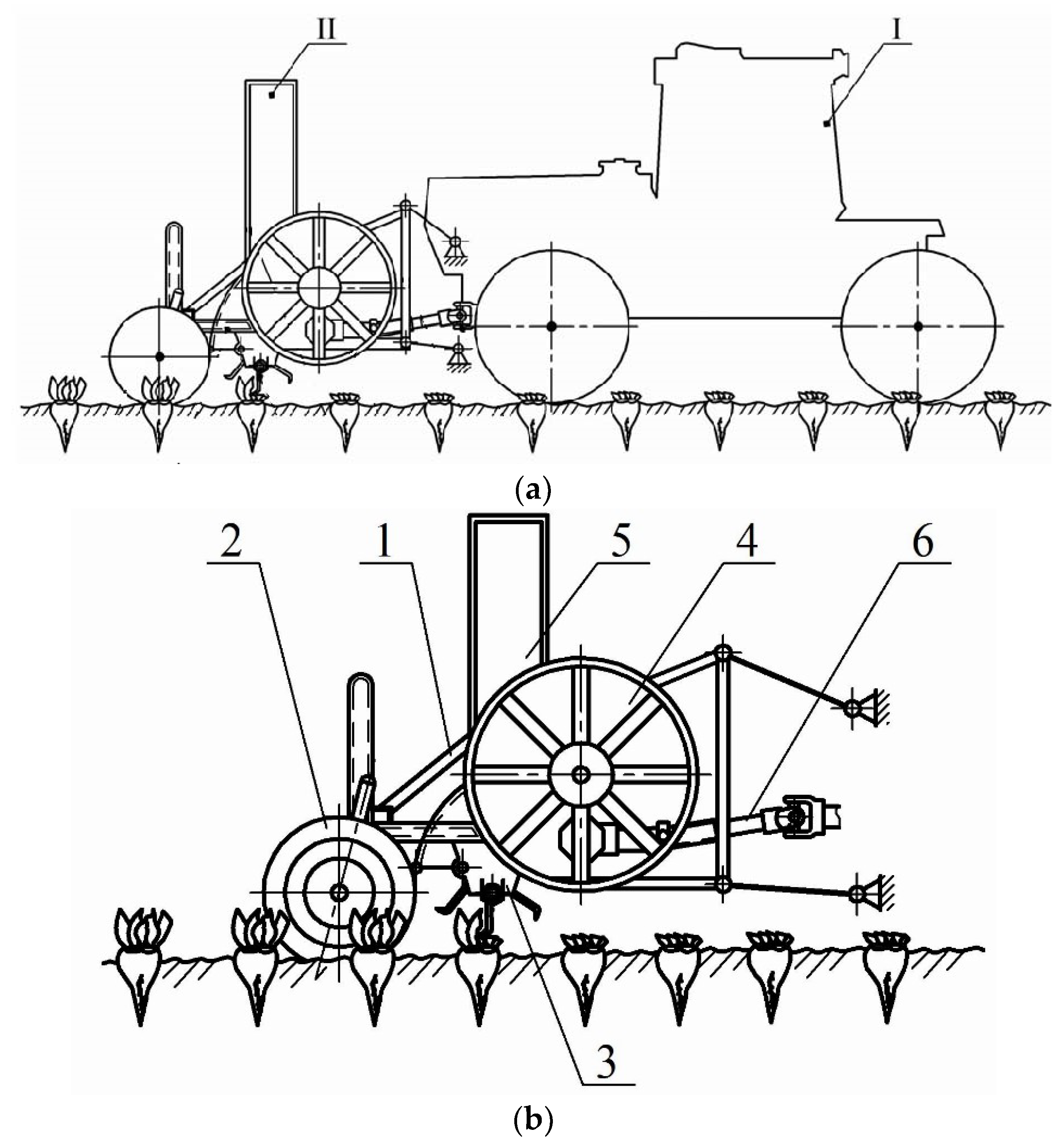
Based on the principle of a mower-shredder, a new universal front-mounted beet topper machine has been developed, which has been mounted on a wheeled tractor (Figure 1a). This rotary beet topper machine cuts in a continuous way both the rosette of the leaves and the weeds, transporting the cut material into a vehicle that follows sideways [8].
The machine performs its technological process as follows. During the machine movement in the forward direction, the feeler wheels (2 in Figure 1b) located in the front part of the movable frame (1 in Figure 1b), adjusts the rotor (3 in Figure 1b) putting the knives at the required cutting height. The knives themselves are arc-shaped, hinged mounted on a cylindrical surface along the length of the rotor (3 in Figure 1b) assures an effective cut of the top of the beets [9,10,11]. Knives have high absolute speed (from 20–25 m s−1 to 40–50 m s−1 for thicker-stemmed crops), ensuring the effective cut of the entire array of tops [14].
The beet tops already cut by the knives move upper-ward inside the case and then they fall onto the screw conveyor so they can be moved to the rear part of the machine where the loading mechanism (4 in Figure 1b), through the chute (5 in Figure 1b), discharges them into a sideway running vehicle. The front-mounted beet topper machine receives motion and power through a cardan universal joint (6 in Figure 1b) connected to the aggregating tractor front power take-off. The final part of the beet tops harvesting is completed by a rear mounted machine that cut the beet roots collar.
From the mechanisms described above, it is shown that the quantity of harvested beet tops and their qualitative characteristics using such beet top harvesting machine, are strictly affected by: (i) the stability of the movement of the rotary beet harvesting device in the longitudinal-vertical plane; (ii) the efficiency in following soil surface roughness over all the working width; (iii) overall design parameters, above all, those concerning the tractor-machine interface frame.
2.2. Theoretical Study of the Oscillations of the Front-Mounted Beet Topper Machine
A mathematical model of the rotary beet harvesting device was set up in order to evaluate its oscillation amplitude in the longitudinal-vertical plane, which depends on soil roughness and, in turn, is affected by the structural and kinematic parameters of the front-mounted beet topper machine itself [17].
An equivalent scheme of movement only in the longitudinal-vertical plane of the front-mounted beet topper machine has been initially set up (Figure 2) [8]. In the equivalent scheme two different conditions have been considered: (i) the feeler wheel is reaching the top of soil irregularity; (ii) the feeler wheel is on the top of this irregularity.
As represented in Figure 2, the front-mounted beet topper machine is connected to the tractor by means of a frame based on three beams (two lower— and one upper—), having hinges in the points , , , and . The radii of the feeler wheels and the beet top cutting device are respectively and .
is the mass of the front-mounted beet topper machine and the related weight is considered to be applied in the center of mass of the machine itself; is the mass of the two feeler wheels, which is supposed to be concentrated in point .
A dynamic system to the fixed cartesian coordinates is considered in such a way in which the plane is the longitudinal plane of the front-mounted beet topper machine and it is vertical and perpendicular to the soil surface.
Pneumatic feeler wheels are considered as elastic-damping models having a total stiffness coefficient and total damping coefficient .
It has been considered that both feeler wheels move almost in the same conditions when moving between the rows of sugar beet crops and it is possible to assume that while moving and crushing the upper and most loose soil layer they are in contact in point with the soil surface. At the same time, the profile representing the soil roughness can be represented as a harmonic function like the following [1,2]:
where, referring to Figure 2:
- [m]: Soil surface height irregularity;
- [m]: Half of the maximum soil roughness;
- [m]: Horizontal distance between two consecutives soil points having the same characteristics;
- [m]: Is the current coordinate with [m s−1] forward speed of the front-mounted beet topper machine.
In the mechanical behavior of the front-mounted beet topper machine jointed with the carrying tractor, it needs to be considered that during their common forward movement, the vertical oscillations of the tractor center of mass, even if not completely cancelled, are significantly smoothed due to its high inertia and the flatting effect produced on the soil by the big tractor weight.
Therefore, the hinges located at the points and (Figure 2), as belonging to the tractor, also perform vertical oscillations, even if reduced in amplitude. Furthermore, these weak oscillations can be considered to not affect the oscillation of the front-mounted beet topper machine (hinged at the points due its considerable mass, so it can be assumed that the suspension points of the front-mounted beet topper machine move in a first approximation on a straight line.
The front-mounted beet topper machine, due to the soil roughness received through the feeler wheels, only has angular oscillations in the vertical plane around the point by an angle of rotation affected by the value of soil roughness in accordance to where the point of the feeler wheels, time by time, touch the soil surface.
The rotation of the frame of the machine around point are due to the torque of all the forces whose action line do not pass through the point that are:
- (a)
- the normal soil reactions applied at point of contact between the feeler wheels and the soil;
- (b)
- the tangential soil reactions applied at point of contact between the feeler wheels and the soil (where is the rolling friction coefficient related to the relative movement between the feeler wheels and the soil surface);
- (c)
- the weight of the front-mounted beet topper machine applied in its center of gravity;
- (d)
- the cutting resistance reaction of beet tops applied at point ;
- (e)
- the traction tension in the upper beam of the mounting frame between the front-mounted beet topper machine and the tractor in the direction from point to point .
Furthermore, along the lower traction of the mounting frame should be considered the tractor traction force , directed from point to point , but it does not contribute to moments around point
Finally, the elastic damping properties of the feeler wheels pneumatic tires also play a significant role in the vertical oscillation of the front-mounted beet topper machine. In this regard it is necessary to assess the potential energy
and dissipative function of this dynamic system to consider the elastic viscosity properties of the tires.
3. Results and Discussion
3.1. Mathematical Model
The use of Lagrange equations of the second kind are suitable to describe the motion of the front-mounted beet topper machine, which incorporate the constraints directly by judicious choice of generalized coordinates that; therefore, have to be defined [9].
The position of the frame of the front-mounted beet topper machine, including its center of mass (point in Figure 2), in the longitudinal-vertical plane is completely determined by the independent coordinate (Figure 2) of rotation of the frame of the machine which is, in turn, affected by the irregularity of the soil surface and by the feeler wheels elastic-damping properties.
Considering that the feeler wheels axis is rigidly connected to the main supporting frame, the vertical displacement [m] of their center of mass (point in Figure 2) can be defined as follows:
where, referring to Figure 2, [m] is distance (the length of the frame of the machine).
This dynamic system in the longitudinal-vertical plane has only one degree of freedom having one generalized coordinate and, so, the Lagrange equations of the second kind is [18,19,20]:
where:
- : kinetic energy;
- : generalized force;
- : potential energy;
- : dissipative function (Rayleigh function);
- : generalized coordinate;
- : generalized speed.
After a series of transformation (Appendix A), from Equation (3) is possible to obtain the nonlinear differential Equation (4), which models the angular oscillations of the frame of the front-mounted beet topper machine in the longitudinal-vertical plane.
In Equation (4), as well as constructive parameters (, , , , , , , , ), appear the modulus of two forces: The modulus of the cutting resistance reaction of beet tops applied at point and the modulus of the normal soil reactions applied at point of contact between the feeler wheels and the soil.
Experimentally evaluating the modulus of the cutting resistance reaction of beet tops (), the modulus of the normal soil reaction between the feeler wheels and the soil is given by (Appendix B):
With the initial condition at is possible to solve Equation (4) using the Runge-Kutta method in order to obtain and then the time dependent vertical movement of both the knife belonging to beet top cutting device (point E, Figure 2) and the center of mass (point C, Figure 2) of the whole machine using, respectively, the following equations:
where:
- : horizontal distance between the front-mounted beet topper machine rotation axis and cutting device rotation axis;
- : horizontal distance between the front-mounted beet topper machine rotation axis and its center of mass.
3.2. Numerical Simulation
The developed mathematical model has been adopted as a base for numerical simulations using the parameters reported in the following Table 1.
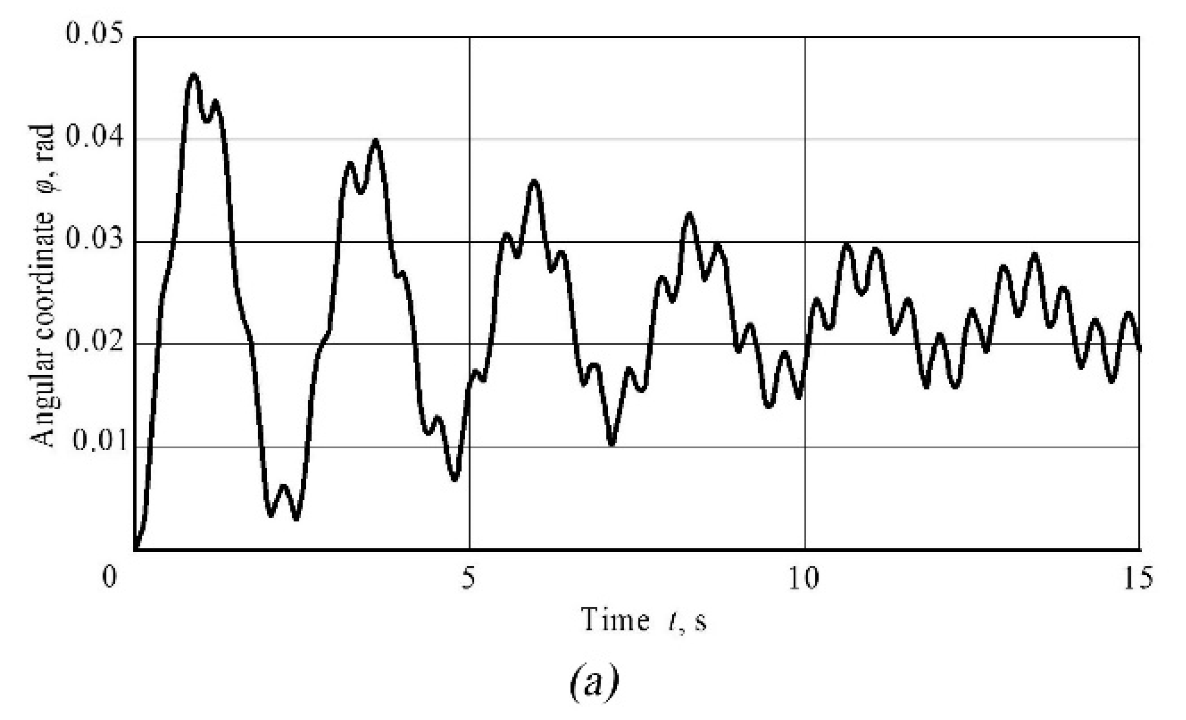
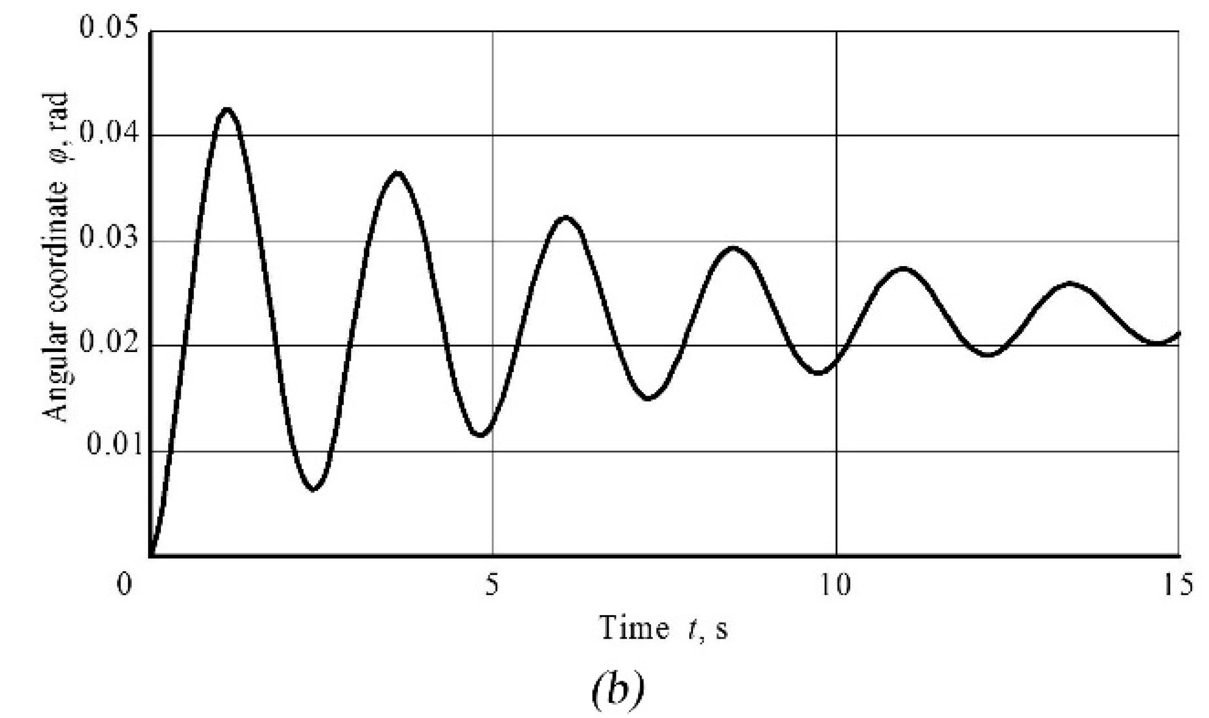
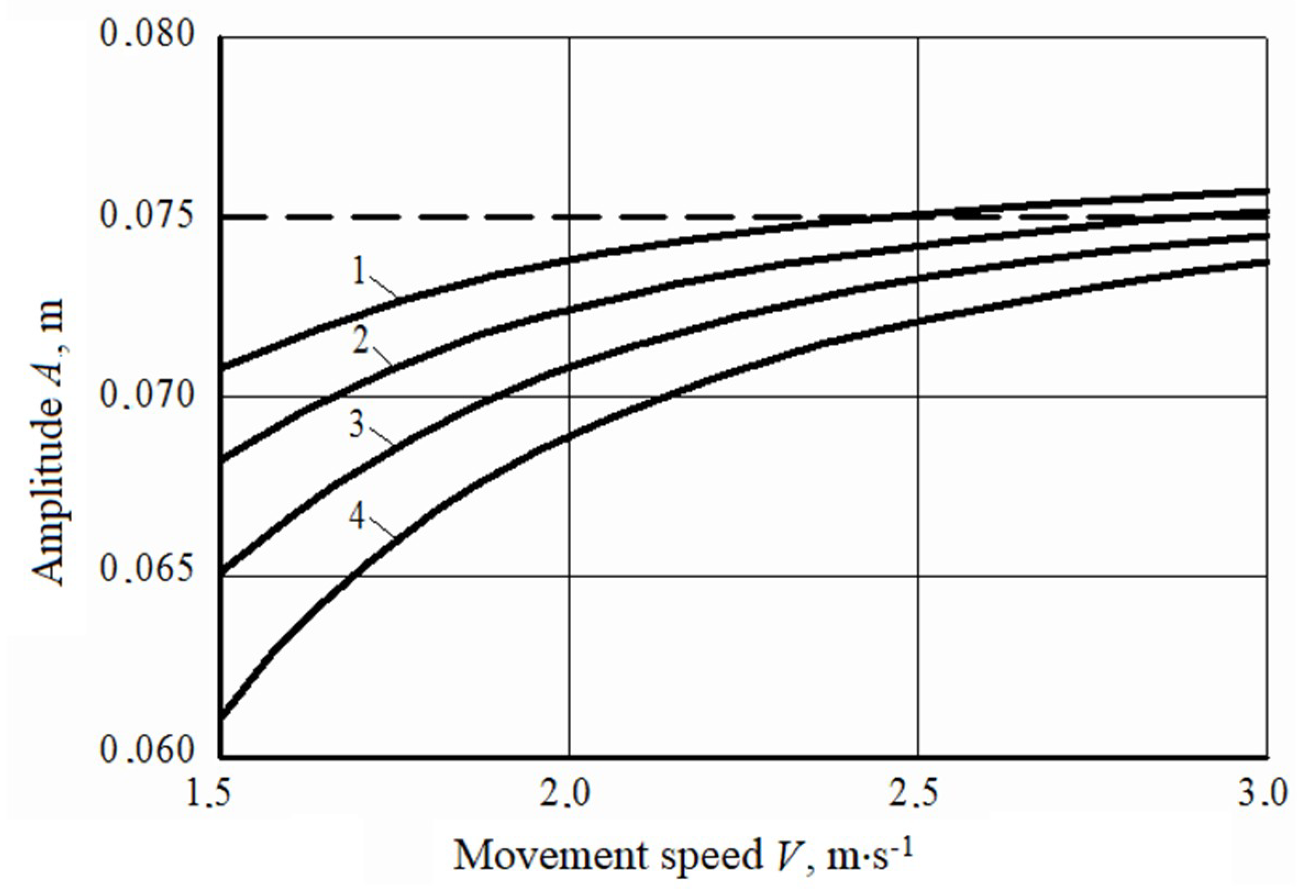
Several numerical simulations of the oscillation behavior of the front-mounted beet topper machine have been carried out, considering the agrotechnical requirements concerning the restriction of forward velocity of a front-mounted beet topper machine, which should be in the range 1.5 ≤ V ≤ 3.0 [7] and the results are reported in the following Figure 3, Figure 4 and Figure 5.
In particular in Figure 3a,b are reported, for two different tractor velocities (1.5 m s−1 and 3.0 m s−1, respectively), the angular oscillation trend of the front-mounted beet topper machine center of mass at the beginning of its movement in the case of a distance of between two consecutive soil irregularities (l1) equal to 0.7 m (Table 1). In both cases a damped behavior is shown with the main difference that at a low value of forward speed the corresponding trend curve has a jagged appearance as the feeler wheels have enough time to follow all the soil irregularities, while at higher forward speed the trend curve has a smoother shape as the feeler wheels have both not enough time to follow all the soil irregularities and these are crushed by the feeler wheels themselves. Furthermore, in both cases, the angular oscillation extends asymptotically to a common value equal to ϕ = 0.02 rad which, in turn, strictly depends upon the stiffness and damping coefficients of the feeler wheels 2C and 2μ, respectively (Table 1).
The improvement of soil preparation, aimed at reducing its roughness, significantly reduces the amplitude of oscillations of the cutting device of front-mounted beet topper machine as shown in Figure 4.
In Figure 5 it is also shown that, regardless of soil roughness step, increasing the forward velocity within the considered range, the amplitude of oscillation increases and extends asymptotically to a common value close to A = 0.075 m. Furthermore, a better soil preparation (Line 4—Figure 4) produces a variation equal to 19.7% of the amplitude of oscillation while a worst soil preparation (Line 1—Figure 4) produces a variation equal to 7.0% increasing the velocity from 1.5 to 3.0 m s−1.
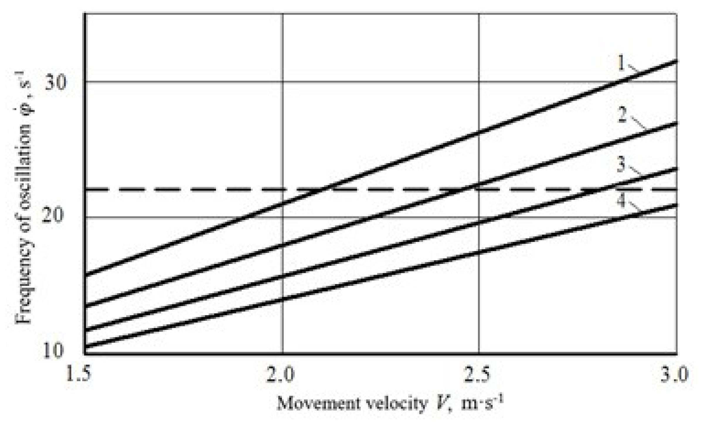
The frequency of forced oscillations of the cutting device of front-mounted beet topper machine have a linear trend in the entire range of forward velocity acceptable by an agrotechnical point of view, as shown in Figure 5, with an average percentual increase close to 100% for each of the considered soil roughness step. Furthermore, in case of better soil preparation, corresponding to step of irregularities equal to 0.9 m, it is less than 22 s−1 (Figure 5).
The numerical simulation shows that the developed mathematical model can be further used to study the influence of different constructive and kinematic parameters of the front-mounted beet topper machine in order be optimized with the final aim to assess and reduce the oscillations arising during its operation.
4. Conclusions
1. In working conditions on soils having natural roughness, front-mounted beet topper machine carried by a suitable tractor is affected by angular oscillations in a longitudinal-vertical plane that can be considered kinematic disturbances.
2. A motion equivalent scheme in a longitudinal-vertical plane has been developed and used, which considered all the external forces, all the dimensional and constructive parameters, and the soil roughness characteristics of soil roughness in the form of a harmonic function. The front-mounted beet topper machine frame rotation was used as a generalized coordinate in the Lagrange II kind nonlinear differential equation adopted as the mathematical model of the machine motion.
3. The numerical simulation of the oscillation characteristics in a longitudinal-vertical plane of the front-mounted beet topper machine has shown that, with the used constructive parameters, this oscillatory system is able to damp disturbing influences arising from soil roughness.
4. In order to improve the efficiency of this kind of machine, a significant role is assumed by the soil preparation, which should be carried out in order to flatten as much as possible the soil itself. As shown in the carried out numerical simulation, an increase in soil preparation leads to a reduction of the amplitude of oscillation close to 14.1% and the frequency oscillation close to 50% at the lowest forward velocity (1.5 m s−1). Furthermore, low forward velocities allow to reduce all oscillatory effects considering that, in the carried out numerical simulation, the amplitude and the frequency of oscillation are the lowest and, respectively equal to 0.061 m and 11.3 s−1 in the case of better soil preparation. It has to be considered, furthermore, that both soil preparation and forward velocity have to be balanced, considering the productivity aspect of the harvesting process as, in general cases, it is carried out by third-part companies that are required to optimize time efforts.
5. In this work the stiffness and damping parameters of the feeler wheels pneumatic tires have been considered to be constant. Further studies are in progress in which different values of these dynamic parameters will be considered variable in order to assess their effective importance and influence for reducing the vibration of the front-mounted beet topper machine with the final aim to achieve a better machine design.
Author Contributions
Conceptualization, V.B. and S.P.; methodology, V.B., S.P. and F.S.; software, validation, formal analysis and data curation, V.B., F.S. and A.S.A.; writing—original draft preparation, V.B., F.S., S.P.; writing—review and editing, F.S., S.P.; supervision, V.B. and S.P.
Funding
This research received no external funding.
Acknowledgments
Italian Authors wish to thank Giulia De Candia (Bari, Italy) for her help in translating and understanding Russian language references.
Conflicts of Interest
The authors declare no conflict of interest.
Appendix A
- : kinetic energy;
- : generalized force;
- : potential energy;
- : dissipative function (Rayleigh function);
- : generalized coordinate;
- : generalized speed.
The total kinetic energy T is, so, given by:
where:
- : kinetic energy of the translational motion;
- : kinetic energy of the rotational motion of machine frame around a point O;
- : kinetic energy of the vertical oscillations of the feeler wheels;
- : kinetic energy of rotational motion feeler wheels around their axes.
In particular:
where:
- [kg]: mass of the front-mounted beet topper machine;
- [m s−1]: forward speed of the center of mass of the machine;
- [kg m2]: moment of inertia of the frame the front-mounted beet topper machine relative to the axis (perpendicular to the longitudinal-vertical plane and passing through the point );
- [s−1]: angular speed of the frame of the machine;
- [kg]: mass of the feeler wheels;
- [m s−1]: speed of vertical oscillations of the feeler wheels;
- [s−1]: angular speed of the rotation of the frame of the machine;
- [kg m2]: moment of inertia of the two feelers wheels relative to their axis of rotation;
- [s−1]: angular speed of the feeler wheels.
It is possible to evaluate the angular speed of the feeler wheels by mean of the length of the circular arc using the following:
where:
- [m]: radius of the feeler wheels.
Considering that the feeler wheels move along the soil roughness profile defined by (1)
Substituting (A8) in (A7):
and, so:
Considering Equations (A3)–(A5), and (A10) and substituting them into (A2):
The potential energy P of the dynamic system is equal to the work of the elastic deformation forces of the pneumatic tires of both feeler wheels and is given by the following expression:
where:
- [N m−1]: stiffness coefficient of the pneumatic tires of the feeler wheels;
- [m]: distance between the axis of suspension of the front-mounted beet topper machine (point ) and the axis of the feeler wheels (point ).
The dissipative function R of the dynamic system is due to the viscous resistance forces of the pneumatic tires of both feeler wheels which are proportional to speed:
where:
- [N s m−1]: damping coefficient of the pneumatic tires of the feeler wheels;
- [m]: distance between the axis of suspension of the front-mounted beet topper machine (point ) and the axis of the feeler wheels (point ).
In order to evaluate the last remaining term to be used in the (A1), let us consider the elementary work of all active forces related to an infinitesimal rotation :
where:
- [N]: modulus of normal soil reactions of feeler wheels with the soil;
- [m]: arm of ;
- [N]: modulus of tangential soil reactions of feeler wheels with the soil;
- [m]: arm of ;
- [N]: modulus of cutting resistance reaction of beet tops;
- [m]: arm of ;
- [N]: modulus of weight of the front-mounted beet topper machine;
- [m]: arm of ;
- [N]: modulus of traction tension in the upper connection beam ;
- [m]: arm of ;
The generalized force acting on the dynamic system is, thus, the algebraic sum of the moments of all active forces relative to point :
- Calling the slope of the tangent to the profile representing the soil roughness: ;
- calling the angle between the vertical part of the front-mounted beet topper machine frame and the normal to the upper connection beam
- remembering that [m] is the length of the frame of the machine;
- remembering that [m] is the height of the frame of the machine;
- remembering that = [m] is the radius of the beet top cutting device in (A13), considering Figure 2;
- ;
- ;
and, so, Equation (A15) can be written as:
Is it now possible, using (A11), (A12) and (A15) to write four of the five terms that appear in (A1).
Finally, using (A17), (A18), (A16), (A19), and (A20) it is possible to write the final expression of (A1):
that can be written in the following form:
Appendix B
The modulus of the normal reaction between the feeler wheels and the soil can be determined from the equilibrium condition of the system at a fixed time, setting equal to zero the algebraic sum of the moments of all forces acting on the system relative to point .
The above-mentioned condition is raised, when (A16):
As the angles and in (A23) are time-dependent, it is convenient to fix the time at which the point of contact between the feeler wheels and the profile of soil roughness is in the upper most part of the profile itself: In this case (Figure 2) so (A23) simplifies in:
and, finally:
References
- Bulgakov, V.M. Beet Harvesting Machines; Agrarian Science: Kiev, Ukraine, 2011; 351p. [Google Scholar]
- Khvostov, V.A.; Reingart, E.S. Machines for Harvesting Root Crops and Onions (Theory, Design, Calculation); VISHOM: Moscow, Russia, 1995; 391p. [Google Scholar]
- Cerruto, E.; Manetto, G.; Santoro, F.; Pascuzzi, S. Operator Dermal Exposure to Pesticides in Tomato and Strawberry Greenhouses from Hand-Held Sprayers. Sustainability 2018, 10, 2273. [Google Scholar] [CrossRef]
- Pascuzzi, S.; Cerruto, E.; Manetto, G. Foliar spray deposition in a “tendone” vineyard as affected by airflow rate, volume rate and vegetative development. Crop Prot. 2017, 91, 34–48. [Google Scholar] [CrossRef]
- Manetto, G.; Cerruto, E.; Pascuzzi, S.; Santoro, F. Improvements in citrus packing lines to reduce the mechanical damage to fruit. Chem. Eng. Trans. 2017, 58, 391–396. [Google Scholar]
- Pascuzzi, S.; Cerruto, E. An innovative pneumatic electrostatic sprayer useful for tendone vineyards. J. Agric. Eng. 2015, XLVI:458, 123–127. [Google Scholar] [CrossRef]
- Bulgakov, V.; Adamchuk, V.; Ivanovs, S.; Ihnatiev, Y. Theoretical investigation of aggregation of top removal machine frontally mounted on wheeled tractor. Eng. Rural Dev. Jelgava 2017, 16, 273–280. [Google Scholar]
- Bulgakov, V.; Adamchuk, V.; Nozdrovický, L.; Ihnatiev, Y. Theory of Vibrations of Sugar Beet Leaf Harvester Front-Mounted on Universal Tractor. In Acta Technologica Agriculturae; Slovaca Universitas Agriculturae Nitriae: Nitra, Slovakia, 2017; Volume 20, pp. 96–103. [Google Scholar]
- Vasilenko, P.M. Introduction to Agricultural Mechanics; Agriculture: Kiev, Ukraine, 1996; 252p. [Google Scholar]
- Vasilenko, I.F. Theory of Cutting Machines Reaping Machines; Works of the VISHOM: Moscow, Russia, 1937; Volume 5, pp. 7–14. [Google Scholar]
- Reznik, N.E. The Theory of Cutting with a Blade and the Basics of Calculating the Cutting Apparatus; Mechanical Engineering: Moscow, Russia, 1975; 311p. [Google Scholar]
- Bosoy, E.S. Cutting Apparatus of the Harvesting Machines. Theory and Calculation; Mechanical Engineering: Moscow, Russia, 1967; 167p. [Google Scholar]
- Tatyanko, N.V. The calculation of the working bodies for cutting machines of sugar beet tops. Tract. Agric. Mach. 1962, 11, 18–21. [Google Scholar]
- Kolychev, E.I. On the choice of the design impact case in the study of the smoothness of the movement of tractors and agricultural machinery. Tract. Agric. Mach. 1976, 3, 9–11. [Google Scholar]
- Anifantis, A.S.; Pascuzzi, S.; Scarascia Mugnozza, G. Geothermal source heat pump performance for a greenhouse heating system. An experimental study. J. Agric. Eng. 2016, 47, 167–173. [Google Scholar] [CrossRef]
- Bulgakov, V.; Pascuzzi, S.; Nadykto, V.; Ivanovs, S. A mathematical model of the plane-parallel movement of an asymmetric machine-and-tractor aggregate. Agriculture 2018, 8, 151. [Google Scholar] [CrossRef]
- Bulgakov, V.; Pascuzzi, S.; Santoro, F.; Anifantis, A.S. Mathematical Model of the Plane-Parallel Movement of the Self-Propelled Root-Harvesting Machine. Sustainability 2018, 10, 3614. [Google Scholar] [CrossRef]
- Tucki, K.; Mruk, R.; Orynycz, O.; Gola, A. The Effects of Pressure and Temperature on the Process of Auto-Ignition and Combustion of Rape Oil and Its Mixtures. Sustinability 2019, 11, 3451. [Google Scholar] [CrossRef]
- Bulgakov, V.; Pascuzzi, S.; Ivanovs, S.; Kaletnik, G.; Yanovich, V. Angular oscillation model to predict the performance of a vibratory ball mill for the fine grinding of grain. Biosyst. Eng. 2018, 171, 155–164. [Google Scholar] [CrossRef]
- Anifantis, A.S.; Colantoni, A.; Pascuzzi, S.; Santoro, F. Photovoltaic and Hydrogen Plant Integrated with a Gas Heat Pump for Greenhouse Heating: A Mathematical Study. Sustainability 2018, 10, 378. [Google Scholar] [CrossRef]
Figure 1.
Front-mounted beet topper machine: (a) general view: I—carrying tractor; II beet topper machine; (b) constructive-technological scheme: 1—frame; 2—pneumatic feeler wheel; 3—rotary beet top cutting device; 4—loading mechanism of cutting beet top; 5—discharge chute; 6—drive working bodies.
Figure 1.
Front-mounted beet topper machine: (a) general view: I—carrying tractor; II beet topper machine; (b) constructive-technological scheme: 1—frame; 2—pneumatic feeler wheel; 3—rotary beet top cutting device; 4—loading mechanism of cutting beet top; 5—discharge chute; 6—drive working bodies.

Figure 2.
Equivalent scheme of the front-mounted beet topper machine.

Figure 3.
Angular oscillation of the front-mounted beet topper machine in the first period of its motion for a forward speed of 1.5 (a) and 3.0 m s−1 (b).
Figure 3.
Angular oscillation of the front-mounted beet topper machine in the first period of its motion for a forward speed of 1.5 (a) and 3.0 m s−1 (b).


Figure 4.
Relation between the amplitude of oscillations of the cutting device of the front-mounted beet topper machine A and the forward velocity V for different soil roughness step (1: 0.6 m; 2: 0.7 m; 3: 0.8 m; 4: 0.9 m).
Figure 4.
Relation between the amplitude of oscillations of the cutting device of the front-mounted beet topper machine A and the forward velocity V for different soil roughness step (1: 0.6 m; 2: 0.7 m; 3: 0.8 m; 4: 0.9 m).

Figure 5.
Relation between the frequency of oscillations of the cutting device of the front-mounted beet topper machine and the forward velocity V for different soil roughness step (1: 0.6 m; 2: 0.7 m; 3: 0.8 m; 4: 0.9 m).
Figure 5.
Relation between the frequency of oscillations of the cutting device of the front-mounted beet topper machine and the forward velocity V for different soil roughness step (1: 0.6 m; 2: 0.7 m; 3: 0.8 m; 4: 0.9 m).


Table 1.
Numerical simulations parameters.
| Parameter | Symbol | Unit | Value |
|---|---|---|---|
| Machine weight | N | 9480.0 | |
| Feeler wheels weight | N | 48.9 | |
| Machine moment of inertia relative to its rotation axis | Kg m2 | 60.0 | |
| Machine rotation axis-feeler wheels axis distance Machine frame length | m | 1.800 | |
| Machine frame height | OD | m | 0.580 |
| Angle between the vertical frame beam and the perpendicular to the upper suspension beam | rad | 0.087 | |
| Machine rotation axis-cutting device axis horizontal distance | m | 1.100 | |
| Machine rotation axis-center of mass horizontal distance | m | 0.800 | |
| Forward speed of the tractor | V | m s−1 | 1.5–3.0 |
| Cutting device radius | m | 0.365 | |
| Feeler wheels radius | m | 0.300 | |
| Feeler wheels pneumatic tires stiffness coefficient | N m−1 | 4000 | |
| Feeler wheels pneumatic tires damping coefficient | N s m−1 | 150 | |
| Half of the maximum soil roughness | m | 0.040 | |
| Horizontal distance between two consecutives soil irregularities | m | 0.700 | |
| Soil-feeler wheels friction coefficient | - | 0.30 | |
| Cutting resistance reaction of three beet tops | N | 300 | |
| Normal reaction component between feeler wheels and soil | N | 4117 | |
| Tangential reaction component between feeler wheels and soil | N | 1235 | |
| Traction tension in the upper beam of the mounting frame | N | 209 | |
| Traction tension in the lower beam of the mounting frame | N | 1750 |
© 2019 by the authors. Licensee MDPI, Basel, Switzerland. This article is an open access article distributed under the terms and conditions of the Creative Commons Attribution (CC BY) license (http://creativecommons.org/licenses/by/4.0/).
Share and Cite
MDPI and ACS Style
Bulgakov, V.; Pascuzzi, S.; Anifantis, A.S.; Santoro, F. Oscillations Analysis of Front-Mounted Beet Topper Machine for Biomass Harvesting. Energies 2019, 12, 2774. https://0-doi-org.brum.beds.ac.uk/10.3390/en12142774
AMA Style
Bulgakov V, Pascuzzi S, Anifantis AS, Santoro F. Oscillations Analysis of Front-Mounted Beet Topper Machine for Biomass Harvesting. Energies. 2019; 12(14):2774. https://0-doi-org.brum.beds.ac.uk/10.3390/en12142774
Chicago/Turabian StyleBulgakov, Volodymyr, Simone Pascuzzi, Alexandros Sotirios Anifantis, and Francesco Santoro. 2019. "Oscillations Analysis of Front-Mounted Beet Topper Machine for Biomass Harvesting" Energies 12, no. 14: 2774. https://0-doi-org.brum.beds.ac.uk/10.3390/en12142774
Note that from the first issue of 2016, this journal uses article numbers instead of page numbers. See further details here.