Article

On the Conflict between LVRT and Line Protection in LV Distribution Systems with PVs: A Current-Limitation-Based Solution

by
Aristotelis Tsimtsios
1,
Dionisis Voglitsis
2,
Ioannis Perpinias
3,
Christos Korkas
1 and
Nick Papanikolaou
1,*
1
Department of Electrical and Computer Engineering, Democritus University of Thrace, 67132 Xanthi, Greece
2
EMEA Solutions Engineering Center, On Semiconductor, 85609 Munich, Germany
3
Regulatory Authority for Energy, Pireos 132, 11854 Athens, Greece
*
Author to whom correspondence should be addressed.
Submission received: 6 June 2019 / Revised: 25 July 2019 / Accepted: 26 July 2019 / Published: 29 July 2019
(This article belongs to the Special Issue Power Electronics for Energy Saving)

Abstract

:
The upcoming adoption of low-voltage-ride-through requirements in low-voltage distribution systems is expected to raise significant challenges in the operation of grid-tied inverters. Typically, these inverters interconnect photovoltaic units, which are the predominant distributed energy resource in low-voltage distribution networks, under an umbrella of standards and protection schemes. As such, a challenging issue that should be considered in low-voltage distribution network applications, regards the coordination between the line protection scheme (typically consisting of a non-settable fuse) and the low-voltage-ride-through operation of photovoltaic generators. During a fault, the fuse protecting a low-voltage feeder may melt, letting the generator to continue its ride-through operation. Considering that the efficacy/speed of the anti-islanding detection is affected by ride-through requirements, this situation can lead to protracted energization of the isolated feeder after fuse melting (unintentional islanding). To address this issue, this paper proposes a fault-current-limitation based solution, which does not require any modification in the existing protection scheme. The operation principles, design, and implementation of this solution are presented, while, its effectiveness is supported by extensive simulations in a test-case low-voltage distribution system. A discussion on the presented results concludes the paper.

1. Introduction

The mass integration of distributed generation (DG) into distribution systems has forced several distribution system operators (DSOs) around the world to impose low-voltage-ride-through (LVRT) requirements [1]. LVRT regards the capability of a DG-unit to remain connected to the network during faults, providing voltage support, for a time duration which depends on the voltage drop at the point of common coupling (PCC). This requirement has been initially recommended for transmission systems and large wind-turbine units, especially those whose fault response might be critical for the system stability. However, as the development of renewable energy resources (RES) has started dispersing in lower voltage levels, this requirement has extended to the distribution level, aiming at large photovoltaic (PV) parks and other DGs. Recently, it has been also adopted by the most recent version of IEEE 1547, namely the IEEE 1547-2018 [2].
Although the LVRT requirements for distribution systems are mainly applied to the medium-voltage (MV) level, their extension to the low-voltage (LV) distribution networks is currently under consideration [1,3]. LV distribution networks are expected to be dominated by inverter-interfaced DG-units (IIDGs), principally photovoltaic ones [1,4]. To this end, several inverter-design concepts have been proposed, aiming at the compliance of LV-IIDGs with LVRT requirements [5,6,7].
Since LVRT requirements keep DG-units connected to the network during faults, they contradict the requirement for a quick anti-islanding detection. Indeed, despite the fact that several efficient passive [8], active [9,10,11,12], or other hybrid methods [13] have been proposed over the last years for fast anti-islanding detection, their cooperation with LVRT operation remains a challenging issue under research, especially under high DG-penetration conditions. The authors of [14] attempted to clarify this contradiction, by allowing a PV-unit to trip without complying with LVRT, if passive anti-islanding detection asserts. This approach is also recommended within IEEE 1547-2018 [2]. Although the anti-islanding detection is decoupled by LVRT operation in those cases, the adoption of LVRT requirements can affect its efficacy/speed. For example, LVRT affects any anti-islanding method that is based on the magnitude of grid-tied voltage. Compromising the anti-islanding detection is an issue of concern to DSOs and power system engineers [15,16]. This problem is further intensified when frequency disturbance ride through requirements are also adopted (e.g., low/high-frequency ride-through, rate-of-change-of-frequency ride-through, and voltage-phase-angle-changes ride-through [2]). Within this context, it would be favorable if the occurrence of unintentional islanding could be totally avoided.
In terms of distribution system protection, the traditional practice of disconnecting DG-units during faults (as also indicated by the earlier IEEE 1547-2003 [17]) aims to facilitate the smooth operation of the protection scheme, mitigating the effect of DG. However, the extended short-circuit contribution of DG, imposed by the recent LVRT requirements, can result in significant protection issues such as blinding of protection and directionality issues [18]. To address these issues, advanced protection concepts have been proposed over the last years, which mainly concern MV distribution systems and reconsider conventional-overcurrent-relay-based protection schemes. These concepts are protective-relay-based and mainly apply directional overcurrent protection [19,20,21], distance protection [22,23], differential protection [24,25,26], or other alternative techniques [27,28,29].
In LV distribution systems, similar protection issues are encountered when DGs are present [30]. Another challenge comes from the non-settable nature of the fuses that are typically installed as protection means in LV distribution networks. Although some studies propose advanced protection schemes for LV distribution networks, consisting of multiple protective relays [31,32,33], such solutions might be considered impractical, mainly due to their high cost.
A challenging issue that should be taken into account in LV distribution network applications regards the coordination of line protection with the LVRT operation of downstream DG-units. The detailed description of this issue is demonstrated in Section 2. In brief, the line protection scheme might operate before a downstream DG-unit disconnects, after complying with the LVRT requirements. As the DG-unit may continue its ride-through operation, and given the above-described conflict between this operation and anti-islanding detection, the isolated line may keep being energized by the DG-unit. This constitutes a protracted unintentional islanding situation, which, as mentioned earlier, is quite unfavorable. The authors of [34] re-set (delay) the line reclosers of a MV distribution network, so as not to interrupt the LVRT operation of the downstream DG-units. However, such a solution would not be feasible in a LV distribution network, since such a network is typically protected by a non-settable fuse.
This study aims to address the aforementioned unintentional islanding situation in a fuse-protected LV distribution network with integrated PV-units, by allowing the PV units to comply with the LVRT requirements (and disconnect) before fuse melting. A fault-current-limitation approach is used for this purpose; more precisely, in this work, a current-limiting device (CLD), supported by an appropriate control algorithm, is applied to ensure coordination of the fuse protecting a LV distribution line and a downstream PV-unit, according to the LVRT requirements. To the authors’ best knowledge, such a solution has not been yet proposed for DG-integrated, LV distribution networks.
It is worth mentioning that fault-current limitation has been proposed in the scientific literature for the protection of distribution systems. However, the proposed approaches mainly concern MV distribution networks, while, their aim is to ensure coordination between line protection means (e.g., relay-relay or relay (recloser)-fuse coordination [19,35,36]), without addressing the issue of coordination between line protection and the LVRT operation of the downstream DG-units. In other words, the purpose of applying fault-current limitation in these applications is different to that of the present work.
The substantial contribution of the proposed concept is reflected on the concurrent fulfillment of the following:
  • Compliance of PV-units with LVRT requirements during faults.
  • Prevention of the unintentional islanding that is caused during faults, because of the LVRT requirements.
  • A mass protection reconsideration is avoided, since the existing protection means (fuse) is maintained.
The rest of the paper is organized as follows. Section 2 describes the problem that is addressed in this work, as well as the basic operation principles of the proposed solution from a power system perspective. The description of the proposed CLD from a power electronics perspective is included in Section 3. The CLD performance is evaluated through simulations in a test LV distribution system in Section 4. Finally, conclusions are drawn in Section 5.

2. Problem Description and Basic Operation Principles of the Proposed Concept

2.1. Problem Description

The problem examined in this work is further explained with the aid of Figure 1, showing a generic LV distribution line with a connected PV-unit. The line is protected by a fuse installed at its departure. The PV-unit is designed to comply with the LVRT characteristic of the Bundesverband der Energie und Wassrwirtschaft (BDEW) guidelines [37] for type-2 generators, including IIDGs (although other LVRT characteristics could be equally considered). According to these requirements, the PV-unit has to remain connected during faults for a time duration imposed by the voltage drop at its point of common coupling (PCC) and the LVRT characteristic. The aforementioned LVRT characteristic is illustrated in Figure 2.
It is a fact that the PV-unit should comply with the LVRT requirements only in case of faults in network sections other than the feeder where the PV-unit is connected. However, the protection functions of the PV-unit are not aware of the exact fault position. Hence, even if the fault occurs somewhere in the examined feeder (e.g., fault F), the PV-unit will remain connected for as long as it is imposed by the adopted LVRT characteristic and the voltage drop at the PCC. On the other hand, the fuse will melt strictly based on its non-settable time-overcurrent characteristic and the magnitude of the short-circuit current IF flowing through it. Therefore, fuse melting might occur before the PV-unit disconnects. The problem here is that the PV-unit may continue its LVRT operation, even after the feeder is disconnected (due to the fuse melting), bearing also in mind the effect of ride-through operation on anti-islanding detection (see Section 1). In other words, the quick fuse melting may lead to an unintentional islanding situation, where the isolated feeder keeps being energized by the PV-unit. Of course, such prolonged unintentional islanding situations are not desirable by DSOs.
An obvious solution to the above-described problem would be to replace the fuse protecting the LV feeder with a settable overcurrent relay, suitably delayed to allow the PV-unit disconnect first, after complying with the LVRT requirements. Nevertheless, such a solution would be impractical, since the fuse coordinates with its upstream protection means in the LV or in the MV side (commonly non-settable fuse), which in turn coordinates with its own upstream protection means. Hence, if the fuse is to be replaced by an overcurrent relay with a different (delayed) time-overcurrent characteristic, the whole upstream protection scheme should be also replaced/re-set accordingly. This will result in an additional cost due to the replacement of protection means, as well as in the need for a new protection coordination study (which translates to man-hours for a protection engineer). Moreover, such a solution cannot be considered inherently cheap, as, besides the installation of a protective relay and measuring transformer(s), it requires the installation of a circuit breaker to clear the fault, which is typically the costliest element in a protective-relay-based scheme. In the next subsection, a different approach is proposed, which solves the above-described problem without the need to modify the existing protection scheme or install an additional circuit breaker. Within this context, this solution does not require a protection coordination study either.

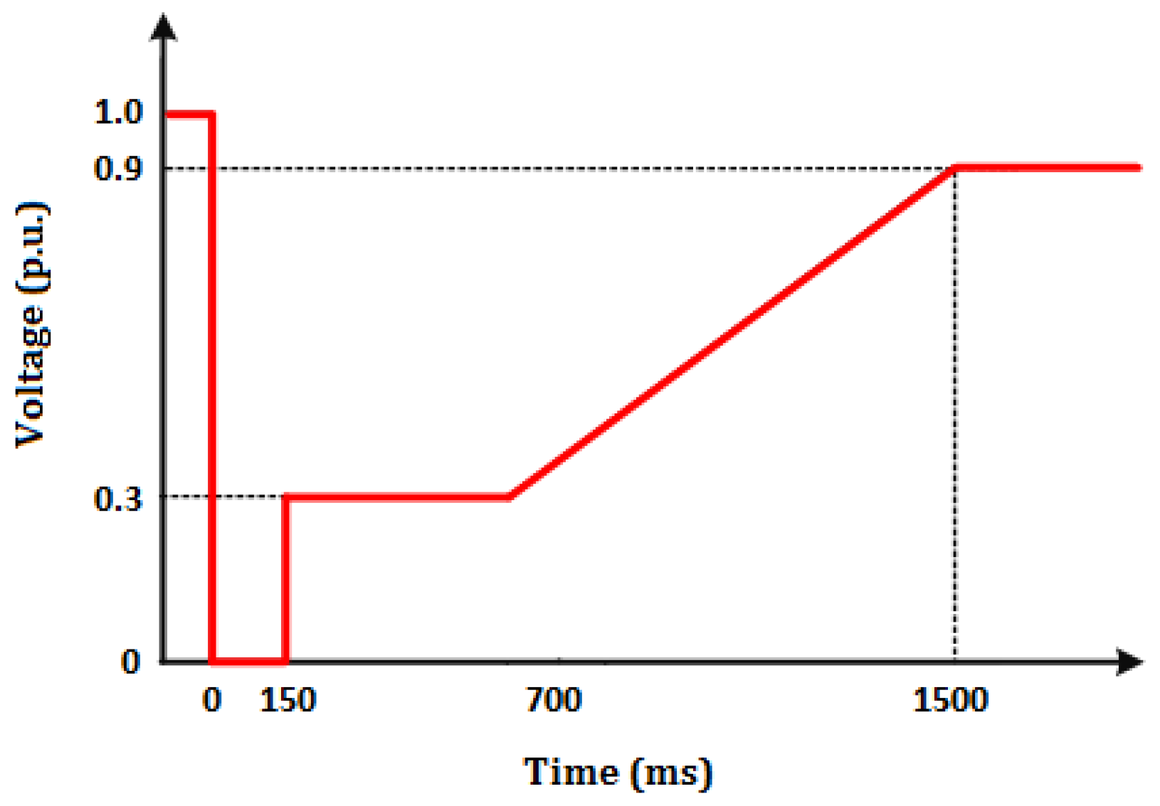
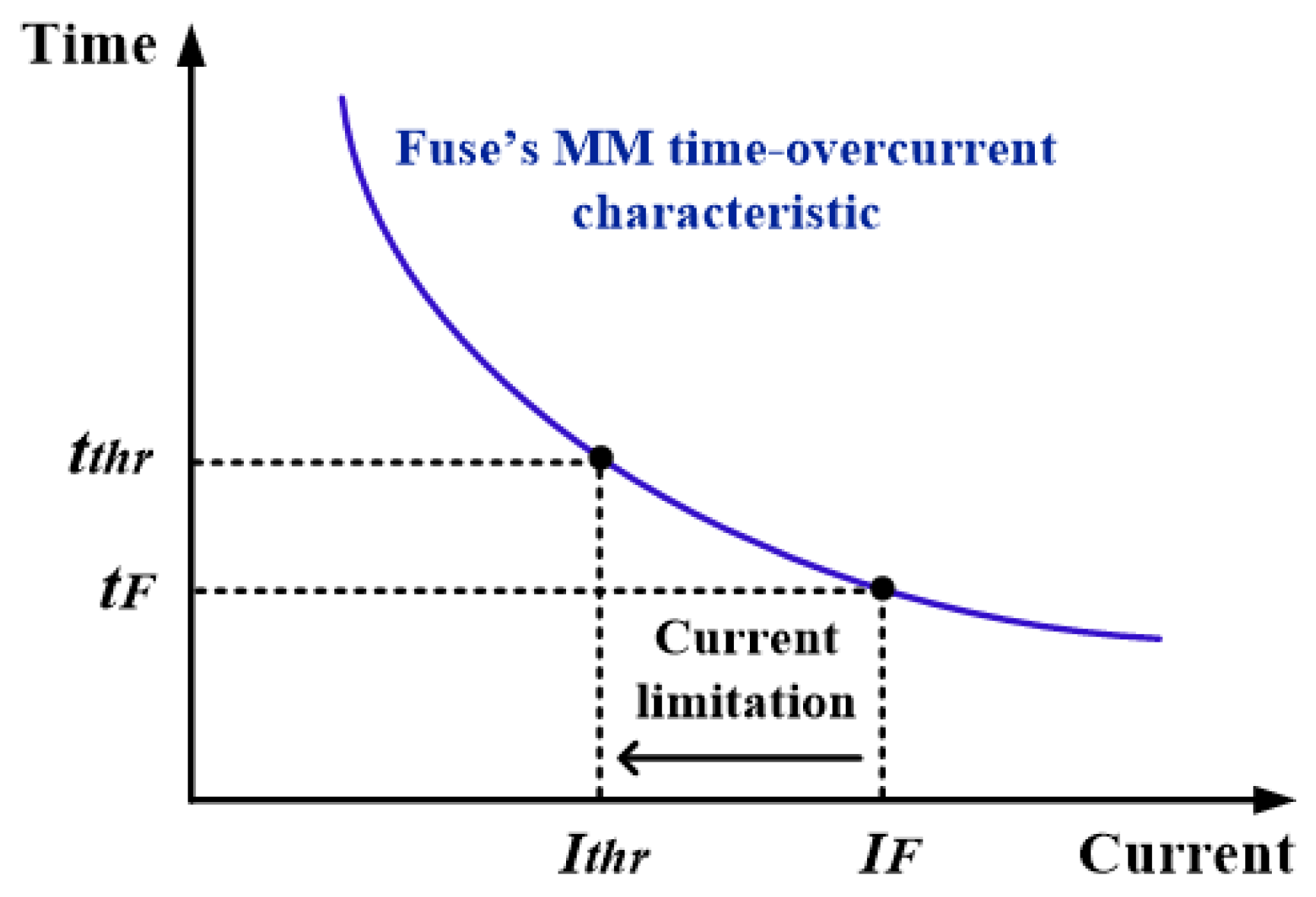
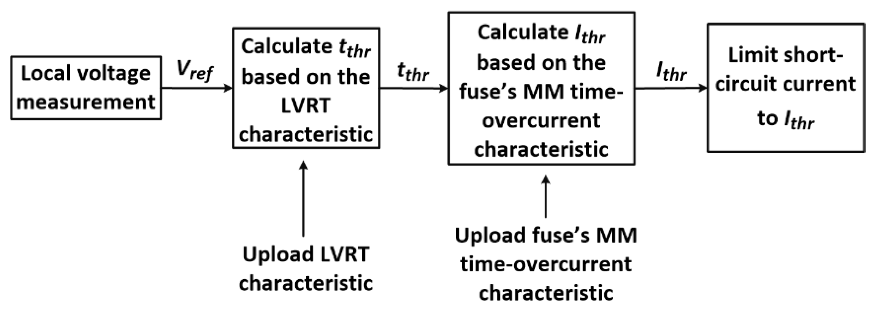
2.2. Basic Operation Principles of the Proposed Concept

In this work, we propose installing a CLD at the fuse location (directly upstream to the fuse, as shown in Figure 1), in order to provide a solution which prevents unintentional islanding, without requiring the modification of the existing protection scheme.
The purpose of the designed CLD is to suitably limit the short-circuit current flowing through the fuse during faults, so as to delay its melting and achieve coordination with the LVRT operation of the PV-unit; in that way, the PV-unit will be allowed to disconnect first (after remaining connected for as long as it is imposed by the LVRT requirements), preventing unintentional islanding.
The basic operation principle of the proposed CLD is described with the aid of Figure 3 and Figure 4. Figure 3 illustrates a generic time-overcurrent characteristic of a fuse, while Figure 4 presents the flowchart of the proposed CLD operation logic. Considering Figure 3, tF is the melting time of the fuse, resulting from its time-overcurrent characteristic and the short-circuit current IF, whereas tthr is the required time duration of the PV-connection that is imposed by the adopted LVRT characteristic and the voltage drop at PCC. If tF < tthr holds, then the fuse melts before the disconnection of the PV, leading to an unintentional islanding condition. By installing the proposed CLD at the fuse location, we can limit IF to a lower value (i.e., Ithr), increasing the melting time of the fuse to a value larger than or at least equal to tthr. Subsequently, the fuse melting is suitably delayed, allowing for the PV to disconnect first, after meeting the LVRT requirements. Note that the minimum-melting (MM) time-overcurrent characteristic of the fuse (also depicted in Figure 3) has to be taken into account instead of its total-clearing (TC) characteristic, as a safe-side consideration to ensure that the PV-unit is disconnected (after complying with the LVRT requirements) prior to the fuse melting.
Apparently, a critical design parameter is the CLD current threshold Ithr. Ithr is adaptively determined in this study, based on the voltage measured at the CLD location, which coincides with the fuse location. The adopted approach intends to directly link Ithr to the LVRT characteristic of the PV-unit. The process to acquire Ithr value is shown in the flowchart of Figure 4 and is briefly described as follows: Initially, tthr is calculated based on the measured voltage and the LVRT characteristic. Next, using the calculated tthr value, we can determine the maximum current for which the fuse melts subsequent to the time indicated by the LVRT requirements. This current value is set as the current threshold Ithr of the CLD and is determined based on tthr and the MM time-overcurrent characteristic of the fuse. In order to achieve the adaptive approach mentioned above, the LVRT characteristic as well as the MM time-overcurrent characteristic of the fuse should be beforehand uploaded into the CLD microprocessor, e.g., in the form of a look-up-table. This task can be easily performed in any microprocessor. It is also noted that Vref in Figure 4 is the reference voltage for compliance with LVRT requirements, as indicated by the grid code adopted in each case. For example, according to [37], Vref corresponds to the lowest line-line voltage.
It should be mentioned, that the undervoltage protection characteristic of the PV-unit is assumed to coincide with the adopted LVRT characteristic, implying that the PV-unit disconnects (or at least ceases energization) as soon as the time duration imposed by the LVRT characteristic elapses; this undervoltage characteristic is always embedded in the PV control-units. Nonetheless, the proposed methodology is applicable, without any modification, to any undervoltage protection characteristic, assuming that this characteristic is wide enough to comply with the LVRT requirements.
It has to be noted that measuring the voltage at the CLD/fuse location, instead of the PCC of the PV-unit (which is actually of interest), is a compromise made to avoid the use of communication link between the CLD and the PV-unit (and thus to avoid increasing the cost of the proposed scheme). However, this is a safe-side compromise, since, for the vast majority of fault cases, the voltage at the CLD/fuse location is expected to be equal to or greater than the voltage at the PCC of the PV-unit. This assumption stems from the short-circuit contribution of a PV-unit, which is considerably lower compared to that of the, much stronger, external grid source directly upstream to the CLD/fuse. Hence, the calculated tthr will be larger than (or at least close to) the actual tthr resulting from the actual PCC voltage. As such, the PV-unit will be allowed to disconnect first, as desired. Even in the worst-case scenario, where the PCC voltage is greater than the voltage at CLD/fuse location, the voltage difference is expected to be rather small and can be easily compensated by considering an additional safety margin in the voltage measured by the CLD. The above assumption is further supported through extensive simulation results, presented in Section 4.4.

3. Description of the Proposed CLD from a Power Electronics Perspective

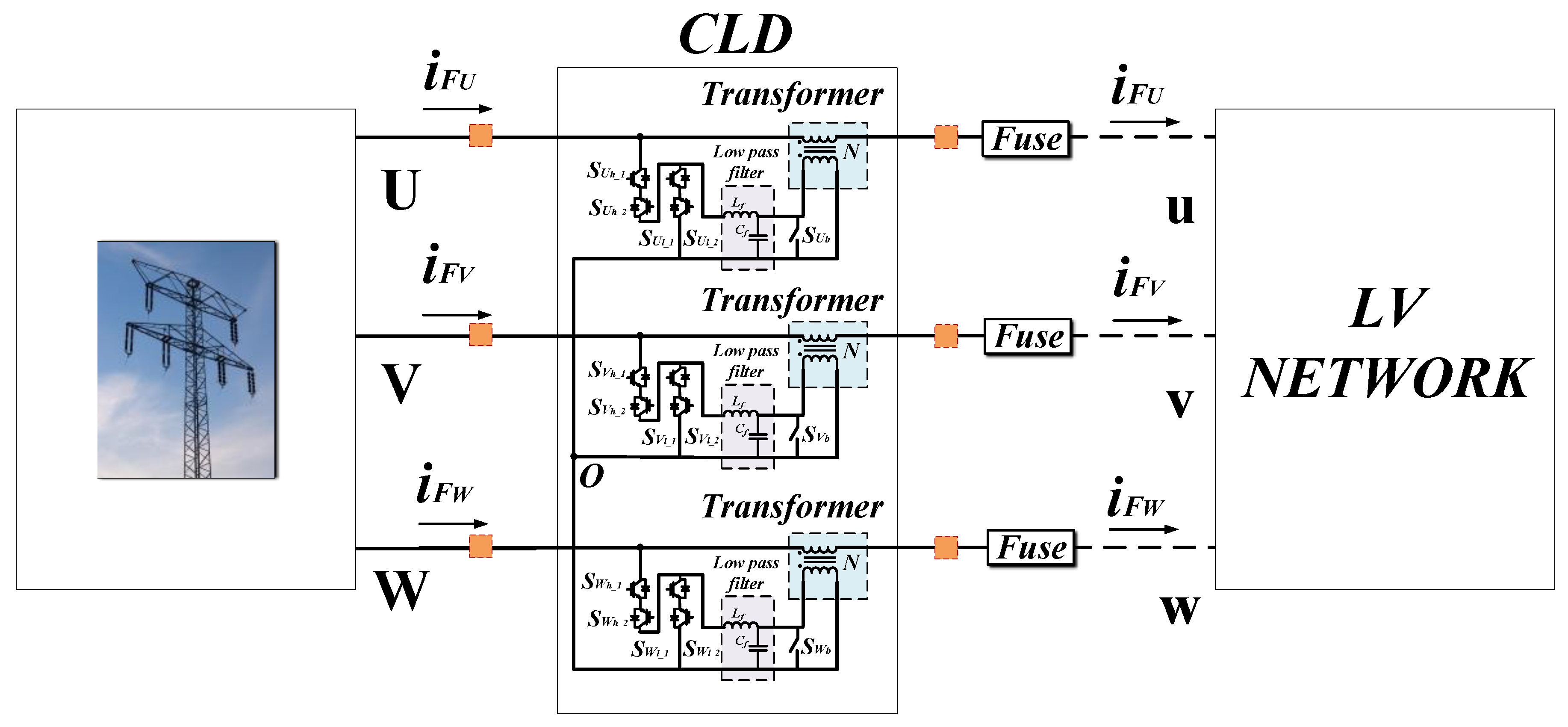
3.1. Topology Selection

Various current-limiting topologies have been proposed over the past years in scientific literature. A review of those is presented in [38], focusing on power flow control in the ac transmission systems and power conditioning in distribution systems. As part of the approach used in the present work, the CLD is based on the buck converter, utilizing only five active switches per phase [39]. In principle, the proposed CLD topology opposes a voltage to the ac-mains through a transformer, in order to limit the short-circuit current during faults. Its equivalent electric diagram is presented in Figure 5, where the following components of the CLD are depicted: The high (Sh_1,2) and low (Sl_1,2) -side power switches (either Insulated Gate Bipolar Transistors, IGBTs, or Metal Oxide Semiconductor Field Effect Transistors, MOSFETs, can be used), the transformer shorting switch (Sb), the low-pass filter (Lf, Cf) and the isolation transformer. Based on the topology of Figure 5, we can extend the proposed solution in a three-phase system. The three-phase version of the proposed solution is presented in Figure 6 and it consists of three single-phase topologies, connected together through the neutral wire. The output neutral-connection of the CLD can be connected with the neutral point of the distribution (substation) transformer. In the next subsection, the operation of the CLD is described, also supported by indicative simulation results.

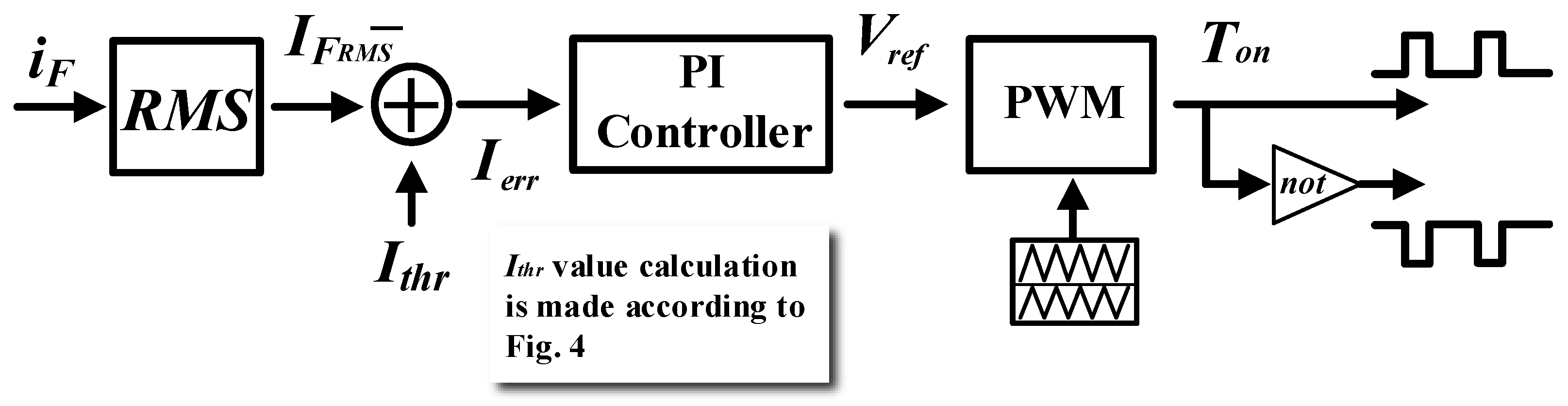
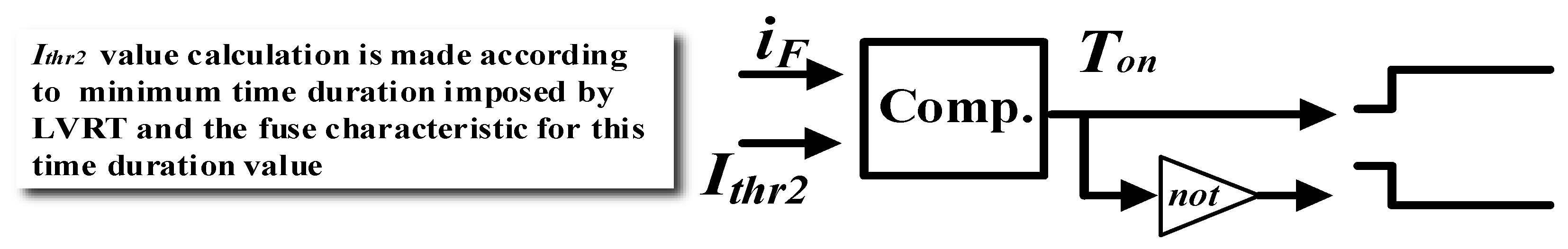
3.2. CLD Operation Description

This Section describes the operation of the proposed CLD in detail; the description is based on the single-phase topology of Figure 5 and is equally valid for the three-phase system. The operation principle of this CLD topology is shown in Figure 7, and it is based on the appropriate control of the high (low-side switches are complementary driven)—side switches of Figure 5, in order to generate the opposing voltage vop (the same principle applies to the three-phase system of Figure 6). Considering the above, the CLD is principally a buck converter, whose output (vop) is connected in series with the grid voltage through a transformer. vop is the output voltage of CLD (after the transformer) which opposes to the grid voltage, whereas vg is the grid voltage at the fuse location; the CLD output voltage opposed grid voltage as it is connected in series with it (see Figure 5); in this work, the series voltage-source connection is used, due to its simple design and control scheme. Assuming that the switching frequency of CLD is much higher than the line frequency and the filter does not impose any magnitude or phase differentiation, the mean value of buck and CLD output voltage (vop and vop, respectively), over a switching period, is given by Equations (1) and (2). Their magnitudes, Vop and Vop are given by Equations (3) and (4).
v o p = d · v L N
v o p = N · v o p
V o p = d · V L N
V o p = N · V o p = d · V L N
d = T h _ o n / T S W
d = 1 d
In the above equations, d and d’ are the duty cycles of the high-side and low-side switches, respectively, given by Equations (5) and (6), Th_on is the on-state time of high switches, and Tsw is the switching period of the Pulse Width Modulation (PWM) modulator. Finally, N is the turn ratio of the transformer.
It is also noted that switch Sb shorts the secondary side of the CLD transformer, which in turn results in a zero vop voltage and the effective deactivation of CLD; it is recommended to keep Sb closed during the normal operation. As the switches operate in a high frequency (~10–20 kHz), a low pass L-C filter is also used to filter out the higher order harmonics; it should be noted that the filter stage can be omitted for PWM switching frequencies higher than 20 kHz.
Based on the circuit of Figure 5, the fuse current (iF) is given by:
i F = V L N V T h e v V o p Z
where vThev and z are the equivalent Thevenin voltage and impedance of the LV network, respectively, given by:
v g = i F · z + v T h e v
According to Equations (4) and (7), the fuse current can be limited to the desired level by controlling the duty cycle of CLD high-side switches (the same principle also applies for the three-phase system). In order to control the fuse current, we have used the control scheme that is depicted in Figure 7.
Its operation is shortly described as follows: The fuse current is sensed and the acquired samples are used to calculate the Root Mean Squre (RMS) value in a “running-window” mode. The RMS value is subtracted from Ithr (Ithr is calculated based on Figure 4) and fed into a proportional-integral (PI) controller. The output of the PI controller output (i.e., Vref) is the desired voltage magnitude of the CLD output. A PWM modulator is finally used to generate the driving pulses of CLD switches.
Finally, Figure 8 illustrates a safety measure against very large fault currents. In such a case, the response time window of the controller is reduced to a few ms, which occasionally might not be enough to limit the fault current prior to the fuse melting. To overcome this problem, the fuse current is compared to a threshold value which immediately activates the CLD (it sets high-side switch permanently on), bypassing so the PI controller and the slow RMS estimator. This threshold value should be calculated based on the minimum time duration imposed by the LVRT characteristic and the corresponding current value of the fuse time-overcurrent characteristic. Indicative simulation results of the CLD output voltage before the filter stage, the vop, the fuse-current, and the CLD high-side switch currents, are presented in Figure 9a,b. These figures demonstrate the CLD operation, both during steady state and transient conditions; CLD parameters are: N = 1, Tsw = 100 us, Cf = 200 nF, Lf = 400 uH. The LV network impedance during the normal operation is znormal = 2.45 Ohm.
In order to test the CLD response we assume a fault that results in a very large voltage drop of vg (below 0.3 pu). According to the LVRT requirements of Figure 2 a grid-tied inverter in this fault should remain connected for 150 ms (tthr). Referring to Figure 4, Ithr is defined based on tthr and fuse characteristic. Assuming the fuse (ΜΜ) characteristic of Figure 10 (which will be also considered in the simulation study of the next section), we calculate the Ithr value to be around 2200 A. This is the current value that the CLD should maintain in this example. The sequence of events for this demonstration example is the following: During the time interval 0 ≤ t < 0.2 s, the system operates under the normal voltage level, assuming an equivalent Thevenin resistance of znormal = 2.45 Ohm. At t = 0.2 s, a fault occurs in the low-voltage network. The fault results in an equivalent resistance zfault of 0.01 Ohm. Subsequently, the voltage level drops and the CLD is activated after having set the Ithr value accordingly. At ~t = 0.21 s, the fuse RMS current exceeds Ithr and the high-side switch starts operating.
Figure 9a illustrates the CLD output voltage before and after the filter stage, during the time-interval 0 ≤ t < 0.3 s. During the normal operation, the CLD output voltage is approximately zero. When the CLD is activated, its output voltage is either NvLN or zero, depending on the high-side switch state. Indicative results of the high-side switch and fuse current are shown in Figure 9b. According to Figure 9b, the fuse current is effectively limited by CLD to 2200 RMS (or 3160 peak A), supporting the effectiveness of proposed CLD to limit the fault current to the desired value.
The current flowing through the CLD switches is also depicted in Figure 9b. It can be noticed that, after fault occurrence, a high current flows through the CLD switches for a considerable time duration. Consequently, CLD sizing should be made, taking into account the current value of the fuse time-overcurrent characteristic that corresponds to the minimum time duration imposed by LVRT requirements.
The above simulation results are related to the operation of the proposed CLD from a power electronics perspective. In the following section, extensive simulation results are presented, examining the CLD from a power system perspective.

4. Performance Evaluation from a Power System Perspective: Results and Discussion

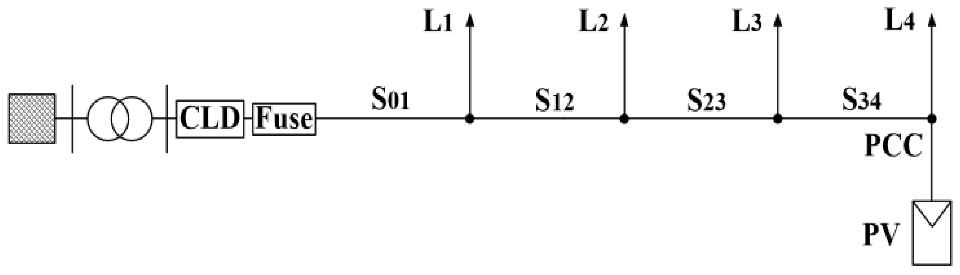
4.1. Test-System Description

The proposed CLD has been modeled and tested on the 50 Hz, 0.4 kV, LV distribution feeder of Figure 11, using MATLAB/Simulink. The test feeder has been modeled based on actual data (concerning external grid, distribution transformer, distribution line, protection means etc.) of European LV distribution systems, which have been received from the Hellenic Distribution Network Operator S.A. (HEDNO S.A.) and [30].
A 50-kW PV-unit is assumed to be connected to the endpoint of the feeder. The PV-unit is designed to comply with the LVRT requirements, which, in this work, are indicatively assumed to be the requirements of BDEW [37] (see the corresponding LVRT characteristic in Figure 2), extended to LV distribution systems. It should be noted though that the proposed concept can be equally applied considering any LVRT characteristic. Furthermore, the PV-unit has been designed to provide dynamic voltage support, although the detailed design of this function is out of the scope of the present work.
The feeder is protected by a 3 × 250 A gL fuse installed at its departure. Both the MM and the TC time-overcurrent characteristics of the fuse are shown in Figure 10, as provided by the library of the DIgSILENT PowerFactory software. It is noted that only the MM characteristic of the fuse (instead of the delayed TC characteristic) is taken into account (and therefore modeled) for the simulation study. This approach allows us to test the proposed CLD under the worst-case scenario (in terms of fuse quick melting) and ensure that the PV-unit will be disconnected prior to the fuse melting, preventing unintentional islanding (see Section 2). Finally, according to Section 2, the proposed CLD is placed at the fuse location (directly upstream to the fuse); the electrical characteristics of the system under study are summarized in Table 1.

4.2. Simulation Results

The effectiveness of the proposed CLD has been thoroughly evaluated against both balanced, i.e., three-phase (3PH), and unbalanced, i.e., single-line-ground (SLG), faults at the critical (marginal) points of the examined feeder. These points are the fuse location (directly in front of the fuse) and the PCC of the PV-unit. Practically solid faults are simulated, as these faults are more prone to causing “early” fuse melting. Moreover, each fault is simulated with and without the proposed CLD. The examined study cases are summarized in Table 2.
The simulation results for study cases 1–8 are depicted in Figure 12, Figure 13, Figure 14, Figure 15, Figure 16, Figure 17, Figure 18 and Figure 19, respectively. The following quantities are shown, supporting the operation of CLD: Root-mean-square (RMS) voltage at fuse location; RMS current flowing through the fuse, current threshold Ithr of CLD (only in the study cases where CLD is used, i.e., study cases 2, 4, 6, and 8); RMS voltage at the PCC of the PV-unit. Moreover, the state of the fuse and the PV circuit breaker (CB) (“0” when the protection means conducts current and “1” when it does not conduct current) are also presented. Note that the voltage measured at the fuse location and at the PCC of the PV-unit is the lowest line-line voltage, which is the reference voltage (Vref) for compliance with LVRT requirements according to [37]. Moreover, during SLG faults, the current illustrated corresponds to the faulted phase (phase a). All faults occur at t = 0.2 s.

4.3. Discussion

Based on the simulation results illustrated in Figure 12, Figure 13, Figure 14, Figure 15, Figure 16, Figure 17, Figure 18 and Figure 19, the following two critical observations can be made:
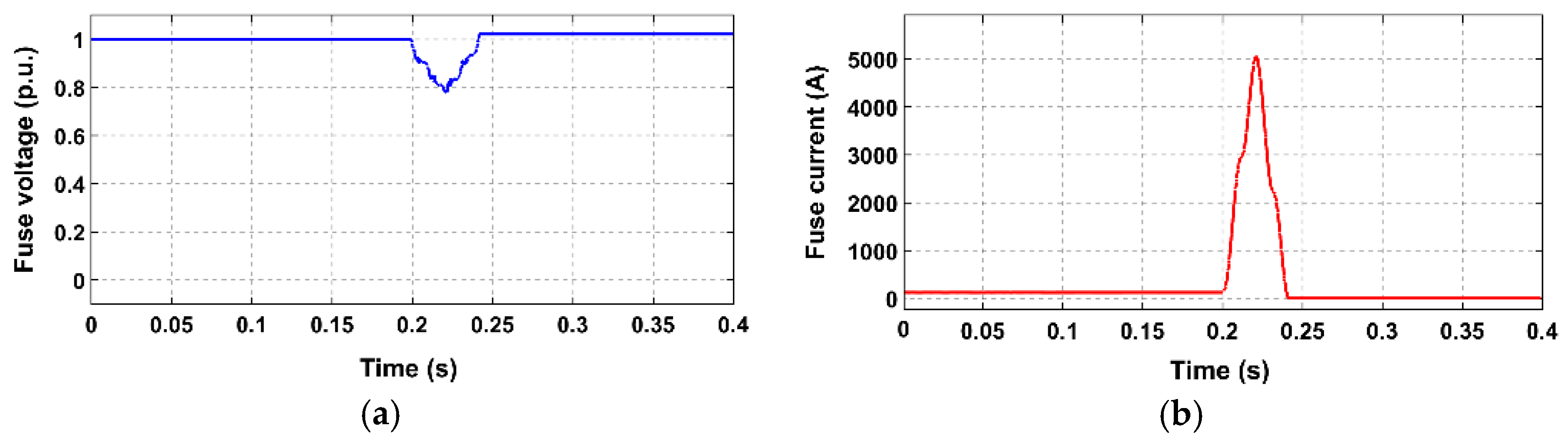
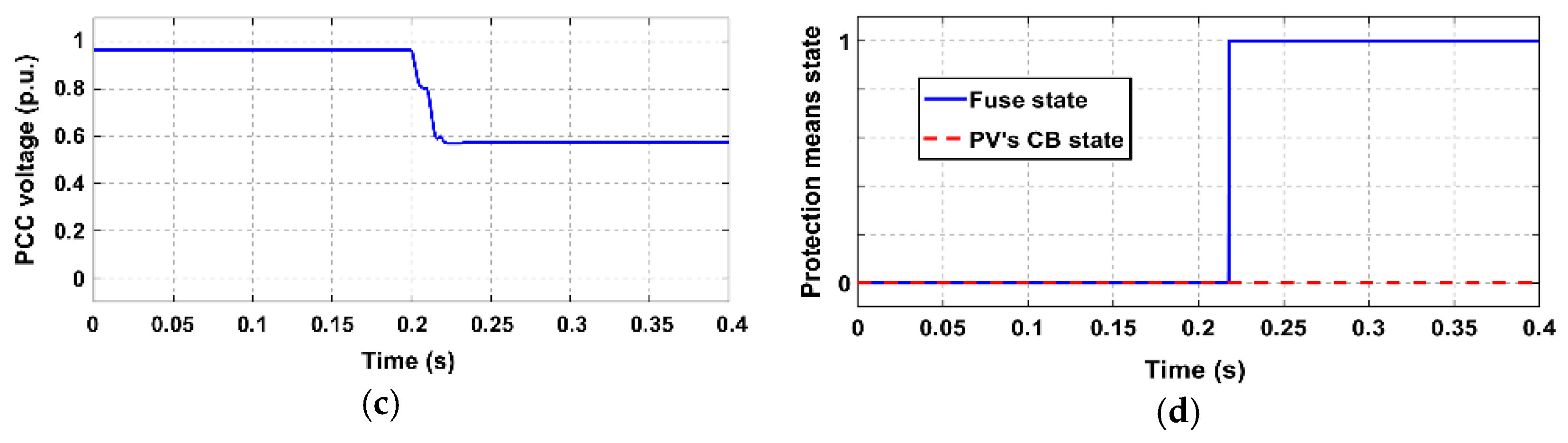
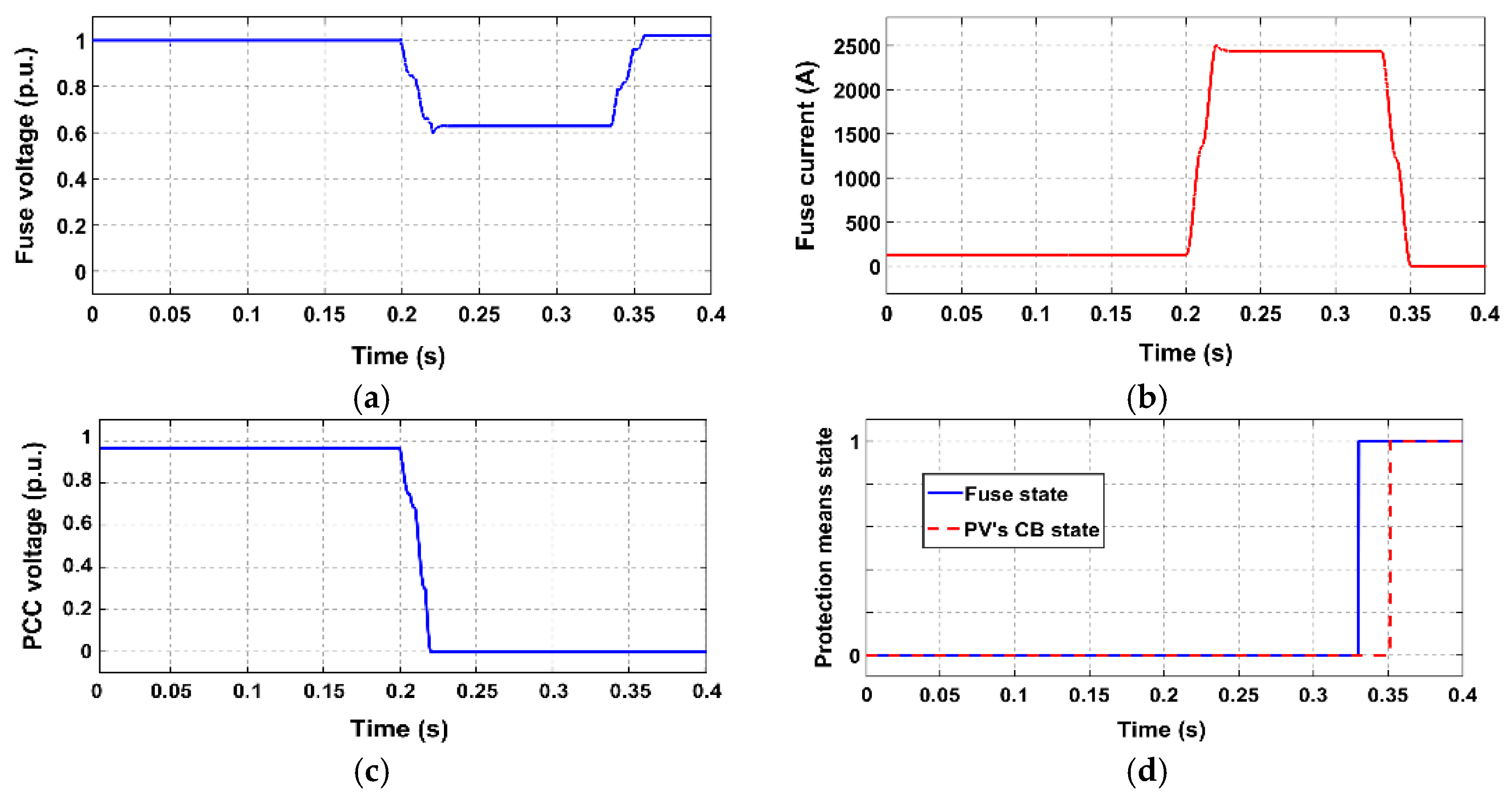
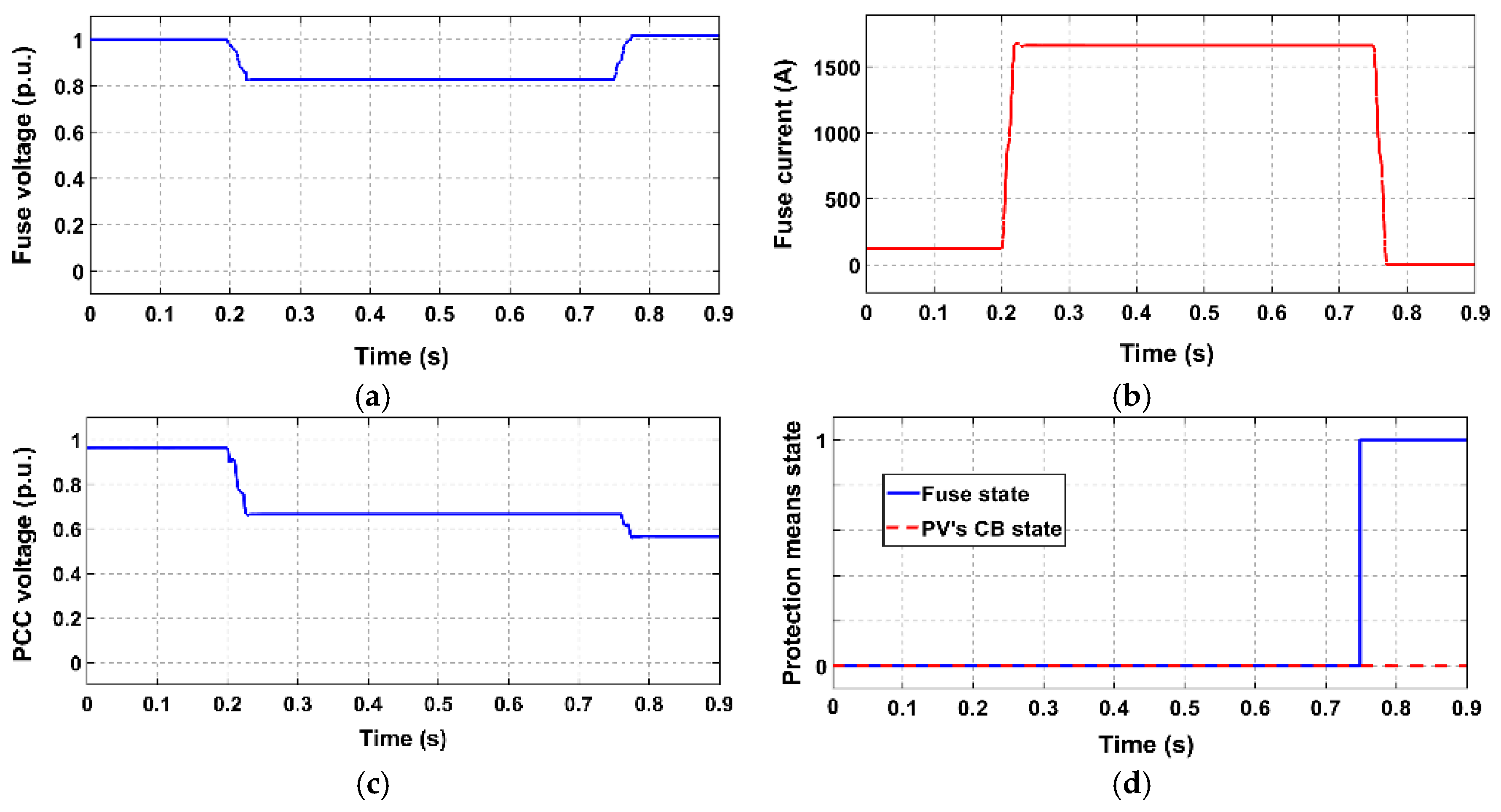
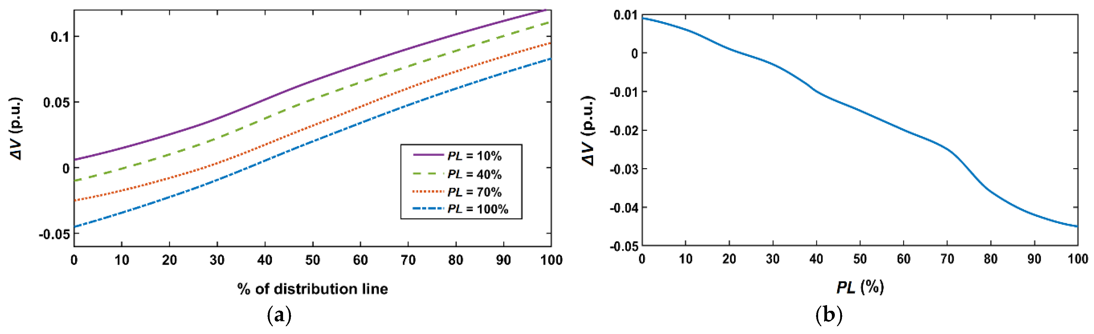
  • In all the examined study cases where CLD is not applied, the fuse melts before the PV-unit disconnects, so, the desired fuse-PV coordination is violated. As can be seen in Figure 12b, Figure 14b, Figure 16b and Figure 18b, the short-circuit current flowing through the fuse becomes high after fault inception, leading to an “early” fuse melting. This results in a prolonged connection of the PV-unit to the network, after fuse melting (unintentional islanding). The duration of this undesirable protracted PV-connection is greater during SLG faults (which are the most frequently occurring in actual distribution networks). This is because, in these cases, Vref at the PCC of the PV-unit remains relatively high after fuse melting (as only the faulted phase is disconnected), unlike 3PH-fault cases, where the voltage drops considerably.
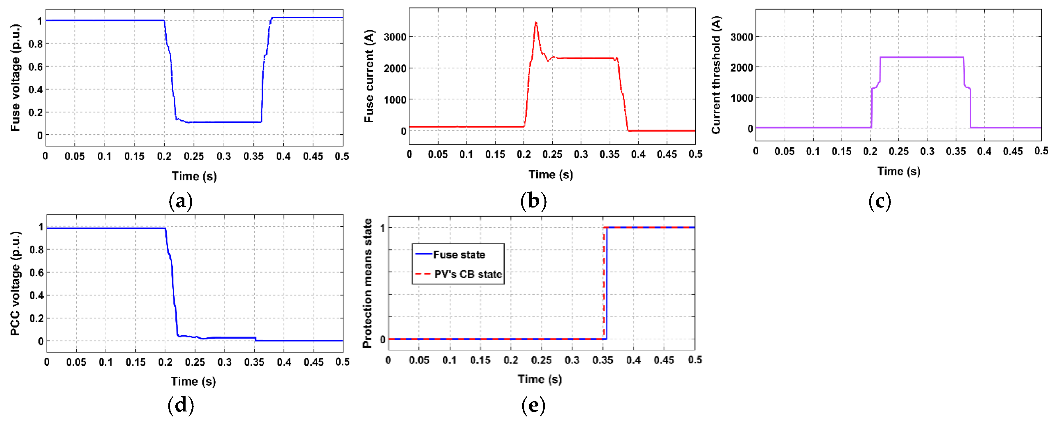
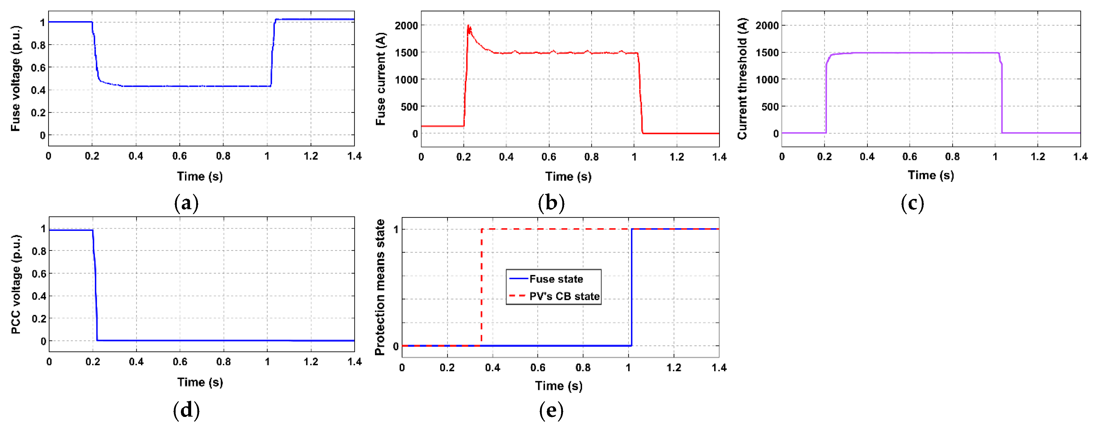
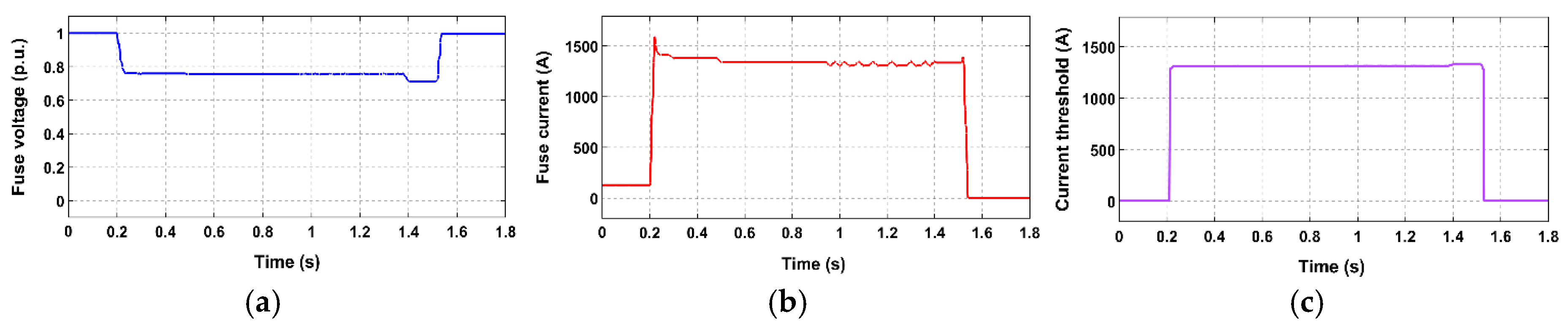
  • When the CLD is applied, the above problem is solved for all the examined cases, even for the most severe faults (i.e., faults occurring directly in front of the fuse). Specifically, after fault occurrence, the CLD acts rapidly, limiting the fault current that flows through the fuse to the calculated current threshold Ithr; the drastic limitation of the fuse current by CLD is effectively shown in Figure 13b, Figure 15b, Figure 17b and Figure 19b. Concluding, the fuse melts after the PV-unit disconnects, letting this unit to fully comply with the LVRT requirements. At the same time, since the PV-unit disconnects first, unintentional islanding is certainly avoided.
All the above observations are further supported by Figure 12d, Figure 13e, Figure 14d, Figure 15e, Figure 16d, Figure 17e, Figure 18d and Figure 19e, where the state of protection means is shown.
It is worth noting that, in order to ensure that the proposed scheme will always operate properly, a safety margin (additional voltage) of 0.01 p.u. has been considered in the voltage measured by the CLD (Vref), as mentioned in Section 2.2. It is reminded that this safety margin is related to the much less frequent cases where a negative voltage difference ΔV between the fuse voltage and the PCC voltage (meaning that fuse voltage < PCC voltage) appears. The voltage safety margin of 0.01 p.u. is selected after having simulated faults of all types in front of the fuse. Note that this is the fault position that reasonably results in the greatest negative voltage difference ΔV (if any) between the fuse voltage and the PCC voltage.
The required voltage safety margin is notably low, which confirms the initial assumption, made in Section 2.2: In a typical LV distribution feeder, the voltage at the PCC of a PV-unit is expected to be lower than (or at least very close to) the grid voltage at fuse location. This issue is further analyzed in the next subsection.

4.4. Additional Simulation Results

In this subsection, additional simulations are performed, in order to further analyze some noteworthy aspects of the proposed concept.

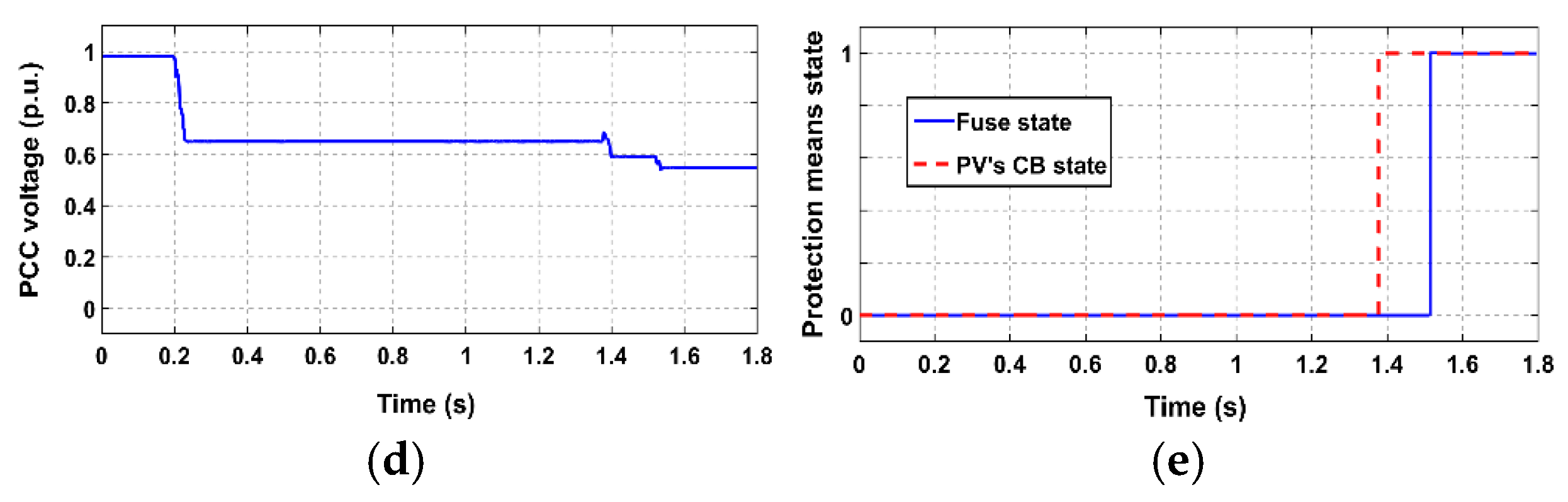
4.4.1. Voltage Difference between CLD/Fuse Location and PCC Location

As mentioned at the end of the previous subsection, a very low maximum absolute negative voltage difference between the CLD/fuse location and the PCC of the PV-unit might be observed in the system under study. Hence, this issue can be addressed by considering a slight safety margin in the voltage measured by the CLD.
In general, the amount of this voltage difference ΔV depends on the fault type, the fault position and the PV rated power (i.e., the PL). To further analyze this aspect, faults of all types were simulated along the examined distribution line, varying the rated power of the PV-unit. During these simulations, negative ΔV values appeared only for certain SLG faults (ΔV was always positive for the rest fault types, as desired).
Figure 20a shows ΔV as a function of the length of the examined distribution line (shown as a percentage of the total line length) for different PL, considering SLG faults. Figure 20b focuses solely on the most unfavorable fault-type/fault-location conditions regarding the appearance of negative ΔV (i.e., a SLG fault in front of the CLD/fuse), considering PL 0–100%. Based on these two figures, the following conclusions can be derived:
  • ΔV drastically varies from negative to positive as fault position moves away from the CLD/fuse location (0% of the distribution line).
  • ΔV drastically varies from negative to positive as PL is decreased.
  • Even the greatest absolute negative ΔV value appearing during the simulations is quite low (~ 0.045 p.u.)
All in all, negative ΔV values are not likely in typical LV distribution systems with PV-unit(s), since such a phenomenon concerns in very specific conditions (i.e., specific fault type, fault position quite close to the CLD/fuse, and quite high PL at the same time). However, even in the worst-case scenario, the absolute negative ΔV seems to be very small and can be easily addressed considering a slight safety margin in the voltage measured by the CLD, as we did in the previous subsection. Furthermore, it is reminded that the proposed CLD operates based on the MM characteristic of the installed fuse, as a strict/safe-side assumption to ensure fuse-PV coordination. Nevertheless, since the actual clearing time of the fuse can reach the time resulting from its TC characteristic, the time between the MM time and the actual clearing time of the fuse serves as an additional safety margin for this purpose (although we do not rely solely on this safety margin).

4.4.2. Impact of the Delayed Fuse Melting on the Equipment Through-Fault Damage

Although the proposed scheme aims at delaying the fuse melting, so as to achieve fuse-PV coordination and prevent unintentional islanding, this delay should not compromise the LV distribution system equipment, in terms of through-fault damage. In the following, the fulfillment of this requirement is checked using the damage curves of the two basic elements of the examined LV distribution system, i.e., the distribution transformer and the distribution line. Figure 21a,b show the damage curve of the former and the latter element, respectively, extracted using DIgSILENT PowerFactory.
Table 3 gives the steady-state fault current flowing through the fuse for the study-cases that have been examined in Section 4.2 and are related to the CLD. The corresponding maximum allowable clearing time values, resulting from the damage curve of the distribution transformer and the damage curve of the distribution line, are also presented. Finally, in each case, Table 3 gives the melting time of the fuse as well as the clearing time of the fuse resulting from its MM and TC characteristic, respectively; it is reminded that the CLD control algorithm takes into account only the MM characteristic, as it corresponds to the most challenging case for the CLD response.
Based on the data presented in Table 3, it is concluded that both the MM and the TC time of the fuse are always safely below the corresponding maximum allowable clearing time indicated by the damage curve of the distribution transformer. Moreover, in all the examined cases, the fault current does not even intersect the distribution line damage curve (noted as “N/I” in Table 3). It is, therefore, evident that the operation of the proposed CLD is by no means detrimental for the equipment of the examined LV distribution system.

5. Conclusions

This paper proposes a CLD along with an appropriate control algorithm, aiming to prevent unintentional islanding by coordinating the fuse protecting a LV distribution line with any downstream PV-unit (in accordance with the LVRT requirements for the PV-unit).
The CLD, placed at the fuse location, is designed to take into account both the time-overcurrent characteristic of the fuse and the LVRT characteristic of the adopted grid code. In that way, it ensures enough time for the PV-unit to comply with the LVRT requirements and disconnect, before fuse melting; as a result, prolonged unintentional energization of the isolated feeder is avoided. The aforementioned two characteristics constitute the main data uploaded to the proposed CLD by the user, since the CLD calculates its current threshold adaptively, based on the voltage continuously measured at its location. This is an easy task to be performed by any microprocessor.
Extensive simulation tests have been performed to demonstrate the problem of unintentional islanding, resulting from fuse-PV coordination loss. These simulations also validate the effectiveness of the proposed CLD at dealing with this issue, for a variety of critical fault cases. Specifically, it is shown that, when the proposed CLD is not considered, the fuse always melts before the PV-unit disconnects; the PV-unit remains connected after fuse melting, leading to unintentional islanding. The duration of the unintentional islanding situation is greater during SLG faults. On the other hand, when the CLD is considered, fuse melting is always properly delayed, letting the PV-unit disconnect first. In this way, unintentional islanding is avoided. Moreover, it is shown that the use of the voltage measured at the CLD/fuse location instead of the voltage measured directly at the PCC of the PV-unit is a robust solution to avoid the use of communication means, given that (i) for the vast majority of possible fault cases, the fuse voltage is equal to or greater than the PCC voltage; (ii) even in the worst-case scenario, the PCC voltage is only slightly greater than the fuse voltage; and (iii) any negative ΔV (see Section 4) can be easily compensated by, primarily, considering a small safety margin in the voltage measured by the CLD and, secondarily, by the inherent time margin between the MM and the actual clearing time of the fuse. Finally, it is shown that the delayed melting of the fuse due to short-circuit current limitation does not affect protection speed in terms of possible equipment through-fault damage.

Author Contributions

Conceptualization, D.V., A.T. and N.P.; Methodology, D.V. and A.T.; software, D.V. and I.P.; Validation, D.V. and A.T.; Formal analysis, D.V. and A.T.; data curation, C.K.; writing—original draft preparation, D.V. and A.T.; writing—review and editing, D.V., A.T. and N.P.; supervision, N.P.

Funding

This research is co-financed by Greece and the European Union (European Social Fund-ESF) through the Operational Program “Human Resources Development, Education and Lifelong Learning 2014–2020” in the context of the project “DGRES-PRO” (MIS 5006210).

Conflicts of Interest

The authors declare no conflict of interest.

References

  1. Yang, Y.; Enjeti, P.; Blaabjerg, F.; Wang, H. Wide-scale adoption of photovoltaic energy: Grid code modifications are explored in the distribution grid. IEEE Ind. Appl. Mag. 2015, 21, 21–31. [Google Scholar] [CrossRef]
  2. Photovoltaics, D.G.; Storage, E. IEEE Standard for Interconnection and Interoperability of Distributed Energy Resources with Associated Electric Power Systems Interfaces; IEEE Standard: Piscataway, NJ, USA, 2018; pp. 1547–2018. [Google Scholar]
  3. Sadeghkhani, I.; Golshan, M.E.H.; Mehrizi-Sani, A.; Guerrero, J.M. Low-voltage ride-through of a droop-based three-phase four-wire grid-connected microgrid. IET Gen. Transm. Distrib. 2018, 12, 1906–1914. [Google Scholar] [CrossRef]
  4. Kyritsis, A.; Voglitsis, D.; Papanikolaou, N.P.; Tselepis, S.; Christodoulou, C.; Gonos, I.; Kalogirou, S.A. Evolution of PV systems in Greece and review of applicable solutions for higher penetration levels. Renew. Energy 2017, 109, 487–499. [Google Scholar] [CrossRef]
  5. Perpinias, I.; Papanikolaou, N.P.; Tatakis, E.C. Optimum design of low-voltage distributed photovoltaic systems oriented to enhanced fault ride through capability. IET Gen. Transm. Distrib. 2015, 9, 903–910. [Google Scholar] [CrossRef]
  6. Yang, Y.; Blaabjerg, F.; Wang, H. Low-voltage ride-through of single-phase transformerless photovoltaic inverters. IEEE Trans. Ind. Appl. 2014, 50, 1942–1952. [Google Scholar] [CrossRef]
  7. Yang, Y.; Wang, H.; Blaabjerg, F. Reactive power injection strategies for single-phase photovoltaic systems considering grid requirements. IEEE Trans. Ind. Appl. 2014, 50, 4065–4076. [Google Scholar] [CrossRef]
  8. Mango, F.; Liserre, M.; Aquila, A.; Pigazo, A. Overview of anti-islanding algorithms for PV systems. Part I: Passive methods. In Proceedings of the 12th International Power Electronics and Motion Control Conference, (PEMC), Portoroz, Slovenia, 30 August–1 September 2006. [Google Scholar]
  9. Voglitsis, D.; Valsamas, F.; Rigogiannis, N.; Papanikolaou, N. On the Injection of Sub/Inter-Harmonic Current Components for Active Anti-Islanding Purposes. Energies 2018, 11, 2183. [Google Scholar] [CrossRef]
  10. Reigosa, D.; Briz, F.; Blanco, C.; Guerrero, J.M. Islanding detection in three-phase and single-phase systems using pulsating high-frequency signal injection. IEEE Trans. Power Electron. 2015, 30, 5659–5666. [Google Scholar] [CrossRef]
  11. Voglitsis, D.; Papanikolaou, N.P.; Kyritsis, A. Active cross-correlation anti-islanding scheme for PV module-integrated converters in the prospect of high penetration levels and weak grid conditions. IEEE Trans. Power Electron. 2019, 34, 2258–2274. [Google Scholar] [CrossRef]
  12. Voglitsis, D.; Valsamas, F.; Rigogiannis, N.; Papanikolaou, N.P. On harmonic injection anti-islanding techniques under the operation of multiple DER-inverters. IEEE Trans. Energy Convers. 2019, 34, 455–467. [Google Scholar] [CrossRef]
  13. Khodaparastan, M.; Vahedi, H.; Khazaeli, F.; Oraee, H. A novel hybrid islanding detection method for inverter-based DGs using SFS and ROCOF. IEEE Trans. Power Del. 2017, 32, 2162–2170. [Google Scholar] [CrossRef]
  14. Dietmannsberger, M.; Grumm, F.; Schulz, D. Simultaneous implementation of LVRT capability and anti-islanding detection in three-phase inverters connected to low-voltage grids. IEEE Trans. Energy Convers. 2017, 32, 505–515. [Google Scholar] [CrossRef]
  15. Boemer, J.C.; Walling, R. DER ride-through performance categories and trip settings. In Proceedings of the PJM Ride-Through Workshop, Philadelphia, PA, USA, 1–2 October 2018. [Google Scholar]
  16. Walling, R.; Ellis, A.; Gonzalez, S. Implementation of Voltage and Frequency Ride-Through Requirements in Distributed Energy Resources Interconnection Standards; Sandia National Laboratories: Albuquerque, NM, USA, 2014; pp. 2014–3122.
  17. IEEE Standards Board. IEEE Standard for Interconnecting Distributed Resources with Electric Power Systems; IEEE Standard: Piscataway, NJ, USA, 2003; pp. 1547–2003. [Google Scholar]
  18. Bollen, M.H.; Hassan, F. Integration of Distributed Generation in the Power System; Wiley-IEEE Press: New York, NY, USA, 2011. [Google Scholar]
  19. Dehghanpour, E.; Karegar, H.K.; Kheirollahi, R.; Soleymani, T. Optimal coordination of directional overcurrent relays in microgrids by using cuckoo-linear optimization algorithm and fault current limiter. IEEE Trans. Smart Grid 2018, 9, 1365–1375. [Google Scholar] [CrossRef]
  20. Papaspiliotopoulos, V.A.; Korres, G.N.; Kleftakis, V.A.; Hatziargyriou, N.D. Hardware-in-the-loop design and optimal setting of adaptive protection schemes for distribution systems with distributed generation. IEEE Trans. Power Del. 2017, 32, 393–400. [Google Scholar] [CrossRef]
  21. Nikolaidis, V.C.; Papanikolaou, E.; Safigianni, A.S. A communication-assisted overcurrent protection scheme for radial distribution systems with distributed generation. IEEE Trans. Smart Grid 2016, 7, 114–123. [Google Scholar] [CrossRef]
  22. Nikolaidis, V.C.; Tsimtsios, A.M.; Safigianni, A.S. Investigating particularities of infeed and fault resistance effect on distance relays protecting radial distribution feeders with DG. IEEE Access 2018, 6, 11301–11312. [Google Scholar] [CrossRef]
  23. Liu, Z.; Høidalen, H.K.; Saha, M.M. An intelligent coordinated protection and control strategy for distribution network with wind generation integration. CSEE J. Power Energy Syst. 2016, 2, 23–30. [Google Scholar] [CrossRef]
  24. Liu, X.; Shahidehpour, M.; Li, Z.; Liu, X.; Cao, Y.; Tian, W. Protection scheme for loop-based microgrids. IEEE Trans. Smart Grid 2017, 8, 1340–1349. [Google Scholar] [CrossRef]
  25. Aghdam, T.S.; Karegar, H.K.; Zeineldin, H.H. Variable tripping time differential protection for microgrids considering DG stability. IEEE Trans. Smart Grid 2019, 10, 2407–2415. [Google Scholar] [CrossRef]
  26. Han, B.; Li, H.; Wang, G.; Zeng, D.; Liang, Y. A virtual multi-terminal current differential protection scheme for distribution networks with inverter-interfaced distributed generators. IEEE Trans. Smart Grid 2018, 9, 5418–5431. [Google Scholar] [CrossRef]
  27. Kar, S.; Samantaray, S.R.; Zadeh, M.D. Data-mining model based intelligent differential microgrid protection scheme. IEEE Syst. J. 2017, 11, 1161–1169. [Google Scholar] [CrossRef]
  28. Mishra, M.; Rout, P.K. Detection and classification of micro-grid faults based on HHT and machine learning techniques. IET Gen. Transm. Distrib. 2018, 12, 388–397. [Google Scholar] [CrossRef]
  29. Bukhari, S.B.A.; Haider, R.; Zaman, M.S.U.; Oh, Y.; Cho, G.; Kim, C. An interval type-2 fuzzy logic based strategy for microgrid protection. Int. J. Electr. Power Energy Syst. 2018, 98, 209–218. [Google Scholar] [CrossRef]
  30. Glinka, F.; Bertram, R.; Wippenbeck, T.; Erlinghagen, P.; Schnettler, A. Protection of today’s and future low voltage grids with high DG penetration: Laboratory and simulative analysis of blinding of protection with inverters. In Proceedings of the 13th International Conference on Development in Power System Protection (DPSP), Edinburgh, UK, 7–10 March 2016. [Google Scholar]
  31. Yu, J.J.Q.; Hou, Y.; Lam, A.Y.S.; Li, V.O.K. Intelligent fault detection scheme for microgrids with wavelet-based deep neural networks. IEEE Trans. Smart Grid 2019, 10, 1694–1703. [Google Scholar] [CrossRef]
  32. Mishra, D.P.; Samantaray, S.R.; Joos, G. A combined wavelet and data-mining based intelligent protection scheme for microgrid. IEEE Trans. Smart Grid 2016, 7, 2295–2304. [Google Scholar] [CrossRef]
  33. Liu, Y.; Meliopoulos, A.P.; Sun, L.; Choi, S. Protection and control of microgrids using dynamic state estimation. Prot. Control Mod. Power Syst. 2018, 3, 31. [Google Scholar] [CrossRef] [Green Version]
  34. Nikolaidis, V.C.; Papanikolaou, N.P.; Safigianni, A.S.; Paspatis, A.G.; Konstantopoulos, G.C. Influence of fault-ride-through requirements for distributed generators on the protection coordination of an actual distribution system with reclosers. In Proceedings of the IEEE PowerTech, Manchester, UK, 18–22 June 2017. [Google Scholar]
  35. Wheeler, K.; Elsamahy, M.; Faried, S. Use of superconducting fault current limiters for mitigation of distributed generation influences in radial distribution network fuse-recloser protection systems. IET Gen. Transm. Distrib. 2017, 11, 1605–1612. [Google Scholar] [CrossRef]
  36. Elmitwally, A.; Gouda, E.; Eladawy, S. Restoring recloser-fuse coordination by optimal fault current limiters planning in DG-integrated distribution systems. Int. J. Electr. Power Energy Syst. 2016, 77, 9–18. [Google Scholar] [CrossRef]
  37. BDEW. Technical Guideline: Generating Plants Connected to the Medium-Voltage Network. Guideline for Generating Plant’s Connection to and Parallel Operation with the Medium-Voltage Network; BDEW: Berlin, Germany, 2008. [Google Scholar]
  38. Rosas-Caro, J.C.; Mancilla-David, F.; Gonzalez-Lopez, J.M.; Ramirez-Arredondo, J.M.; Gonzalez-Rodriguez, A.; Salas-Cabrera, N. A review of ac choppers. In Proceedings of the 20th International Conference on Electronics, Communication and Computers, (CONIELECOMP), Cholula, Mexico, 27 February–1 March 2010. [Google Scholar]
  39. Kangarlu, M.F.; Babaei, E. Operation of ac chopper as downstream fault current limiter and overvoltage compensator. In Proceedings of the 2nd Power Electronics, Drive Systems and Technology Conference, Tehran, Iran, 16–17 February 2011. [Google Scholar]
Figure 1. Generic LV distribution line.
Energies 12 02909 g001
Figure 2. LVRT characteristic of BDEW guidelines for type-2 generators.
Energies 12 02909 g002
Figure 3. Proposed fault-current-limitation concept.
Energies 12 02909 g003
Figure 4. Flowchart depicting the basic logic of the proposed concept.
Energies 12 02909 g004
Figure 5. Single-phase CLD topology.
Energies 12 02909 g005
Figure 6. Three-phase CLD topology.
Energies 12 02909 g006
Figure 7. Control principle of the proposed CLD topology.
Energies 12 02909 g007
Figure 8. Control principle in case of very large fault currents.
Energies 12 02909 g008
Figure 9. Time variant waveforms: (a) CLD output voltage before and after filter stage; (b) fuse current and high-side switch current.
Energies 12 02909 g009
Figure 10. Time-overcurrent characteristics of fuse 250 A gL.
Energies 12 02909 g010
Figure 11. Test distribution system.
Energies 12 02909 g011
Figure 12. Simulation results for study case 1 (3PH fault in front of fuse without CLD); (a) voltage at fuse location; (b) current flowing through fuse; (c) voltage at PV PCC; (d) state of protection means.
Energies 12 02909 g012
Figure 13. Simulation results for study case 2 (3PH fault in front of fuse with CLD); (a) voltage at fuse location; (b) current flowing through fuse, (c) current threshold of CLD, (d) voltage at PV PCC; (e) state of protection means.
Energies 12 02909 g013
Figure 14. Simulation results for study case 3 (SLG fault in front of fuse without CLD); (a) voltage at fuse location; (b) current flowing through fuse; (c) voltage at PV PCC; (d) state of protection means.
Energies 12 02909 g014aEnergies 12 02909 g014b
Figure 15. Simulation results for study case 4 (SLG fault in front of fuse with CLD); (a) voltage at fuse location; (b) current flowing through fuse, (c) current threshold of CLD, (d) voltage at PV PCC; (e) state of protection means.
Energies 12 02909 g015
Figure 16. Simulation results for study case 5 (3PH fault at PV PCC without CLD); (a) voltage at fuse location; (b) current flowing through fuse; (c) voltage at PV PCC; (d) state of protection means.
Energies 12 02909 g016
Figure 17. Simulation results for study case 6 (3PH fault at PV PCC with CLD); (a) voltage at fuse location; (b) current flowing through fuse; (c) current threshold of CLD; (d) voltage at PV PCC; (e) state of protection means.
Energies 12 02909 g017
Figure 18. Simulation results for study case 7 (SLG fault at PV PCC without CLD); (a) voltage at fuse location; (b) current flowing through fuse; (c) voltage at PV PCC; (d) state of protection means.
Energies 12 02909 g018
Figure 19. Simulation results for study case 8 (SLG fault at PV PCC with CLD); (a) voltage at fuse location; (b) current flowing through fuse; (c) current threshold of CLD; (d) voltage at PV PCC; (e) state of protection means.
Energies 12 02909 g019aEnergies 12 02909 g019b
Figure 20. ΔV during SLG faults as a function of PL; (a) along the examined distribution line; (b) in front of the CLD/fuse.
Energies 12 02909 g020
Figure 21. Damage curve of (a) the distribution transformer; (b) the distribution line.
Energies 12 02909 g021
Table 1. Electrical characteristics of the test distribution system.
ElementData
External gridShort-circuit power: 200 MVA
Distribution transformerRated voltage: 20 kV/0.4 kV
Rated power: 160 kVA
Connection: Dyn11
Short-circuit voltage: 4%
Distribution lineLength of each line segment S: 50 m
Total line length: 200 m
Positive-sequence resistance: 0.2067 Ohm/km
Positive-sequence reactance: 0.0804 Ohm/km
Zero-sequence resistance: 0.8267 Ohm/km
Zero-sequence reactance: 0.3217 Ohm/km
LoadLoad L: 35 kVA (33.25 kW)
Total system load: 140 kVA (133 kW)
FuseFuse rating/type: 250 A gL
PV-unitNominal power: 50 kW
Penetration Level (PL): 37.6%
Table 2. Examined study cases.
Study CaseFault LocationFault TypeCLD
1In front of fuse3PHNo
2In front of fuse3PHYes
3In front of fuseSLGNo
4In front of fuseSLGYes
5At PV PCC3PHNo
6At PV PCC3PHYes
7At PV PCCSLGNo
8At PV PCCSLGYes
Table 3. Maximum allowable clearing-time versus fuse MM/TC time.
Study CaseSteady-State Fault Current through Fuse (A)Maximum Allowable Clearing Time (s)
(Transformer Damage Curve)
Maximum Allowable Clearing Time (s)
(Line Damage Curve)
Actual Fuse MM Time (s)Actual Fuse TC Time (s)
2231012.58N/I0.1561.256
4137734.36N/I1.14310.601
6149628.48N/I0.8137.388
8133337.20N/I1.31312.296

