1. Introduction
One of the great challenges of the 21st century is to fill the demand for energy in a sustainable and stable way, decreasing the dependence on fossil fuels. Research into emergent renewable energy sources has become an urgent task due to the reduction of fossil fuel supply and the growth of energy demand. In this context, alternative energy sources and the development of existing clean technologies have been investigated in order to increase their efficiency [
1].
The generation of thermoelectric energy, through Energy Harvesting, has great potential to help to achieve the aforementioned objectives, since it proposes the conversion of residual thermal energy into electrical energy, increasing the efficiency of the systems. Numerous processes have been designed to recover waste heat into electrical power, such as vehicle exhausts, cooling towers, thermoelectric power plants, and various industrial processes. According to the literature, 70% of the world’s energy production is wasted in the atmosphere by thermal dissipation [
2]. That is, the thermal energy ends up being discarded in the environment without any kind of application, while it could be harvested using the thermoelectric generators (TEG) [
3,
4].
TEGs are devices capable of converting residual thermal energy directly into electrical energy, increasing the efficiency of the entire system. Thermoelectrics are involved around three phenomena, the Seebeck Effect, Thomson Effect, and the Peltier effect. [
5,
6,
7,
8]. TEGs have been successfully reported in several sectors, such as automotive, aerospace, industrial, and in bioengineering [
9,
10]. They are also easy to maintain and present many advantages, such as the possibility to reduce the size, not having any moving parts, and not involving chemical reactions or utility fluids. Therefore, TEGss show great applicability in different places, besides being able to be customized as needed. However, they still are an emerging technology whose efficiency is around 5% to 10% [
1,
11,
12]. The great potential for energy recovery of the TEGs and the low efficiency of the thermoelectric materials highlights the importance of studies involving the optimization of TEGs and their respective materials that are responsible for the conversion of energy.
The development and potential of materials for TE applications is an active area of research. Over the last years, several studies have been conducted to verify and improve the performances of TEGs. Some of the research efforts focus on minimizing the lattice thermal conductivity, while other efforts focus on materials that exhibit large power factors. Other initiatives to elevate this energy harvester have focused on the device structures, heat source variation, substrate collection, thermoelement selection, and fabrication methods [
13]. Carmo et al. [
14] presented a methodology to characterize TEGs, by measuring their behavior for different types of loads. Their method can be applied to other thermoelectric modules that use the Seebeck effect to convert temperature gradients to voltages [
14]. Jaziri et al. [
15] presented a numerical and analytical study of a thermoelectric micro-generator based on LTCC (Low Temperature Co-fired Ceramic) technology. They investigated the electrical output parameters (internal resistance, output voltage, and power) of a reported fabricated Ag/Ni thermopile. With the theoretical equations and FEM model, they demonstrated the FEM model’s validity based on the reported experimental [
15,
16].
A thermal and electrical simulations of thermoelectric modules presented by Cruz [
17], concluded that it is possible to increase its maximum power and reduce the cost from the geometry analysis of the thermal and electrical contact resistance of the device [
17]. Mortazavinatanzi et al. [
18] investigated the functionality of thin and flexible organic thermoelectric generators by utilizing a novel design concept inspired by origami. The geometric parameters were investigated using COMSOL Multiphysics to further demonstrate the concept of printing and folding as an approach for the system level optimization of printed thin film TEGs [
18]. Another study from Gierczak et al. [
19] described the design, manufacturing, and characterization of newly developed mixed thick-/thin film thermoelectric microgenerators based on magnetron sputtered constantan (copper–nickel alloy) and screen-printed silver layers. Their results showed similar results to the designed values from the geometrical measurements of the width of paths and the distance between them. In addition, the obtained results can help for other investigations, based on the total internal resistance and generated thermoelectric force as a function of temperature difference, as well as changes of the Seebeck coefficient, internal resistance, and power factor after long-term thermal exposure [
19].
On the other hand, the internal resistance of the thermoelectric generator affects the current that goes through it, determining the output power. Therefore, studies of the characteristics of internal resistance are essential [
14]. Several authors report that maximum power transference can be achieved by using a load resistance equal to the internal resistance of the module [
9,
17]. This article presents a mathematical approach of the system, presenting the development and comparison between a simplified analytical model and a multiphysical numerical-computational model that allows estimation of the internal resistance and predict the values of open circuit voltage, charge voltage, current and power of TEGs. It is well known that thermoelectric generators suffer from low-conversion efficiency. However, they could be promising solutions, when they are used to harvest waste heat coming from industry processes or central-heating systems. Modeling TEGs performances plays an important role in guiding the design of TEGs to achieve better efficiency and for comprehensive understanding of heat to electric energy conversion. The simulation results are very useful in predicting the maximum ratings of TEGs during operation under different ambient conditions.
2. Materials and Methods
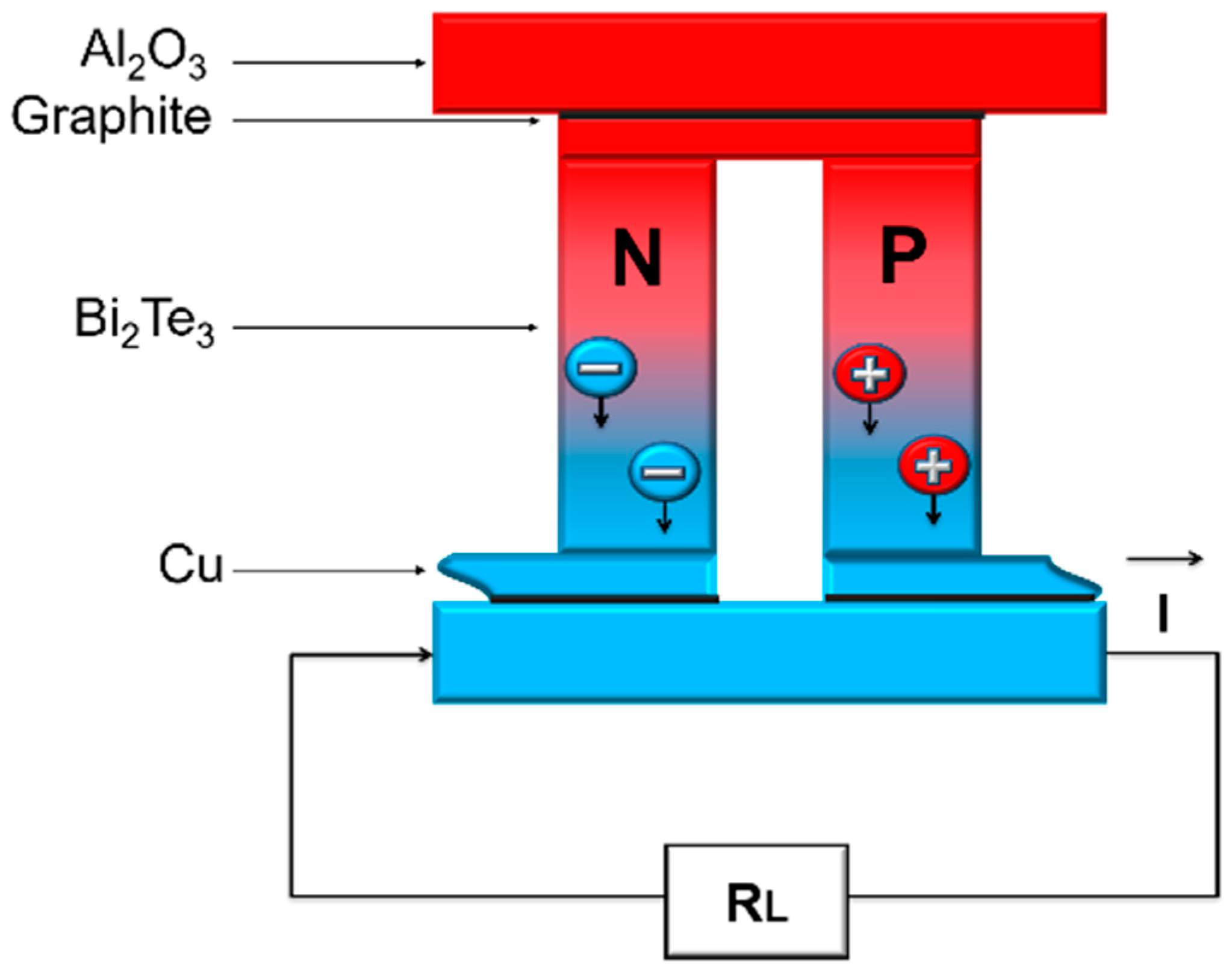
The results were calculated using the commercial thermoelectric module TEHP 1263-1.5 (Thermonamic) as reference. This device consists in 126 pairs of bismuth telluride legs, joined by copper strips, as shown in the thermoelectric pair of
Figure 1. The entire system is welded between two ceramic plates of 96% Al
2O
3, which contain a graphite film of high thermal conductivity, 0.127 mm thick, which is used to decrease the thermal contact resistance in the region.
The analytical model of the thermoelectric generator was carried out based on the classical theory of steady state analysis of electrical circuits, after studying thermoelectric effects and micro energy generation through energy harvesting. After that, a three-dimensional geometric model was developed for the numerical simulation, containing 28 pairs of bismuth telluride legs, whose set of equations were solved using Finite Element Method (FEM) of COMSOL Multiphysics
®. The results were extrapolated to the 126 pairs of the TEG used as reference.
Table 1 contains the dimensions used in the construction of the model.
2.1. Analytical Modeling
A mathematical model consists in the application of mathematical techniques and processes to make predictions, simulations, and testing conjectures. In this work, a mathematical approach is taken from the steady state system [
2,
21,
22], in order to determine the internal resistance of the commercial TEG, TEHP 1263-1.5 (Thermonamic), and to predict its power generation behavior.
The open circuit voltage (
Vopen) produced by the thermoelectric modulus is given by Equation (1), as a function of the Seebeck coefficient (
αpn), of the temperature difference (∆
T) between the upper and lower faces of the thermocouples and of the number of thermoelectric pairs (
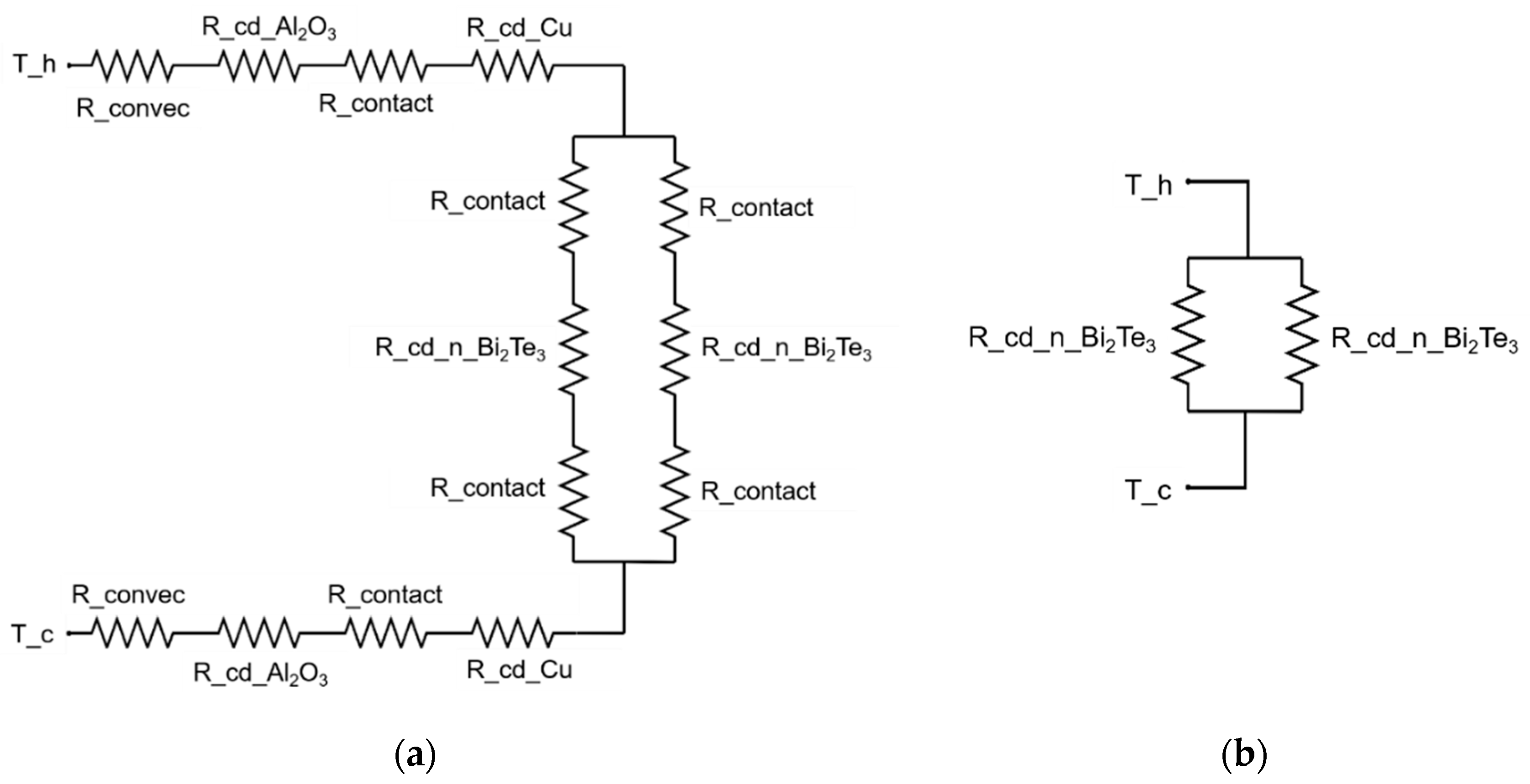
N). In this equation occurs the first simplification, where the known temperature values are those specified on the hot and cold faces of the ceramic. Therefore, because the ceramic is a good thermal conductor, the temperature at the external surface of the ceramic is considered to be the temperature at the respective joints, ignoring the heat transfer to the joints. The same consideration was made for the graphite film.
Figure 2 presents the thermal model of a thermoelectric pair before and after the simplifications.
Although the Seebeck coefficient varies with temperature, it was considered constant and equal to 200 µV/K [
23] for type
p, and of opposite value for type
n. The contribution of the copper (Cu) to the thermoelectric effect was neglected because the intermediate conductors law says that the contribution of a homogeneous conductor to the voltage is zero when its extremes are at the same temperature (5). The same is true for ceramics and the graphite film.
In a closed circuit, the Seebeck voltage is consumed by the load resistance (
RL), according to Equation (2).
The TEG electrical resistance (
Rint) can be calculated by Equation (3). Due to the fact that the pairs are electrically in series, the electric resistance of the converter is the sum of the resistances of the pairs. This equation neglects the four electrical contact resistances between the thermocouples and the copper.
Considering that the bismuth telluride legs have the same dimensions and thermoelectric properties, Equation (3) can be rewritten according to Equation (4). Also, the temperature dependence of the materials electrical resistivity (
ρ) was neglected in the analytical model. The electrical resistivity of copper is equal to 1.72·10
−8 Ω·m and [
24] of bismuth telluride is equal to 10 μΩ·m [
23].
The output power produced by the generator can be calculated using the values of resistance and voltage, considering that a constant temperature is maintained between the junctions, according to Equation (5). Likewise, the maximum output power occurs when the load resistance has the same value of the internal resistance (Equation (6)).
2.2. Numerical Analysis
For the numerical simulation, a three-dimensional geometric model representative of the commercial device TEHP 1263-1.5 (Thermonamic) had been constructed, with a differential strategy of containing only 28 pairs of bismuth telluride legs connected in series (4.5 times fewer legs than the actual device), thus reducing computational processing time. In addition, the highly conductive graphite thin film was neglected, due to its small size and scarce properties. In addition, its main influence was found in thermal contact resistances between ceramics, copper, and thermoelectric pairs, whose values were determined inductively from material datasheets, relating surface roughness, microhardness, contact pressure, and gap conductance.
The model was solved by the software where it was established (COMSOL Multiphysics®) by the finite elements method, whose principle resides in dividing the complex geometry of the problem into a limited number of smaller and simpler elements, connected by points denominated nodes and with this the method is able to approach a solution to the problem.
The geometric model was constructed using multiphysical packages of electric circuits and thermoelectric effect at steady state. As in the analytical model, it was assumed that the thermoelectric effect is only due to the bismuth telluride pairs, and that the legs have the same dimensions and thermoelectric properties. It is also considered that the temperature is equally distributed on the ceramic plates. Unlike the analytical model, in this case, the properties of the materials (electrical conductivity and Seebeck coefficient) vary with the temperature from the intrinsic data of the software used, and the thermal and electrical contact resistances were inserted in the model. The temperature dependent properties used in the numerical analysis can be expressed by the subsequent polynomial equations. Equation (7) is used to calculate the electrical resistivity of cooper, with the following parameters: reference temperature (
) equal to 20 °C, resistivity at the reference temperature (
) equal to 1.72·10
−8 Ω·m, and temperature coefficient (
α) equal to 0.00393 °C
−1 [
24]. Equations (8) and (9) are used to calculate electrical resistivity (
,
R2 equal to 0.9998) and Seebeck coefficient (
αp,
R2 equal to 0.9997) of bismuth telluride, and their interval of application is from 200 K to 400 K.
3. Results and Discussion
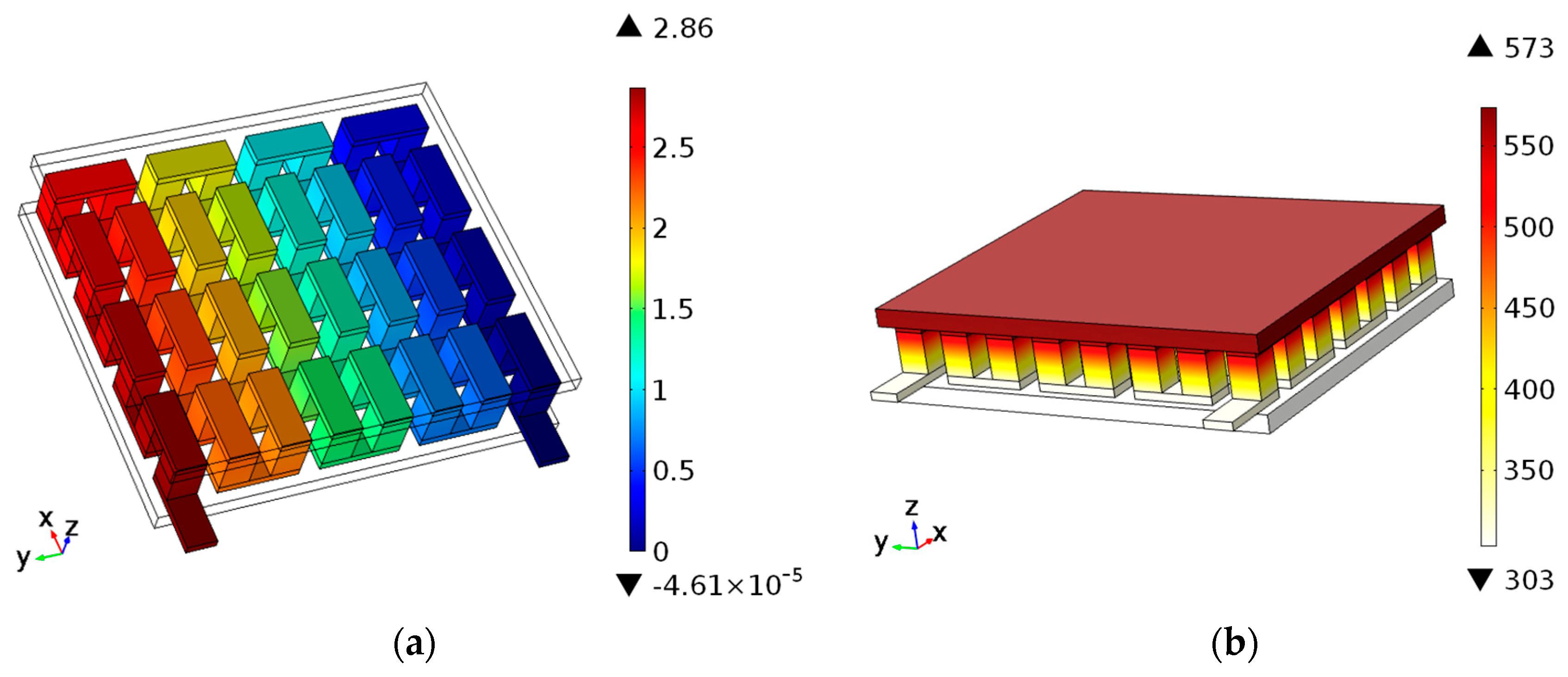
The result of the open circuit simulation (with
Tc equal to 30 °C and
Th equal to 300 °C) of the developed numerical model can be visualized in
Figure 3, demonstrating that the temperature gradient corresponds to a difference of electric potential.
The results were obtained using the dimensions of the commercial device [
20] and properties found in the literature. A charge of 2.96 Ω and a temperature gradient of 270 °C were considered, with the temperatures on the cold and hot faces being 30 °C and 300 ° C, respectively.
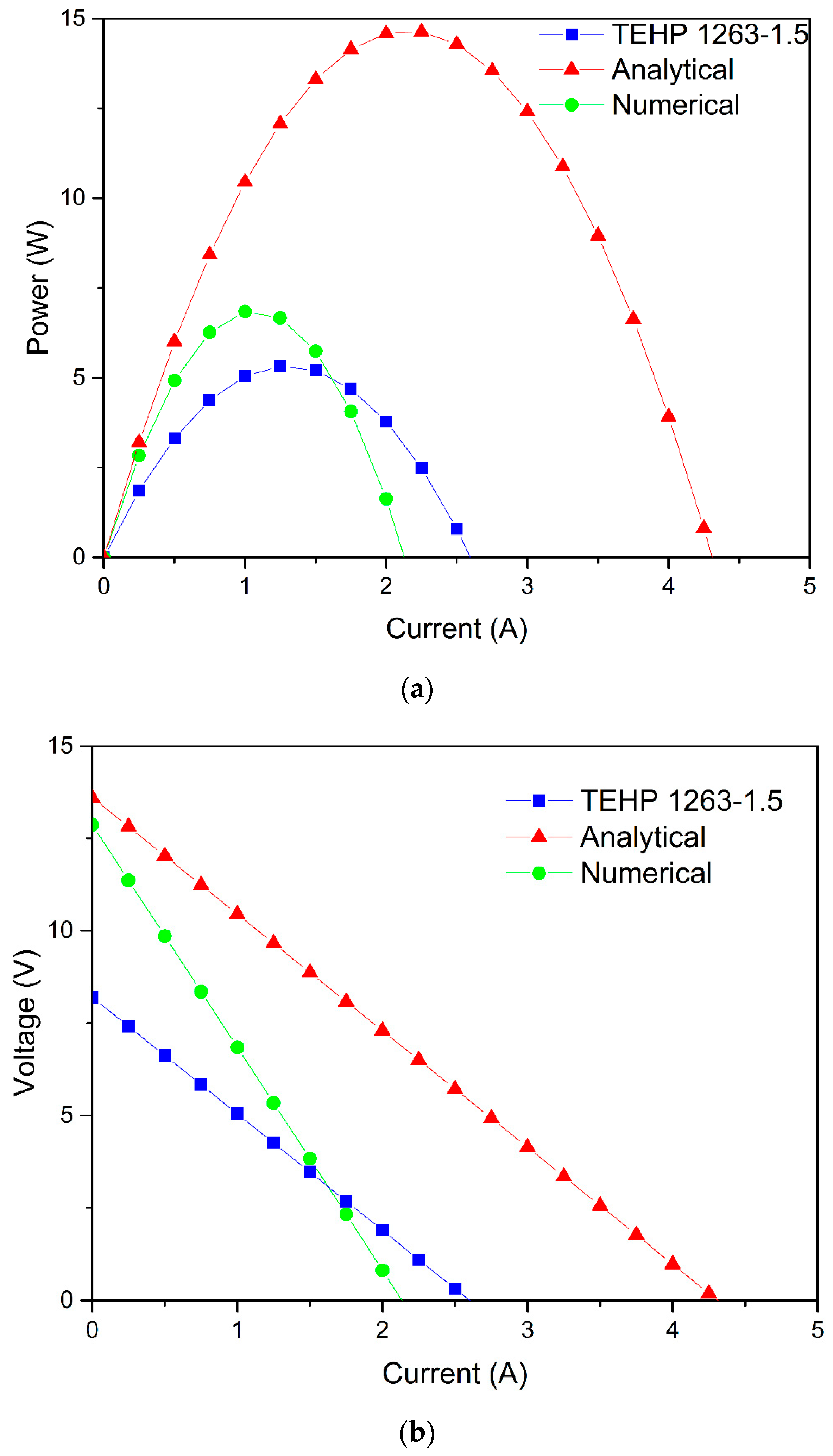
The internal resistance value of the module and the voltage, current, and power values were obtained for both the analytical and numerical models, which will be compared with the information provided by the fabricator, as observed in
Table 2. In addition,
Figure 4 shows the electric behavior of each model, according to the
Table 2.
It is observed in
Figure 4 that the calculated values of voltage, current, and power are higher than those of the manufacturer. This disparity is expected since the models are just a simplification of the actual device. For example, the consideration that both p-type and n-type bismuth telluride legs have the same electrical resistivity and thermoelectric properties. Although this is a simplification carried out in several works [
17,
25,
26], there are works that cite the differences between the properties of the materials [
27].
Besides that, in both analytical and numerical models, a homogeneous temperature distribution was assumed along with the faces. However, in real devices, this distribution is not always uniform and it is influenced by pressure. The pressure which the modules are subjected to in each step acts to increase the contact surfaces and, therefore, it influences the increase of the heat transfer. In addition, despite the fact that the heating of the air around the cold face, due to the natural convection which interferes in the overall efficiency, the convective effects were not taken into account because of the lack of information about the conditions which the module was tested by the manufacturer. Although there is insulation, it is reasonable to consider that the convection of direct air between the hot and cold faces impairs the heat dissipation through the thermoelectric module, causing a decrease in the temperature gradient. Indeed, a study by Bjork et al. [
28] said that heat losses due to convection inside the module were shown to be negligible for the module size considered in their work.
However, the analytical model presents a higher difference in current and output power values (
Figure 4a), as opposed to the numerical model (more complex than the analytical model), whose results are more approximated from the data of the manufacturer’s datasheet. This difference follows due to the simplifications made in the analytical equations that do not occur in the numerical model, from the simplifications already mentioned in the methodology until the calculation of the internal resistance. Also the temperature gradient was disregarded between the ceramic and the legs and it was considered the Seebeck coefficient constant. Nevertheless, the determinant factors for the high variation obtained are mostly due to the terms of the Equation (1). First, the external temperature of the faces instead of the temperature at the ends of the thermoelements was considered. Second the bismuth telluride properties according to the literature were used (Seebeck coefficient and electrical and thermal conductivities), since the production route of the material changes its properties [
29], and there are differences of properties between literatures [
17,
29,
30].
Moreover, in
Figure 4b the similarity between the slope of the curves allows analysis of the proximity of the real and analytically calculated values of the internal resistance, while the numerical model presented a larger slope, that is, a larger internal resistance as described in
Table 2. In addition, voltage versus current curves have a known fit equation (Equation (10)) in which the linear coefficient is represented by
Vopen, in other words, from
Figure 4b it can be inferred that the
Vopen calculation (Equation (1)) is highly responsible for the difference between the analytical and actual values of voltage and current, as well as output power, calculated by Equation (5).
Lv et al. [
31] used a similar analytical model to predict the output power of a TEG, obtaining a value 18.6% higher than the real value, while in the present work this value was 175.4% higher than the actual output power. However, the temperature difference was 44.1% lower than the used in this work, which is relevant since the higher the temperature gradient used, the greater are the errors added to the calculations, as evidenced by Orr et al., who presented a simplified analytical method to describe TEGs, in which output power and efficiency curves started to deviate at higher temperature gradients [
32].
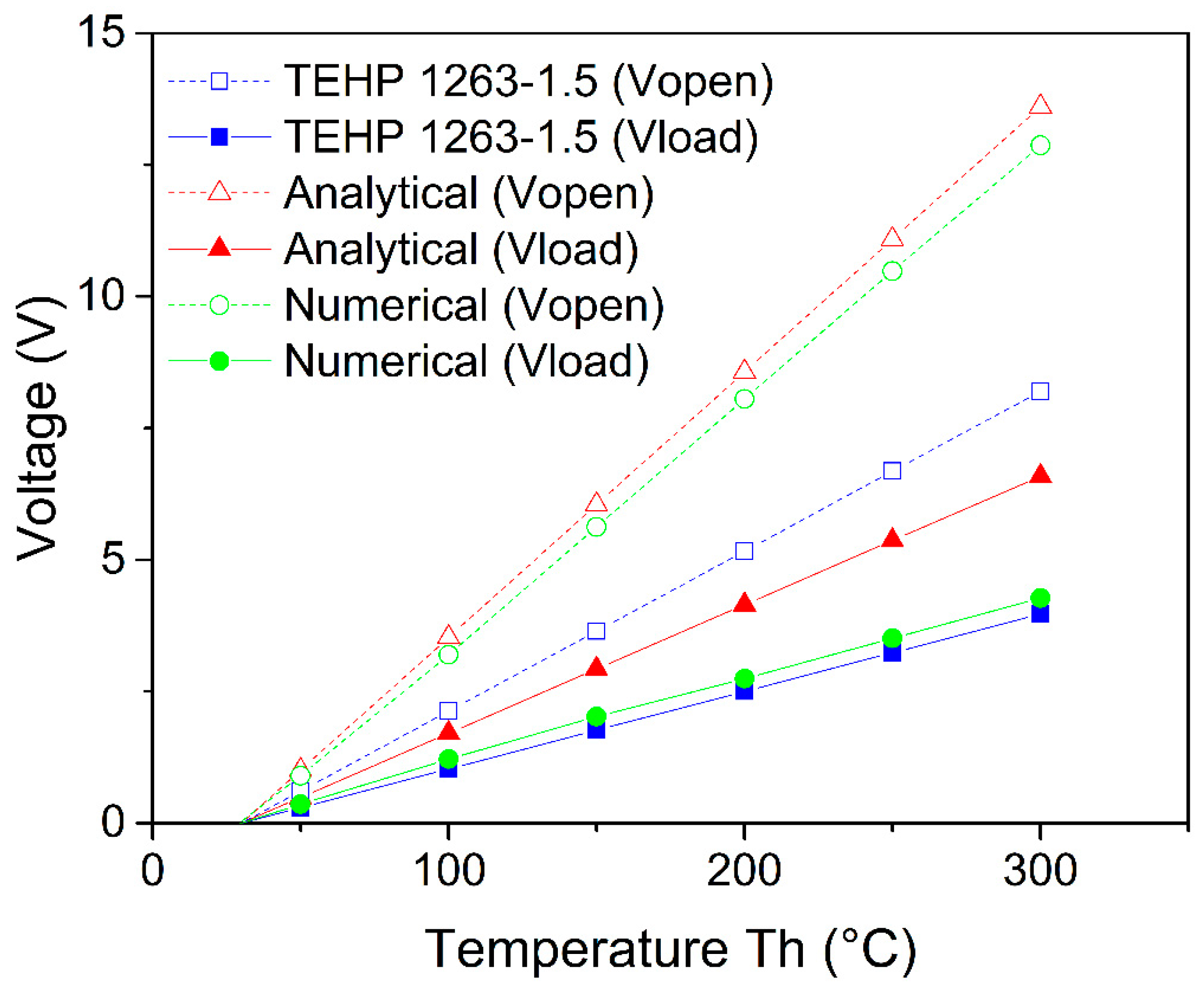
The results obtained in both the analytical and numerical models presented adequate behavior and similarity to the reference (
Figure 4).
Figure 5 highlights this comportment showing the comparison of the results obtained from open circuit voltage and charge voltage for each case and the voltage drop caused by the load resistance.
Although the results of voltage, current, and power of the numerical model were considered the best, the model that obtained the greatest result to estimate the internal resistance was the analytical model (
Table 2).
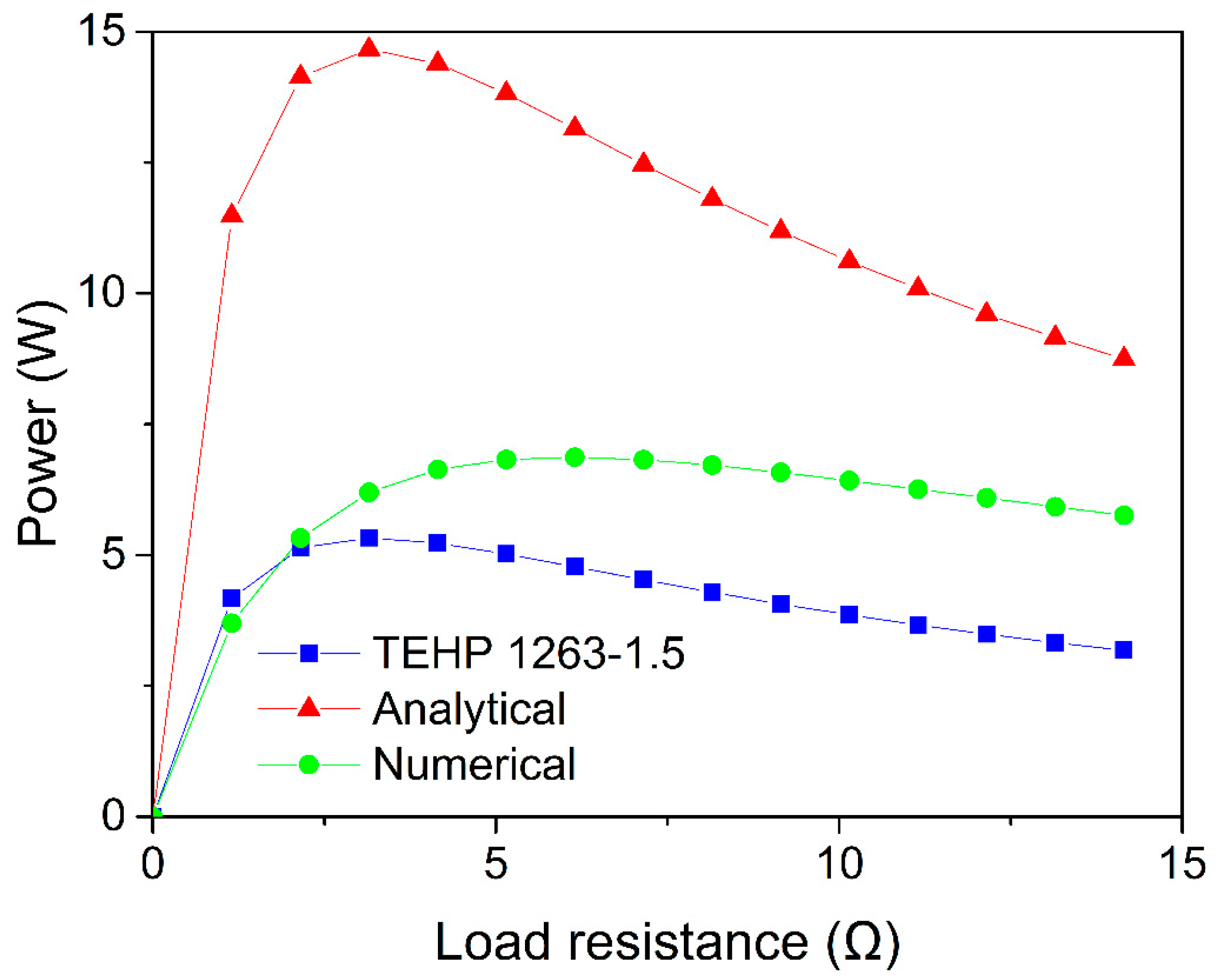
Figure 6 shows the optimum point, that is correspondent to the maximum output power, which occurs when the applied load resistance is equal to the internal resistance of the device. Thus, it is possible to analyze the increase in internal resistance by the displacing of the curve peaks to the right, with the numerical model being the farthest.
Therefore, the analytical method, in addition to being more simplified and requiring less quantity of tabulated data, resulted in the greatest approximation for the internal resistance. The simplifications that most influenced this calculation were the (i) contact resistances that were neglected, and (ii) use of average temperatures and constant thermoelectric properties, resulting in a lower internal resistance compared to the numerical model, in which the electrical contact resistances were considered. In addition, in cases where sophisticated software is not available, the proposed analytical model can be used to estimate the internal resistance, and if Vopen is experimentally obtained, the values of voltage, current, and power can be estimated with more accuracy by the analytical model.
With regard to the numerical model, the hypothesis is that the high value of internal resistance is related to the inaccuracy of some input data required by the software during calculation, such as the applied pressure that was not supplied by the manufacturer. Consequently, to fit the numerical model correctly it is necessary to carry out an in-depth survey of all the parameters required for the model.
It was observed in
Figure 6 that the output power decreases faster for load resistances that are smaller than the internal resistance, so it is preferred in practical systems to use a load resistance greater than the internal resistance. Therefore, despite the small discrepancy with the real value, the analytical model results in a good approximation of the internal resistance, besides being simple to calculate, and it does not require complex input data. The analytical model can be used as a guide to estimate the internal resistance of a thermoelectric module, allowing optimizing its use by choosing the load resistance that will result in an approximate value of the maximum output power. For example, when using a load resistance equal to 3.157 Ω, the power transferred by TEHP 1263-1.5 is 5.33 W, equal to the actual maximum output power.
It is worth mentioning that, despite knowing the approximate load resistance value that should be used to obtain the maximum power, the internal resistance of the TEG changes according to the temperature, thus changing the optimal value of load resistance. Since TEG is normally used to collect residual energies, it does not make sense to perform temperature control to stabilize the internal resistance. The correct action is to use a control system that corrects the load resistance according to disturbances in temperature. Studies have already been carried out to solve this problem, such as the one by Dalala [
33] who proposed two maximum power point tracking algorithms for controlling the load demand. Therefore, the analytic study presented in this work can be used to estimate the load resistance required to provide an approximated maximum output power from known temperatures.
4. Conclusions
This article presents the proposal of a mathematical approach with the development of an analytical model and a multiphysical numerical-computational model that allows estimation of the internal resistance and predicting the values of open circuit voltage, charge voltage, current, and power of TEGs. The predicted values of internal resistance, voltage, current, and power, and of a TEG were calculated from a simplified analytical model and a multiphysical numerical-computational model. The analytical model is the most indicated to calculate the internal resistance of the studied TEG, in the temperature interval between 30 °C to 300 °C. Rint (3.157 Ω) was obtained, almost equal to the real one (3.154 Ω) without using complex parameters such as in the numerical-computational model. Besides the values provided by literature, the entrance parameters consist just of measures of the TEG parts and of the temperatures at the hot and cold sides. On the other side, the numerical simulation showed greater results of voltage, current, and power than the analytical simulation, due to the higher number of simplifications performed in the analytical model. It is worth noting that besides the deviations in voltage, current, and power results, both models presented coherent behavior of these electrical variables.
Finally, due to the predicted internal resistance being greater than the actual internal resistance, the analytical model can be used as a guide to estimate the internal resistance of the TEG in the proposed temperature range, in order to correct the load resistance and to aim for the maximum system output power. Besides that, the numerical model is the most indicated to predict voltage, current, and output power values of the TEG.


