Thermal Performance of a PCM-Based Thermal Energy Storage with Metal Foam Enhancement

1
School of Mechatronics Engineering, Harbin Institute of Technology, 92, West Dazhi Street, Harbin 150001, China
2
School of Energy Science and Engineering, Harbin Institute of Technology, 92, West Dazhi Street, Harbin 150001, China
3
Key Laboratory of Aerospace Thermophysics of MIIT, Harbin Institute of Technology, 92, West Dazhi Street, Harbin 150001, China
*
Author to whom correspondence should be addressed.
Energies 2019, 12(17), 3275; https://0-doi-org.brum.beds.ac.uk/10.3390/en12173275
Submission received: 4 July 2019
/
Revised: 12 August 2019
/
Accepted: 20 August 2019
/
Published: 26 August 2019
(This article belongs to the Section D: Energy Storage and Application)
Abstract
:The energy transport inside a phase change material (PCM) based thermal energy storage system using metal foam as an enhancement technique is investigated numerically. The paraffin is used as the PCM and water as the heat transfer fluid (HTF). The transient heat transfer during the charging and discharging processes is solved, based on the volume averaged conservation equations. The flow in PCM/foam and HTF/foam composites is modelled by the Forchheimer-extended Darcy equation, while the two-temperature model is employed to account for the local thermal non-equilibrium effect between the foam matrix and fluid phase. The results show that the overall performance is greatly improved by inserting metal foam in both HTF and PCM sides. A nearly 84.9% decrease in the time needed for the total process is found compared with the case of pure PCM, and 40% compared with the case of metal foam insert only in the PCM side. Foam porosity and HTF inlet temperature greatly affect the dynamic heat storage/release process.
1. Introduction
Thermal energy storage (TES) using the latent heat of phase change material (PCM) has be used nowadays in numerous applications and attracted considerable attention [1]. The latent TES exhibits an isothermal storage/release process, and holds several advantages, such as high energy storage density, relatively mature technology, and availability in wide temperature range [2]. This makes the latent TES very promising for energy collection and reuse, which is beneficial to energy conservation and emission reduction. Consequently, it can be found in many industrial fields, like concentrating solar power plants, waste heat recovery, temperature regulation of buildings, compact heat exchangers, thermal management of electric devices, etc. [3,4,5]. However, the key disadvantage of PCM is its intrinsically low thermal conductivity, which limits the heat transfer rate during the charging and discharging cycles. Therefore, improving the PCM thermal conductivity has become a hot topic in this research area.
The approaches to fulfill the above objective fall into three levels summarized by Zhao et al. [6]: material level, such as addition of highly thermal conductive particles and infiltrating the PCM into the porous matrix; component level, such as adding fins, using enhanced heat transfer tube and macro-capsulation; and system level, such as adopting cascaded latent heat storage. Among these approaches, the use of highly porous foam is an effective method which has been outlined by many scholars in recent years. Extensive works have been carried out to explore the effectiveness of performance improvement using porous foam, involving the thermal conductivity enhancement, phase change enhancement, thermal storage unit enhancement, etc. [7], from fabrication, characterization, and mathematical modeling to application [8]. Compared with pure PCM, an improvement of 3–500 times can be achieved using metallic and carbon-based porous material/foam according to the review by Tauseef-ur-Rehman et al. [3]. Zhao et al. [9] experimentally found that inclusion of metal foam increases the overall heat transfer rate up to 10 times, compared with pure paraffin. By embedding copper foam, Cui [10] observed that the heat transfer rate is enhanced by 36% compared with pure PCM. Lafdi et al. [11] experimentally observed that the phase change heat transfer within the PCM/foam composite is significantly affected by the foam porosity and pore size.
The latent TES unit, as a part of the PCM-based heat exchanger in the practical applications, is usually a shell-tube or rectangular type. The heat transfer fluid (HTF) and PCM occupy two channels separated by a solid wall, and the heat transfers from HTF to PCM during the charging process, while the opposite occurs during the discharging process. The previous works mainly focus on the technologies to reduce the thermal resistance in the PCM side to accelerate the heat transfer rate, while that in the HTF side is rarely considered. Metal foam is usually added in the PCM side to ameliorate the phase change heat transfer. The impact of foam porosity on a latent heat TES device was analyzed by Atal et al. [12], they found that smaller porosities could shorten the melting–freezing cycle. Martinelli et al. [13] conducted an experimental study on a TES system with a copper foam insert in the PCM, the performances of vertical and horizontal configurations, and bottom and top injections were compared, respectively. The shell-and-tube TES unit was experimentally investigated by Yang et al. [14], they showed that completely melting the metal foam/PCM composite takes over 1/3 less time than that of pure paraffin. In addition to the experimental studies, numerical simulations are also executed for the parametric study and performance optimization of PCM-based heat exchanger. The volume-averaged theory is intensely adopted for the PCM/foam zone. Additionally, the prior studies mostly simplify the physical problem, only considering the cross-section of the TES unit using a 2D computational domain. Mahdi and Nsofor [15,16] investigated the heat transfer characteristics inside a triplex-tube PCM TES system during the melting and solidification, with a compound porous-foam/nanoparticles enhancement technique. Phase change within a double pipe heat exchanger is modelled by Taghilou et al. [17] under time-dependent boundary conditions. Pourakabar and Rabienataj Darzi [18] discussed the effects of shell shape, arrangement of inner tubes and metal foam insert on the performance of a TES system. They pointed out that melting and solidification rates can be both increased by inserting metal foam.
Considering that the HTF/PCM temperature changes along the flow direction in an actual situation during the charging and discharging processes, a comprehensive model involving the flow and heat transfer both in the HTF and PCM sides should be built [2,19,20,21,22]. Liu et al. [19] developed a numerical model including the convective heat transfer of HTF and the melting process of PCM within metal foam. The melting and solidification processes of PCM embedded in metallic foam within a multi-tube heat exchanger were investigated by Esapour et al. [20], implementing a 3D simulation. It was found that melting time is decreased by 14% and 55% using the foam porosities of 0.9 and 0.7, respectively. A combination of surface waviness and porous medium was introduced by Shahsavar et al. [21] into the double-pipe latent heat storage system, and the feasibility in decreasing the melting/solidification time was demonstrated, based on thermal equilibrium thermal model. Extra addition of metal foam into the HTF domain was first proposed by Yang et al. [2], and it presented better performance in the melting charging process. Kumar and Saha [22] modelled a latent TES unit with variable porosity metal matrix and found that the size of the TES system can be reduced for the same energy efficiency.
The existing researches mostly focus on the heat transfer in the PCM zone within the TES system, hardly considering the thermal resistance of heat transport from or to the HTF. The longitudinal variation of HTF/PCM temperature is also scarcely taken into account. Furthermore, the charging and discharging processes are usually individually investigated, and many numerical works initialize the PCM as a uniform temperature during the release process, which may cause a different initial condition from the real situation. In this study, a comprehensive numerical model for the TES unit with HTF and PCM zones both filled with metal foam is established, including the local thermal non-equilibrium effect, coupled heat transfer in the HTF/foam-solid wall-PCM/foam system, and phase change in PCM. A complete process of charging and discharging is directly simulated, using the totally melting state as the initial condition for discharging. The dynamic temperature and liquid fraction, time needed in the whole process are obtained under different operating conditions.
2. Physical Problem Description
As shown in Figure 1, the PCM-based TES system is composed of several parallel plates occupied by HTF and PCM which are respectively water and paraffin, similar as the configuration in [23]. Both of the two regions are filled with metal foam to intensify the heat transfer. The TES system is vertically arranged, and the water flow is injected from the top side. Due to its symmetry relationships, the basic unit is considered as the computational domain (dotted domain in the figure). The widths of flow channel and PCM container are, respectively, mm and mm, while the thickness of the solid wall composed of the stainless steel is mm. The total length of the channel and container is mm.
The numerical model is created under the following assumptions: (1) the water flow and liquid PCM flow are assumed to be laminar and incompressible, (2) the metal foam is considered homogeneous and isotropic, (3) the volume expansion of the PCM during phase change is neglected [2,17,18,21], (4) the Boussinesq approximation is used to account for the natural convection inside the PCM, and (5) the thermo-physical properties are constant. Based on the above assumptions, the governing equations can be expressed as:
The thermal resistance of the interface solid wall with a finite thickness is considered, and the control equation of the thermal conduction is given as:
The heat exchange between the HTF and PCM sides are coupled through the solid wall. The continuity of temperature and heat flux at the interfacial wall surface should be guaranteed, the following boundary relations are adopted [26,27].
Wall surface at the HTF side:
Wall surface at the PCM side:
Subscripts f, p, s, and w respectively refer to the water flow, PCM, metal foam, and the solid wall; , c, , , and represent the density, specific heat, dynamic viscosity, effective thermal conductivity, and thermal expansion coefficient, respectively; ϕ, , , , are the porosity, specific surface area, interstitial heat transfer coefficient, permeability, and inertial coefficient for the metal foam; is the liquid fraction of PCM in the porous medium, where is the liquid fraction in the pore space. The melting and solidification model in the ANSYS FLUENT (Canonsburg, Pennsylvania, USA) is used to solve the phase change process. Besides, the phase change of paraffin takes place over a range of temperature. Enthalpy-porosity method is adopted, and the liquid-solid mushy zone is treated as a pseudo porous zone. The variable is determined by the following formulas [17,18,21]:
Here, and are the solidus and liquidus temperatures of PCM, which are 321 K and 335 K, as listed in Table 1. The term relates to the pressure drop due to the effect of phase change, and ζ are two numerical constants with values of 105 and 0.001; is reference temperature, the variables , T, p separately denote the velocity, temperature and pressure; is the latent heat of PCM, and τ is the process time.
Porosity ϕ and pore density are two main parameters used to characterize the foam structure, and the other like the permeability and the inertial coefficient are calculated from the formulations proposed by Calmidi and Mahajan [28]:
where is the ligament diameter of metal foam which can be computed as:
where the pore diameter is .
The effective thermal conductivities of the solid and fluid phases are calculated with the following equations proposed by Boomsma and Poulikakos [29]:
where:
The interfacial heat-transfer coefficient between the metallic foam and the PCM/HTF is estimated using a commonly-used empirical model suggested in several studies [2,20,25]:
where the Reynolds number is , and the specific surface area of the metallic foams is computed as:
The transport parameters in Equations (7)–(9) for the PCM/foam composite can be similarly obtained based on the above correlations. The thermo-physical properties of paraffin, copper foam, stainless steel, and water are listed in Table 1. The initial temperature of the storage system is 300 K. The water flow is injected from top with uniform velocity of 0.05 m/s, temperature of 350 K for the charging process and 300 K for the discharging process. The outflow boundary condition is applied to the outlet. The top and bottom surfaces of the PCM container is insulated, and the other two sides of unit are specified as symmetry. The porosity of copper foam is 0.9 and the pore density is 10 PPI. The transition of charging and discharging processes during the simulation is the time instant when the whole PCM is just totally melted (γ = 1), the condition at the end of melting is used to initialize the discharging process. This is the same operating mode as the actual situation. The time is recorded until the PCM is just totally solidified (γ = 0) during the discharging process.
3. Numerical Model Validation
The above governing equations are solved by the commercial software ANSYS FLUENT (Canonsburg, Pennsylvania, USA). The solidification/melting module is selected to solve the phase change process in the PCM. The SIMPLE (Semi-Implicit Method for Pressure Linked Equations) algorithm is adopted for pressure-velocity coupling and the PRESTO (PREssure STaggering Option) scheme for the pressure discretization is used. The second order upwind scheme is implemented to discretize the convective terms, and the QUICK (Quadratic Upwind Interpolation of Convective Kinematics) scheme is applied for energy equations. Residual convergence values for continuity, momentum, and energy are set to 10−6, 10−6, and 10−9, respectively. Several user defined functions (UDFs) are programed to determine the transport parameters, such as thermal conductivity, interfacial heat-transfer coefficient, etc. After the independent check, a grid arrangement of 200 × 65 and time step of 0.5 s are used for a compromise between the accuracy and the computational time.
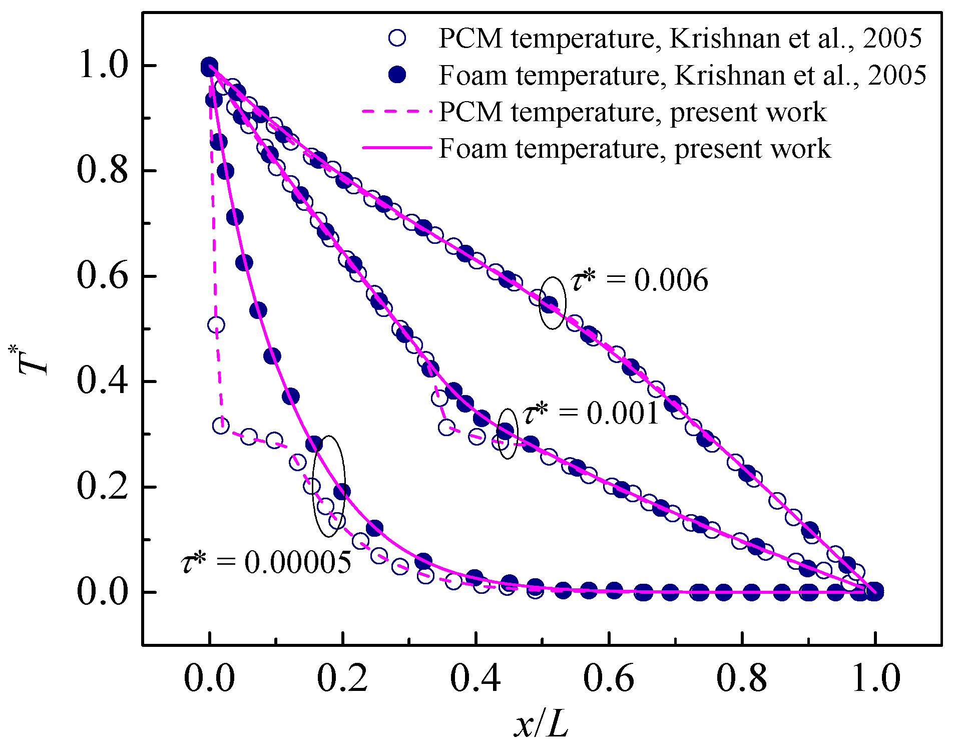
To verify the numerical simulation, the melting process of a PCM/foam composite within a closure (length to height is L/H = 1.0) is firstly modelled, employing the two-temperature model and considering the natural convection. The main parameters are ϕ = 0.8, , , , where the Th and Tc are the two wall temperatures. Further details about the model are available in Krishnan et al. [30]. The temperature profile versus time at the mid-height of domain is compared with the numerical results from [30] in Figure 2. It can be seen that a good agreement is presented.
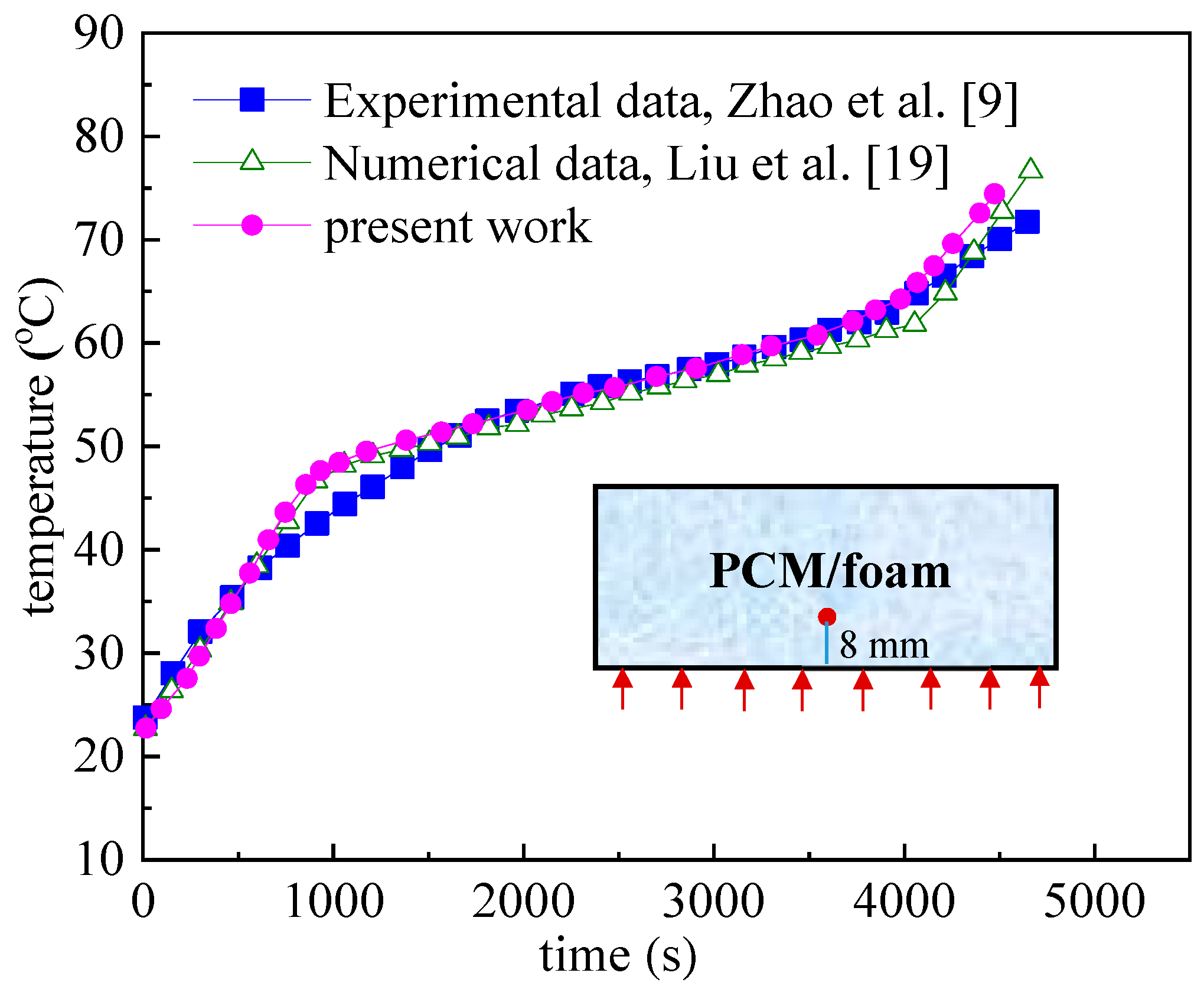
The melting process of cooper foam/PCM composite in a rectangular closure with the porosity of 0.95 and pore density of 10 PPI is also simulated. The sample is heated on the bottom wall with a constant heat flux. The temperature of a point (8 mm above the bottom side) is recorded. The experimental data from Zhao et al. [9] and numerical data by Liu et al. [19] are compared here, which shows a good agreement as presented in Figure 3.
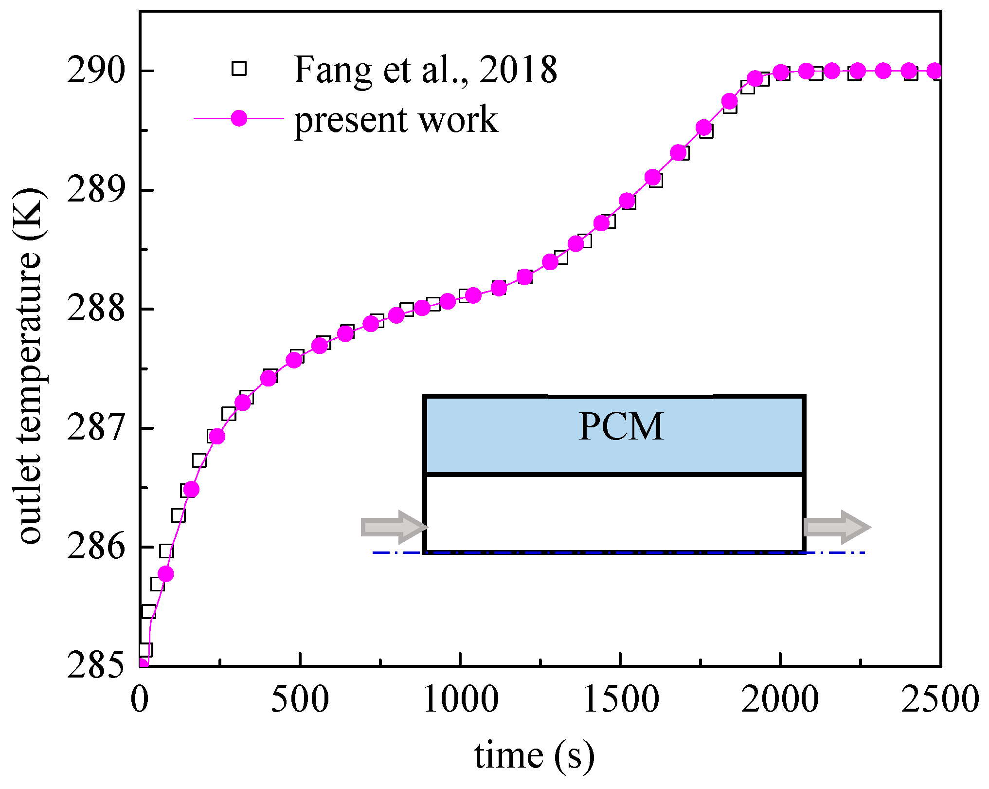
The third validation case is simulating the charging process of a PCM-water heat exchanger without foam insert [31]. The total length is 6 m with an inner tube diameter of 5 mm and an outer tube diameter of 10 mm. The outlet temperature of water changing with time is plotted in Figure 4. As can be seen from the figure, the predicted temperature response matches well with the numerical results from the literature.
4. Results and Discussion
4.1. Enhancement Performance of Metal Foam
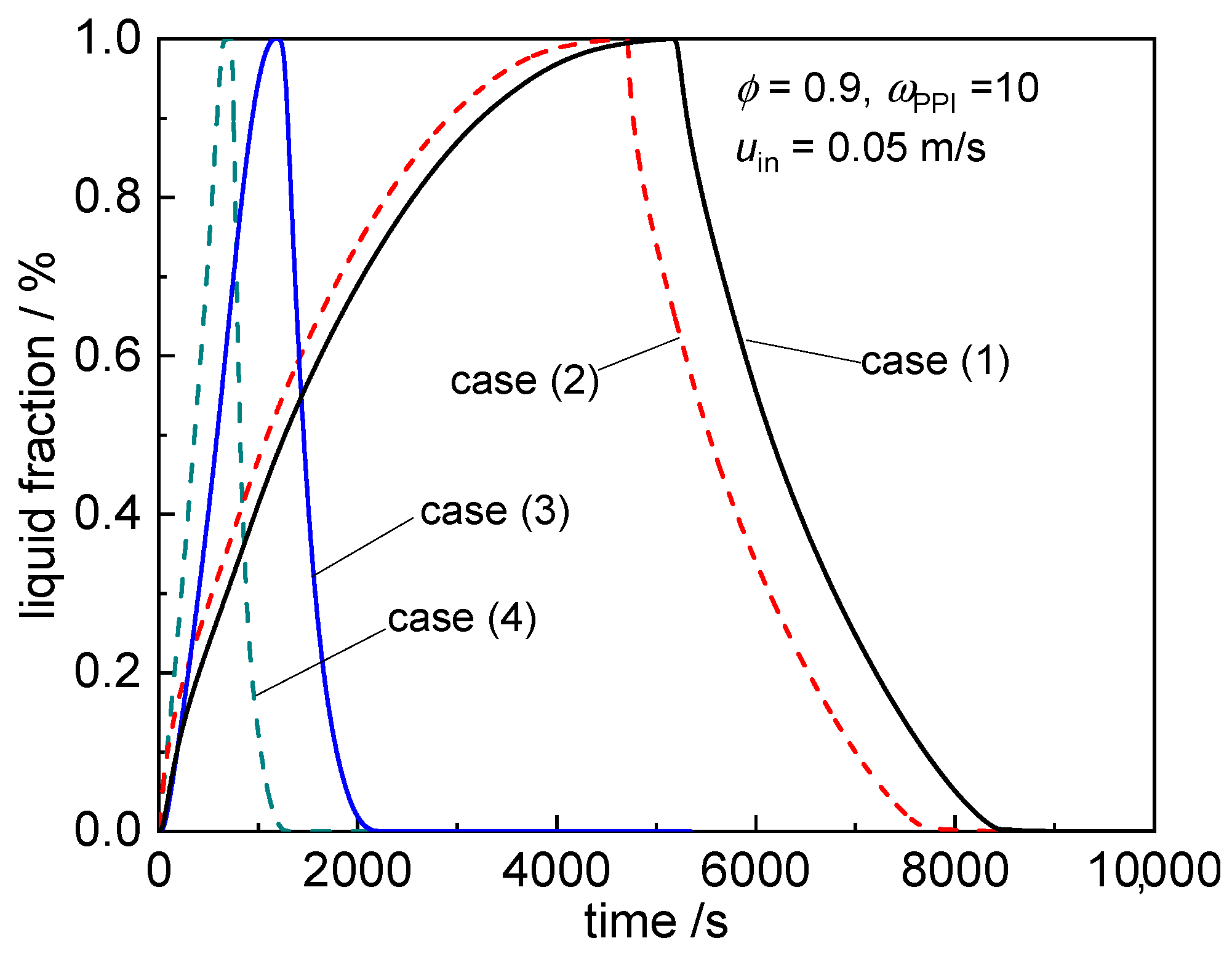
In order to explore the enhancement effects of metal foam insert on the heat transfer efficiency of the PCM based TES system, the location arrangement of metal foam is firstly discussed using four cases, which are (1) no foam insert, (2) foam insert in the HTF side, (3) foam insert in the PCM side, and (4) foam insert in both the HTF and PCM sides. Notice that the dimension of PCM container should be adjusted to keep the same mass of PCM, consequently leading to the same storage capacity of PCM. The length and other size parameters are fixed.
Figure 5 shows the change of liquid fraction during the charging and discharging processes, and the times needed for each are listed in Table 2. Here, the total recorded time is from the initial state to the time of complete solidification (γ = 0).
Since the initial temperature is lower than the phase change temperature, the melting process has two stages, the sensible heat storage and the latent heat storage. In the early short time, the whole PCM remains in the solid state, the conduction dominates the heat transfer. As more heat is transferred from the hot HTF to the PCM side, PCM begins to melt when it reaches the phase change temperature. The convection will become the key role due to the buoyancy effect. When the PCM is just totally melted (γ = 1), the time is recorded for the melting process. Then, the cold HTF is injected into the system for the discharging process. It can be found that the liquid fraction decreases very quickly. Generally, the change in liquid fraction is steeper in the discharging process than the charging process as shown in the figure. The sensible heat and latent heat are also released during the discharging process. The time when the PCM is totally solidified (γ = 0) is recorded for the discharging process. Additionally, it can be seen from Table 2 that the latter one of the two processes has a shorter time.
The total time is 9012.0 s, 8412.5 s, 2266.0 s, and 1362.0 s for the four cases, respectively. Using case (1) as the basis, the total time is significantly decreased (nearly 74.9%) by adding metal foam in the PCM (case (3), which means that metal foam insert has greatly decreased the thermal resistance in the PCM side. Besides, the insert of metal foam within the HTF (case (2) also has an improvement in heat transfer compared to case (1), due to that more heat can be obtained from HTF and transferred to PCM with the help of volumetric heat exchange in foam structure. The improvement is nearly 6.6%, which is not obvious due to the comparatively high thermal conductivity of HTF (water). Case (4) takes the least time for the whole process, the total time is apparently shortened, about 84.9% less than case (1). Furthermore, compared with case (3), the extra insert of metal foam in the HTF side can further decrease the total time by about 40.0%, which shows the effectiveness of metal foam insert both in the HTF and PCM sides.
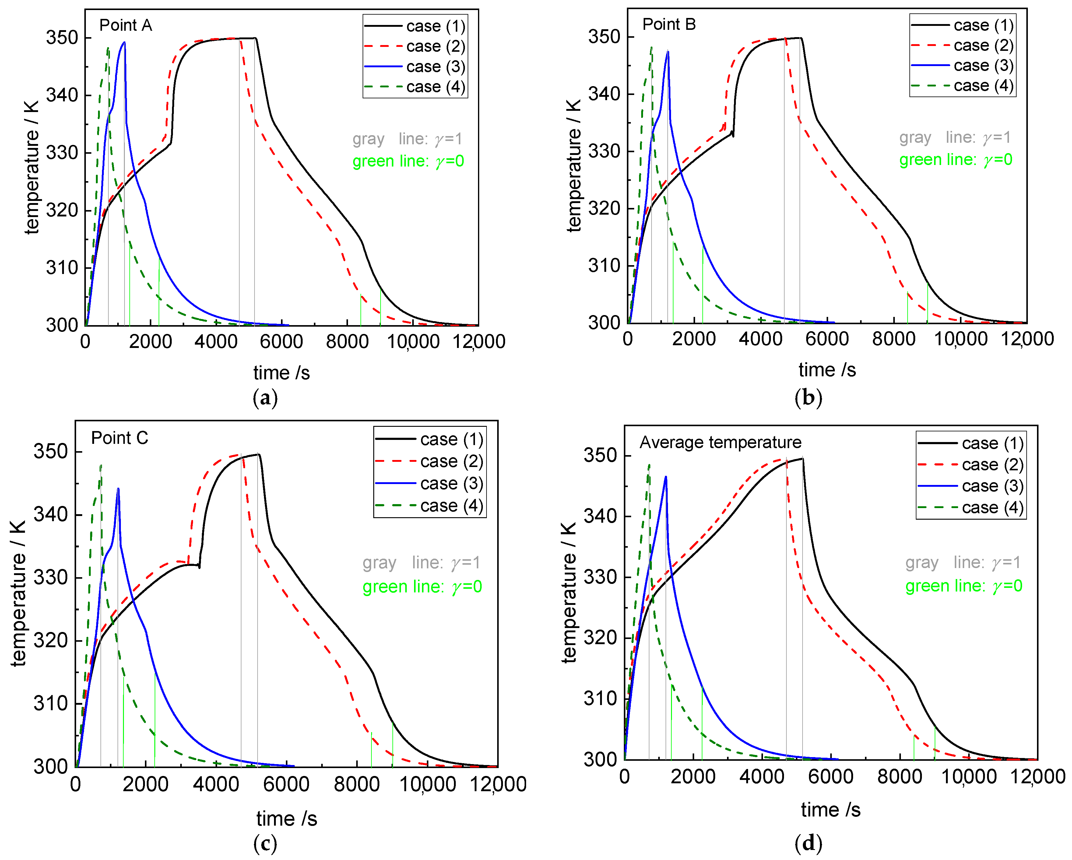
Figure 6 presents the temperature variation of three points and the change of PCM average temperature. The point locations are A (0.025, 0.1), B (0.025, 0.2), and C (0.025, 0.3). For each case, the temperature change trend of the three points is similar. For each point location, the temperature changes more dramatically in cases (3) and (4) than that in cases (1) and (2), which is due to the enhancement of heat transfer by the porous structure within the PCM side. Temperature variations in cases (1) and (2) are similar, so are those in the other two cases.
During the discharging process, until the PCM is completely solidified (γ = 0), the ultimate temperature is a little higher (about 10 K) in the cases (3) and (4). The reason is that inserting metal foam leads to a flat temperature gradient. In the discharging process, the stored heat in PCM is released and transferred to HTF, the temperature decreases. With the heat transfer enhancement, the PCM average temperature is higher as shown in Figure 6d. The metal foam augments the heat transfer, and the PCM temperature globally reduces toward the HTF temperature. Consequently, PCM temperature remains relatively higher, while the temperature at all the locations reaches values below the melting point. On the other hand, for cases (1) and (2), the region near the solid wall firstly solidifies. There exists obvious temperature difference in the PCM side. The heat slowly transfers from the outer PCM to the HTF through this near-wall region. The ultimate overall temperature become relatively low until the total solidification, as shown in Figure 6d.
In the next sections, different influential factors are examined and discussed, such as foam porosity, inlet HTF conditions and its injection side. For easy comparison, the time consumption is summarized in Table 3.
4.2. Effect of Foam Porosity
In this section, two cases are considered: one is constant PCM mass and the other is constant TES volume (also the volume of PCM container). For the former case, the width of PCM container in Figure 1 should be adjusted according to the used porosity, in order to keep the same PCM mass in the simulation. Here, the condition of foam porosity of 0.9 is used as basis.
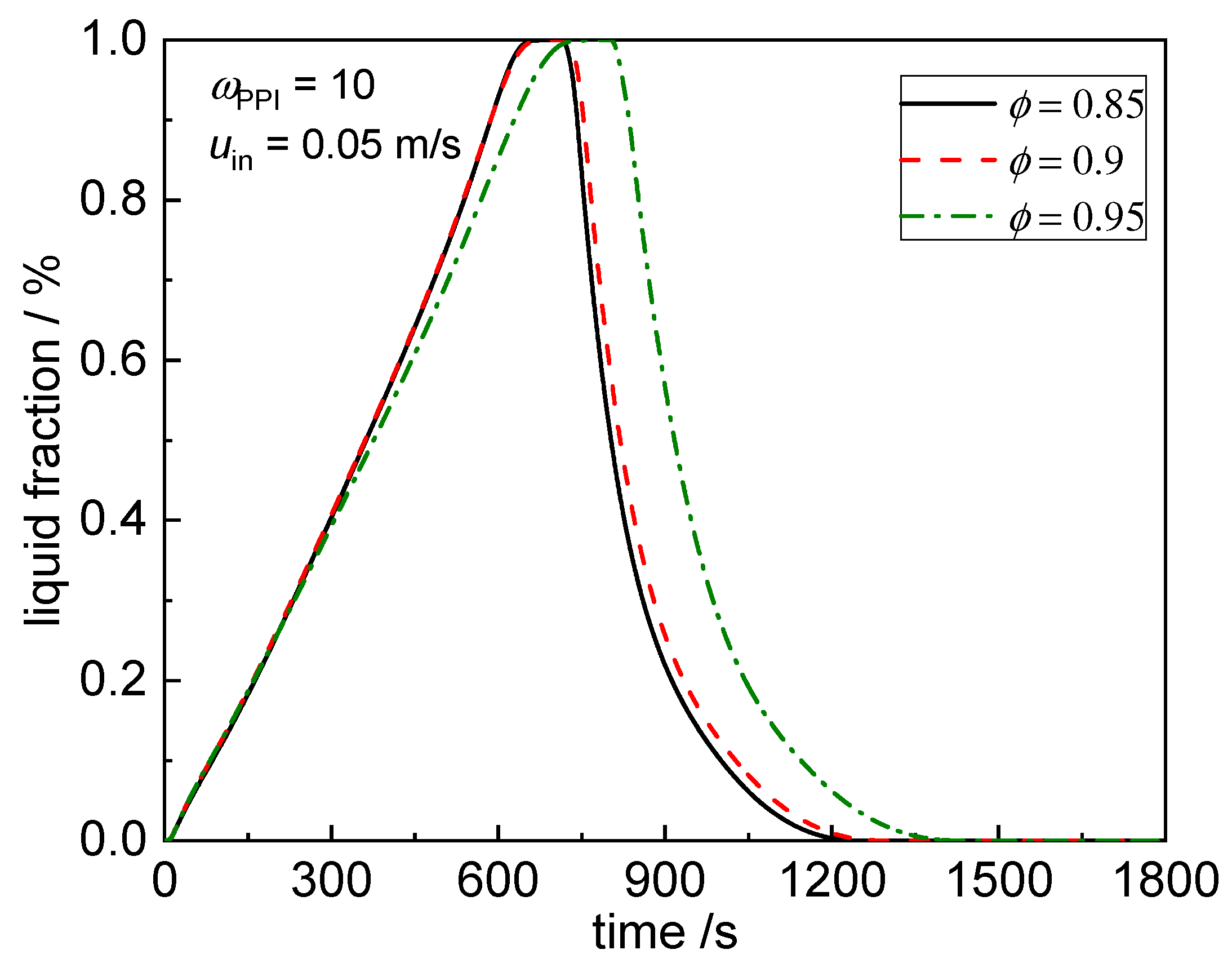
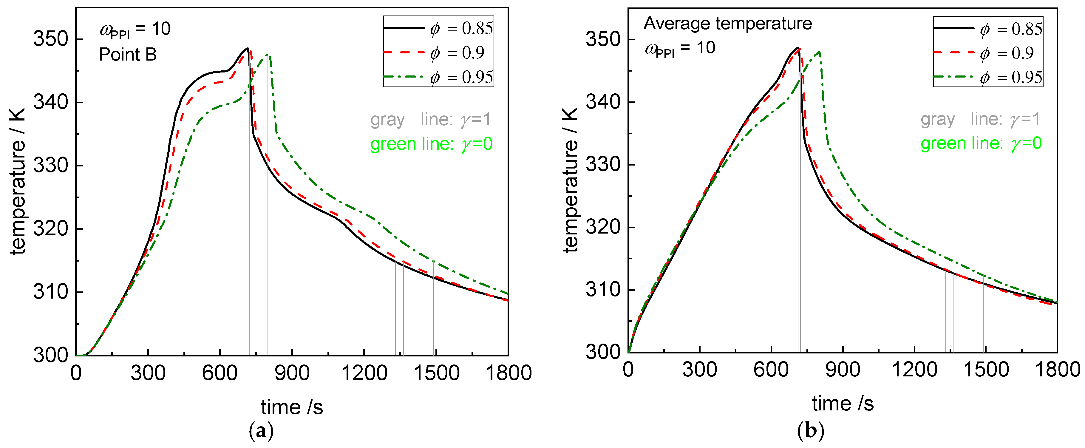
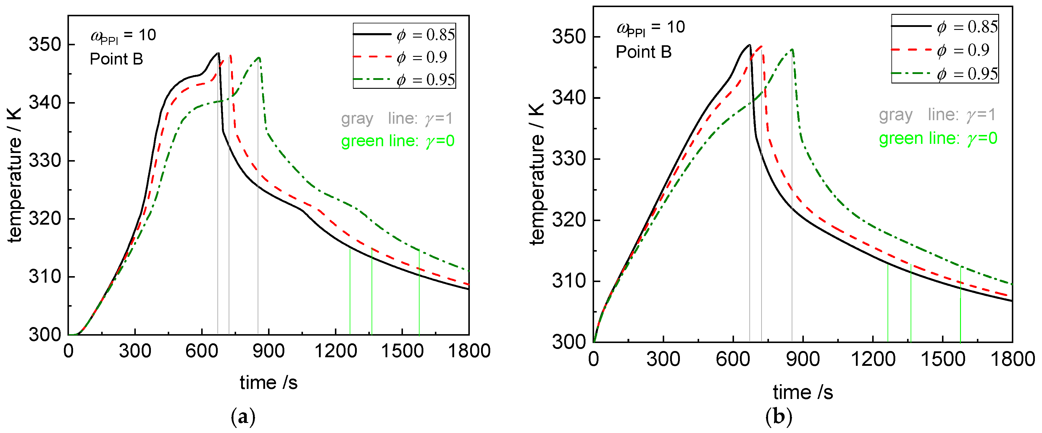
For the case at fixed PCM mass, Figure 7 exhibits the liquid fraction during the charging/discharging process at different foam porosities (ϕ = 0.85, 0.9, 0.95) with the pore density at 10 PPI. The other parameters are kept the same as the previous simulation. As the foam porosity decreases, the width of PCM container should be enlarged in order to keep the same PCM mass. From Figure 7, it can been seen that it takes more time for the charging/discharging process at a higher porosity. Besides, the change of liquid fraction has no great difference between the porosities of 0.85 and 0.9, it can be attributed to the increment in the dimension of PCM container and the contradiction between the effective thermal conductivity augmentation and the natural convection restriction. In general, lower porosity has a higher heat transfer rate, and the temperature varies more quickly, as depicted in Figure 8.
Furthermore, the temperature increases rapidly in the melting process, as shown in Figure 8. The variation trend is different from that in the case of no foam insert in the PCM side. Among the melting temperature range, no obvious change of slope occurs. The reason might be that the heat is quickly absorbed by the metal foam matrix firstly, and the matrix maintains at a high temperature which can provide sufficient heat to PCM for the latent storage and keep the PCM temperature at a gradual rise. From the temperature profile, the change of slope happens around 340 K. Comparing the Figure 7 with Figure 8, it can be found that all the PCM are nearly melted (as the liquid fraction is nearly greater than 0.95) at the time instant. The liquid PCM continuously absorbs heat and stores as sensible form. Notice that the convection also intensify the heat transfer in the liquid PCM. Consequently, the temperature has an obvious increase.
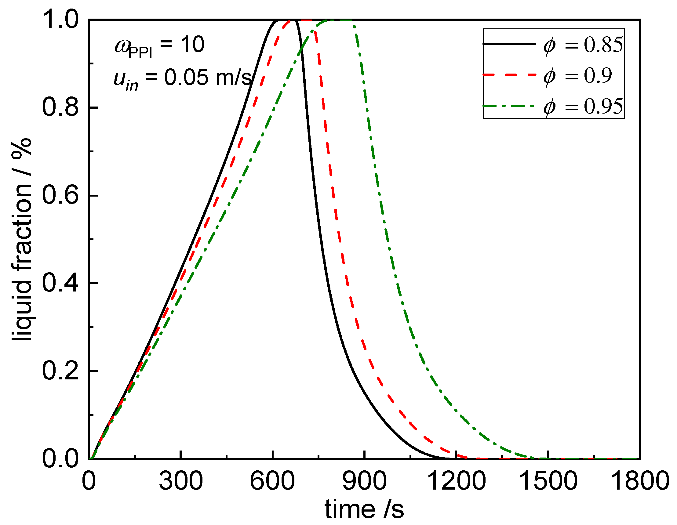
For the case at fixed TES volume, liquid fraction variation is presented in Figure 9 for the three porosities. The results clearly demonstrate that as the porosity decreases, the total time reduces noticeably, it can be attributed to a higher effective thermal conductivity and less PCM mass because of lower pore volume in metal foam. The melting/solidification rate increases with the decrement of foam porosity. The total time decreases from 1577.0 s to 1264.0 s (nearly 19.8%), as the porosity reduces from 0.95 to 0.85. Another main factor concerned is the natural convection, which although is restricted by lower porosity because of flow resistance in the movement of liquid PCM. This impact is not sufficient to have priority over the enhancement degree in the thermal conduction. The improvement of heat diffusion is more prominent in the PCM system. A lower porosity means a fast phase change process, which is also reflected by the temperature variation history, as shown in Figure 10. The temperature varies more rapidly for a lower porosity.
4.3. Effects of Inlet Conditions and Injection Side
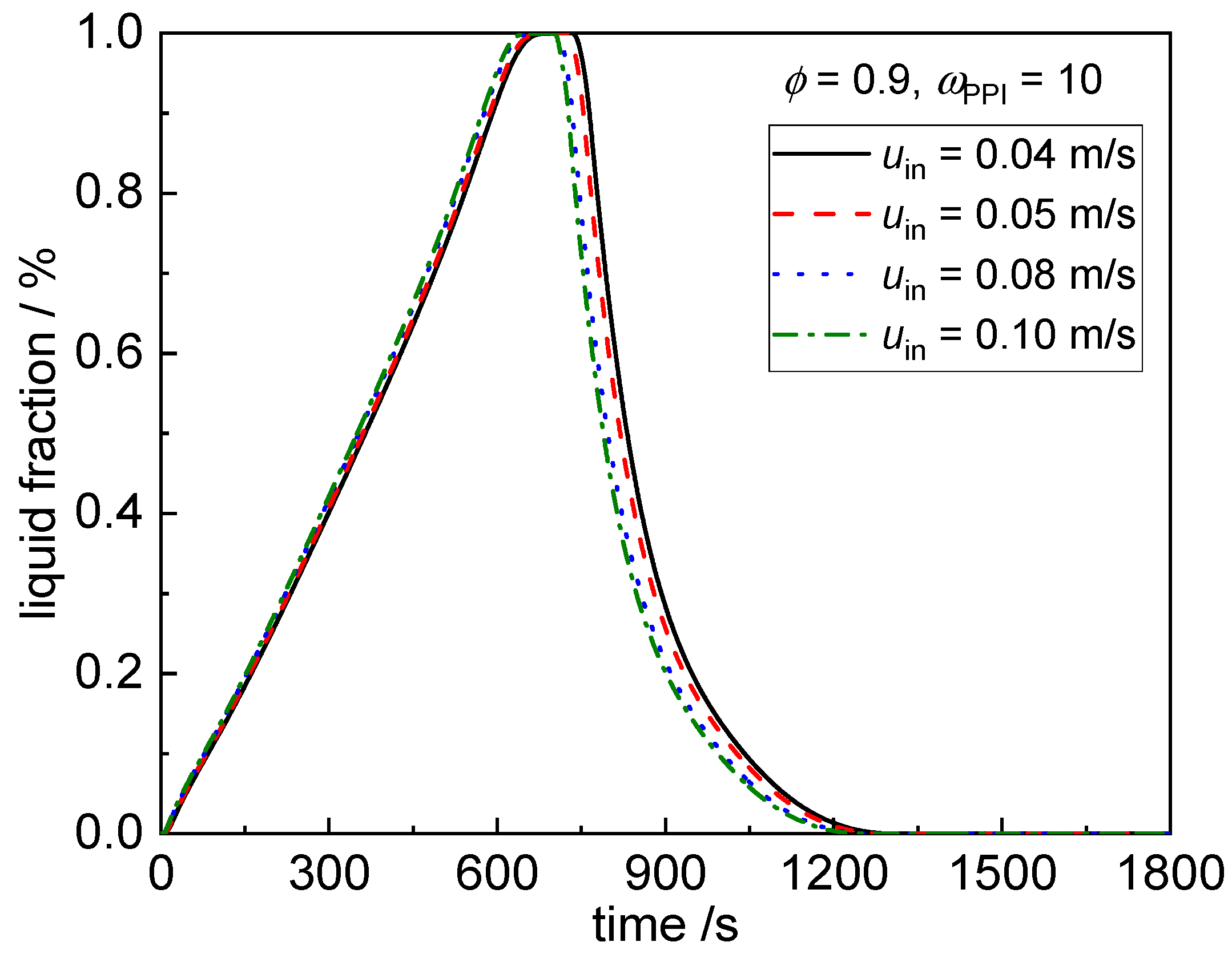
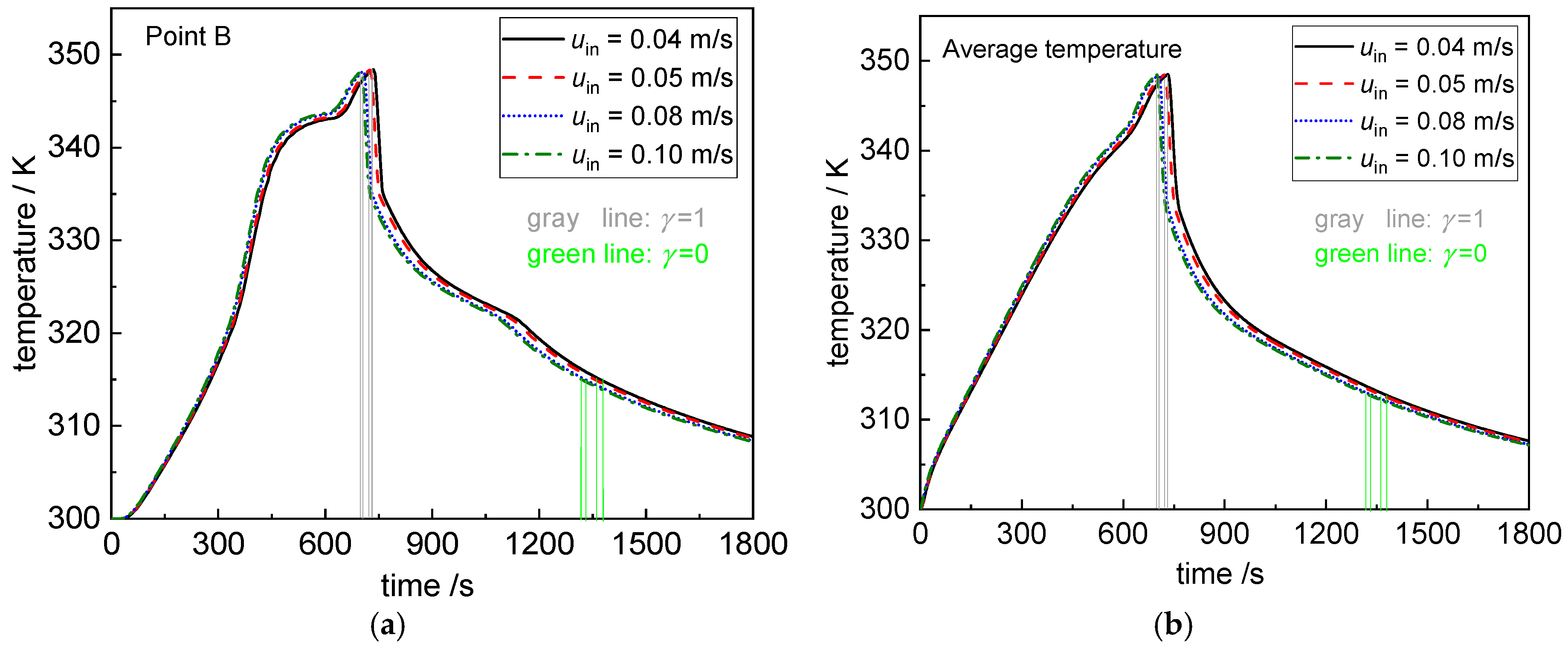
In this section, the effects of HTF inlet conditions and injection side are discussed. Firstly, simulations are performed for four different inlet velocities (0.04 m/s, 0.05 m/s, 0.08 m/s, 0.10 m/s). From Figure 11, it can be concluded that the inlet velocity has a small impact on the whole performance. The rate of charging/discharging has a small increment with the increase of inlet velocity, since the volumetric heat transfer coefficient increases as the velocity increases and more heat can be transferred from HTF to PCM sides through the interface pipe wall. The improvement is not obvious, which is attributed to that the main thermal resistance located in the PCM side. As the velocity increases from 0.04 m/s to 0.1 m/s, the total process time changes from 1379.5 s to 1319.5 s. Additionally, the difference in transient temperature is negligible, as depicted in Figure 12.
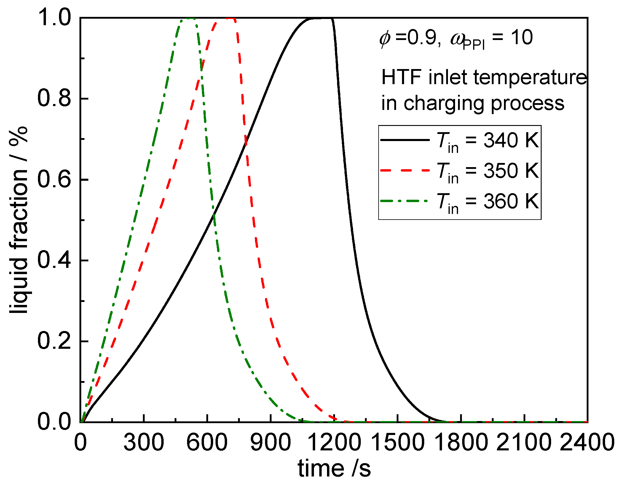
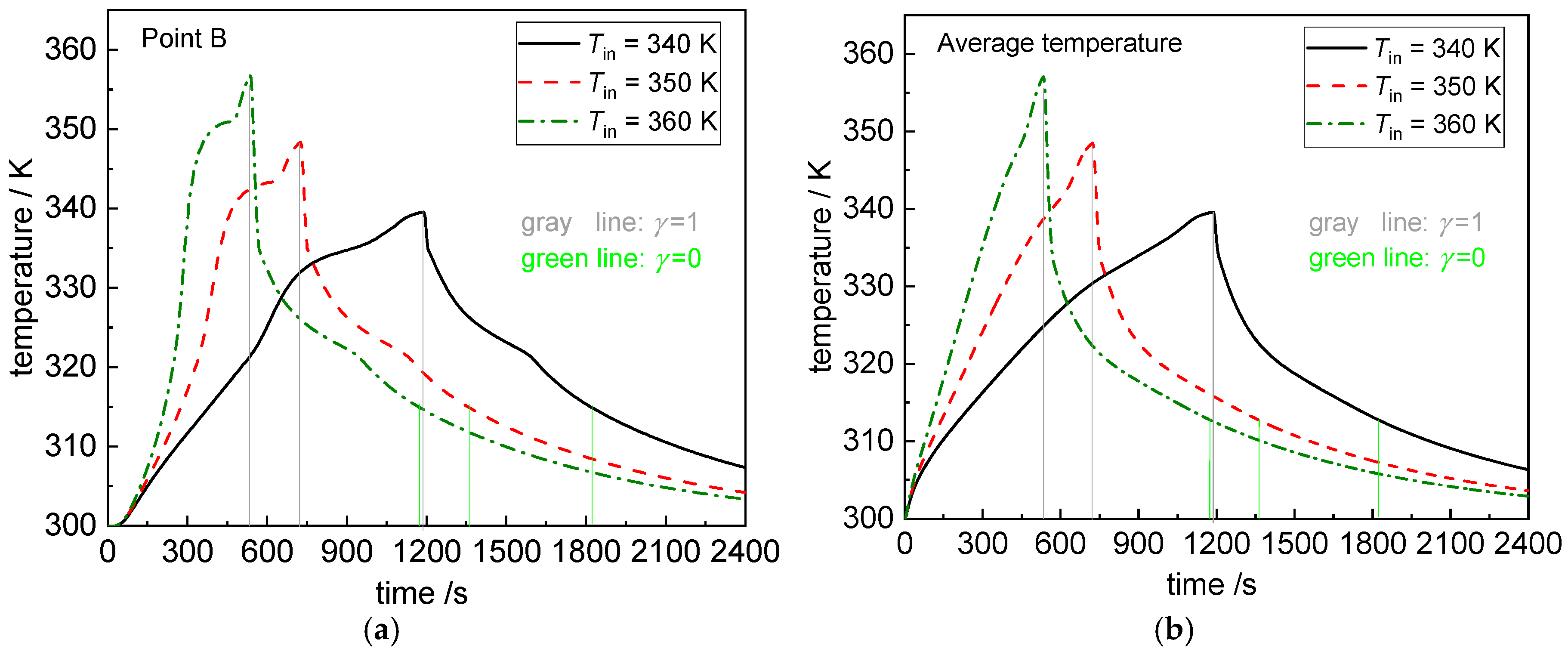
On the other hand, the phase change rate of PCM is greatly increased by increasing the HTF inlet temperature during the charging process, because the temperature difference is the main driven force for the heat exchange. From Figure 13, the total process time is decreased from 1822.5 s to 1176.0 s (nearly a degree of 35.5%), as the inlet temperature increases from 340 K to 360 K. It is observed that increasing the inlet temperature has a greater effectiveness on the melting time reduction, compared to the inlet velocity of HTF. As shown in Figure 14, similar temperature change trends can be noticed, and more dramatic variation is found at a higher inlet temperature due to the higher heat transfer rate.
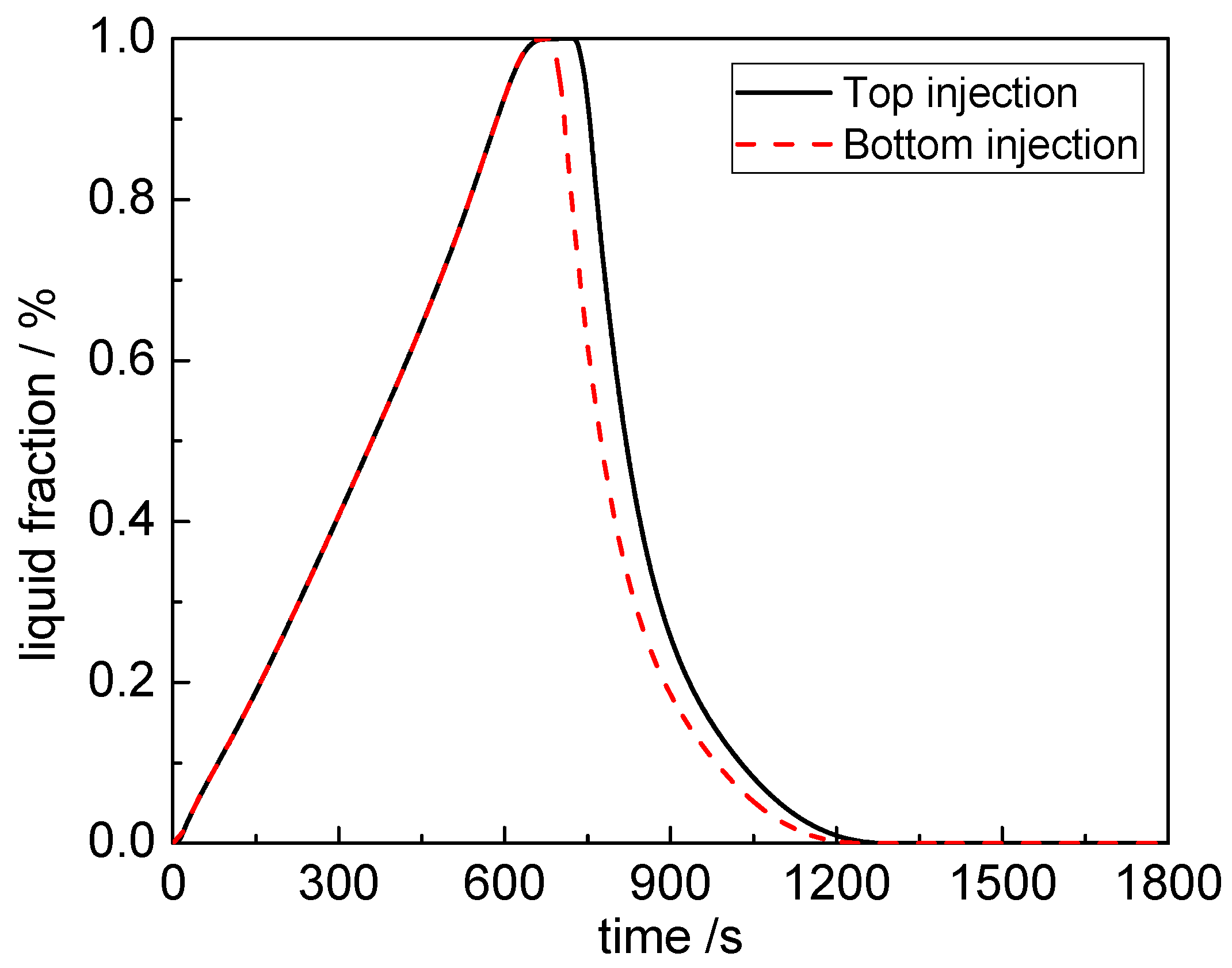
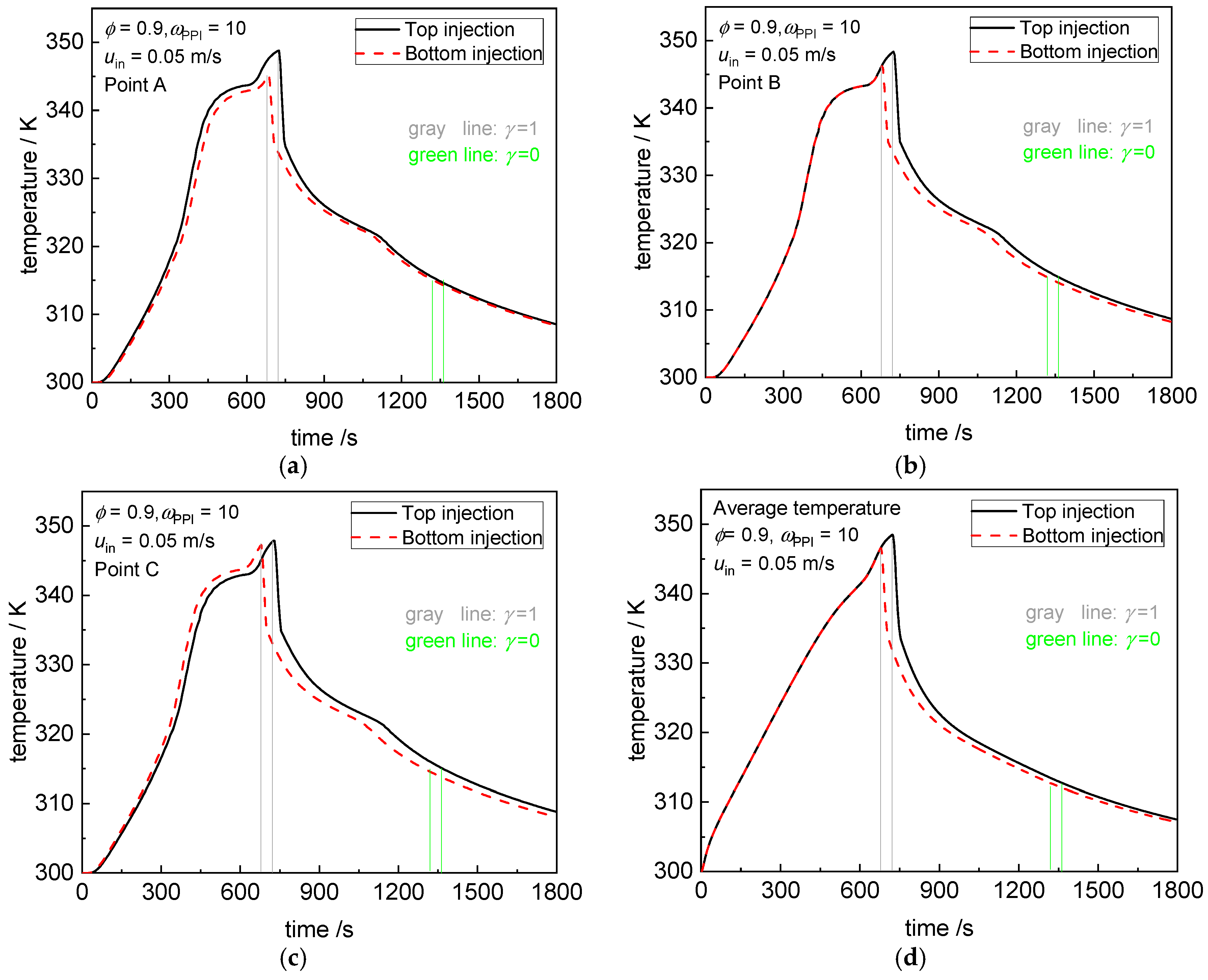
Figure 15 depicts the variation of liquid fraction with time for two injection sides of HTF, one is injection from the top and the other from the bottom. Nearly the same change in the liquid fraction can be found for the two modes during the charging process. The complete melting time is 722.0 s and 677.0 s for the top and bottom injections, respectively. Meanwhile, the discharging time used for the two modes has no great distinction. The total time consumption is 1362.0 s for top injection and 1319.5 s for bottom injection. The results may also indicate that the thermal resistance in PCM side plays a dominant role. From Figure 16, for the bottom injection, the temperature of point C (located below) increases a little more quickly than top injection, and it melts firstly. By progressing time, hot liquid PCM near the interface wall rises to the top due to the natural convection effect, keeping a relatively high temperature difference in the inlet region, which is beneficial to heat exchange. By contrast, for the top injection, the locations above melt firstly (point A firstly reaches the melting temperature as shown in Figure 16), the high temperature HTF is closer to the high temperature PCM, which is not beneficial to heat exchange. Additionally, the point B (located in the middle) has nearly the same temperature during the charging process. Generally, the bottom injection presents a better performance.
5. Conclusions
The whole charging/discharging process for a PCM-based thermal energy storage is numerically investigated. The metal foam is introduced in both the PCM and HTF sides. A comprehensive model is constructed to cope with the physical problem, including the local thermal non-equilibrium effect, coupled heat transfer in the HTF/foam-solid wall-PCM/foam system, and phase change in PCM. Some influential factors are discussed based on the numerical predictions and the following conclusions can be draw.
(1) High energy storage performance is achieved by inserting metal foam in both the HTF and PCM sides. The total charging/discharging time is decreased by 84.9% compared with the case of pure PCM and smooth channel and 40% compared with the case of metal foam only inserted into the PCM side.
(2) Increasing the foam porosity slows down the dynamic variations of liquid fraction and temperature and increases the total time consumption for both cases: fixed PCM mass and fixed TES volume.
(3) As the HTF inlet temperature increases, the total time of the whole charging/discharging process is apparently reduced, and a decrease degree of 35.5% is found in this study. Additionally, the inlet velocity and injection side have no great effect on the TES performance, which means the main thermal resistance still exists in the PCM side when both sides are filled with metal foam.
This study has built a numerical model for the PCM-based thermal energy storage system with a metal foam insert in both the HTF and PCM sides and discussed the effects of some pertinent parameters. Here, the PCM volume expansion during phase change is not considered, which may be another prominent factor affecting the melting/solidification performance. The next work will incorporate the volume expansion effect and perform the experimental test.
Author Contributions
X.X. and R.L. provided the conceptualization. C.S. proposed the methodology and software. X.C. and X.L. performed the validation, simulation, and writing.
Funding
This work is supported by the National Natural Science Foundation of China (no. 51536001, no. 51806046) and the China Postdoctoral Science Foundation (no. 2018M630350).
Conflicts of Interest
The authors declare no conflict of interest.
Nomenclature
| a,b,e | Geometric size of heat exchanger unit, m |
| asf | Specific surface area, m-1 |
| A | Mushy zone constant |
| c | Specific heat, J kg-1 K-1 |
| dp | Pore diameter, m |
| df | Ligament diameter, m |
| hsf | Interfacial heat transfer coefficient, W m-3 K-1 |
| k | Thermal conductivity, W m-1 K-1 |
| K | Permeability, m2 |
| CF | Inertial coefficient, m-1 |
| l | Length of heat exchanger, m |
| p | Pressure, Pa |
| Pr | Prandtl number |
| Red | Reynolds number |
| T | Temperature, K |
| Tliquidus | Liquidus temperature of the PCM, K |
| Tsolidus | Solidus temperature of the PCM, K |
| U | Velocity, m s-1 |
| x, y | Coordinates in computational region, m |
| Greek symbols | |
| β | Thermal expansion coefficient, K−1 |
| μf | Dynamic viscosity, kg m-1 s-1 |
| ρ | Density, kg m-3 |
| ϕ | Porosity |
| ωPPI | Pore in inch |
| δ | Liquid fraction in the porous medium |
| γ | Liquid fraction in the PCM |
| τ | Time, s |
| Subscripts | |
| eff | Effective |
| f | HTF (water) |
| p | PCM |
| in | Inlet |
| s | Solid |
| w | Wall |
References
- Lin, Y.; Jia, Y.; Alva, G.; Fang, G. Review on thermal conductivity enhancement, thermal properties and applications of phase change materials in thermal energy storage. Renew. Sustain. Energy Rev. 2018, 82, 2730–2742. [Google Scholar] [CrossRef]
- Yang, X.; Yu, J.; Guo, Z.; Jin, L.; He, Y.-L. Role of porous metal foam on the heat transfer enhancement for a thermal energy storage tube. Appl. Energy 2019, 239, 142–156. [Google Scholar] [CrossRef]
- Rehman, T.U.; Ali, H.M.; Janjua, M.M.; Sajjad, U.; Yan, W.M. A critical review on heat transfer augmentation of phase change materials embedded with porous materials/foams. Int. J. Heat Mass Transf. 2019, 135, 649–673. [Google Scholar] [CrossRef]
- Giovannelli, A.; Bashir, M.A. Charge and Discharge Analyses of a PCM Storage System Integrated in a High-Temperature Solar Receiver. Energies 2017, 10, 1943. [Google Scholar] [CrossRef]
- Li, D.; Ding, Y.; Wang, P.; Wang, S.; Yao, H.; Wang, J.; Huang, Y. Integrating Two-Stage Phase Change Material Thermal Storage for Cascaded Waste Heat Recovery of Diesel-Engine-Powered Distributed Generation Systems: A Case Study. Energies 2019, 12, 2121. [Google Scholar] [CrossRef]
- Zhao, Y.; You, Y.; Liu, H.; Zhao, C.; Xu, Z. Experimental study on the thermodynamic performance of cascaded latent heat storage in the heat charging process. Energy 2018, 157, 690–706. [Google Scholar] [CrossRef]
- Fleming, E.; Wen, S.; Shi, L.; Da Silva, A.K. Experimental and theoretical analysis of an aluminum foam enhanced phase change thermal storage unit. Int. J. Heat Mass Transf. 2015, 82, 273–281. [Google Scholar] [CrossRef]
- Zhang, P.; Xiao, X.; Ma, Z. A review of the composite phase change materials: Fabrication, characterization, mathematical modeling and application to performance enhancement. Appl. Energy 2016, 165, 472–510. [Google Scholar] [CrossRef]
- Zhao, C.; Lu, W.; Tian, Y. Heat transfer enhancement for thermal energy storage using metal foams embedded within phase change materials (PCMs). Sol. Energy 2010, 84, 1402–1412. [Google Scholar] [CrossRef] [Green Version]
- Cui, H. Experimental investigation on the heat charging process by paraffin filled with high porosity copper foam. Appl. Therm. Eng. 2012, 39, 26–28. [Google Scholar] [CrossRef]
- Lafdi, K.; Mesalhy, O.; Shaikh, S. Experimental study on the influence of foam porosity and pore size on the melting of phase change materials. J. Appl. Phys. 2007, 102, 83549. [Google Scholar] [CrossRef] [Green Version]
- Atal, A.; Wang, Y.; Harsha, M.; Sengupta, S. Effect of porosity of conducting matrix on a phase change energy storage device. Int. J. Heat Mass Transf. 2016, 93, 9–16. [Google Scholar] [CrossRef]
- Martinelli, M.; Bentivoglio, F.; Caron-Soupart, A.; Couturier, R.; Fourmigue, J.-F.; Marty, P. Experimental study of a phase change thermal energy storage with copper foam. Appl. Therm. Eng. 2016, 101, 247–261. [Google Scholar] [CrossRef]
- Yang, J.; Yang, L.; Xu, C.; Du, X. Experimental study on enhancement of thermal energy storage with phase-change material. Appl. Energy 2016, 169, 164–176. [Google Scholar] [CrossRef]
- Mahdi, J.M.; Nsofor, E.C. Melting enhancement in triplex-tube latent heat energy storage system using nanoparticles-metal foam combination. Appl. Energy 2017, 191, 22–34. [Google Scholar] [CrossRef]
- Mahdi, J.M.; Nsofor, E.C. Solidification enhancement in a triplex-tube latent heat energy storage system using nanoparticles-metal foam combination. Energy 2017, 126, 501–512. [Google Scholar] [CrossRef]
- Taghilou, M.; Sefidan, A.M.; Sojoudi, A.; Saha, S.C. Solid-liquid phase change investigation through a double pipe heat exchanger dealing with time-dependent boundary conditions. Appl. Therm. Eng. 2018, 128, 725–736. [Google Scholar] [CrossRef] [Green Version]
- Pourakabar, A.; Darzi, A.R. Enhancement of phase change rate of PCM in cylindrical thermal energy storage. Appl. Therm. Eng. 2019, 150, 132–142. [Google Scholar] [CrossRef]
- Liu, Z.; Yao, Y.; Wu, H. Numerical modeling for solid–liquid phase change phenomena in porous media: Shell-and-tube type latent heat thermal energy storage. Appl. Energy 2013, 112, 1222–1232. [Google Scholar] [CrossRef]
- Esapour, M.; Hamzehnezhad, A.; Darzi, A.A.R.; Jourabian, M. Melting and solidification of PCM embedded in porous metal foam in horizontal multi-tube heat storage system. Energy Convers. Manag. 2018, 171, 398–410. [Google Scholar] [CrossRef]
- Shahsavar, A.; Al-Rashed, A.A.; Entezari, S.; Sardari, P.T. Melting and solidification characteristics of a double-pipe latent heat storage system with sinusoidal wavy channels embedded in a porous medium. Energy 2019, 171, 751–769. [Google Scholar] [CrossRef]
- Kumar, A.; Saha, S.K. Latent heat thermal storage with variable porosity metal matrix: A numerical study. Renew. Energy 2018, 125, 962–973. [Google Scholar] [CrossRef]
- Lopez, J.P.A.; Kuznik, F.; Baillis, D.; Virgone, J. Numerical modeling and experimental validation of a PCM to air heat exchanger. Energy Build. 2013, 64, 415–422. [Google Scholar] [CrossRef]
- Chen, X.; Wang, F.; Han, Y.; Yu, R.; Cheng, Z. Thermochemical storage analysis of the dry reforming of methane in foam solar reactor. Energy Convers. Manag. 2018, 158, 489–498. [Google Scholar] [CrossRef]
- Li, W.; Qu, Z.; He, Y.; Tao, W. Experimental and numerical studies on melting phase change heat transfer in open-cell metallic foams filled with paraffin. Appl. Therm. Eng. 2012, 37, 1–9. [Google Scholar] [CrossRef]
- Zhang, H.J.; Zou, Z.P.; Li, Y.; Ye, J. Preconditioned Density-Based Algorithm for Conjugate Porous/Fluid/Solid Domains. Numer. Heat Transf. Part A Appl. 2011, 60, 129–153. [Google Scholar] [CrossRef]
- Chen, X.; Sun, C.; Xia, X.; Liu, R.; Wang, F. Conjugated heat transfer analysis of a foam filled double-pipe heat exchanger for high-temperature application. Int. J. Heat Mass Transf. 2019, 134, 1003–1013. [Google Scholar] [CrossRef]
- Calmidi, V.V.; Mahajan, R.L. Forced Convection in High Porosity Metal Foams. J. Heat Transf. 2000, 122, 557–565. [Google Scholar] [CrossRef]
- Boomsma, K.; Poulikakos, D. On the effective thermal conductivity of a three-dimensionally structured fluid-saturated metal foam. Int. J. Heat Mass Transf. 2001, 44, 827–836. [Google Scholar] [CrossRef]
- Krishnan, S.; Murthy, J.Y.; Garimella, S.V. A Two-Temperature Model for Solid-Liquid Phase Change in Metal Foams. J. Heat Transf. 2005, 127, 995–1004. [Google Scholar] [CrossRef]
- Fang, Y.; Niu, J.; Deng, S. Numerical analysis for maximizing effective energy storage capacity of thermal energy storage systems by enhancing heat transfer in PCM. Energy Build. 2018, 160, 10–18. [Google Scholar] [CrossRef]
Figure 1.
Schematic of the phase change material PCM slab and water flow within the thermal energy storage TES system.
Figure 1.
Schematic of the phase change material PCM slab and water flow within the thermal energy storage TES system.

Figure 2.
Temperature comparison of numerical results by present work with literature for melting process in a PCM/foam composite.
Figure 2.
Temperature comparison of numerical results by present work with literature for melting process in a PCM/foam composite.

Figure 3.
Temperature comparison in the PCM/foam composite with literatures.

Figure 4.
Variation of outlet temperature over time during the charging process.

Figure 5.
Comparison of the PCM liquid fraction for the four cases.

Figure 6.
PCM temperature versus time in the charging and discharging processes: (a) Point A; (b) Point B; (c) Point C; (d) average temperature.
Figure 6.
PCM temperature versus time in the charging and discharging processes: (a) Point A; (b) Point B; (c) Point C; (d) average temperature.

Figure 7.
Effect of the foam porosity on the liquid fraction at the fixed PCM mass.

Figure 8.
Effect of the foam porosity on the PCM temperature change at fixed PCM mass: (a) Point B; (b) average temperature.
Figure 8.
Effect of the foam porosity on the PCM temperature change at fixed PCM mass: (a) Point B; (b) average temperature.

Figure 9.
Effect of the foam porosity on the liquid fraction at the fixed TES volume.

Figure 10.
Effect of the foam porosity on the PCM temperature change at fixed TES volume: (a) Point B; (b) average temperature.
Figure 10.
Effect of the foam porosity on the PCM temperature change at fixed TES volume: (a) Point B; (b) average temperature.

Figure 11.
Effect of the heat transfer fluid HTF velocity on the liquid fraction during the whole process.
Figure 11.
Effect of the heat transfer fluid HTF velocity on the liquid fraction during the whole process.

Figure 12.
Effect of the HTF velocity on the PCM temperature change: (a) Point B; (b) average temperature.
Figure 12.
Effect of the HTF velocity on the PCM temperature change: (a) Point B; (b) average temperature.

Figure 13.
Effect of the HTF temperature on the liquid fraction during the whole process.

Figure 14.
Effect of the HTF temperature on the PCM temperature change: (a) Point B; (b) average temperature.
Figure 14.
Effect of the HTF temperature on the PCM temperature change: (a) Point B; (b) average temperature.

Figure 15.
Effect of the HTF injection side on the liquid fraction during whole process.

Figure 16.
Effect of the HTF injection side on temperature change: (a) Point A; (b) Point B; (c) Point C; (d) average temperature.
Figure 16.
Effect of the HTF injection side on temperature change: (a) Point A; (b) Point B; (c) Point C; (d) average temperature.


Table 1.
Thermo-physical properties of the materials used in this study.
| Property | Paraffin RT 58 | Water | Cu | Stainless Steel |
|---|---|---|---|---|
| Density (kg m−3) | 840 | 998.2 | 8978 | 8030 |
| Specific heat (J kg−1 K−1) | 2100 | 4182 | 381 | 502.48 |
| Thermal conductivity (W m−1 K−1) | 0.2 | 0.6 | 387.6 | 16 |
| Dynamic viscosity (kg m−1 s−1) | 0.0269 | 0.001003 | − | − |
| Latent heat (kJ kg−1) | 181 | − | − | − |
| Thermal expansion coefficient (K−1) | 1.1 × 10⁻⁴ | − | − | − |
| Melting temperature range (K) (solidus and liquidus temperatures) | 321–335 | − | − | − |
Table 2.
Time consumption of the thermal energy storage TES working for the four cases.
| Case | Charging Time (s) | Discharging Time (s) | Total Time (s) |
|---|---|---|---|
| case (1) | 5174.5 | 3837.5 | 9012.0 |
| case (2) | 4704.0 | 3708.5 | 8412.5 |
| case (3) | 1200.5 | 1065.5 | 2266.0 |
| case (4) | 722.0 | 640.0 | 1362.0 |
Table 3.
Time consumption for different operating conditions investigated in the next sections.
| Foam porosity (fixed PCM mass) | charging time (s) | discharging time (s) | total time (s) |
| 0.85 | 711.5 | 620.0 | 1331.5 |
| 0.9 | 722.0 | 640.0 | 1362.0 |
| 0.95 | 799.5 | 689.0 | 1488.5 |
| Foam porosity (fixed TES volume) | charging time (s) | discharging time (s) | total time (s) |
| 0.85 | 670.0 | 594.0 | 1264.0 |
| 0.9 | 722.0 | 640.0 | 1362.0 |
| 0.95 | 852.5 | 724.5 | 1577.0 |
| Inlet velocity (m/s) | charging time (s) | discharging time (s) | total time (s) |
| 0.04 | 731.0 | 648.5 | 1379.5 |
| 0.05 | 722.0 | 640.0 | 1362.0 |
| 0.08 | 705.5 | 625.5 | 1331.0 |
| 0.1 | 699.5 | 620.0 | 1319.5 |
| Inlet temperature (K) | charging time (s) | discharging time (s) | total time (s) |
| 340 | 1186.0 | 636.5 | 1822.5 |
| 350 | 722.0 | 640.0 | 1362.0 |
| 360 | 532.5 | 643.5 | 1176.0 |
| Injection side | charging time (s) | discharging time (s) | total time (s) |
| Top injection | 722.0 | 640.0 | 1362.0 |
| Bottom injection | 677.0 | 642.5 | 1319.5 |
© 2019 by the authors. Licensee MDPI, Basel, Switzerland. This article is an open access article distributed under the terms and conditions of the Creative Commons Attribution (CC BY) license (http://creativecommons.org/licenses/by/4.0/).
Share and Cite
MDPI and ACS Style
Chen, X.; Li, X.; Xia, X.; Sun, C.; Liu, R. Thermal Performance of a PCM-Based Thermal Energy Storage with Metal Foam Enhancement. Energies 2019, 12, 3275. https://0-doi-org.brum.beds.ac.uk/10.3390/en12173275
AMA Style
Chen X, Li X, Xia X, Sun C, Liu R. Thermal Performance of a PCM-Based Thermal Energy Storage with Metal Foam Enhancement. Energies. 2019; 12(17):3275. https://0-doi-org.brum.beds.ac.uk/10.3390/en12173275
Chicago/Turabian StyleChen, Xue, Xiaolei Li, Xinlin Xia, Chuang Sun, and Rongqiang Liu. 2019. "Thermal Performance of a PCM-Based Thermal Energy Storage with Metal Foam Enhancement" Energies 12, no. 17: 3275. https://0-doi-org.brum.beds.ac.uk/10.3390/en12173275
Note that from the first issue of 2016, this journal uses article numbers instead of page numbers. See further details here.