Experiments on Air Compression with an Isothermal Piston for Energy Storage


1
School of Automation Science and Electrical Engineering, Beihang University, Beijing 100191, China
2
Pneumatic and Thermodynamic energy storage and supply Beijing Key Laboratory, Beijing 100191, China
*
Author to whom correspondence should be addressed.
Energies 2019, 12(19), 3730; https://0-doi-org.brum.beds.ac.uk/10.3390/en12193730
Submission received: 24 August 2019
/
Revised: 20 September 2019
/
Accepted: 25 September 2019
/
Published: 29 September 2019
Abstract
:Air is usually compressed adiabatically in the compressor. As the operating speed of compressors can be several thousand rpm, heat generated during compression cannot be sufficiently transmitted to the environment in such a short time. It is for this reason that compressor efficiency is limited. Isothermal compression could be an alternative choice applied on industrial compressor and compressed air energy storage (CAES). This paper proposed a new kind of piston to perform isothermal compression. Surface area of such isothermal piston structure is larger. A certain amount of fluid at the chamber bottom absorbs the heat from the isothermal piston. Heat transfer between piston and fluid during compression is investigated. Air pressure is measured to validate the effectiveness of this proposed piston structure in heat transfer. Compression work of the proposed isothermal piston and conventional one is compared. One issue of this comparison is that air-liquid dissolution can affect the pressure and compression work. The influence of dissolution is quantified with Henry’s Law. Quantitative analysis is performed to determine that heat transfer is the dominant factor affecting the pressure and compression work. Some simple experiments are described in this paper, which shed light on that heat transfer could be significantly improved adopting this proposed isothermal piston.
1. Introduction
Pneumatic system is one of the three major power transmission systems in modern manufacturing, with the other two being electrical and hydraulic systems. Air compressors consume 5%–50% of the total energy of the whole manufacturing industry. They are driven by electrical motors and electricity consumption of industrial compressors accounts for about [1] 9% of China’s total electricity consumption (~6844 TWh in 2018).
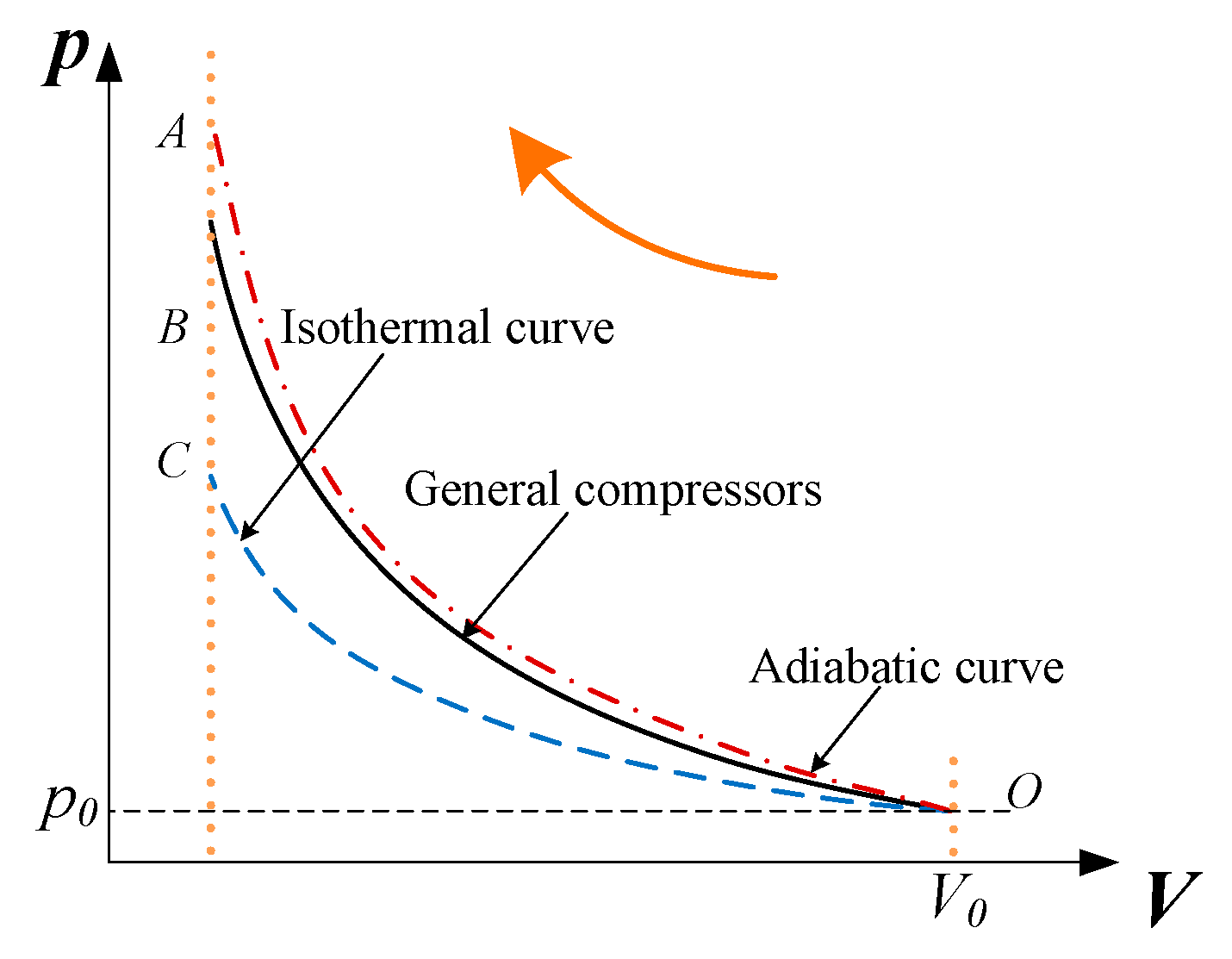
The way air is compressed can be classified as adiabatic, isothermal [2], and non-adiabatic, according to the degree of heat transfer between air and environment. The changing process of compressed air is presented by the p-V diagram (Figure 1). The O-A curve represents the adiabatic compression, while the O-C curve represents the isothermal compression. The difference lies in the compressed air temperature. For adiabatic compression, air is totally insulated and temperature rises greatly with compression proceeding. While for isothermal compression, heat transfer between air and environment is sufficient and air temperature remains constant.
Most compressors work under near adiabatic conditions. Considerable compression work is stored as the form of heat and reused during the discharging process. However, the cycle efficiency of compressors is greatly limited by the poor heat transfer. Energy consumption is minimum when compression is under isothermal condition. In order to improve compressor efficiency, study on enhancement of heat transfer is essential to achieve isothermal compression.
Isothermal compression could potentially be applied to compressed air energy storage systems [3]. The concept of compressed air energy storage (CAES) was first proposed in the 1940s. The first CAES power station was put into operation in Germany in 1978, with a power capacity of 290 MW [4]. The reported efficiency is 54%. Compared with other energy storage systems, such as flywheels (85%–95%) and batteries (over 90%), the turnaround efficiency of CAES systems is relatively low [5].
There are two main approaches to improve the turnaround efficiency of CAES system: (1) compression in adiabatic condition and recycling the compression heat; (2) compression in isothermal condition to reduce the compression heat.
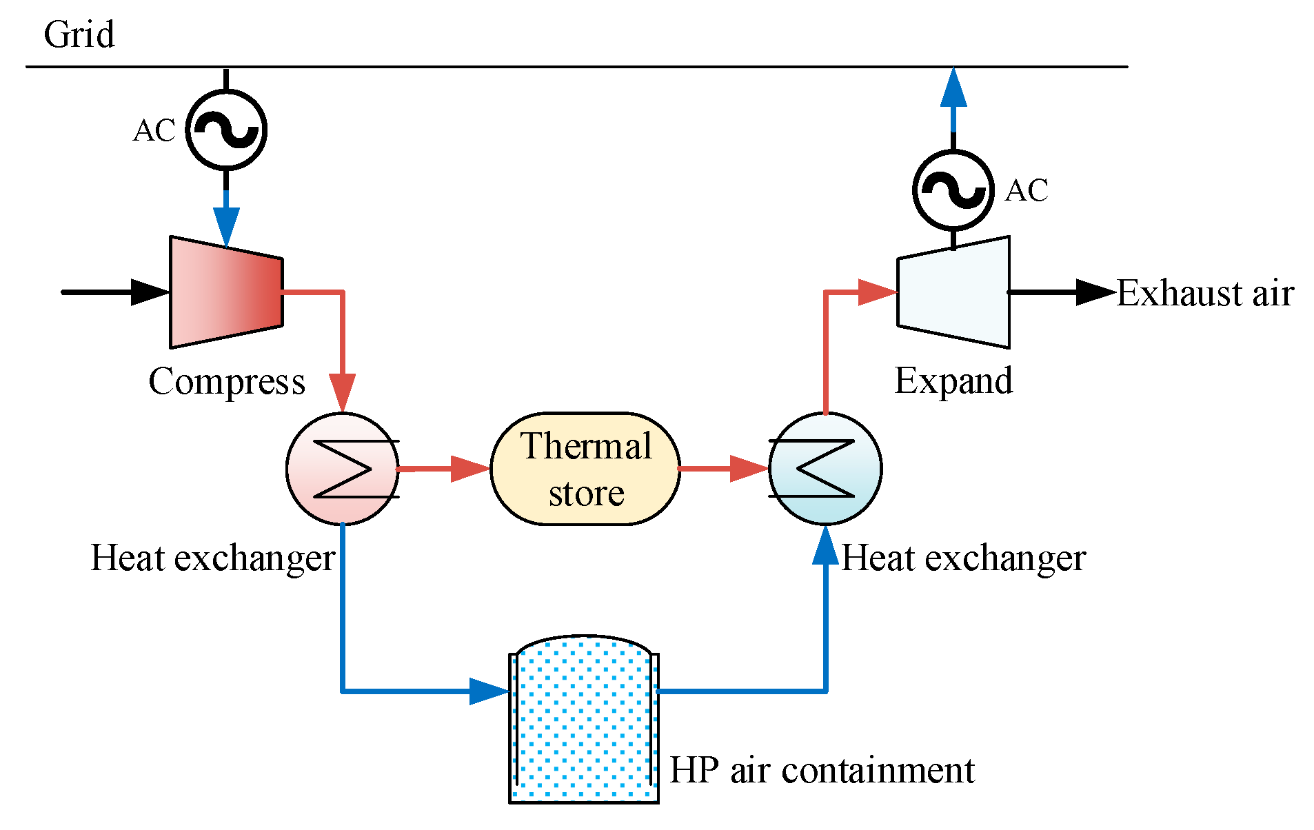
Figure 2 shows the CAES system with adiabatic compression [6]. Electricity from the grid is used to compress air, and the energy is converted to pressured air and thermal energy. Thermal energy accounts for approximately 20%–40% of the total energy, stored in the thermal store. The rest of the energy is stored in the High Pressure (HP) air containment as pressured air.
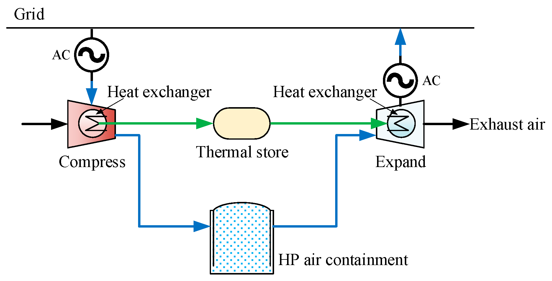
Figure 3 shows the isothermal CAES system. The main difference is that compression is accompanied with heat exchange, which means heat exchange happens inside the compressor. Air temperature is much lower than the adiabatic CAES system. Due to enhanced heat transfer, much less thermal energy is generated and heat loss that results from heat exchange will become less. Most energy will be stored in the HP air containment. The total cost of energy storage would be increased if steel vessels are used as the HP air containment [7].
Isothermal CAES systems are suitable for region with caverns as cost of HP air storage can be greatly reduced. The caverns could be underground rock formation [8]. Natural environmental characteristics as the static pressure in the rock should be utilized. Reported results showed that the cost of compressed air in salt cavern does not exceed $1/m3 [9]. The same may be true for storing HP air in deep underwater containments. A cable-reinforced fabric vessel [10] is designed to store HP air for energy storage. The reported results show that the energy bag can provide cost-effective high-pressure air storage and be used for compressed air storage plants at sea and onshore.
At present, two methods are mainly used to achieve isothermal compression: (1) adopting a liquid piston structure to increase heat exchange area [11]; (2) injecting liquid spray or foam into the compression chamber to enhance heat transfer.
For the basic concept of liquid piston, a column of liquid is utilized to directly compress gas in a chamber of fixed volume. James D. and Perry Li [12,13,14] experimentally investigated the heat transfer and the friction loss of a liquid piston. Compared with the conventional reciprocating piston, heat transfer is improved using this proposed liquid piston. The reported compression efficiency (83%) of the liquid piston is higher than that of the reciprocating piston (70%).
Liquid piston has the advantage that the liquid column can conform to an irregularly shaped gas chamber, thus heat transfer area can be improved. Other advantages lie in reducing air leakage and friction resistance [15]. However, the liquid piston is driven by a hydraulic system. Air will be mixed with the liquid. Consequently, elastic modulus of the liquid will decrease, and other problems such as noise, vibration, intensively wear, and cavitation in low pressure regions arise.
The other method is to mix the injected water spray or foam [16] with air in the compression chamber in order to absorb generated compression heat. Coney [17] first proposed and verified that injecting water spray directly into the compression chamber can significantly reduce compression work of a reciprocating compressor. The volume of the compression chamber in the study is 46 L with the maximum pressure ratio of 25. The results manifested that the air temperature can be below 100 °C compared with 500 °C in adiabatic condition. The compression work is reduced by 28%. SustainX [16] proposed a compressor that allows foam to come into the compression chamber. This foam is created with a mixture of air and water before it enters the compression chamber. Advantages of foam are less energy required for generation and longer time it stays in the compression chamber.
The liquid injection offers additional heat transfer area to the compression chamber. The heat transfer area depends on the droplet size of the liquid. This provides a different route to improve the heat transfer area by reducing the droplet size of the liquid. However, a higher pressure is required (3–5 MPa) to generate a smaller size (micron size) of droplets. Besides, higher pressure increased water spray mass, and this leads to a greater energy consumption for the generation. Work generated for water spray equals to the saved compression work when the water spray mass reaches to 1.5 g/cycle (nozzle in diameter of 0.3 mm) [18]. New methods are required to both reduce the droplet size and the energy consumption.
2. Isothermal System
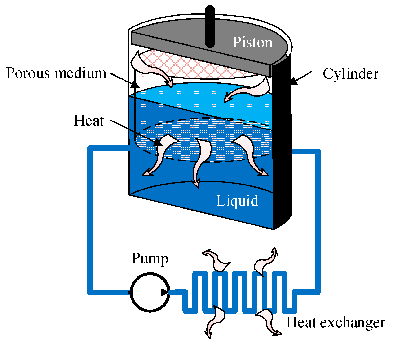
This study proposes a new compression system which can realize isothermal compression. Such system principle diagram is shown in Figure 4. Porous medium [19] and liquid are contained in the compression chamber, and the other part is filled with air, forming a gas-solid-liquid coupled structure. Larger surface area between air and liquid is created with the porous medium, which tremendously enhances heat transfer. Part of the porous contacts with the air and the other part is submerged into the liquid.
When compressed, heat of compression is transferred to the porous medium and then to the liquid. In consequence, air temperature is close to that of the liquid due to the great heat transfer area. As heat capacity of the liquid is large enough, liquid temperature remains almost unchanged. In practical application, the liquid will circulate to dissipate heat to the environment by an external heat exchanger in order to keep temperature constant.
3. Experiment Setup
An experiment platform was set up to verify the effectiveness of the proposed isothermal piston. Thermodynamic characteristics of the isothermal piston were compared with conventional condition.
3.1. Measurement Methods
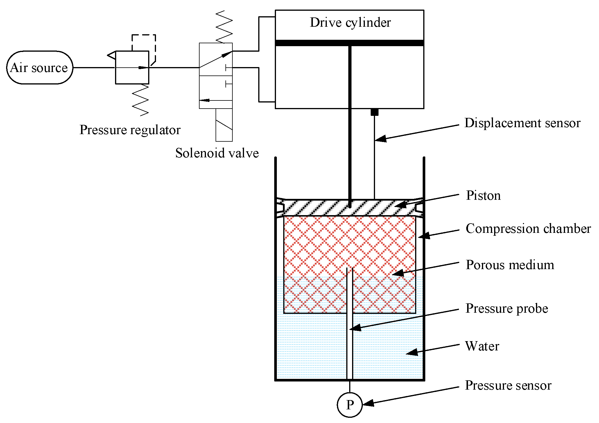
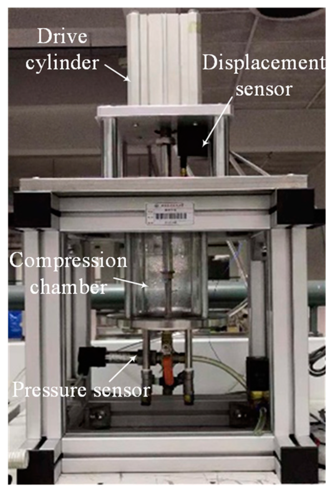
The schematic and the experimental platform are shown in Figure 5 and Figure 6 respectively. The experimental platform consists of a driving cylinder, a compression chamber, a pressure regulating valve, a solenoid valve, a pressure sensor, and a displacement sensor. The parameters of the experimental equipment is shown in Table 1.
The isothermal piston is driven by an air cylinder. Supply pressure of air source is 0.8 MPa, and a pressure regulator is connected behind to regulate actuating pressure of the drive cylinder, which is to alter the force applied to the isothermal piston. The solenoid valve is to control the direction of piston motion. In this study, the system operated one cycle, and we only focused on the compression process.
The compression chamber is made of a tempered glass cylinder with wall thickness of 15 mm (volume = 1.35 L, inner diameter = 100 mm, height = 120 mm). The piston is made of a rubber material with V-shaped structure for sealing air leaks. To measure the air pressure in the chamber, a tube that is out of the water is mounted at the bottom. A pressure sensor is connected with the tube to measure the pressure of compressed air in real time. A displacement sensor is installed on the piston to monitor the position.
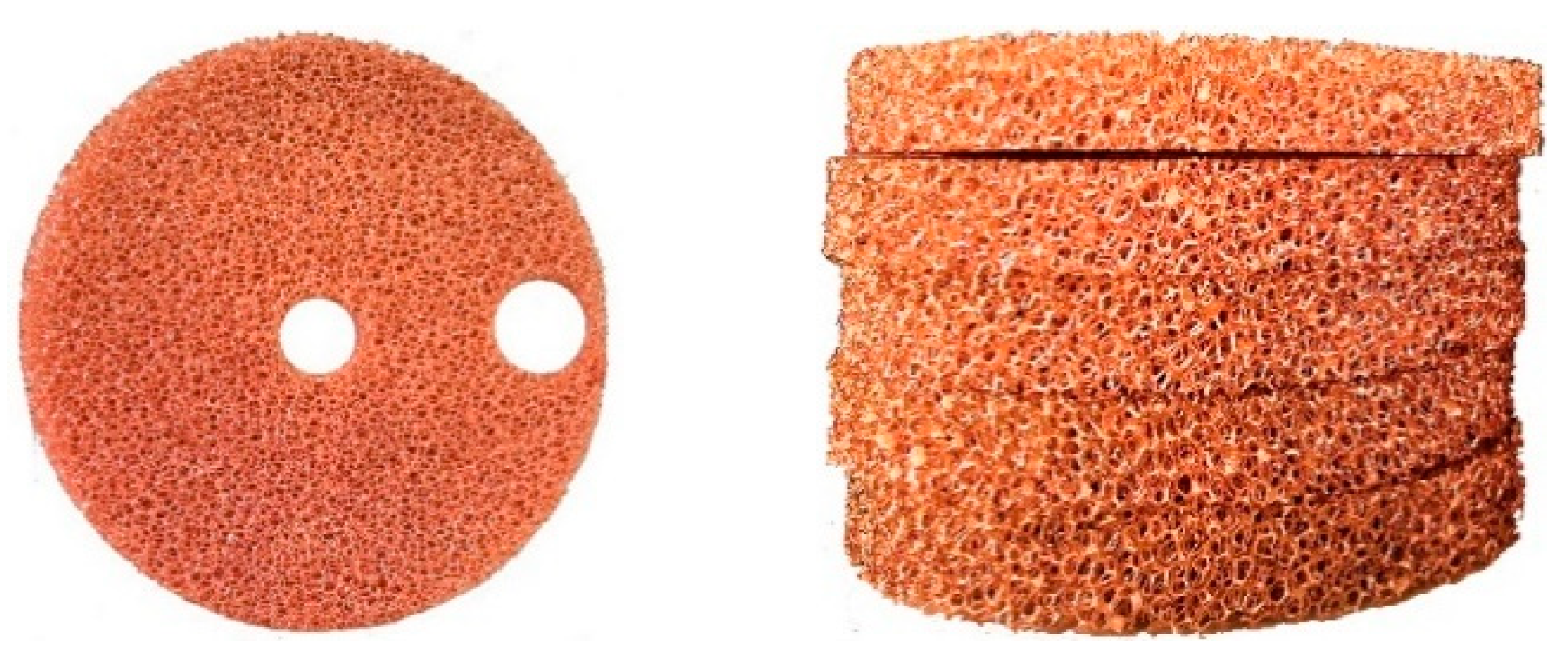
The porous medium used in the experiments was a foamed metal copper. Foam metals are commonly used engineering material. These materials both have nice conduction of metals and great surface area of porous mediums. Figure 7 shows the foam copper that was used in this study. Thickness of each piece was 10 mm. Eight pieces were stacked and are mounted under the piston. Property of the foam metal is list in Table 2. Two holes were made on each piece, one in the middle for the piston rod and the other on the side for the tube of pressure sensor.
Water was used as the liquid in this study. A certain amount of water was in the chamber. First, the piston goes downward, and air is compressed. When it reaches the extreme position, the piston goes upward to the original position. In such one cycle, data of all sensors were acquired and analyzed in the compression process. Each experiment was repeated three times and data of each set was consistent.
Two control experiments were also performed. One is that there was water but no porous media, and the other is that there was no water and porous media.
3.2. Measurement of Volume
Since the geometry of the compression chamber is a standard cylinder, the air volume in the compression chamber can be measured based on the displacement of the piston:
where, V0 denotes the initial volume of the compression chamber. Sp denotes cross-sectional area of the piston. x denotes the displacement of the piston. The resolution accuracy of the displacement sensor is 0.04 mm. This equals 0.03% of the total length of the compression chamber.
3.3. Formatting of Mathematical Components
During the compression process, compression work performed by the piston can be expressed as:
Air volume in the compression chamber was measured according to Section 3.2. The pressure was measured according to Section 3.1. As the pressure wave propagates at a high speed, it can be considered that pressure is evenly distributed in the compression chamber.
4. Results and Discussion
4.1. Air Dissolution
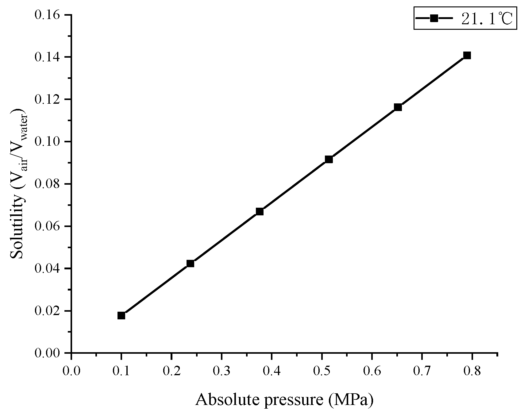
Air pressure increases as compression proceeds, causing air to dissolve into water constantly as a consequence [20]. According to Henry’s law [20], the amount of dissolved gas in a liquid is proportional to its partial pressure above the liquid:
where c (mol/L) is the molarity of gas dissolved in the liquid; p is the gas pressure above the liquid at equilibrium conditions; Hcp (mol/L∙atm) is Henry’s Law constant, and it is independent of temperature. Reference [21] presents Henry’s law constants of O2 and N2 in water at 298.15 K, which are 1.3 × 10⁻³ and 6.1 × 10⁻⁴. Since air consists mainly of O2 (22%) and N2 (78%), the Henry’s law constants of air can be obtained by the proportion of these two gases.
Figure 8 shows the air solubility at different pressures, which are in proportional relation [22]. At the max pressure of air (around 0.6 MPa) in this study, more than 10% of the air is dissolved. Therefore, air dissolution in this experiment is nonnegligible in this study.
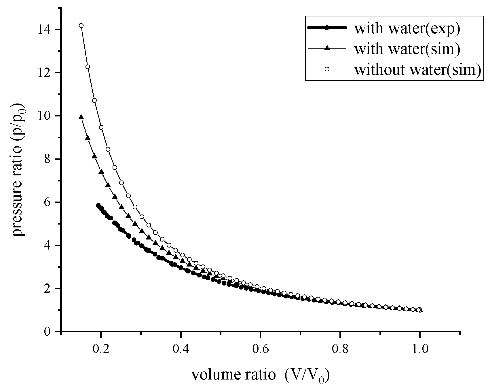
Porous media is excluded in the dissolution experiment. The amount of dissolution is explored through contrast experiments. It is equivalent of adiabatic compression under two conditions: with water and without water. Based on ideal gas state Equation (4), air pressure with water condition is lower at the same compression state due to air loss by dissolution.
For the former, water was added to keep the piston just above the water surface at downward utmost position in the first experiment, which had a volume of 0.775 L. A case-control experiment is compression without water in the chamber. The air mass in the chamber should be the same as the former experiment. Therefore, a filler that occupies the same amount of volume of water in the former experiment should be added in the chamber. However, heat transfer occurs from the compressed air to the filler, which leads to pressure drop as well. Therefore, the case-control experiment is instead by simulation of ideal adiabatic compression according to Equations (3) and (4). Molarity is converted to mass expression in the calculation.
Results are shown in Figure 9. For compression with water, the experimental pressure is a little bit lower than simulation at the same volume ratio. It reveals that the experiment is not an ideal adiabatic condition, and a certain amount of heat is transferred from compressed air to the wall. Therefore, the pressure will be a little lower. When comparing compression with and without water, the pressure with water is lower than that without water. It indicates that the mass of air above water is reduced.
4.2. Effect of Air Dissolution and Heat Transfer
In this section, the effect of heat transfer of compression is explored through contrast experiments by conventional (with porous media) and isothermal (without porous media) pistons. The diameter and stroke of the piston were 100 mm and 65.5 mm respectively. As the cylinder was the same in these two experiments, heat loss to the surroundings was kept at roughly equal levels. The inlet pressure of driving cylinder was set to 0.7 MPa, hence the same force was applied to the piston for the contrast experiments. Other detailed parameters related to the experiments are shown in Table 2. For porosity of the foam copper, it is given as:
where Va is apparent volume, and Vs is absolute compact volume of foam copper.
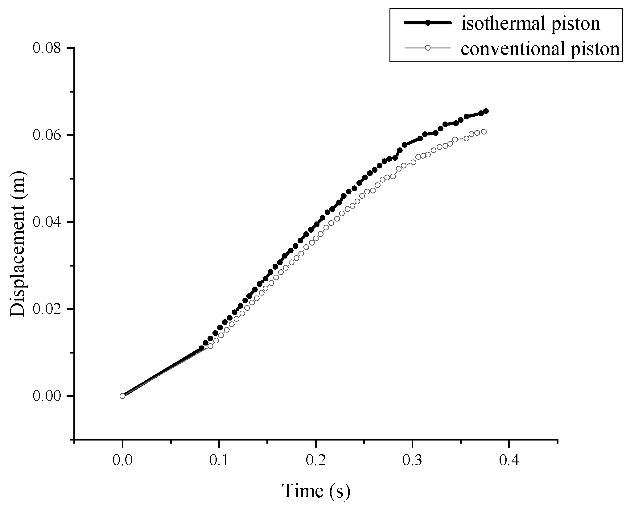
The displacement of the piston in such two occasions is depicted in Figure 10. The speed of isothermal piston is slightly faster than conventional piston (average 7.25%). This reflects that the air pressure with the isothermal piston is lower than that with the conventional piston since driving force applied on these two occasions is the same.
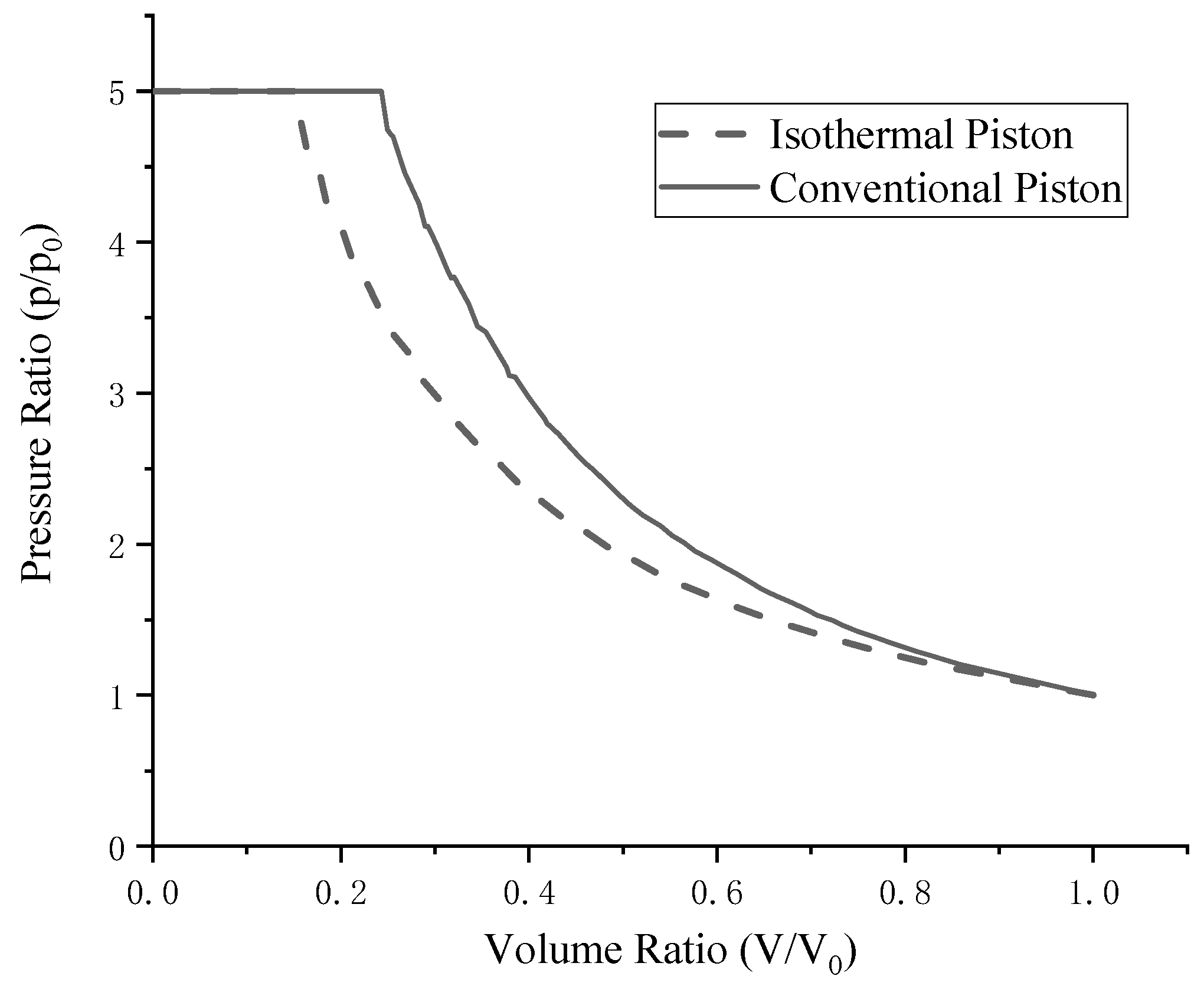
The p-V curves are shown in Figure 11 (normalized by the initial volume). The pressure with the isothermal piston is lower than with the conventional piston. It can be seen that the pressure difference enlarges as compression proceeds.
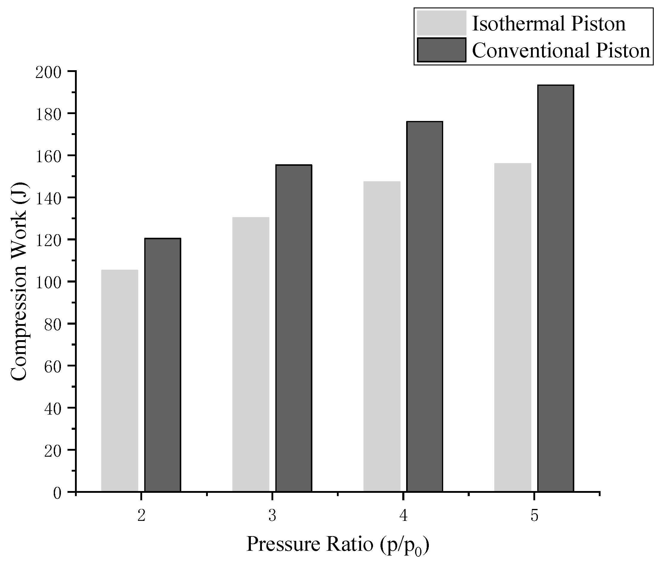
Based on p-V curves, compression work can be obtained by integrals. Compression work at four pressure ratios are shown in Figure 12. This does not include work to overcome frictional forces. For ease of expression, the footnote 1 is for the isothermal piston, and footnote 2 is for the conventional piston. Work reduction by isothermal piston as shown in Figure 12 can be expressed as:
Apparently, compression work is lowered with isothermal piston, from 193.4 to 156.0 J (by 19.3%). The higher the compression ratio, the greater work saved. Here it cannot be concluded that the saved work is all by the increased heat transfer. Air dissolved is also varied with pressure, and that will affect compression work in turn. Therefore, the part of saved work that is caused by difference of mass loss should be eliminated.
Work influenced by dissolution can be expressed as:
where T is air pressure, and dmdis is mass loss. Work difference of such two experiments related to dissolution can be acquired:
Then, work saved by increased heat transfer is as Equation (11), it is the result of removing more heat during the compression process, thus lowering the work required to compress the gas.
Substituting Equations (7) and (8) into Equation (9), we obtain Equation (10) as follows.
From Equation (10), △WQ relates to the mass of dissolved air and air temperature. The mass of dissolved air can be determined by the air pressure drop according to Henry’s law as Equation (3), where the molar mass of air is 29 g/mol. The response time of pressure sensor is 0.2 ms, which is far less than the time for compression (0.2 s) and it meets the measurement requirements. However, the measurement of temperature is challenging as the response time of a typical temperature is in the order of seconds.
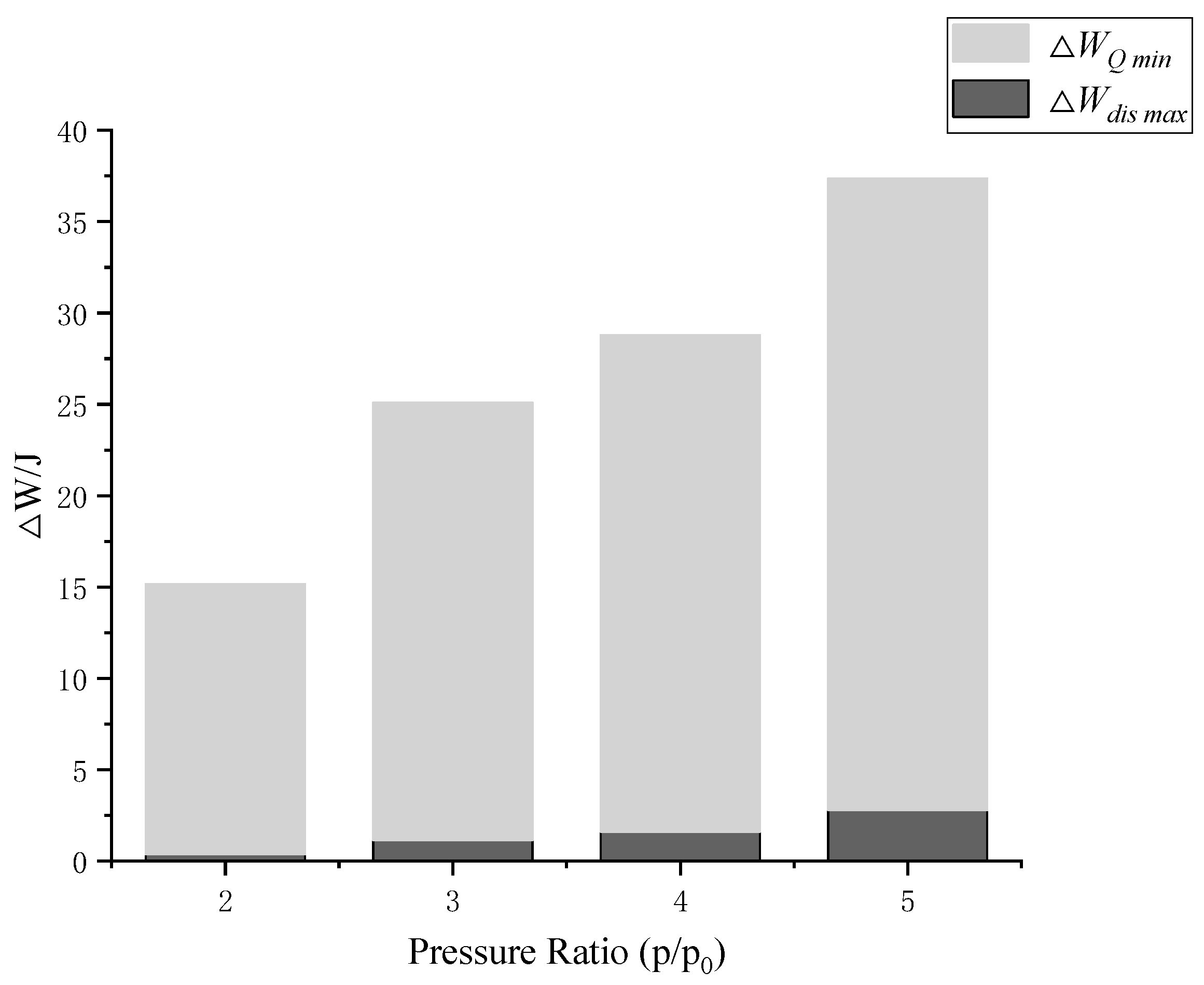
While, the lower limit of △WQ can be inferred to verify that heat transfer dominates the work reduction. As reduction of compression work is determined, △WQ reaches a minimum when △Wdis is maximum. For the upper limit of △Wdis, compression with conventional piston is under adiabatic condition, while compression with isothermal piston is under isothermal condition. That means T2 can be figured out as adiabatic temperature and T1 keeps constant as initial. The maximum of △Wdis can be determined as Equation (11), and the minimum of △WQ can be determined as Equation (12).
Figure 13 presents the work reduction of such two contrast experiments. It can be seen that △WQmin accounts for most of the △W. At pressure ratio of 5, total compression work is reduced by 19.3%, 7.4% of the reduction is caused by △Wdis max, while △WQmin accounts for 92.6% of it. That means at least 92.6% of the saved compression work is caused by increased heat transfer. Here it can be concluded that heat transfer dominates the compression work reduction.
5. Conclusions
A piston structure was proposed to approach isothermal conditions for compression. It relies on maximizing the heat exchange area of air, allowing more heat to be removed during the compression process, and then lowering the work required to compress the gas. A porous medium that can travel along the piston is inserted into the compression chamber. Then heat in the porous media can be conducted away to water.
Interference of air dissolution was added to the results. Both the mass loss of air and heat transfer can lead to the reduction of pressure and compression work. The air loss of mass can be estimated with Henry’s law. The compression work reduction influenced by dissolution is regarded as work for air exhaust. It can be determined by ideal gas law.
Contrast experiments were performed to validate the effectiveness of the devised piston structure that heat transfer dominates the compression work reduction. Though exact temperature is uncertain, the minimum effectiveness of heat transfer of such proposed isothermal piston structure can be confirmed. At pressure ratio of 5, among 19.3% of the reduced compression work, heat transfer accounts to at least 92.6%, and the amount to dissolution is 7.4% for maximum. Due to the uncertainty of temperature, this qualitatively analyzed the compressed work reduction by heat transfer compared with mass loss by dissolution.
While results presented in this work proves the effectiveness of the proposed piston structure to approach isothermal conditions, work to overcome frictional forces is not included yet. Frictional forces may cause extra work consumption. Modified experiments should be performed to measure the frictional forces. Air dissolution is a disadvantage of the proposed isothermal piston structure as mass loss of compressed air. Energy recycling from the dissolved air when it comes out from the liquid should be investigated.
Author Contributions
W.X.; investigation, X.W.; resources, M.C.; writing—original draft preparation, T.R.; writing—review and editing, M.L.
Funding
This research was funded by National Natural Science Foundation of China and Fundamental Research Funds for Central Universities, grant number 51605013 and 51875012.
Conflicts of Interest
The authors declare no conflict of interest.
Nomenclature
| p | Pressure of air (Pa) |
| V | Volume (m3) |
| m | Mass (kg) |
| ρ | Density (kg/m3) |
| T | Temperature (K) |
| R | Gas constant (287 J·kg−1·K−1) |
| Q | Heat (J) |
| U | Internal energy (J) |
| W | Compression work (J) |
| ΔW | Reduction in compression work (J) |
| ΔWdis | Reduction in compression work related to dissolution (J) |
| ΔWQ | Reduction in compression work related to heat transfer (J) |
| c | Concentration of air dissolved in water (kg/m3) |
| Hcp | Henry’s law constant (kg/m3Pa−1) |
| ε | Porosity (%) |
| Sv | Specific surface area of porous medium (m−1) |
| Sp | Cross-sectional area of piston (m2) |
| x | Displacement of piston (m) |
| L | Length of compression chamber (m) |
| D | Diameter of piston (m) |
| Subscripts | |
| 0 | Initial condition |
| a | Atmosphere: (pa = 101,300 Pa; Ta = 293 K) |
| air | Air |
| iso | Isothermal condition |
| adi | Adiabatic condition |
| dis | Dissolution |
| water | Water in compression chamber |
| wall | Wall of compression chamber |
| por | Porous medium |
References
- Shi, Y.; Cai, M.; Xu, W.; Wang, Y. Methods to Evaluate and Measure Power of Pneumatic System and Their Applications. Chin. J. Mech. Eng. 2019, 32, 42. [Google Scholar] [CrossRef] [Green Version]
- Budt, M.; Wolf, D.; Span, R.; Yan, J. A review on compressed air energy storage: Basic principles, past milestones and recent developments. Appl. Energy 2016, 170, 250–268. [Google Scholar] [CrossRef]
- Zaloudek, F.; Reilly, R. An Assessment of Second-Generation Compressed-Air Energy-Storage Concepts; Battelle Pacific Northwest Labs.: Richland, WA, USA, 1982.
- Herbst, C.; Hoffeins, H.; Stys, Z. Huntorf 290 MW air storage system energy transfer (ASSET) plant design, construction and commissioning. In Proceedings of the Präsentation auf American Power Conference, Chicago, IL, USA, 1 January 1978; Volume 17. [Google Scholar]
- Chatzivasileiadi, A.; Ampatzi, E.; Knight, I. Characteristics of electrical energy storage technologies and their applications in buildings. Renew. Sustain. Energy Rev. 2013, 25, 814–830. [Google Scholar] [CrossRef]
- Power, R. Adele–Adiabatic Compressed-Air Energy Storage for Electricity Supply; RWE Power AG, Essen/Koln: Köln, Germany, 2010; pp. 953–956. [Google Scholar]
- Black & Veatch. Cost and Performance Data for Power Generation Technologies; Quintel Intelligence: Amsterdam, The Netherlands, 2012. [Google Scholar]
- Succar, S.; Williams, R.H. Compressed air energy storage: Theory, resources, and applications for wind power. Princet. Environ. Inst. Rep. 2008, 8, 81. [Google Scholar]
- Sedlacek, R.; Rokosz, W.; Kahn, S.; Joffre, G.; Eyck, T.P.; Odevall, C.; Noteboom, H.; Ivanov, R.; Kunev, V.; Radu, G. Study on Underground Gas Storage in Europe and Central Asia. Technical Report for United Nations Economic Commission for Europe. Available online: http://0-refhub-elsevier-com.brum.beds.ac.uk/S3060-5422(13)01067-0/sref5 (accessed on 29 September 2019).
- Pimm, A.J.; Garvey, S.D.; de Jong, M. Design and testing of energy bags for underwater compressed air energy storage. Energy 2014, 66, 496–508. [Google Scholar] [CrossRef]
- Lemofouet-Gatsi, S. Investigation and optimisation of hybrid electricity storage systems based on compressed air and supercapacitors. EPFL 2006. [Google Scholar] [CrossRef]
- Wieberdink, J.; Li, P.Y.; Simon, T.W.; van de Ven, J.D. Effects of porous media insert on the efficiency and power density of a high pressure (210 bar) liquid piston air compressor/expander—An experimental study. Appl. Energy 2018, 212, 1025–1037. [Google Scholar] [CrossRef]
- Wieberdink, J.H. Increasing Efficiency and Power Density of a Liquid Piston Air Compressor/Expander with Porous Media Heat Transfer Elements. Master’s Thesis, University of Minnesota, Minneapolis, MN, USA, 2014. [Google Scholar]
- Yan, B.; Wieberdink, J.; Shirazi, F.; Li, P.Y.; Simon, T.W.; van de Ven, J.D. Experimental study of heat transfer enhancement in a liquid piston compressor/expander using porous media inserts. Appl. Energy 2015, 154, 40–50. [Google Scholar] [CrossRef]
- Van de Ven, J.D.; Li, P.Y. Liquid piston gas compression. Appl. Energy 2009, 86, 2183–2191. [Google Scholar] [CrossRef]
- Troy, M.; Alex, B.; Dax, K. Icaes Innovation: Foam-Based Heat Exchange. 2013. Available online: http://www.sustainx.com (accessed on 27 November 2017).
- Saadat, M.; Li, P.Y. Combined Optimal Design and Control of a Near Isothermal Liquid Piston Air Compressor/Expander for a Compressed Air Energy Storage (CAES) System for Wind Turbines. In Proceedings of the ASME DSCC, Columbus, OH, USA, 28–30 October 2015. [Google Scholar]
- Jia, G.; Xu, W.; Cai, M.; Shi, Y. Micron-sized water spray-cooled quasi-isothermal compression for compressed air energy storage. Exp. Therm. Fluid Sci. 2018, 96, 470–481. [Google Scholar]
- Ashby, M.F.; Lu, T. Metal foams: A survey. Sci. China 2003, 46, 521–532. [Google Scholar] [CrossRef]
- Schweitzer, P.H.; Szebehely, V.G. Gas Evolution in Liquids and Cavitation. J. Appl. Phys. 1950, 21, 1218–1224. [Google Scholar] [CrossRef]
- Sander, R. Compilation of Henry’s law constants, version 3.99. Atmos. Chem. Phy. 2015, 15, 4399–4981. [Google Scholar] [CrossRef]
- The Engineering ToolBox. Available online: https://www.engineeringtoolbox.com/air-solubility-water-d_639.html (accessed on 13 March 2019).
Figure 1.
p-V diagram.

Figure 2.
Schematics of the adiabatic compressed air energy storage (CAES) system.

Figure 3.
Schematics of the isothermal CAES system.

Figure 4.
Isothermal principle.

Figure 5.
Schematic of the experimental platform.

Figure 6.
Picture of the experimental platform.

Figure 7.
Porous medium: foam copper.

Figure 8.
Solubility at different pressures.

Figure 9.
p-V diagram for adiabatic condition.

Figure 10.
Piston displacement.

Figure 11.
p-V diagram for the contrast compression experiments.

Figure 12.
Compression work (not including work to overcome frictional forces).

Figure 13.
Reduction of compression work.


Table 1.
Parameters of experimental equipment.
| Equipment | Company/Serial No. | Parameter |
|---|---|---|
| Compression chamber | - | Φ100 mm, L200 mm |
| Drive cylinder | SMC/CDQ2B100-100D | Φ100 mm, L120 mm |
| Pressure regulator | SMC/AF30-03 | 0.1–1.0 MPa |
| Solenoid valve | SMC/ SY5140-5L-02 < 0.15–0.7 MPa > | Frequency < 20 Hz |
| Displacement sensor | SiFang | Resolution: 40 μm/pulse Range: 0–1 m |
| Pressure sensor | KELLERPR/25 | Range: −1–10 bar Accuracy: ±0.2% FS Frequency < 5 kHz |
Table 2.
Experimental parameters.
| Parameter Name | Symbol | Parameter |
|---|---|---|
| Diameter of the piston | D/m | 0.1 |
| Length of the compression chamber | L/m | 0.12 |
| Cross-sectional area of the piston | Sp/m2 | 7.8 × 10⁻³ |
| Compression ratio | V0/V | 1–5 |
| Rotational speed | n/rpm | 5–90 |
| Porosity of the foam copper | ε/% | 0.92 |
| Specific surface area of the foam copper | Sv/m−1 | 298,000 |
| Volume of the foam copper | Vpor/cm3 | 30 |
| Volume of the water | Vwater/L | 0.775 |
| Initial volume of the air | V0/L | 0.635 |
| Initial temperature of the air | T0/K | 293 |
| Initial pressure of the air | p0/Pa | (0.103–0.107) × 106 |
© 2019 by the authors. Licensee MDPI, Basel, Switzerland. This article is an open access article distributed under the terms and conditions of the Creative Commons Attribution (CC BY) license (http://creativecommons.org/licenses/by/4.0/).
Share and Cite
MDPI and ACS Style
Ren, T.; Xu, W.; Cai, M.; Wang, X.; Li, M. Experiments on Air Compression with an Isothermal Piston for Energy Storage. Energies 2019, 12, 3730. https://0-doi-org.brum.beds.ac.uk/10.3390/en12193730
AMA Style
Ren T, Xu W, Cai M, Wang X, Li M. Experiments on Air Compression with an Isothermal Piston for Energy Storage. Energies. 2019; 12(19):3730. https://0-doi-org.brum.beds.ac.uk/10.3390/en12193730
Chicago/Turabian StyleRen, Teng, Weiqing Xu, Maolin Cai, Xiaoshuang Wang, and Minghan Li. 2019. "Experiments on Air Compression with an Isothermal Piston for Energy Storage" Energies 12, no. 19: 3730. https://0-doi-org.brum.beds.ac.uk/10.3390/en12193730
Note that from the first issue of 2016, this journal uses article numbers instead of page numbers. See further details here.