Implementation of Dual-Circuit System for Additional Power Supply Based on Photovoltaic Converters for Electric Vehicles †


Federal State Unitary Enterprise “Central Scientific Research Automobile and Automotive Engines Institute” (FSUE “NAMI”), 125438 Moscow, Russia
*
Author to whom correspondence should be addressed.
†
This paper is an extended version of our paper published in the International Automobile Scientific Forum (IASF-2018), Intelligent Transport System Technologies and Components, Moscow, Russia, 18–19 October 2018.
Energies 2019, 12(20), 4010; https://0-doi-org.brum.beds.ac.uk/10.3390/en12204010
Submission received: 17 September 2019
/
Revised: 17 October 2019
/
Accepted: 18 October 2019
/
Published: 22 October 2019
(This article belongs to the Special Issue Selected papers from the British Council Researcher Links UK-Russia Workshop "Scientific and Technical Grounds of Future Low-Carbon Propulsion")
Abstract
:The article presents a process of designing the photovoltaic (PHV) converters system for an electric vehicle, shows the scheme of photovoltaic converters usage, the results of electric vehicle motion modeling with photovoltaic converters, and the results of road tests of an electric vehicle with an additional power source based on photovoltaic converters. The photovoltaic converters system and low-voltage system of an electric vehicle have a shared low-voltage battery, which allows the implementation of two schemes of electric vehicle power supply. Initially, the aggregate base was selected, then, taking into account the efficiency of each device included in the design of the new electric vehicle, mathematical modeling was carried out and showed good efficiency results of the photovoltaic converters system. Then, the prototype was manufactured and tested. The aggregate base included the battery of photovoltaic converters assembled in a certain way on the vehicle roof, the MPPT (maximum power point tracking) controller, the buffer storage device in the form of a 12 V battery, and the DC (direct current) converter that allows transmitting electricity from the buffer battery to the high-voltage system. Modeling of the electric vehicle motion considered typical operating modes, including energy costs for the operation of assistant systems of the electric vehicle, as well as including the consumption of low-voltage components. The tests were carried out according to the NEDC (New European Driving Cycle). As a result, implementation of photovoltaic converters with 21% efficiency allowed for the power reserve of the electric vehicle to be increased by up to 9%.
1. Introduction
Nowadays, there are a large number of vehicle projects that use solar energy. Some of them use energy in order to increase the power reserve, others use energy for cooling and ventilation of the cabin. However, some of these projects were implemented more than 5 years ago, when the efficiency of PHV (photovoltaic) elements or cells was about 10%. Recently, improvements in the development of PHV elements made it possible to start mass production of PHV elements with efficiencies higher than 20%, and advanced technologies allow us to obtain up to 50% efficiency in laboratory conditions. Also, the motion speed and energy costs for PHV elements were increased, as is clearly seen from NEDC (New European Driving Cycle) and WLTC (Worldwide Harmonized Light Vehicles Test Cycle) comparison.
In the field of development of photovoltaic converters, there have been many discoveries that have gradually led to increases in the efficiency of solar cells, first in the laboratory, and then in real operations. In 2009, the Spectrolab (Boeing International Headquarters, Chicago, Illinois, U.S.) research company developed photovoltaic converters that had 41.6% efficiency [1]. As early as 2011, Solar Junction set a new mark in PHV efficiency in laboratory conditions, as an efficiency of 43.5% was obtained for a 5.5 × 5.5 mm sample, which exceeded the previous achievement by 1.2%. In 2013, Sharp manufactured a three-layer PHV with dimensions of 4 × 4 mm on an indium-gallium-arsenide basis that had an efficiency of 44.4% [2].
In 2013, scientists from Soitec and CEA-Leti (France) together with the Fraunhofer Institute for Solar Energy Systems ISE (Fraunhofer Solar Power Systems) (Germany) developed a PHV that demonstrated up to 46% efficiency in the laboratory [3].
In November 2017, the Rzhanov Institute of Semiconductor physics (IPP), with the support of Ekran PHV, developed a new type of photovoltaic converter that demonstrated higher efficiency, reaching the mark of 50% [4].
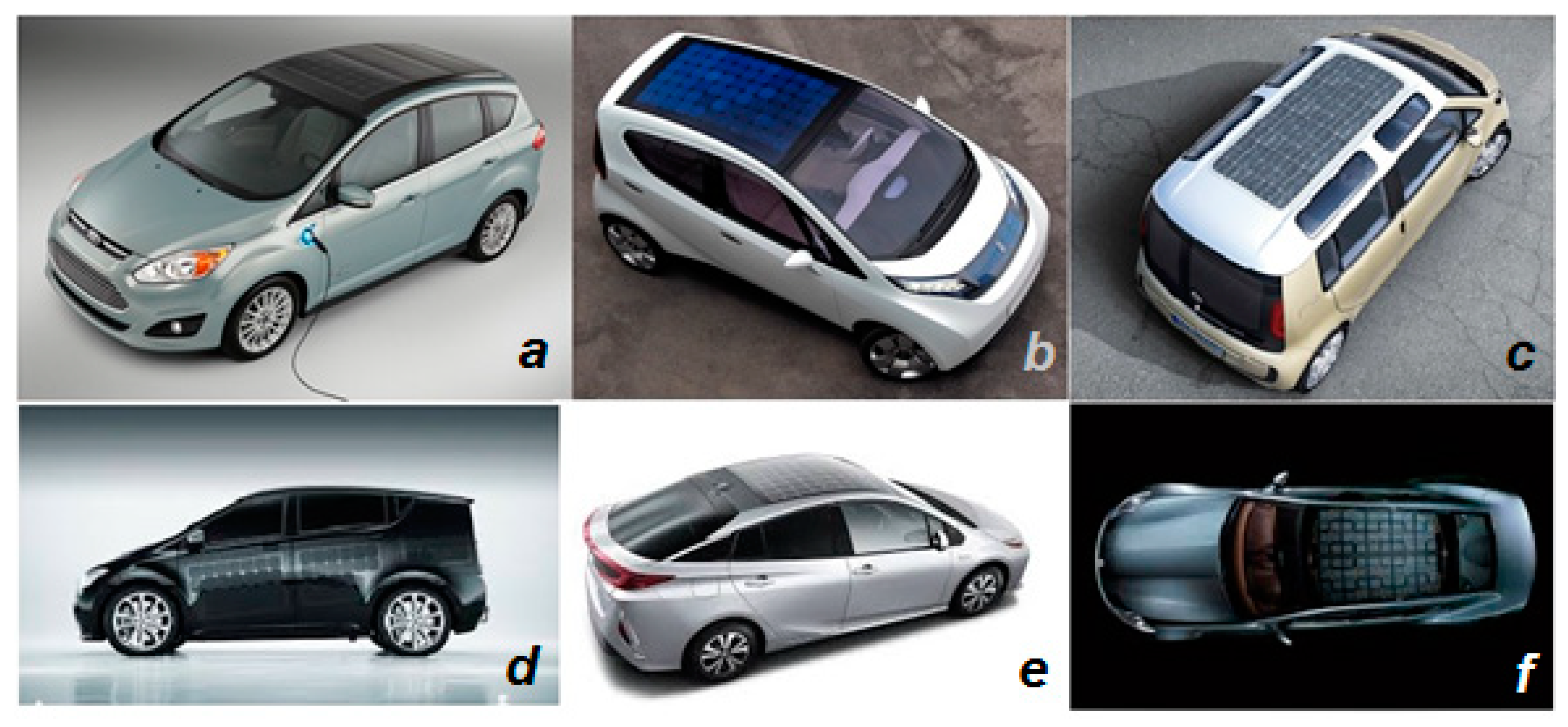
After studying the trends in the development of photovoltaic converters and the fact that their efficiency has already reached 50%, it was decided to study the aspects of integration of the photovoltaic converters in the electric vehicle design and the problems associated with the transmission of electricity from photovoltaic converters to high-voltage batteries in order to increase the mileage of electric vehicles. In an era featuring the struggle to reduce CO2 emissions and efforts to increase the usage of electric vehicles and green energy, many automotive brands around the world have attempted to introduce the use of photovoltaic converters into the design of their vehicles [5,6] (see Figure 1).
2. The Problem of CO2 Emissions
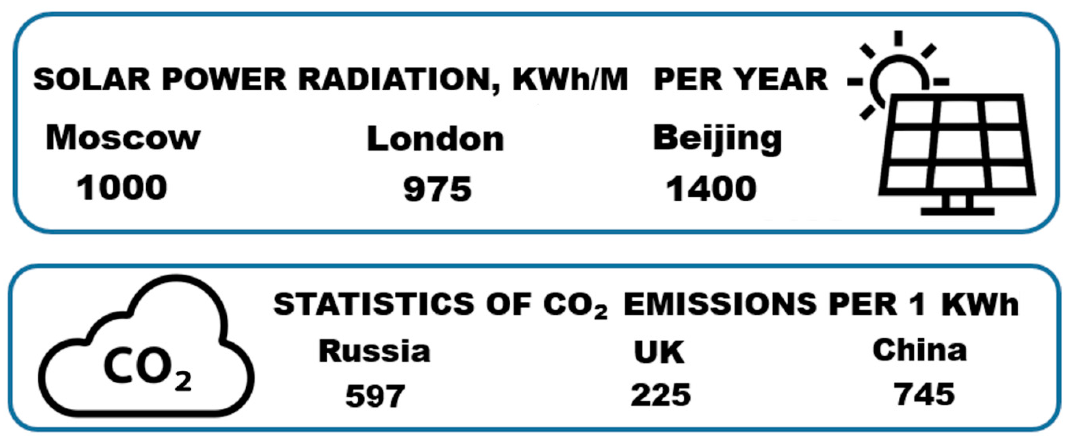
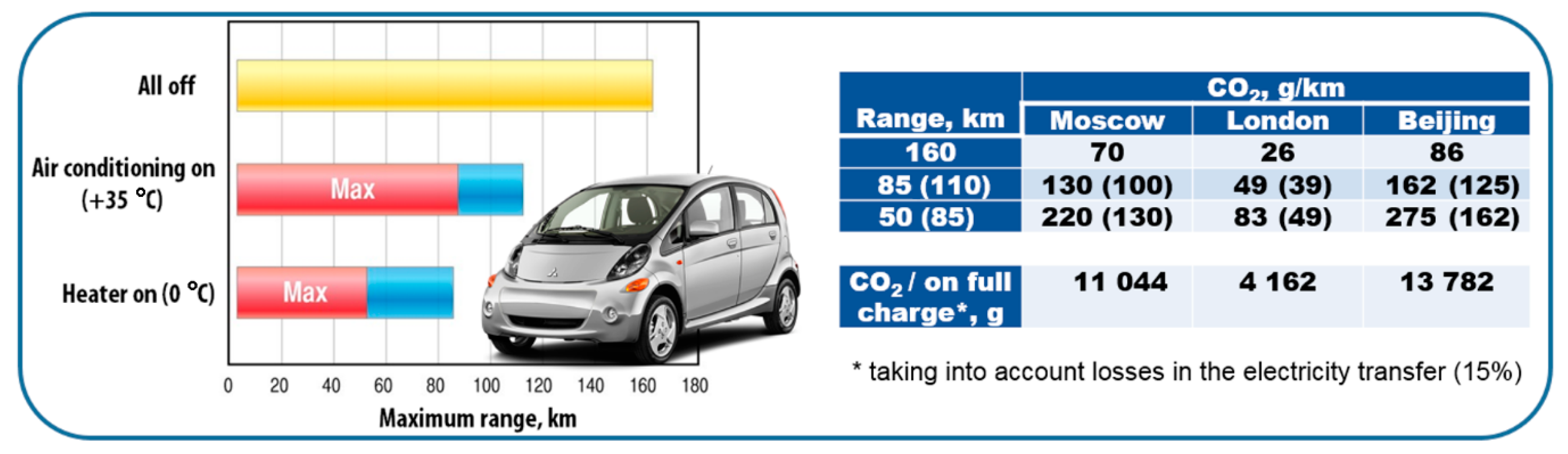
CO2 emissions from electricity generation are different in each country. Figure 2 shows the statistics on CO2 emissions per 1 kWh, as well as power of solar radiation. Based on these data and on the mileage characteristics of the Mitsubishi i-Miev electric vehicle, we can draw conclusions about the indirect CO2 emissions rate per 1 km of this electric vehicle run (see Figure 3), excluding the losses during electric power transmission.
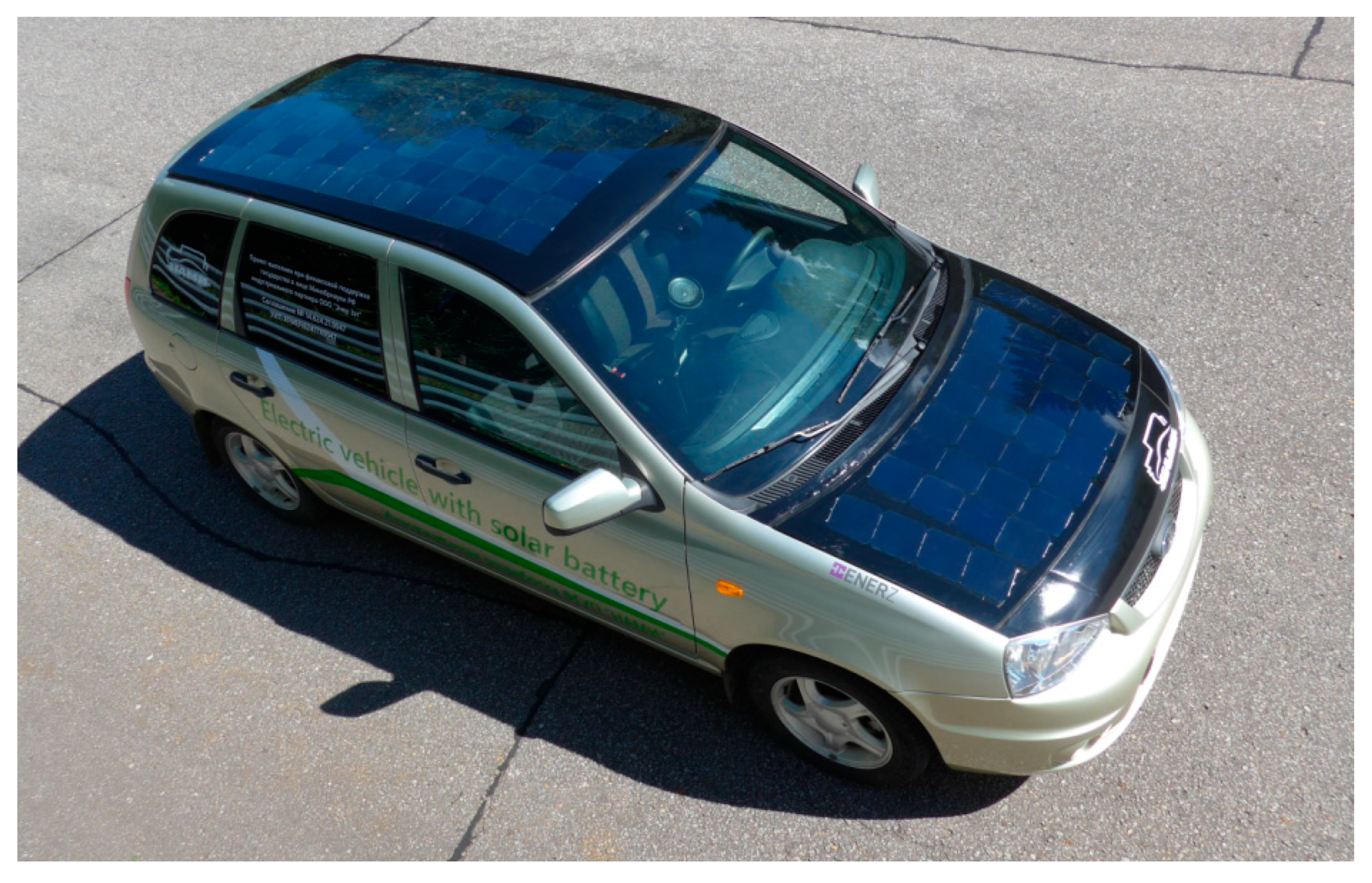
After studying all the negative factors associated with charging the electric vehicles and taking into account the development of photoelectric or photovoltaic converters, it is relevant to equip an electric vehicle with photoelectric converters that are capable of charging a high-voltage battery (HVB). This will help to avoid unnecessary losses in the transmission of electricity and allow for the daily charging of an electric vehicle, even when it is not in use. Within the “Solar Battery” project, an electric vehicle was manufactured with a system of additional energy sources based on PHV elements, including an electric power transmission channel to the HVB, as well as a temperature control system for the main functional units of the electric vehicle (see Figure 4). The main problem to be solved within this research work is how to transfer electricity from photovoltaic converters to high-voltage batteries with minimal losses in order to implement the possibility of autonomous operation of the system of photovoltaic converters and to ensure their performance regardless of external factors. The installation of a photovoltaic converters system shall reduce the dependence of the electric vehicle on electricity that is produced in a traditional way with a large amount of CO2 emissions.
In the first stage of the work, technical requirements were formed, and patent and analytical studies were carried out in the field of electric vehicles with hybrid power units, which also include PHVs. The following were developed: the mathematical model of motion and the method of calculating the traction-dynamic characteristics of the vehicle with additional power sources based on PHV, as well as schematic diagrams and design documentation for the following systems: rechargeable power storage system (RPSS); photovoltaic converter system; and temperature control system RPSS.
3. Development of the Electric Vehicle Energy System
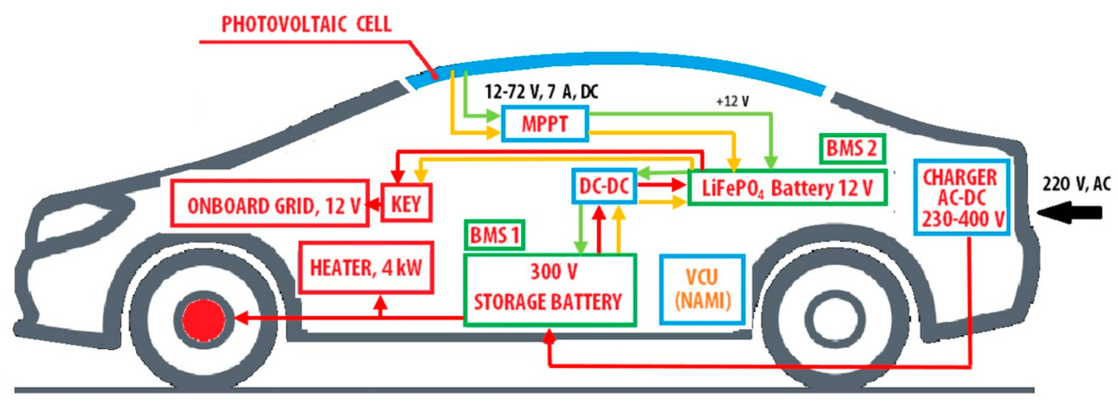
After the stage of analytical studies and after the development of the electric energy converters system arrangement concept, low-voltage and high-voltage systems of the experimental electric vehicle were developed. The photovoltaic converter system shall be integrated into the electric vehicle and shall be able to transmit electricity to both systems (the low-voltage system and the high-voltage system). Thus, a two-circuit system was developed that included only two DC converters. The first ensures the efficient operation of the photovoltaic converter battery, and the second ensures the efficient transmission of electricity between the high-voltage battery and the low-voltage battery. The schematic diagram is shown in Figure 5. The system of photovoltaic converters is implemented for operation in two modes: static (green line) and dynamic (yellow line). The red lines show a traditional scheme of the electric vehicle with AC-DC (alternating current-direct current) Charger.
In the first case, when the electric vehicle is parked, the system charges the low-voltage battery automatically. After the low-voltage battery charge reaches its maximum, the second converter is turned on, which is responsible for charging the high-voltage battery. Both systems include high-voltage and low-voltage Li-ion (LiFePO4) batteries with the BMS (Battery management system). When the minimum allowable voltage in the low-voltage battery is reached, the power transmission stops. This DC converter is capable of transmitting electricity in two directions: from the low-voltage battery to the high-voltage battery and back. The VCU-module (Vehicle control unit) developed by FSUE “NAMI”, provides the operation of both circuits.
While driving the electric vehicle, the circuit works on the following principle: the battery of photovoltaic cells feeds the low-voltage battery that supports the operation of low-voltage electronics. If there is a difference between electricity consumption and production, then the DC converter maintains operation of the low-voltage circuit using the high-voltage battery energy. This solution allows for less use of electricity from the high-voltage battery, which allows the electric vehicle’s mileage to be increased.
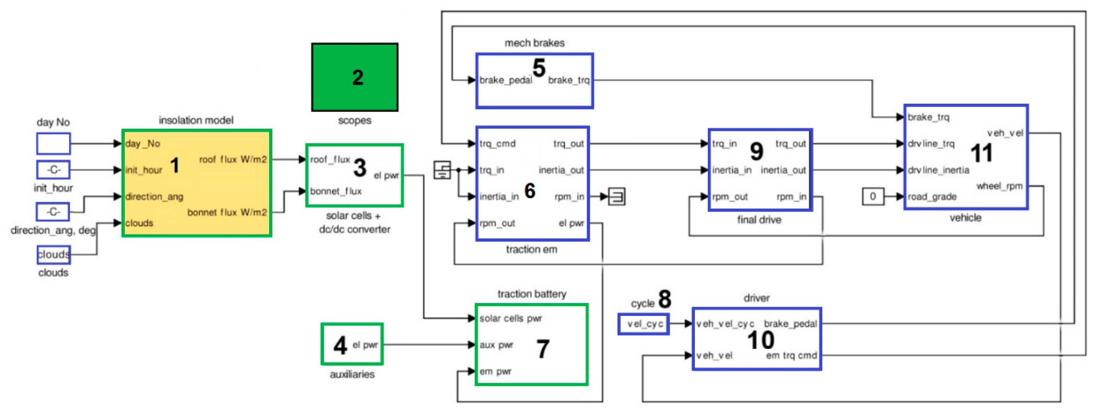
The mathematical description of each element used in the electric vehicle system makes it possible to create a mathematical model of the electric vehicle with a system of photovoltaic converters, which was implemented in the Simulink environment and allowed for the motion to be simulated according to a certain cycle in different conditions. A detailed mathematical description of each component of the experimental electric vehicle with the system of photovoltaic converters was developed in Federal State Unitary Enterprise (FSUE) “NAMI” and published earlier [7]; the model’s top-level view is shown in Figure 6.
The results of mathematical modeling showed that in different latitudes of the Russian Federation the photovoltaic converters system may provide up to 260 kWh per year of electricity in the northern part of the country (at the latitude of St. Petersburg), up to 280 kWh per year in the central part of the country (at the latitude of Moscow), and up to 380 kWh in the southern part of the country (at the latitude of Sochi and Astrakhan). Taking into account CO2 emissions from electricity generation in the Russian Federation, it can be said that the use of this system in an electric vehicle will help to avoid unnecessary CO2 emissions in the amount of 153,000 to 240,000 grams per year [8] compared with an electric vehicle of a similar class with a standard method of charging [9].
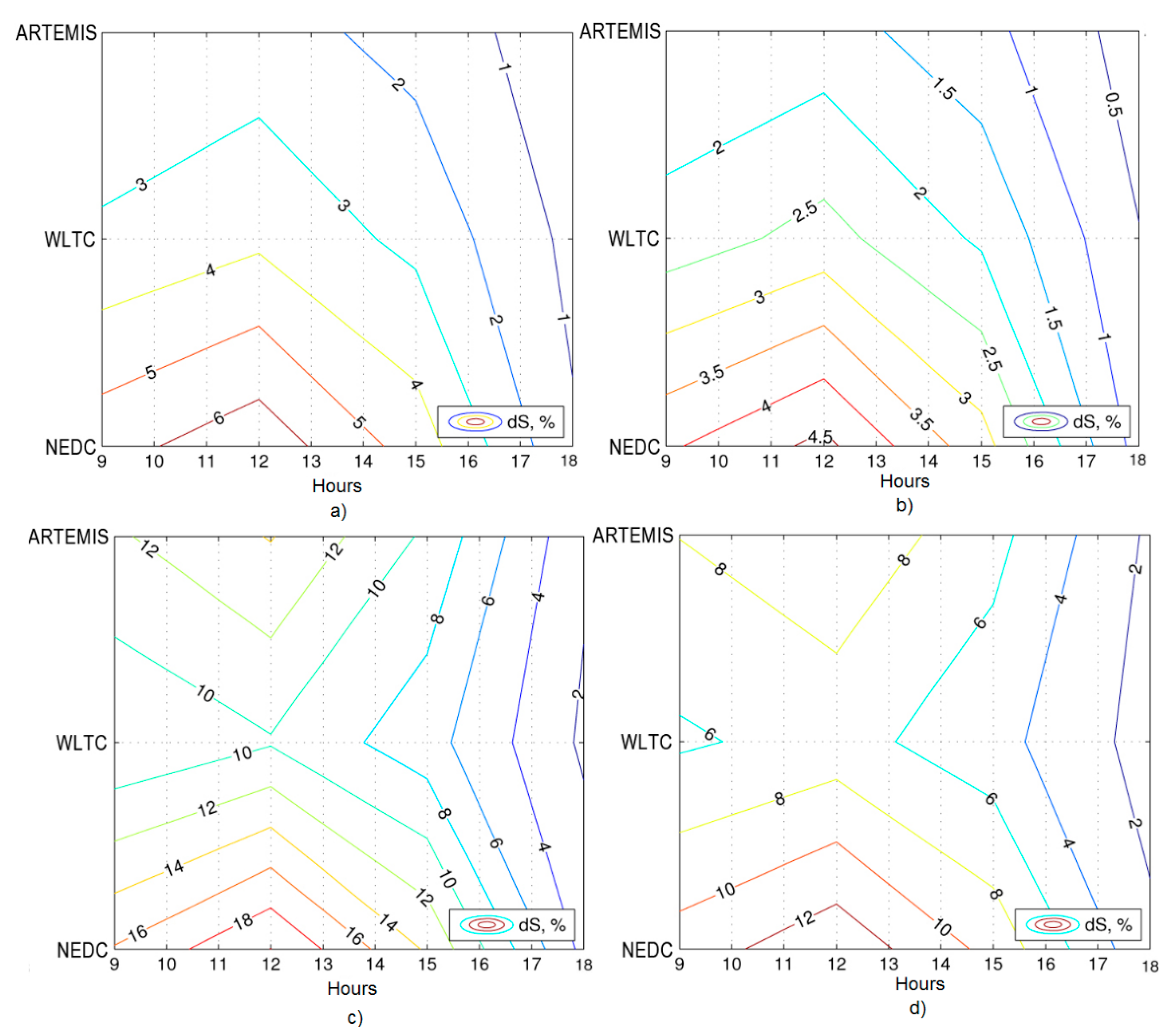
There was also a simulation of motion of the electric vehicle with the system of photovoltaic converters in three cycles: NEDC, WLTC, and ARTEMIS (Assessment and Reliability of Transport Emission Models and Inventory Systems) (see Figure 7).
The results of computational experiments show that the highest effect from the use of photovoltaic cells can be obtained when operating the electric vehicle in the city. When using two solar cell batteries, up to an 18% mileage increase can be obtained in summer conditions. The most favorable season in terms of the effect of using solar cells is the period from mid-spring to early autumn. In winter, the effect drops to zero.
The effect of mileage increase depends on traffic intensity. With its increase, characteristic of WLTP and ARTEMIS cycles, which reproduce modern road conditions, the advantages of using solar cells are reduced by 5–10% compared to the outdated NEDC cycle, which shows the low dynamics of European traffic of the 1980s. In mixed cycles in summer conditions, the increase in mileage is up to 6%, and in the case of modern cycles with increased traffic dynamics, the effect is reduced to 2.5–3.8%. There is the highest dynamics in the ARTEMIS mixed cycles—the increase in mileage does not exceed 2.5%. In the city cycle (NEDC), the effect of using solar cells can be considered significant—up to 14%. The WLTC cycle is generally less dynamic than ARTEMIS (mileage increased to 3.8%), but in the city cycle, it is not as favorable for the use of solar cells (up to 9.8%).
In the second stage of work, according to the developed methodology, PHV elements with the most similar characteristics for battery manufacture were tested and selected [9]. The control units for operation of the temperature control system and the additional power supply system based on PHV were designed and manufactured, the experimental sample of additional power supply system based on PHV was assembled, the RPSS module with temperature control was developed, the experimental electric vehicle was assembled, the electric temperature control system was assembled in-vehicle, and the software was developed and debugged.
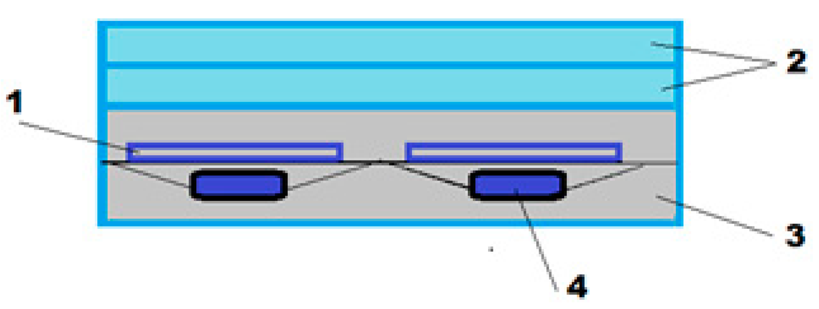
The experience of research teams engaged in the modeling of losses in the transmission of energy from photovoltaic converters to the consumer was also considered [10,11]. Possible losses during the passage of sunlight through various protective coatings were considered. After studying the available literature, the method of airless connection of the photoelectric converter with glass and a white opaque substrate on the back sides was chosen [12]. The vehicle has a PHV system that consists of two batteries with 84 and 36 cells, and has a total area of 1.85 m2. Photovoltaic converters with a set efficiency of 20% were used in the work. The photovoltaic converters were assembled in series in order to obtain the maximum voltage. To protect them against various negative environmental factors, photovoltaic converters were placed under glass with a high light transmission coefficient. The two-component compound Silagerm-2104 (Moscow, Russia) was used to connect the photovoltaic converters. This composition provides protection from contact with metal parts of the body on the rear side, as well as airless connection to the protective glazing (see Figure 8). After assembly, the panels of the PHV system were mounted on the horizontal surfaces of the vehicle.
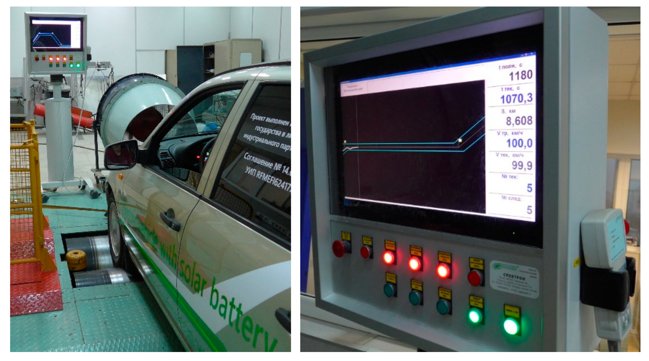
The electric vehicle was tested at the FSUE “NAMI” auto track on a dynamometer road (see Figure 9) and on the stand dynamometer drum in the laboratory (see Figure 10).
Calculation of the force of resistance to the uniform motion of the vehicle is based on its equality to the inertia force acting on the vehicle during its run-down mode (when there is no effect of the power unit or brakes on the vehicle speed). To do this, the vehicle accelerates to a speed no lower than the maximum speed simulated during bench tests (for tests according to the mixed driving cycle of UN Regulation No. 101, this speed is 120 km/h). After its achievement, the transmission selector is moved from the “D” position (forward motion) to the “N” position (neutral gear), and the vehicle moves by inertia to a complete stop. At the same time, its optical sensor records its speed (see Figure 10).
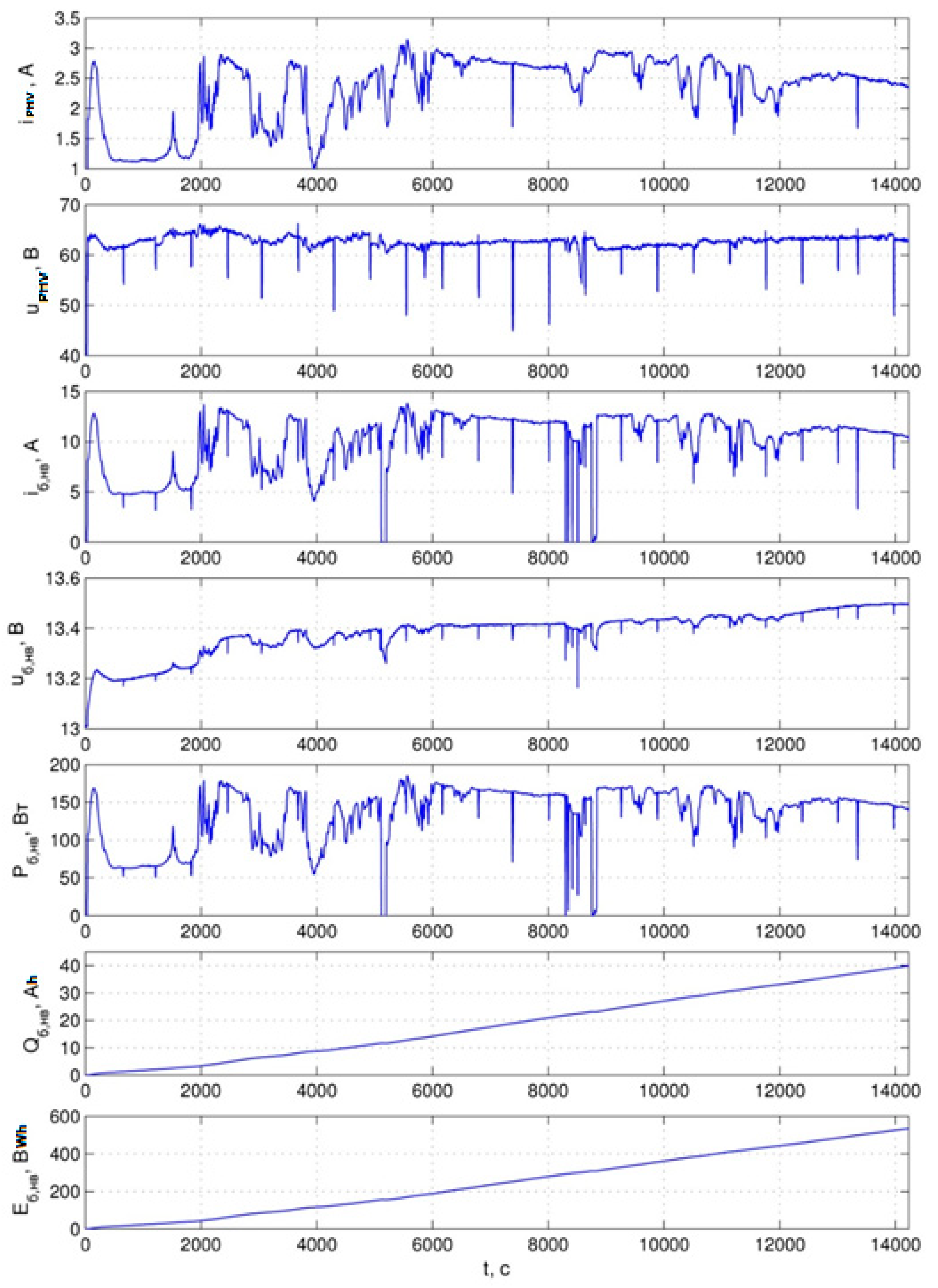
Performance readings of the photovoltaic system were separately recorded in a time interval equal to the running time on the cross-country drums in the NEDC cycle.
According to the test results, it was revealed that (depending on the solar radiation) the system of photoelectric converters can provide up to a 5% increase in mileage in the combined cycle and a 9% increase in mileage in the city cycle. These values were obtained on August 23 in conditions of slight cloudiness (see Table 1). Obviously, when tested on sunnier days in July, larger values in the increase in mileage could be obtained. Performance of the PHV system in the process of charging the buffer storage by means of solar energy is shown in Figure 11.
4. Conclusions
This prototype of an electric vehicle with a PHV showed that with this design of the PHV system it is possible to obtain up to 300 Wh from the area of 1.83 m2, which can not only charge the vehicle during parking, but also be an additional source of energy for domestic purposes with the further growth of PHV efficiency.
Developments in the field of using the vehicle-to-grid protocol (V2G) together with increases in the efficiency of photovoltaic converters will allow the use of electric vehicles as mini power plants, because an electric vehicle is often idling during the day. In the future, an electric vehicle may become a mini power station that will be able to return energy surplus to the network or charge other electric vehicles during idle time.
As a result of road and laboratory (bench) tests conducted at the Testing Centre of FSUE “NAMI”, the following was obtained and confirmed by readings from the developed experimental prototype of the electric vehicle with additional power sources in the form of photovoltaic converters: the maximum mileage on a single charge is 142 km in the city cycle, and the photoelectricity was approximately 200 W per day of testing at average power of the converters.
The increase in mileage due to the use of the system of photovoltaic converters was 5.03% in the mixed driving cycle and 9.1% in the city driving cycle, with an average power of photovoltaic converters of 200 W per hour during testing compared with a similar electric vehicle due to the use of an additional power source on the photovoltaic converters. During the work, it was revealed that the increase in mileage of the electric vehicle when using the system of photovoltaic converters depends on the intensity of traffic. This is confirmed by mathematical modeling when driving in different cycles. Currently, the efficiency of photovoltaic converters reaches 20–22%, which can give an increase in mileage of up to 9% when driving a B-class electric vehicle in the NEDC city cycle in summer.
Author Contributions
Conceptualization, methodology, writing—review and editing, A.K.; validation, formal analysis, R.K.; supervision, project administration, K.K.
Funding
This research was funded by the Ministry of Education and Science of Russia, agreement NO.14.624.21.0047. The unique identifier of the project is RFMEFI62417X0047.
Acknowledgments
The authors would like to express sincere gratitude to the Researcher Links programme of the British Council for the financial support of this publication.
Conflicts of Interest
The funders had no role in the design of the study; in the collection, analyses, or interpretation of data; in the writing of the manuscript, or in the decision to publish the results.
References
- Jones, R.; Hébert, P.; Pien, P.; King, R.; Bhusari, D.; Brandt, R.; Al Taher, O.; Fetzer, C.; Ermer, J.; Boca, A.; et al. Status of 40% Production Efficiency Concentrator Cells at Spectrolab. In Proceedings of the 35th IEEE Photovoltaic Specialists Conference, Honolulu, HI, USA, 20–25 June 2010; Volume 35, pp. 000189–000195. [Google Scholar]
- Ana Belén, C.; Sala, G.; Siefer, G.; Ignacio, A.; Juan, C.M.; Pablo, B.; Andreas, W.B.; Ekins-Daukes, N.J.; Francesco, R.; et al. NGCPV: A New Generation of Concentrator Photovoltaic Cells, Modules and Systems. In Proceedings of the 28th EU PVSEC, Paris, France, 30 September 2013. [Google Scholar]
- Soitec Team Pushes Solar Record to 46%. Available online: http://optics.org/news/5/12/1 (accessed on 21 may 2017).
- Tereshchenko, O.E.; Golyashov, V.A.; Rodionov, A.A.; Chistokhin, I.B.; Kislykh, N.V.; Mironov, V.A.; Aksenov, V.V. Solar energy converters based on multi-junction photoemission solar cells. Sci. Rep. 2017, 23, 16154. [Google Scholar] [CrossRef] [PubMed]
- Bahmutov, S.V.; Karpuhin, K.E. “Clean” cars: Directions of implementation and reached results. J. AAI 2012, 6, 51–54. [Google Scholar]
- Kolbasov, A.F.; Karpukhin, K.E.; Debelov, V.V. Research infrastructure for personal electric transportation: current problems, possible solutions. J. AAI 2017, 2, 36–45. [Google Scholar]
- Kulikov, I.; Karpukhin, K. Model Analysis of Efficiency and Energy Distribution in the Powertrain of an Electric Vehicle Equipped with a Solar Cell Battery; SAE Technical Paper Series; SAE International in United States: Warrendale, PA, USA, 2018. [Google Scholar] [CrossRef]
- Kolbasov, A.; Karpukhin, K.; Terenchenko, A.; Kavalchuk, I. Concept of intellectual charging system for electrical and plug-in hybrid vehicles in Russian Federation. IOP Conf. Ser. Mater. Sci. Eng. 2018, 315, 012013. [Google Scholar] [CrossRef]
- Kolbasov, A.F.; Karpukhin, K.E.; Terenchenko, A.S.; Girutskiy, O.I. Efficiency of photoelectric converters intellectual system application on ground electric transport. IOP Conf. Ser. Mater. Sci. Eng. 2019, 534, 012011. [Google Scholar] [CrossRef]
- Haeyoon, J.; MiYeon, S.; Sanghak, K.A. Development of Energy Management System with Semi-Transparent Solar Roof and Off-Cycle Credit Test Methodology for Solar Power Assisted Automobile. SAE Int. J. Commer. Veh. 2017, 10, 170–177. [Google Scholar] [CrossRef]
- Gibson, T.L.; Kelly, N.A. Solar photovoltaic charging of lithium-ion batteries. J. Power Sources 2010, 195, 3928–3932. [Google Scholar] [CrossRef]
- Koichi, G.; Takahiro, H.; Tatsuya, M.; Daisuke, S. Development Solar Charging System of Vehicle. SAE Int. J. Passeng. Cars Electron. Electr. Syst. 2017, 10, 353–358. [Google Scholar] [CrossRef]
Figure 1.
Vehicles with photovoltaic (PHV) battery: (a) Ford C-MAX Solar Energy concept; (b) Pininfarina B Zero; (c) Volkswagen Space Up Blue (hydrogen-powered); (d) Sono Sion electric vehicle; (e) Solar Roof as an option that Toyota offers to Prius and Auris hybrids; (f) Fisker Karma hybrid vehicle.

Figure 2.
Statistics for solar power radiation and CO2 emissions per 1 kWh of solar power produced.

Figure 3.
Recalculation of electricity consumption by an electric vehicle to the CO2 emissions.

Figure 4.
General view of the electric vehicle with PHV designed and manufactured in Federal State Unitary Enterprise (FSUE) “NAMI”.
Figure 4.
General view of the electric vehicle with PHV designed and manufactured in Federal State Unitary Enterprise (FSUE) “NAMI”.

Figure 5.
Scheme of the dual-circuit system of photovoltaic converters.

Figure 6.
Electric vehicle model with the photovoltaic converters battery in Simulink (upper level of the model). Subsystem 1 creates two signals: energy density on the roof surface and on the hood surface; subsystem 2 contains different variables. Subsystem 3 contains the energy conversion model. Subsystem 4 describes the energy consumption of the low-voltage system. Subsystem 5 contains the service brake system model. Subsystem 6 is the electric motor model. Subsystem 7 is the high-voltage battery. Subsystem 9 is the gearbox model. Subsystem 8 and 10 are submodels of the electric vehicle speed control system. Subsystem 11 allows the forces of resistance to linear motion of the electric vehicle to be calculated.

Figure 7.
Calculated increase in electric vehicle mileage depending on the time of day and driving cycle. Day 196 (July). Mixed cycles: (a) clear sky; (b) cloudy sky. City cycles: (c) clear sky; (d) cloudy sky.
Figure 7.
Calculated increase in electric vehicle mileage depending on the time of day and driving cycle. Day 196 (July). Mixed cycles: (a) clear sky; (b) cloudy sky. City cycles: (c) clear sky; (d) cloudy sky.

Figure 8.
Photovoltaic converters system diagram (section): 1—PHV; 2—protective glazing; 3—filler compound; 4—bypass diode.
Figure 8.
Photovoltaic converters system diagram (section): 1—PHV; 2—protective glazing; 3—filler compound; 4—bypass diode.

Figure 9.
Testing the electric vehicles with the PHV system on the dynamometer road.

Figure 10.
Laboratory tests of the developed electric vehicle (on the left: test at the bench with running drums in the driving cycle mode; on the right: speed monitor).
Figure 10.
Laboratory tests of the developed electric vehicle (on the left: test at the bench with running drums in the driving cycle mode; on the right: speed monitor).

Figure 11.
Readings of operation of the PHV system in the process of charging the buffer storage with solar energy.
Figure 11.
Readings of operation of the PHV system in the process of charging the buffer storage with solar energy.


Table 1.
Readings for the increase in mileage due to the use of PHV system obtained as a result of testing the vehicle.
Table 1.
Readings for the increase in mileage due to the use of PHV system obtained as a result of testing the vehicle.
| Driving Cycle | Vehicle without PHV System, S0, km | Vehicle with PHV-System, S1, km | ΔS, km | ΔS, % |
|---|---|---|---|---|
| City | 130.2 | 142.0 | 11.8 | +9.09% |
| Mixed | 124.9 | 131.1 | 6.2 | +5.03% |
© 2019 by the authors. Licensee MDPI, Basel, Switzerland. This article is an open access article distributed under the terms and conditions of the Creative Commons Attribution (CC BY) license (http://creativecommons.org/licenses/by/4.0/).
Share and Cite
MDPI and ACS Style
Kolbasov, A.; Kurmaev, R.; Karpukhin, K. Implementation of Dual-Circuit System for Additional Power Supply Based on Photovoltaic Converters for Electric Vehicles. Energies 2019, 12, 4010. https://0-doi-org.brum.beds.ac.uk/10.3390/en12204010
AMA Style
Kolbasov A, Kurmaev R, Karpukhin K. Implementation of Dual-Circuit System for Additional Power Supply Based on Photovoltaic Converters for Electric Vehicles. Energies. 2019; 12(20):4010. https://0-doi-org.brum.beds.ac.uk/10.3390/en12204010
Chicago/Turabian StyleKolbasov, Alexey, Rinat Kurmaev, and Kirill Karpukhin. 2019. "Implementation of Dual-Circuit System for Additional Power Supply Based on Photovoltaic Converters for Electric Vehicles" Energies 12, no. 20: 4010. https://0-doi-org.brum.beds.ac.uk/10.3390/en12204010
Note that from the first issue of 2016, this journal uses article numbers instead of page numbers. See further details here.