Article

Traffic-Condition-Prediction-Based HMA-FIS Energy-Management Strategy for Fuel-Cell Electric Vehicles

1
Sino-Dutch Mechatronics Engineering Department, Shanghai Maritime University, Shanghai 201306, China
2
School of Electronics and Information Engineering, Tongji University, Shanghai 201804, China
3
Hangzhou Zhongheng Power Cloud Technology Co., Ltd, Hangzhou 310053, China
4
IETR-UMR CNRS 6164, l’Universite de Nantes/Polytech Nantes, 44300 Nantes, France
5
IREENA, l’Universite de Nantes/Polytech Nantes, 44602 Nantes, France
*
Author to whom correspondence should be addressed.
These authors contributed equally to this work.
Submission received: 2 October 2019 / Revised: 1 November 2019 / Accepted: 18 November 2019 / Published: 21 November 2019
(This article belongs to the Section E: Electric Vehicles)

Abstract

:
In the field of Fuel Cell Electric Vehicles (FCEVs), a fuel-cell stack usually works together with a battery to improve powertrain performance. In this hybrid-power system, an Energy Management Strategy (EMS) is essential to configure the hybrid-power sources to provide sufficient energy for driving the FCEV in different traffic conditions. The EMS determines the overall performance of the power supply system; accordingly, EMS research has important theoretical significance and application values on the improvement of energy-utilization efficiency and the serviceability of vehicles’ hybrid-power sources. To overcome the deficiency of apparent filtering lag and improve the adaptability of an EMS to different traffic conditions, this paper proposes a novel EMS based on traffic-condition predictions, frequency decoupling and a Fuzzy Inference System (FIS). An Artificial Neural Network (ANN) was designed to predict traffic conditions according to the vehicle’s running parameters; then, a Hull Moving Average (HMA) algorithm, with filter-window width decided by the prediction result, is introduced to split the demanded power and keep low-frequency components in order to meet the load characteristics of the fuel cell; afterward, an FIS was applied to manage power flows of the FCEV’s hybrid-power sources and maintain the State of Change (SoC) of the battery in a predefined range. Finally, an FCEV simulation platform was built with MATLAB/Simulink and comparison simulations were carried out with the standard test cycle of the Worldwide harmonized Light vehicle Test Procedures (WLTPs). Simulation results showed that the proposed EMS could efficiently coordinate the hybrid-power sources and support the FCEV in following the reference speed with negligible control errors and sufficient power supply; the SoC of the battery was also maintained with good adaptability in different driving conditions.

Graphical Abstract

1. Introduction

Being 3–5 times more energy efficient than conventional internal-combustion engine vehicles, Electric Vehicles (EVs) have been globally expanding at a rapid pace over the last decade to meet the requirements of conventional-fossil-fuel conservation and vehicle-exhaust-emission reduction [1]. According to the report of the International Energy Agency (IEA), in 2018, global electric cars exceeded 5.1 million, and up to 2 million cars were from the previous year [2]. In this huge EV market, different types of EVs are available, mainly including Plug-in Hybrid EVs (PHEVs), full Battery EVs (BEVs), and Fuel Cell EVs (FCEVs) [3].
Compared with a PHEV or a BEV, an FCEV—an EV that uses hydrogen via a fuel cell to power an electric motor—has unique advantages and has attracted much attention from both the research and industry communities [4]. For example, hydrogen contains three times more energy per unit of mass than gasoline, making it very attractive as a transport fuel; an FCEV has zero tailpipe emissions and short refueling time; moreover, a fuel cell could have lower material footprint than lithium batteries [5]. Accordingly, FCEVs are not only considered applicable for light-duty passenger vehicles but are also attractive options for long-distance and heavy-duty ones. Statistical data show that about 4000 fuel-cell electric cars were sold in 2018 to reach a total stock of 11,200 units in the world [5].
Although an FCEV is very attractive for the above characteristics, due to the performance of a fuel cell, its application in EVs still has some deficiencies. Without the health and safety considerations of hydrogen-based fuel and the installation issues of hydrogen-refueling infrastructure for FCEVs, those deficiencies mainly include: (1) a fuel cell has low power density, resulting in the weak acceleration performance of an FCEV; (2) because of activation, ohmic and concentration polarization losses, the output voltage/current characteristic of a fuel cell is quite ’soft,’ resulting in an obvious output-voltage drop with increasing load current; and (3) a fuel cell is not able to recover energy, resulting in vehicle-braking energy loss in applications [6,7,8].
To deal with the above deficiencies, a fuel cell is usually collaborated with a battery to power an FCEV because the battery has higher power density for accelerations and can recover energy from the braking system [9]. For example, the 2019 Toyota FCEV—Mirai—is powered by a fuel-cell stack of 112 kW and an auxiliary driving battery with a maximum electricity output of 9 kW; the battery allows for regenerative braking energy and also assists the EV during high-power demands like acceleration [10].
However, the integration of a battery into an FCEV requires energy management. The purpose of energy management is to improve total system efficiency and protect hybrid-power sources and enhance their serviceability [11]. An effective EMS can improve the driving performance of an FCEV and even product competitiveness. Accordingly, EMSs have been a research hotspot with the development of hybrid-source-powered EVs in recent years.
In an FCEV, an EMS configures the hybrid-power sources to provide sufficient energy for driving the vehicle in different traffic conditions while offering a timely response to address possible fast power changes due to accelerating or braking by dynamically balancing load sharing among power sources [12,13,14].
To realize the energy management of an FCEV, different methodologies can be found from the literature, such as rule-, Frequency Decoupling (FD)-, Fuzzy Inference System (FIS)- and optimization-algorithm-based methods.
The rule-based EMSs are easy to implement and have been widely adopted [15,16,17]. The technique proposed in Reference [15] divides system states into three categories according to the battery’s State of Change (SoC) and determines fuel-cell reference power by the rules according to load power and fuel-cell power constraints. Simulation results showed that this strategy is simple and effective, but the high performance of the battery was not given full consideration. Roumila et al. [16] divided the system into eight states according to battery SoC and load power and defined a reference power of the fuel cell in each state. Simulation results showed the effectiveness of this strategy but the definition of reference power of the fuel cell in each state was empirical.
The basic idea of FD-based methods is to decouple and redistribute the required load power in the frequency domain according to the load characteristics of each power source [18,19,20]. For example, an FD-based method is designed to divide power demand into high- and low-frequency components, and then distributes them to the battery and fuel cell, respectively. Li et al. and Ibrahim et al. proposed a wavelet-transform- and fuzzy-logic-based FD method in which low-positive-frequency components of the required power are distributed to the fuel cell and high-frequency components are distributed to the auxiliary energy source [18,19]. Marzougui et al. used a first-order low-pass filter to separate the required power for the FD but the filtering-hysteresis problem made it difficult for the fuel cell to follow the low-frequency trend of the load power [20]. FD-based methods are intuitive and efficient but the filtering-hysteresis problem and computational complexity are the main limitations. Another disadvantage of this method is that the SoC of the battery is not taken into account.
FIS-based methods manage hybrid-power sources according to formalized-expert experience and fuzzy inference. Because of their robustness and flexibility, many researchers adopted FIS-based strategies for real-time energy management [21,22,23]. Yang et al. designed a two-input/one-output fuzzy-power controller with load current and battery SoC as inputs and fuel-cell reference current as output [24]. Marzougui et al. designed a fuzzy controller by using trapezoidal membership functions to restrain fuel-cell power fluctuations, but simulation results showed that the sensitivity of the designed controller was compromised [8]. A difficulty of FIS-based energy management is parameter configuration. To reduce parameter-design difficulty and enable better control performance, many researchers considered combining other algorithms with FIS such as wavelet–fuzzy strategies [25,26,27]. Another deficiency concerning current research on FIS-based energy management is that simulation models are often simplified for fast simulations, with reduced accuracy [28,29,30].
Optimization-algorithm-based EMSs usually convert an energy-management problem into a solution-searching problem by defining an object function that is normally used to minimize running cost and/or emissions and adopting an iterative algorithm to find the optimized solution satisfying system-constraint conditions [31,32]. This type of energy-management method can calculate optimized power distributions and take them as control reference for different power sources, accordingly resulting in great advantages for fuel economy. Wang et al. designed an object function to minimize hydrogen consumption and calculate the power distribution of fuel cells and lithium batteries [31]. The hydrogen-utilization rate and system efficiency were improved according to simulation results. Nuesch et al. included fuel consumption and the vehicle emission into one object function with different weights, and adopted a transient optimization method to minimize the target and managed the output power of the diesel engine and the battery in a hybrid vehicle. Simulation results showed that this strategy optimizes fuel consumption within various constraints [32]. With this type of method, if the global-optimization solution can be found and used as control reference of hybrid-power sources, the fuel economy can be improved; however, the searching process in the solution space is time-consuming and, accordingly, their applications in real-time scenarios are limited.
From the above analysis, it can be seen that different energy-management methods have their advantages but also shortcomings in FCEV applications. It is easier to apply rule-, FD- and FIS-based methods in real-time situations than global optimization-based methods, but they are not as adaptive and optimal as the latter ones; for an optimization-based method, the searching process in the solution space takes time and this kind of method is not always applicable for real-time applications in an FCEV with lots of dynamics during a driving process. Moreover, another problem of the current research on EMSs of an FCEV is that changes in driving conditions are not fully taken into account in EMS design. In reality, actual traffic conditions are complex and changeable, and EMSs designed with a certain condition may not be usable under all other driving conditions [33].
Considering the main difficulties in the current research of energy-management methods for an FCEV, a novel EMS combining an advanced FD technique and an FIS with a traffic-condition predictor is proposed in this paper for an EV powered by a fuel cell and a battery. The proposed traffic-condition-based HMA-FIS EMS has the advantages of FD/FIS-based methods and does not need complicated calculation; the adaptability of this method can be improved by the contribution of the traffic-condition predictor.
The rest of this paper is organized as follows—the structure and composition of an FCEV, which was taken as the research object of this paper, is described in Section 2. In Section 3, the proposed EMS is presented. To verify the effectiveness of the proposed EMS, a simulation platform of the FCEV with the proposed EMS was built with MATLAB/Simulink in Section 4 and some simulation results are presented with comparisons in the same section. Finally, in Section 5, the conclusion of this paper is made.

2. FCEV Structure and Its Power System

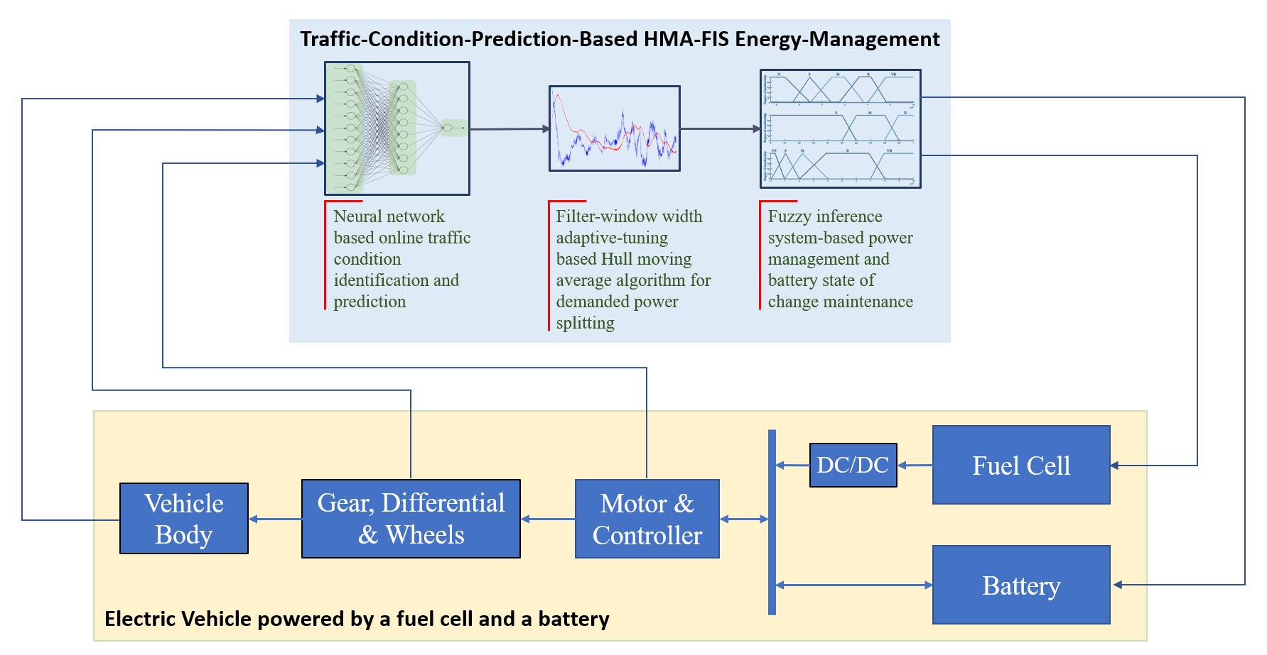
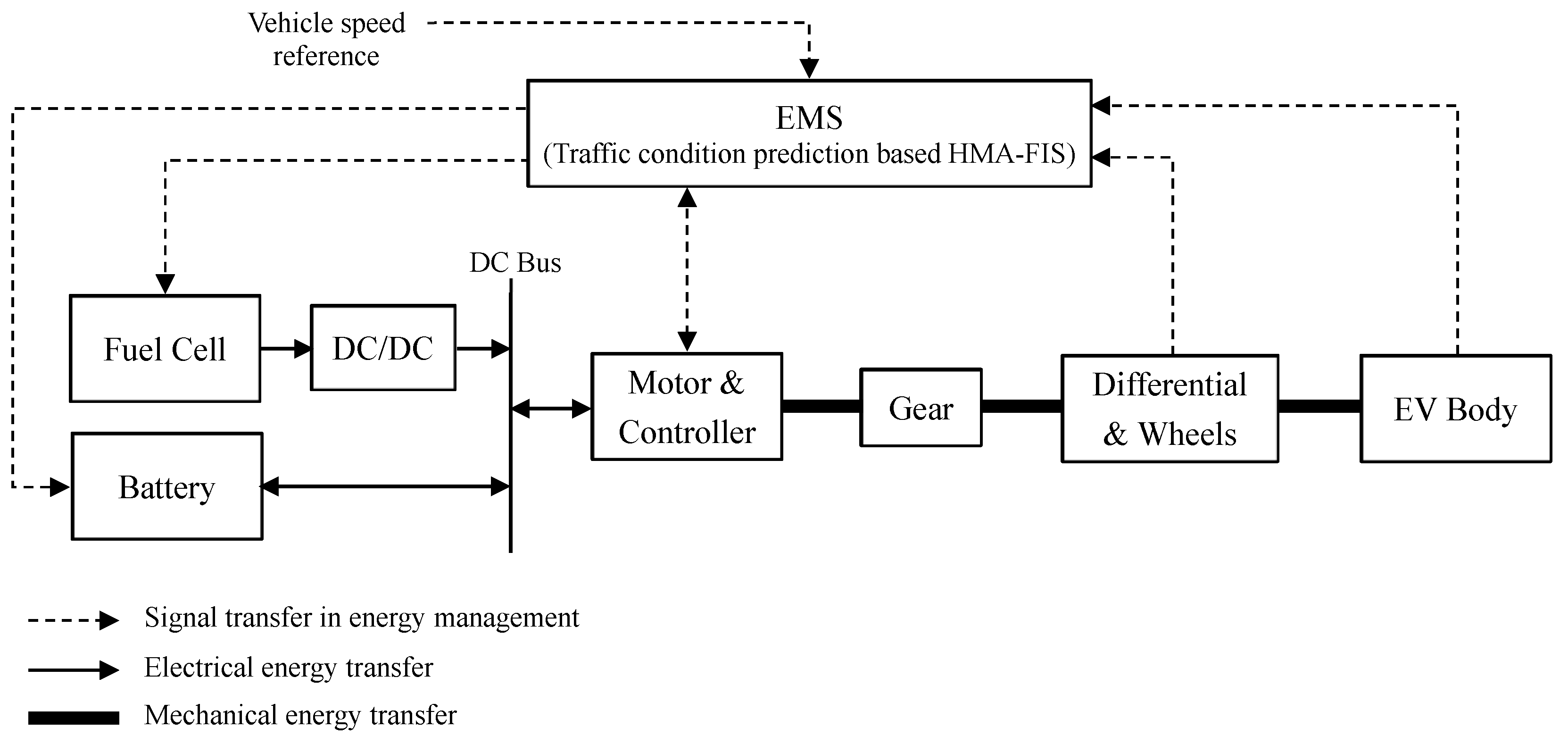
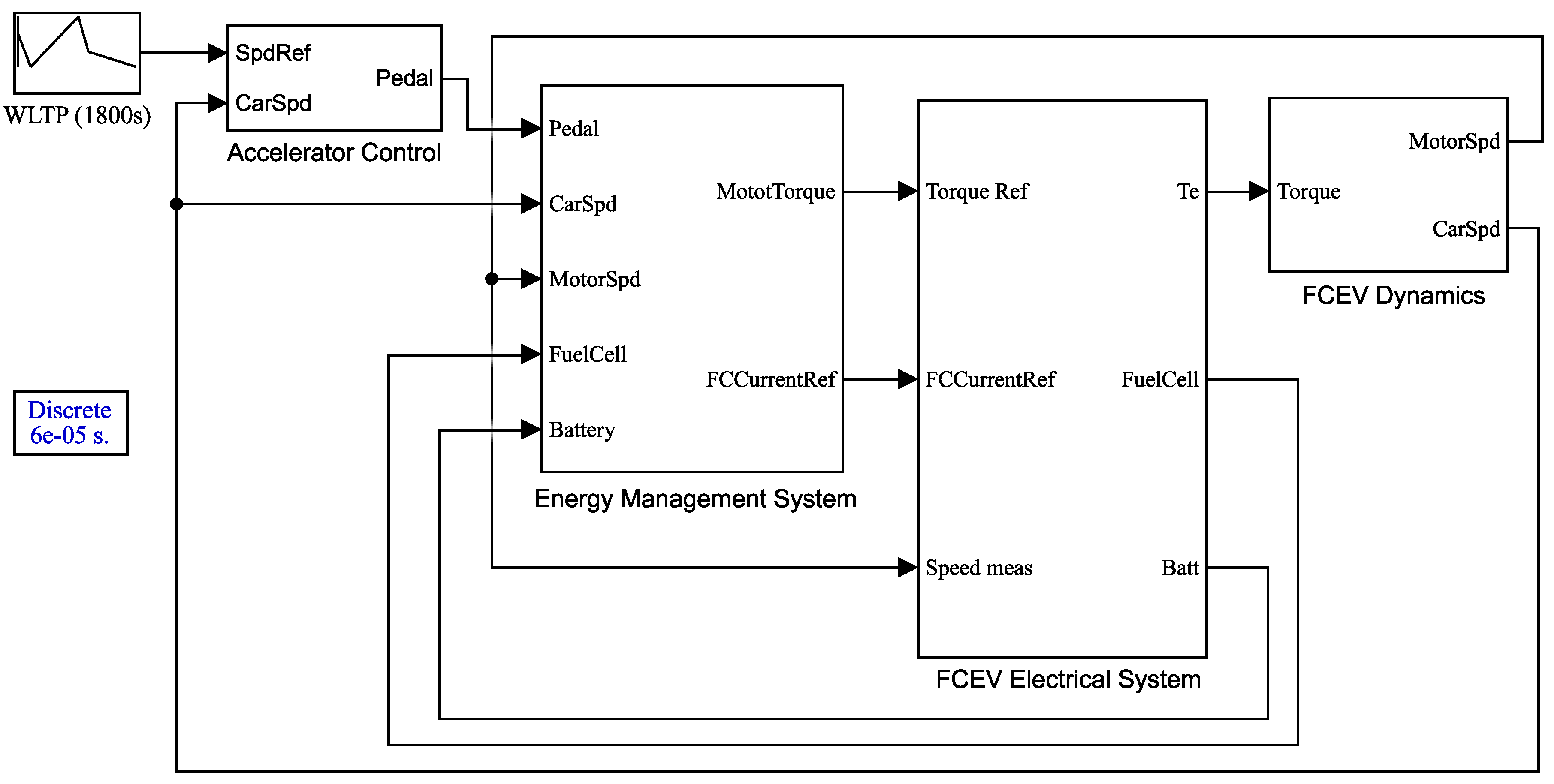
A front-wheel-driven FCEV, including a fuel cell, a battery, a DC/DC converter, a traction motor and its controller, wheels and vehicle body, is taken as the research object in this paper. The structure of this FCEV is shown in Figure 1.
In Figure 1, it can be seen that the fuel cell is connected to the DC bus via a DC/DC converter, which was adopted to convert the output voltage of the fuel cell to the nominal voltage of the DC bus. A battery was used as an auxiliary power source in order to enhance powertrain performance and increase the system’s capability for energy recovery. The battery is directly connected with the DC bus to take advantage of quick charging/discharging performance, and to decrease the size and weight of the hybrid-power supply [34]. The fuel cell and the battery jointly provide the necessary energy through the DC bus to drive the vehicle according to speed reference.
The EMS provides the output-power reference of the fuel cell according to the feedback parameters of the motor, the hybrid-power sources, and the vehicle with the proposed power-management method. The battery delivers the rest of the required power by subtracting the fuel-cell power (controlled by the EMS) from the total demanded power.
A Permanent Magnet Synchronous Motor (PMSM) and a three-phase inverter, powered by the DC bus, were taken as the traction-motor system of the FCEV. The Maximum Torque Per Ampere (MTPA) control principle was adopted to control the motor below the base speed and a flux-weakening method was used to achieve maximum motor speed [35,36,37].
The vehicle dynamic, mainly including gear, differential, wheels and brakes, and EV body, is shown in Figure 1. Since the mechanical transmission system of the vehicle is not the main focus of this paper, the modeling of the vehicle dynamic is not discussed in detail and the related details can be found in References [38,39,40].

3. Traffic-Condition-Prediction-Based HMA-FIS Energy-Management Strategy

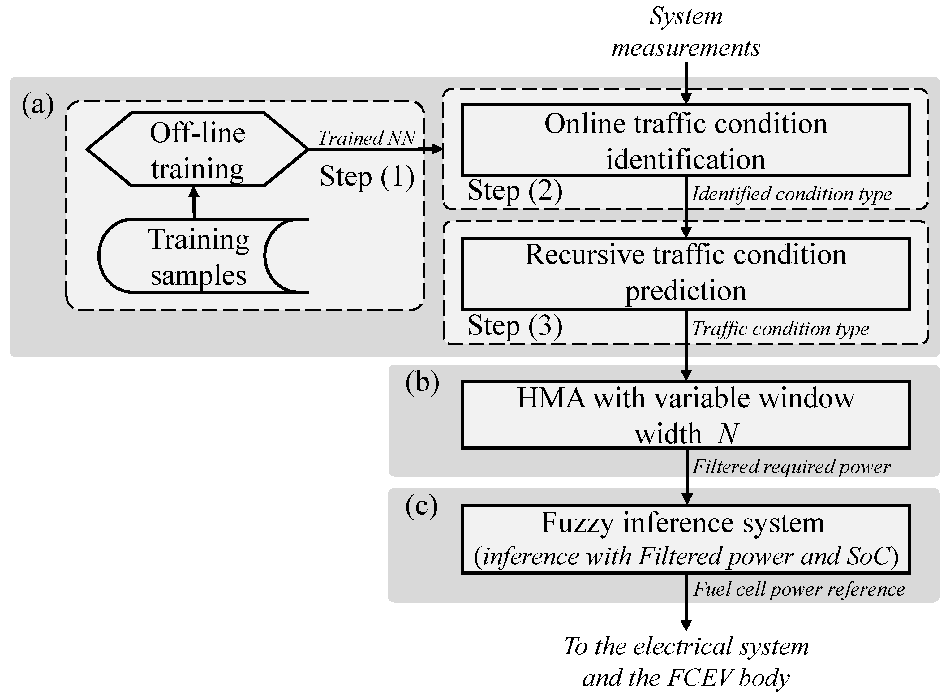
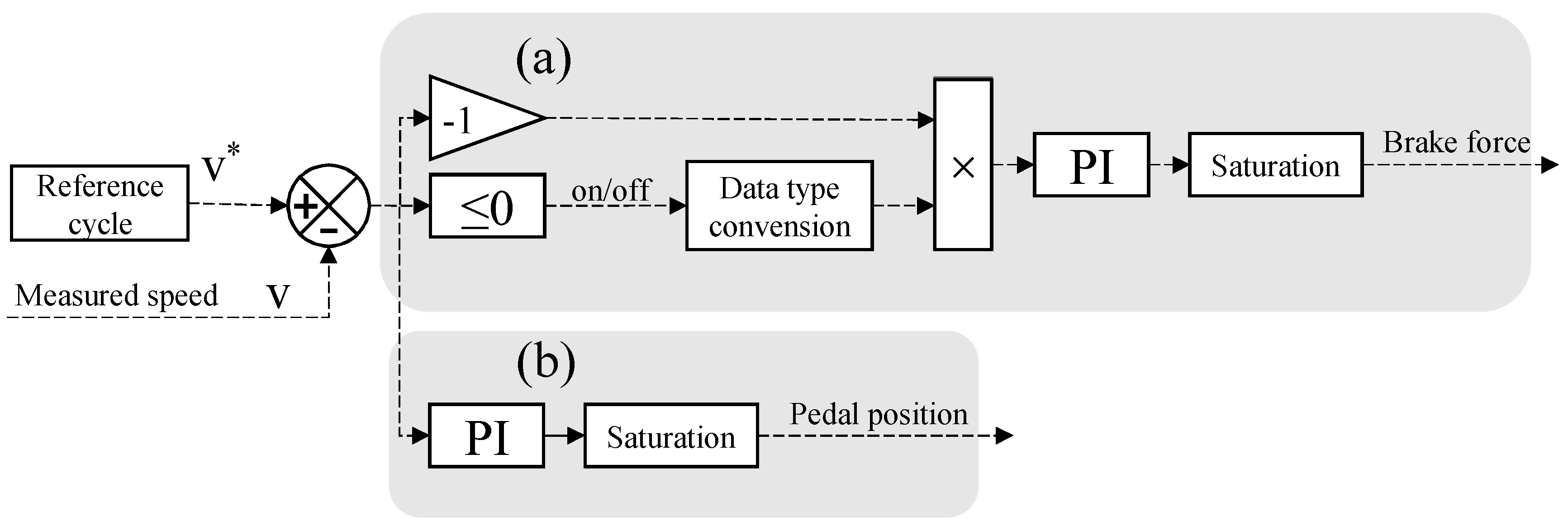
The flowchart of the proposed EMS is shown in Figure 2, which represents the working flow of the EMS block in Figure 1.
In Figure 2a, the block in the gray background is an ANN-based traffic-condition predictor that can forecast driving conditions according to real-time running signals of the FCEV and pass the prediction result on to the adjacent frequency-decoupling block labeled shown in Figure 2b, where an adopted HMA algorithm is shown; its window width is adjusted according to the predicted traffic condition among three predefined categories. The HMA filters out high-frequency components from the demanded power and transfers the low-frequency parts of the required power to the next block (Figure 2c in gray background). That block is based on fuzzy inference and is used to calculate output reference power of the fuel cell according to battery SoC and the low-frequency trend of the demanded power.

3.1. Traffic-Condition Categorizing

To make the proposed EMS adaptive to varying traffic conditions, driving-condition categories are defined in this section that were taken into account in the energy-management process.
According to Reference [
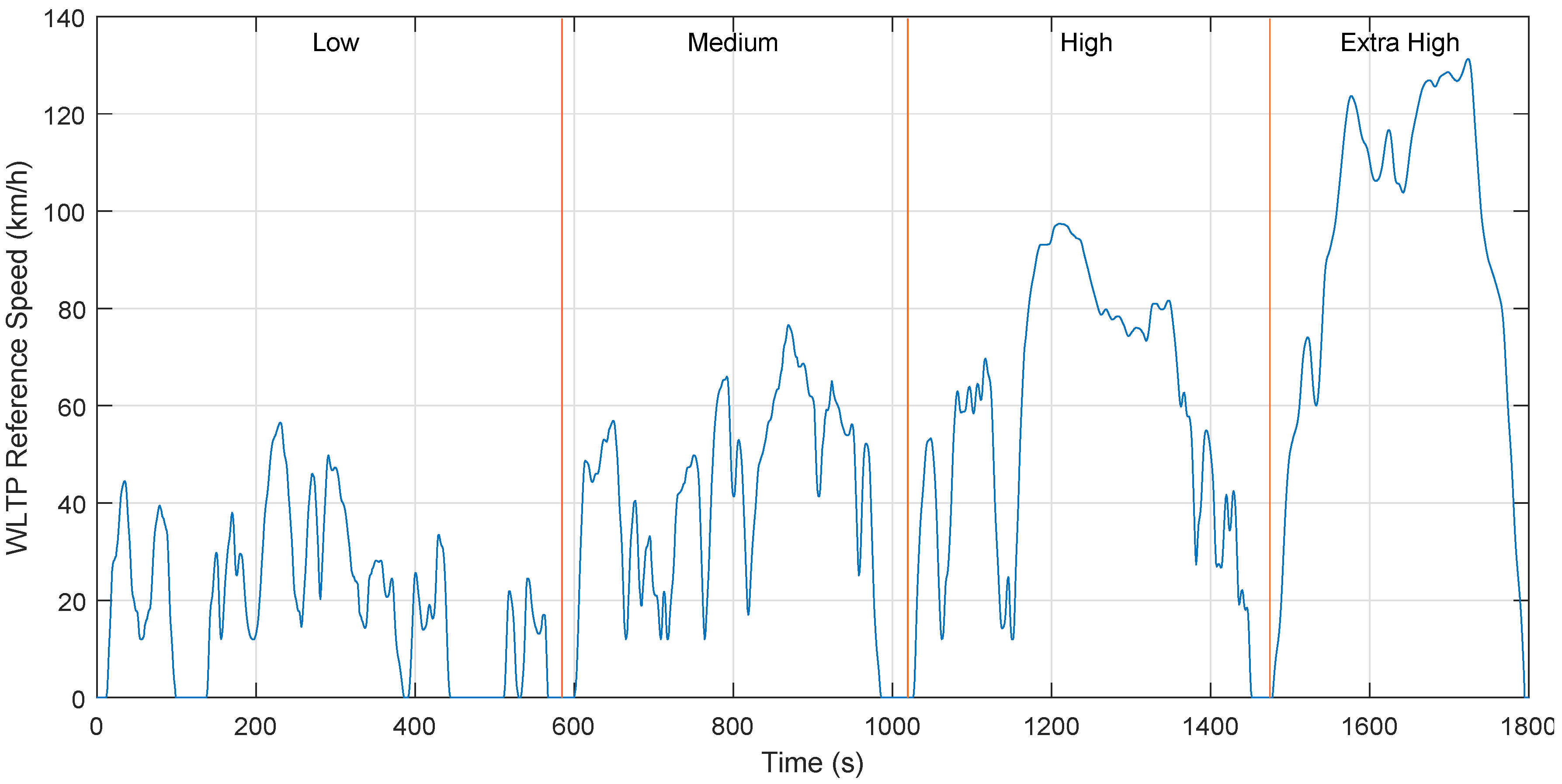
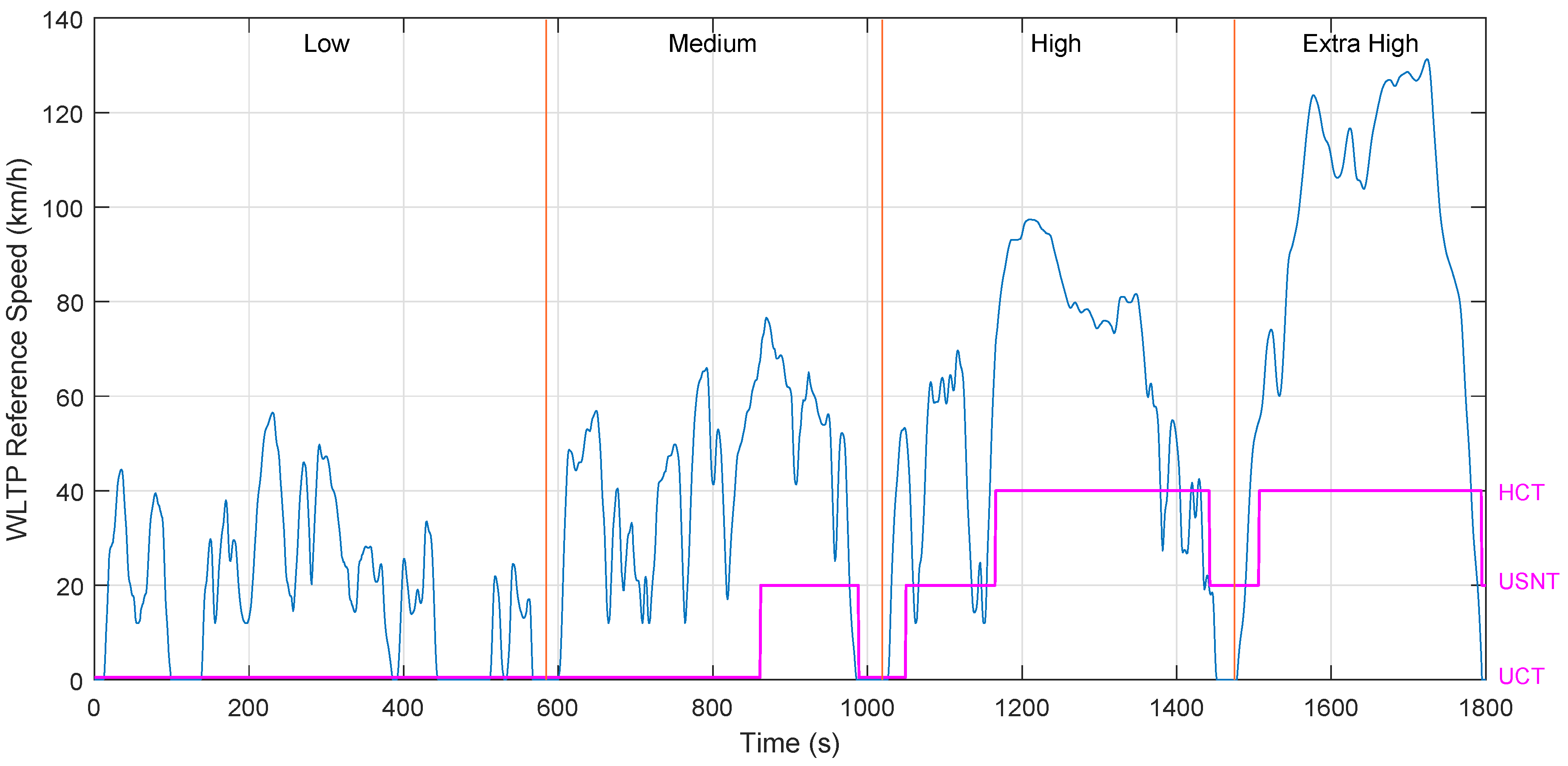
41], common traffic conditions can be divided into three main types—Urban Congestion Type (UCT), Urban/Suburb Normal Type (USNT) and Highway Clear Type (HCT). The UCT is the condition where a vehicle is driving on a congested urban road and its characteristics are low average speed with frequent idling. USNT includes situations where the vehicle is driving in urban or suburban areas with a better traffic environment; average speed is higher than that of UCT but due to the existence of traffic lights, idling frequency is still high. The HCT is the driving condition in a flat, closed and straight road with clear traffic, average speed is high and the vehicle is seldom idle. The characteristics of the three traffic conditions above are summarized in Table 1.

3.2. Neural-Network-Based Traffic-Condition Predictor

Because different traffic conditions lead to different power demands for driving an FCEV, a traffic-condition predictor was developed to enhance the adaptability of the EMS to different traffic conditions.
Although features of the defined traffic conditions in 
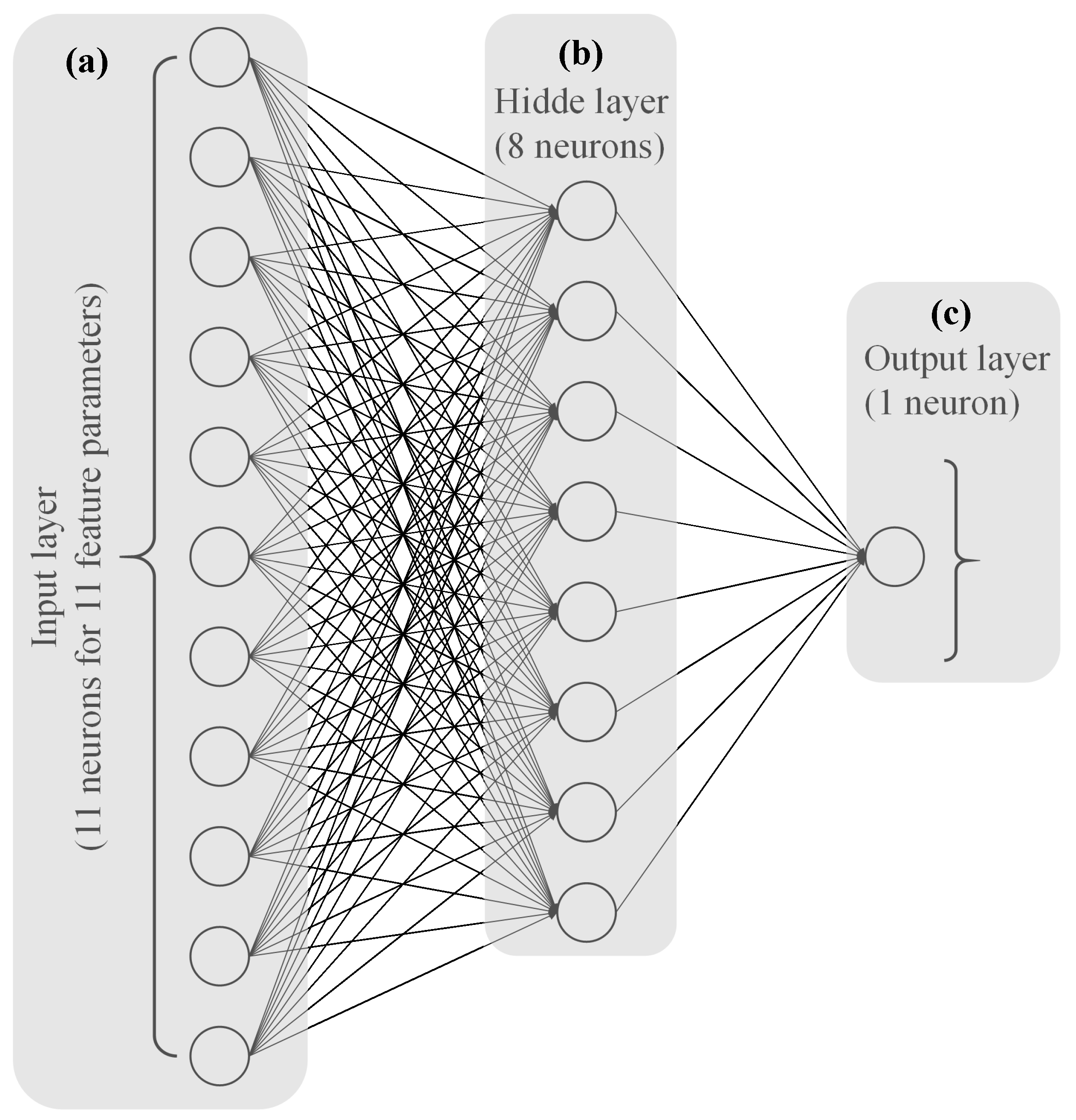
Table 1 are straightforward and in consistency with our experience, it is not easy to automatically identify current driving conditions in real time because characteristic parameters are coupled, and there are nonlinear relationships between driving parameters and condition types. Accordingly, a Back Propagation Neural Network (BPNN) was adopted to realize traffic-condition predictions due to its good nonlinear mapping capability. Then, the predicted result was used to adjust the window width of the subsequent HMA algorithm in the EMS working flow.
The structure of the BPNN is shown in Figure 3, which includes an input layer with 11 neurons, a hidden layer with eight neurons, and an output layer with one neuron. The network receives 11 selected feature parameters of the FCEV during the driving process and outputs the identified traffic-condition type from the three predefined categories (UCT, USNT, and HCT). The 11 selected driving-feature parameters are listed in Table 2.
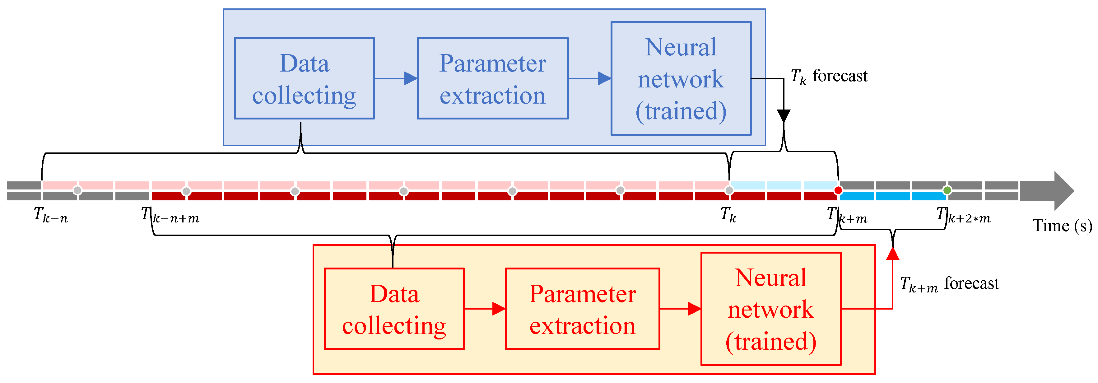
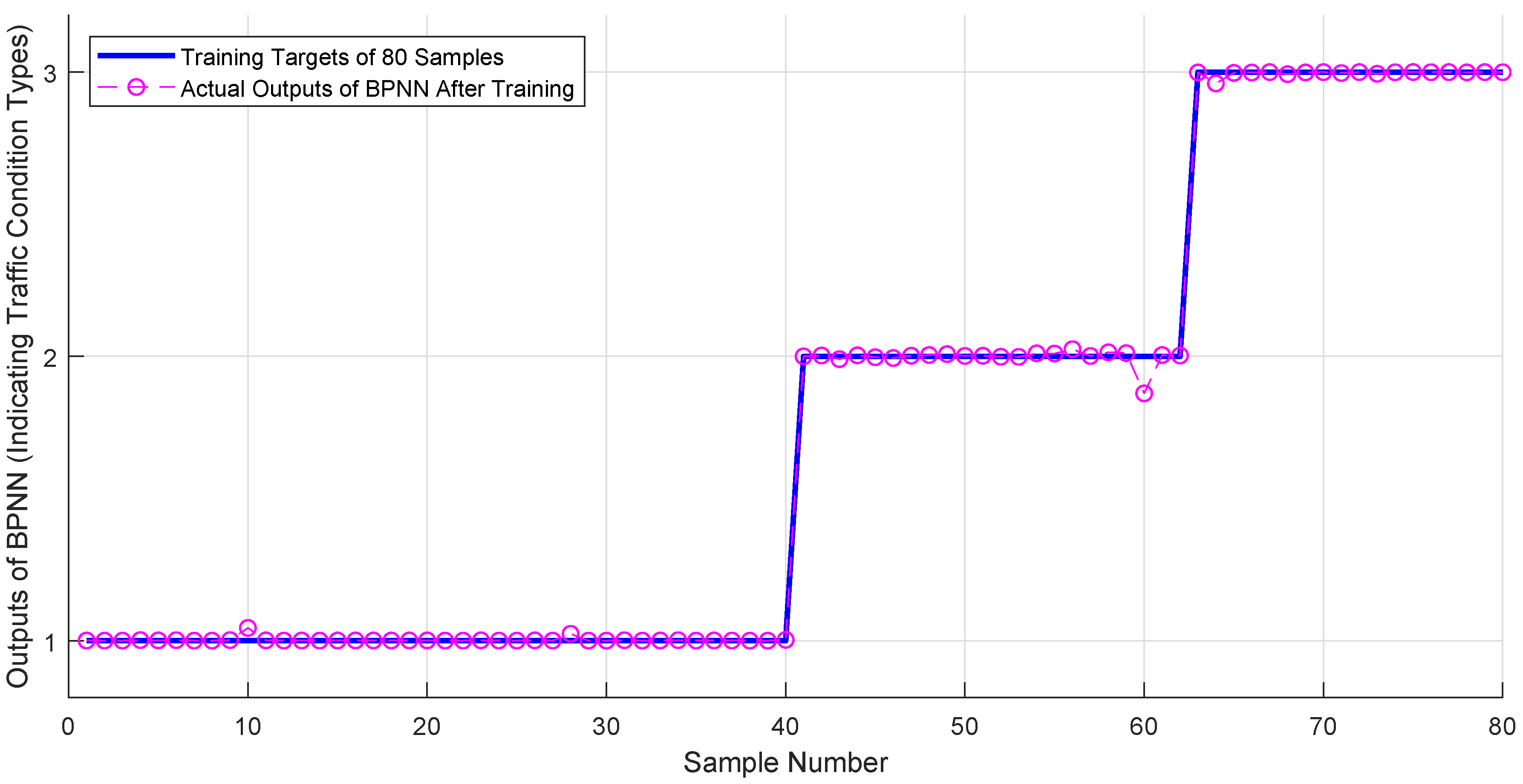
The working process of the BPNN-based traffic-condition-type prediction can be divided into three steps—(1) offline BPNN training; (2) online BPNN identification; and (3) recursive traffic-condition prediction.
In Step (1), the sample data of different road conditions are collected and used to train the BPNN offline with a back-propagation algorithm. After being trained, the BPNN becomes an approximation with high precision between selected driving parameters and traffic condition types. Then, in Step (2), the trained BPNN is used to identify the traffic condition online. In reality, traffic conditions normally gradually transition from one to another (although they may be frequent and fast); online identification is done every m (m is an integer and greater than 1) sampling periods instead of at each sampling instant. During identification, BPNN inputs are the 11 feature parameters calculated from the latest n (n is an integer and greater than 1) sampling data, and output is the recognition of the current driving-condition type. Finally, the identified traffic-condition type is used as the prediction result for the coming m sampling period. A new online identification is repeated after m sampling periods at the m + n sampling instant. This recurrent prediction process is illustrated in Figure 4.

3.3. Hull-Moving-Average-Based Frequency Decoupling

During a real driving procedure, instantaneous high power is often required to rapidly speed up an FCEV. As discussed before, the output power characteristic of a fuel cell makes it difficult to meet this prompt high-power demand. To solve this problem, a frequency-decoupling method that can separate low-frequency components from demanded power by filtering high-frequency components is essential for the efficient operations of a hybrid-source-powered FCEV [42,43,44]. The low-frequency components of the demanded power are fulfilled by the fuel cell, while high-frequency power requirements are satisfied by the battery.
A Moving Average (MA) algorithm can filter out high-frequency components and retain the low-frequency trend of a signal, and this makes the MA applicable to smooth the demanded power of an FCEV [45]. Common MA algorithms include Simple MA (SMA), Weighted MA (WMA), Exponential MA (EMA) and Hull MA (HWA).
The SMA, essentially a low-pass filter, calculates the mean value of the data within a filter window (with a window width of N) and takes this average as a filtered value. The SMA assigns the same weight to all data in the window and results in an obvious filtering lag. Larger filter window width N leads to a smoother filtering output but increases filtering lag, which reduces frequency-decoupling performance [45]. To address this filtering-lag problem, WMA and EMA algorithms were developed by assigning bigger weights to more recent data, and smaller weights to far-off data in the window with linear and exponential calculations, respectively [46]. For example, the calculation equation of the WMA is as follows:
p k ^ ( N ) = N p k + ( N 1 ) p k 1 + + p k N + 1 ( N + 1 ) N / 2
where p k is the value of a time sequence at time k, and p k ^ ( N ) is the average value of p k after a WMA calculation with a window width of N.
It can be seen from Equation (1) that most recent data p k are multiplied by the biggest weight of N, while earliest value p k N + 1 is multiplied by the smallest weight of 1. This mechanism improves the trend-tracking capability of the filter and decreases lag but the disadvantages of the WMA and EMA are that assigned weights and window width are normally constants for the whole time series.
The HMA algorithm can improve the above insufficiency by carrying out calculations shown in Equation (1) threefold with different filter-window widths; smoother filtering results can be obtained with decreased filtering lag. Accordingly, the HMA algorithm was adopted in this paper for the demanded power-frequency decoupling, and its calculation procedure has the four following steps [47].
Step 1: HMA calculates a WMA with Equation (1) with a period of N 1 = r o u n d ( N / 2 ) .
p k ^ ( N 1 ) = N 1 p k + + p k N 1 + 1 ( N 1 + 1 ) N 1 / 2
Step 2: The HMA calculates a WMA with a period of N.
p k ^ ( N ) = N p k + + p k N + 1 ( N + 1 ) N / 2
Step 3: A new data series is generated with the results of Steps 1 and 2.
p k = 2 p k ^ ( N 1 ) p k ^ ( N )
Step 4: HMA calculates a WMA with a period of N 2 = s q r t ( N ) on the new data series.
p k ^ ( N 2 ) = N 2 p k + + p k N 2 + 1 ( N 2 + 1 ) N 2 / 2
In the HMA algorithm, filter-window width N is a significant parameter determining the filtering effect. The value of N is connected with the signal characteristics and a well-selected value can result in smoother filtering output with reduced filtering lag. For example, the demanded power to drive an FCEV in the HCT has fewer fluctuations and large amplitude. To process this signal with HMA, a smaller value of N can be chosen to compromise between signal smoothing and filtering lag. For the demanded driving power in UCT, on the other hand, power has more variations with relatively small amplitudes; in this case, a bigger value of N can be selected to smooth the filtering result. In the case of driving in a USNT, a power signal with medium fluctuations and moderate amplitudes should be filtered with a value of N between the two situations above. Therefore, an N value and traffic-condition type are closely connected with the required driving power of this traffic-condition type; if a value of N is well-selected for a particular traffic-condition type, a better power-filtering result can be obtained. On the basis of this observation and the summary of comparison simulation results during our research process, the selected N values in different traffic-condition types are listed in Table 3.
According to Table 3, in each-frequency decoupling process, HMA filter-window width N is adjusted by the traffic condition forecasted by the BPNN to improve the filtering effect and the adaptability of the EMS to various driving conditions.

3.4. Fuzzy-Inference-System-Based Fuel-Cell Energy Management

The HMA-based frequency-decoupling method retains the low-frequency components of the demanded power for the fuel cell to match its load characteristic, and leaves high-frequency power to the battery. Although the traffic-condition-adapted window-width adjustment is adopted in the HMA, it still has to manage the hybrid-power sources. This algorithm only considers the output-power characteristics of the two power sources in the frequency domain and does not take battery SoC maintenance into account.
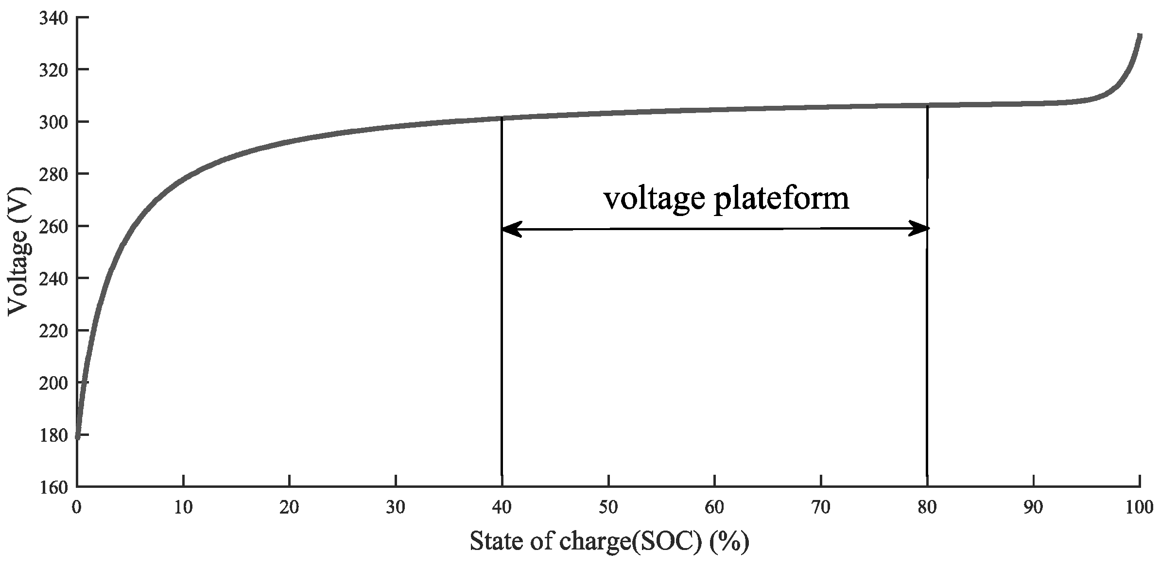
The SoC is an essential parameter of a battery, and it is normally used as an indicator of the amount of remaining energy as compared with its fully charged amount in percentage. Consider that the battery should always be well-protected to avoid overcharging or overdischarging, the SoC should be maintained within an allowed range to prevent possible damage. Another consideration is that, in the hybrid-power supply of the FCEV shown in Figure 1, the battery is directly connected to the DC bus without any converter. In this case, the battery needs to keep the output voltage as stable as possible to support the DC bus voltage with variable SoC. According to the voltage/SoC characteristic of a battery, if the battery’s voltage platform needs to be maintained, the SoC should be kept in a particular range. An example of the voltage platform with a battery of 288 V and 14 Ah is shown in Figure 5 [48]. From this figure, it can be seen that SoC maintenance range is 40%–80% to maintain the voltage platform; if the SoC goes beyond this range, output voltage apparently increases or decreases. Accordingly, for battery protection and DC bus voltage support, the battery SoC is considered be bounded within the above range by the EMS proposed in this paper.
An FIS was shown to be efficient in the energy-management applications for its intelligence and model free advantages [49]. Therefore, an FIS was adopted as the last stage of the proposed EMS. As can be seen in Figure 2, during the working flow of the proposed EMS, the filtering result of the demanded power, which corresponds to its low-frequency components, by the HMA is given to a fuzzy system for inference; the second input of the FIS is the estimated SoC of the battery. After the fuzzification, fuzzy-implication-calculation and defuzzification processes, a power reference is generated by the FIS for the fuel cell and its DC/DC converter to control its output power. Meanwhile, inadequate power with high-frequency dynamics is calculated and supplied by the battery to keep the power balanced.
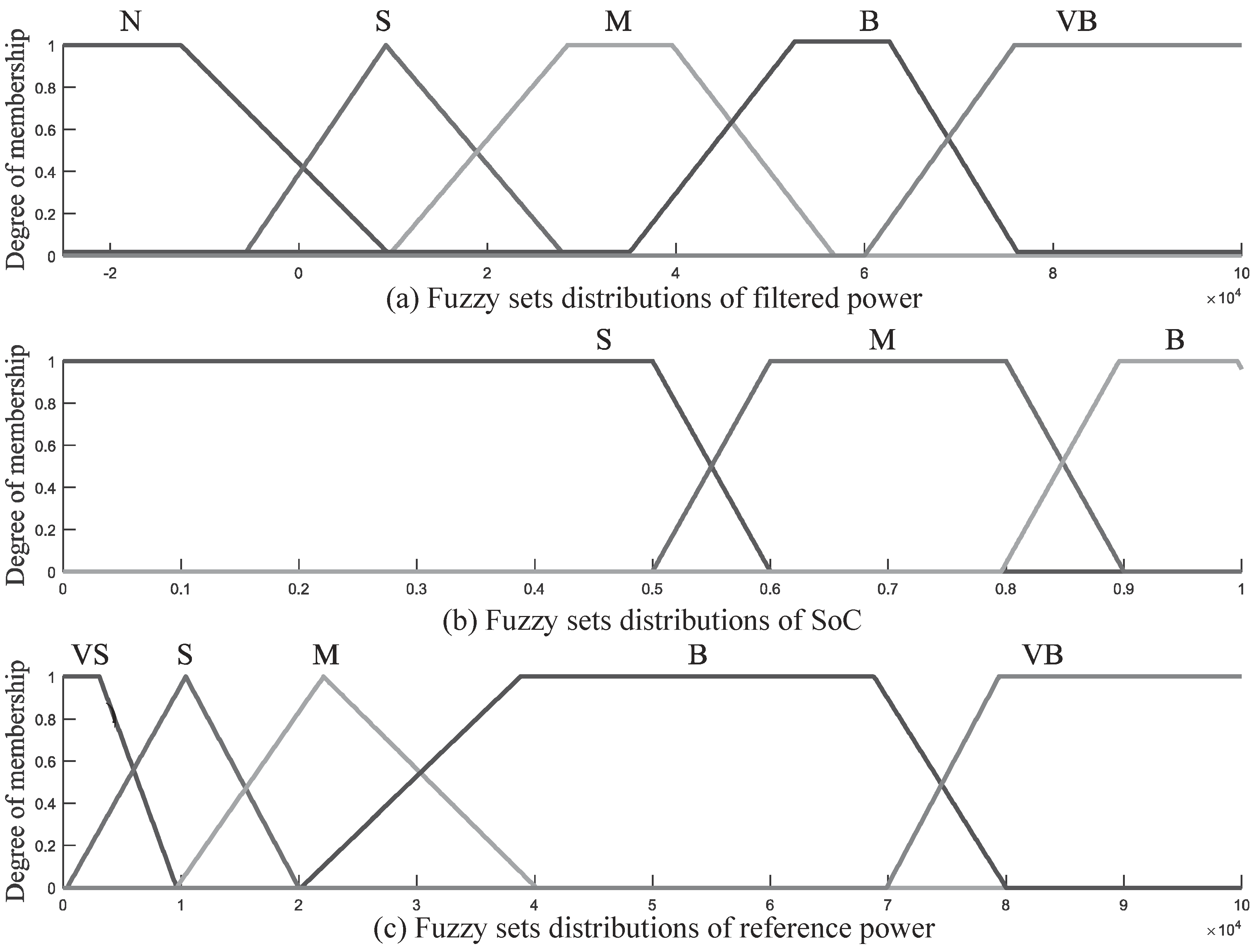
To realize fuzzification, the first input of the FIS, noted as P d * , which stands for the low-frequency components of the demanded power, is divided into five fuzzy sets; the second input, noted as SoC, which represents the state of charge of the battery, is divided into three fuzzy sets. The output of the FIS, noted as P f c s , which denotes the reference power of the fuel cell, is also divided into five fuzzy sets. The selected membership functions and the fuzzy-set distributions are shown in Figure 6.
With these fuzzy sets, 15 fuzzy inference rules in the IF-THEN form were designed as follows.
  • IF P d * is N and SoC is S, THEN P f c s is VS;
  • IF P d * is N and SoC is M, THEN P f c s is VS;
  • IF P d * is N and SoC is B, THEN P f c s is VS;
  • IF P d * is S and SoC is S, THEN P f c s is M;
  • IF P d * is S and SoC is M, THEN P f c s is S;
  • IF P d * is S and SoC is B, THEN P f c s is VS;
  • IF P d * is M and SoC is S, THEN P f c s is B;
  • IF P d * is M and SoC is M, THEN P f c s is M;
  • IF P d * is M and SoC is B, THEN P f c s is S;
  • IF P d * is B and SoC is S, THEN P f c s is B;
  • IF P d * is B and SoC is M, THEN P f c s is B;
  • IF P d * is B and SoC is B, THEN P f c s is M;
  • IF P d * is VB and SoC is S, THEN P f c s is VB;
  • IF P d * is VB and SoC is M, THEN P f c s is VB;
  • IF P d * is VB and SoC is B, THEN P f c s is M;
Mamdani inference was adopted to realize the implication calculation, and a centroid defuzzification method was applied to convert the inference result from a fuzzy value to an accurate one. Centroid defuzzification is expressed with the following equation [50].
u = x μ A ( x ) d x μ A ( x ) d x
where x is a linguistic variable, μ A ( x ) is the membership value of x in a fuzzy set A, and u is the crisp value after the defuzzification.

4. Simulation and Result Analysis

4.1. Simulation Platform and Parameter Configurations

In order to evaluate the performance of the proposed traffic-condition-prediction-based HMA-FIS EMS, a simulation platform was built with the MATLAB/Simulink and Simscape Driveline, SimPowerSystems, and Powertrain Blockset toolboxes. This platform realized the FCEV structure shown in Figure 1, and was built by modifying a simulation example, Fuel Cell Vehicle Power Train (FCVPT) (Available for download with https://ww2.mathworks.cn/matlabcentral/fileexchange/33309-fuel-cell-vehicle-fcv-power-train). The simulation platform is shown in Figure 7.
The Class 3b test cycle of the Worldwide harmonized Light vehicle Test Procedures (WLTPs) was adopted in the simulations as a speed profile; it is a 1800 s and 23.266 km test cycle with a top vehicle speed of 131.3 km/h. This test cycle includes a low-speed section, a medium-speed section, a high-speed section, and an ultrahigh-speed section. The velocity and section distributions over 1800 s are shown in Figure 8. Statistical data of this test cycle are summarized in Table 4.
In the ’Energy Management System’ block of Figure 7, the EMS presented in Section 3 is realized. In the ’FCEV Electrical System’ block, a Proton Exchange Membrane Fuel Cell (PEMFC) rated at 288 V and 100 kW was adopted as the main power source of the FCEV. A DC/DC converter in current-regulated mode was used to connect the PEMFC to the DC bus. A 288 V and 13.9 Ah lithium-ion battery was equipped as an auxiliary power source, which is directly connected to the DC bus. The battery SoC is estimated by a classical current-integration method. The electrical motor is a 288 V, 100 kW, and 8-pole salient rotor PMSM with the associated drive based on AC6 blocks of the SimPowerSystems toolbox. A flux-weakening vector control is used to achieve a maximum motor speed of 12,500 rpm. During simulations, the output power of the fuel cell was limited between 2 and 100 kW, and the initial value of the battery SoC was set to be 40.3%. A more detailed model description and parameter configurations can be found in [34]. In the ’FCEV Dynamics’ block of Figure 7, a 1625 kg light vehicle with a gearbox was realized, and the parameters of the EV are shown in Table 5.
To be more practical in the simulations, a Mechanical Brake Assist System (MBAS) was designed and added to the EV model to make the FCEV follow the reference speed when there is sudden braking. The MBAS and the pedal-position control schematic diagram are shown in Figure 9. The MBAS is activated when the measured vehicle speed is greater than the reference value; the brake force is first calculated through a PI controller and a limitation, and then applied onto a pair of double shoe breakers on the wheels to reduce vehicle speed. Similar to mechanical brake control, vehicle-speed control is also based on a PI controller and the control output is the pedal position within a preset range whose value represents accelerating/decelerating demands.

4.2. Simulation-Result Comparison and Analysis

Simulations were carried out on the FCEV simulator shown in Figure 7 with the proposed EMS and speed reference shown in Figure 8. To validate the performance of the proposed EMS, the adopted WLTP speed reference was also applied to the FCVPT example with its original EMS, which is based on predefined rules to maintain battery SoC; the results of these two simulations were compared.

4.2.1. BPNN Training and Traffic-Condition-Prediction Results

According to the working flow of the BPNN-based traffic-condition predictor shown in Figure 2, 80 samples were extracted from the test cycle to train the neural network offline. From these samples, 40 belonged to the UCT, 22 belonged to the USNT and 18 belonged to the HCT; each sample included 11 feature parameters as its inputs and one target output indicating the traffic-condition type of this sample. After training the BPNN with Levenberg–Marquardt backpropagation by applying the MATLAB ’trainlm’ function, the target and actual outputs of the BPNN of these 80 samples are shown in Figure 10. The maximum and minimum output errors were 0.1301 and −0.0448, respectively, after training and mean square error was 0.0004.
Applying the trained BPNN in the simulation and the traffic-condition-type prediction, results were obtained and are shown in Figure 11.

4.2.2. FCEV Speed-Control-Simulation Results and Comparison

Vehicle reference speed, measured speed and their errors from the two simulations are shown in Figure 12 and Figure 13. It can be seen from the two figures that the measured speed overlays the reference speed, which indicates that the FCEV followed the WLTP reference speed very well in both simulations. During the 1800 s test cycle, the FCEV speed-control error with the proposed EMS was between −1.59 and 2.85 km/h with an average value of −0.0019 km/h, while error with the example EMS was between −4.54 and 2.19 km/h with an average of −0.0046 km/h, which is bigger than the mean value of the proposed method. These simulation results demonstrated that the proposed EMS could control the FCEV velocity well by managing the hybrid-power sources.

4.2.3. Electrical-Power Simulation Results and Comparison

The electrical power of the motor, the output power of the fuel cell and the output power of the battery from two simulations are shown in Figure 14, Figure 15 and Figure 16 respectively. Mean, minimum and maximum values of these power measurements are summarized in Table 6.
As can be seen from Figure 14 and Table 6, the demanded power of the motor frequently varies to drive the FCEV to follow the WLTP reference speed; the higher the speed that is referred, the bigger the power that is required. Statistically, the maximum required power was 62.83 kW in both simulations and average power was 11.66 kW with the proposed EMS and 11.26 kW with the example EMS—very close values.
From Figure 15 it can be seen that, during the first 600 s of the simulations when the referred FCEV speed was low, fuel-cell output power by the proposed EMS was higher than the power by the example EMS; during the last 600 s of the simulations, when reference speed was very high, the fuel cell delivered less power through the proposed EMS than power through the example EMS. These observations can also be seen from Table 6, the maximum power of the fuel cell was 52.26 kW by the proposed EMS and 60.24 kW by the example EMS, which indicates that more power was undertaken by the battery during peak power-demand periods with the management of the proposed EMS; in the mean time, average fuel-cell power by the proposed EMS was 13.54 kW, higher than the value of the example EMS (11.92 kW), which indicated that the principal power-supply role of the fuel cell was strengthened by the proposed EMS and that the fuel cell delivered most power required by the motor.
From Figure 16 it can be seen that, during the first 600 s of the simulations when there were many instances of braking in the test cycles, the battery recovered more energy with the proposed EMS than with the example EMS; in the last 600 s of the simulations, when the reference speed was very high, the battery delivered higher power to support acceleration in high speed. These observations can also be verified by Table 6, the maximum output power of the battery by the proposed EMS was 13.26 kW, higher than the value of 7.23 kW by the example EMS, which indicated that the battery could support more power in response to very high power demands. The absolute value of the minimum battery power by the proposed EMS was 25.29 kW, which was also higher than that by the example EMS (13.75 kW), which shows that the battery could absorb more braking energy through the proposed EMS. By comparing Figure 15 and Figure 16 it can also be found that the battery-power fluctuations were more frequent than those of the fuel cell, which showed that the battery takes on higher-frequency components of demanded power than the fuel cell does.

4.2.4. Hydrogen-Consumption Simulation Results and Analysis

Fuel-cell hydrogen consumption in two simulations is shown in Figure 17.
From Figure 17, it can be seen that the hydrogen consumption of the fuel cell was proportional to its output power, shown in Figure 15 for the two simulations. In the low-speed section of the test cycle, because the fuel cell delivered more power through the proposed EMS than through the example EMS, hydrogen consumption by the proposed EMS was also higher; during the last 600 s of the simulations, hydrogen consumption of the proposed EMS was lower in accordance with the smaller power output of the fuel cell. During the entire simulations, average hydrogen consumption was 0.9113 L/s (by the proposed EMS) and 0.7946 L/s (by the example EMS). The higher mean value also indicated that the proposed EMS could manage the fuel cell to undertake and deliver more power during the simulations.

4.2.5. Battery SoC Maintenance Simulation Results and Analysis

Variations of battery SoC in the two simulations are shown in Figure 18.
As mentioned in the previous section, the initial value of the battery SoC was 40.3% in the simulations. It can be seen from Figure 18 that the SoC varied from 40.3% to 66.30% in the proposed EMS and from 40.32% to 49.56% in the example EMS. Although SoC fluctuations in the two simulations were both within the expected range of 40%–80%, with the same test-cycle reference, the proposed EMS allowed battery charge and discharge in a wider SoC range, which means that battery capacity could be better utilized to meet high power-density requirements during rapid acceleration or deceleration operations. A potential problem related to this result is that a wider SoC variation range may negatively impact the charging and discharging cycles of a battery, and this may lead to a choice-making problem in practice on the better dynamic characteristics or a longer battery lifetime.
From the above simulation-result comparison and analysis, it can be seen that the proposed EMS could manage hybrid-power sources and allow the FCEV to track reference speed with negligible control errors. The EMS can adapt to different traffic conditions contained in the WLTP test cycle and have better utilization of the fuel cell and the battery in compliance with their output-power characteristics.

5. Conclusions and Future Studies

This paper proposed a novel energy-management method combining the neural-network technique, the hull moving-average algorithm and the fuzzy-inference system to realize traffic-condition-based energy management for an FCEV powered by a fuel cell and a battery.
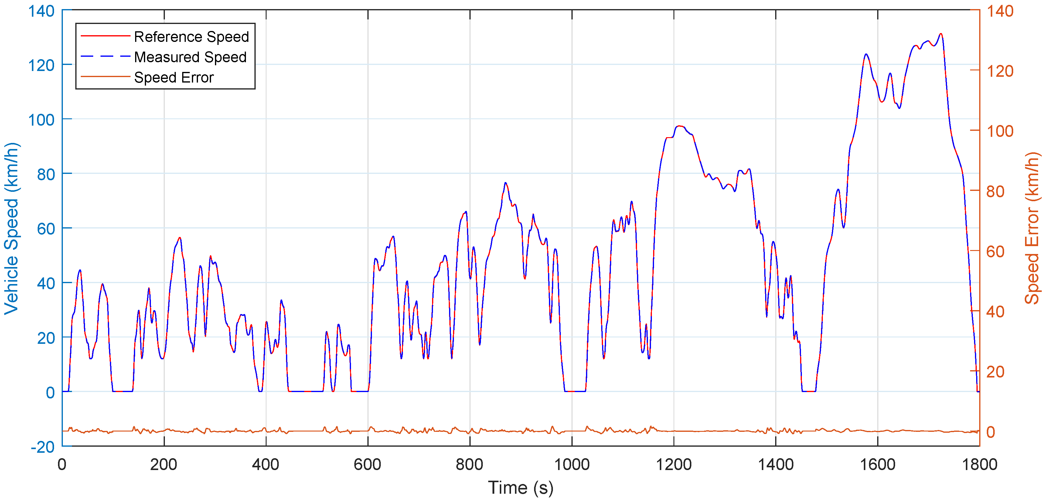
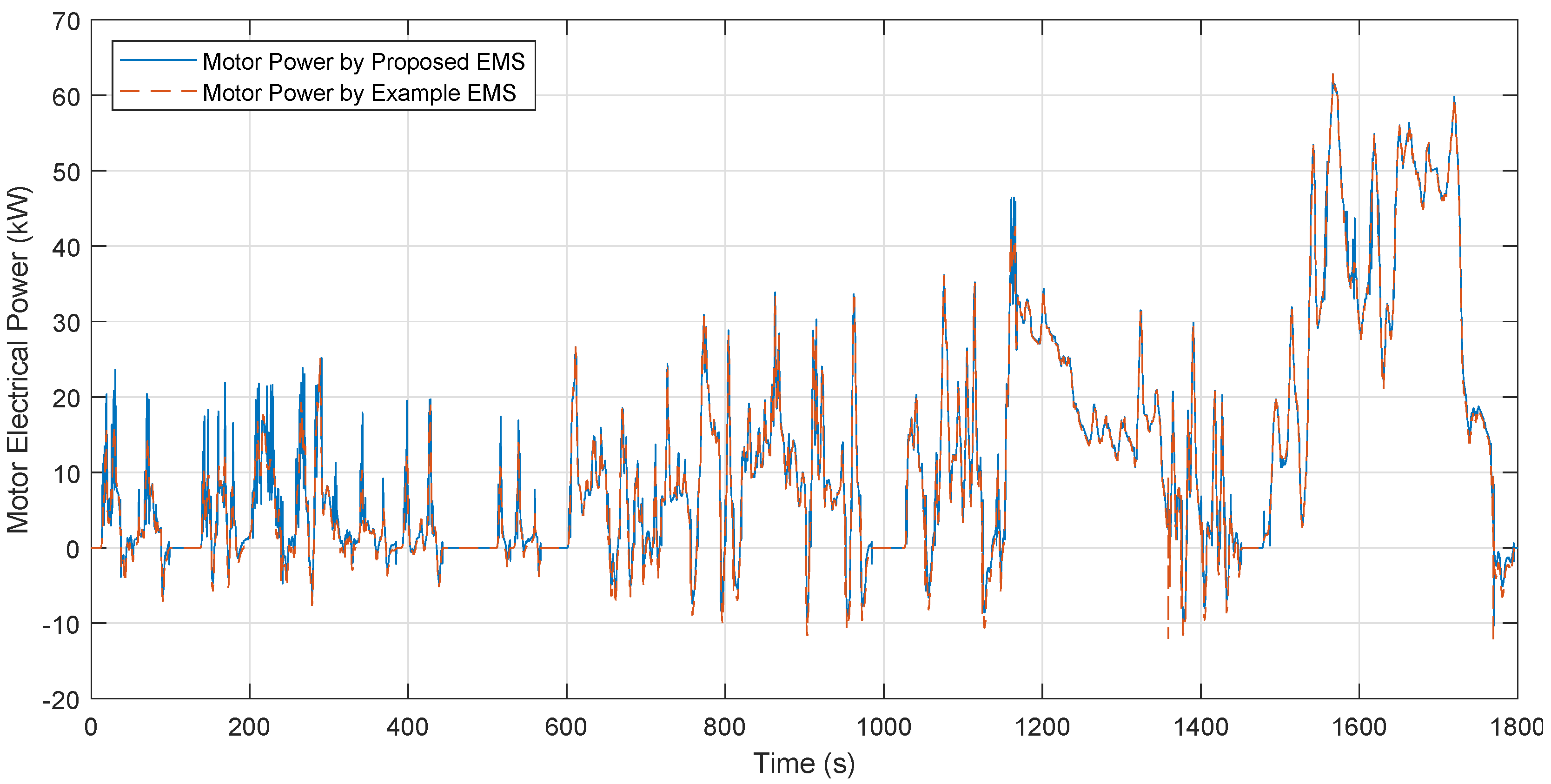
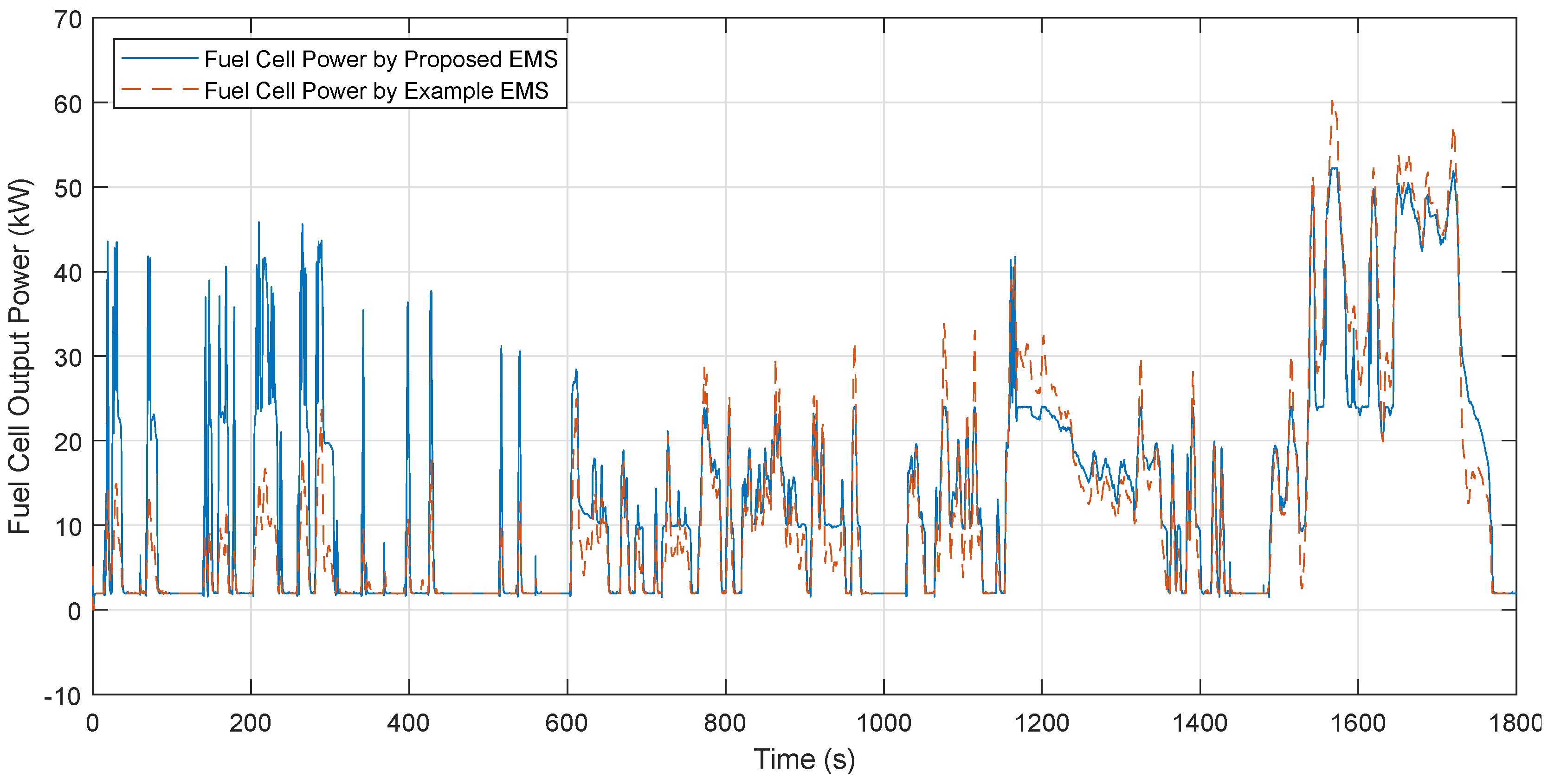
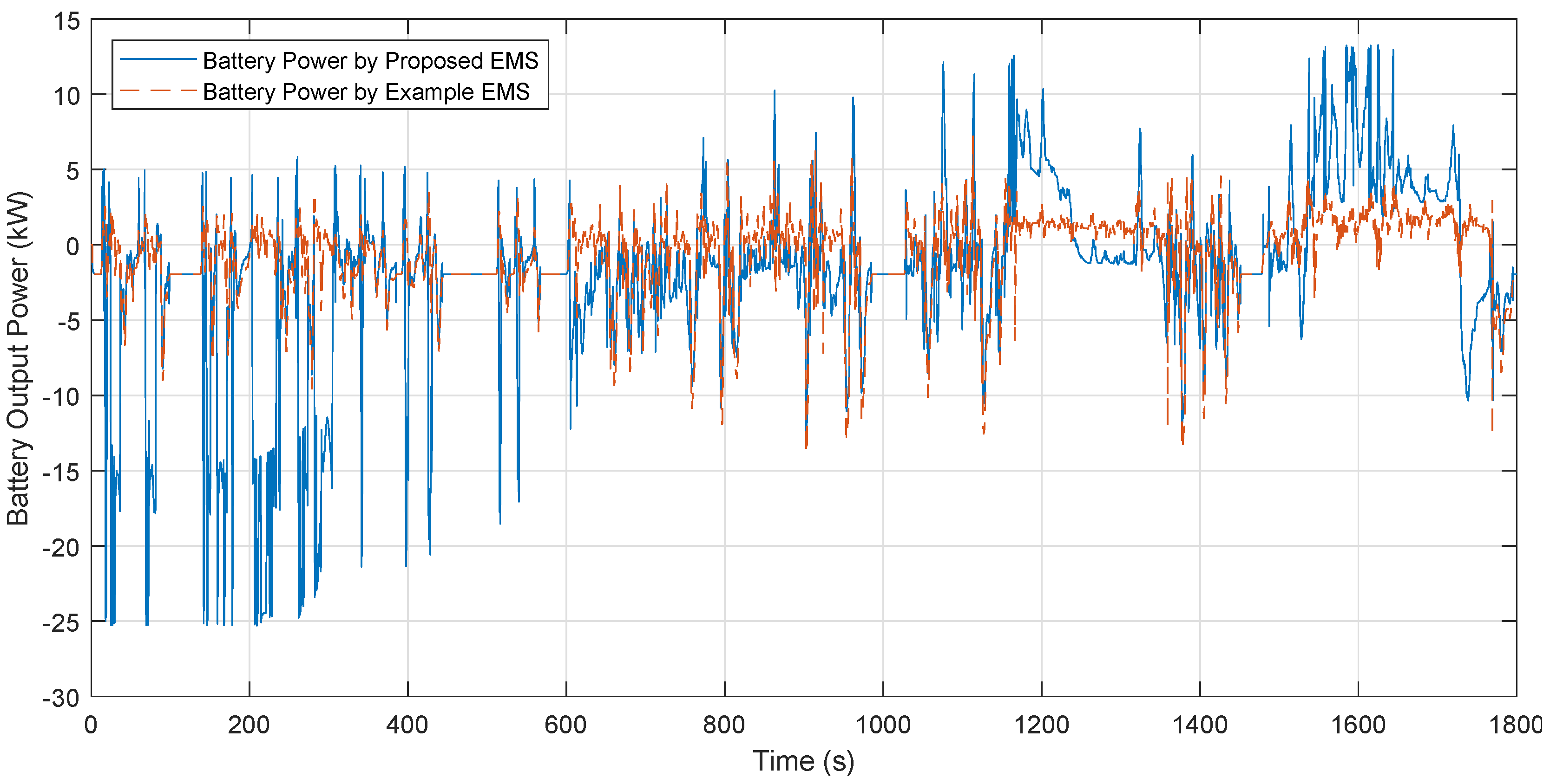
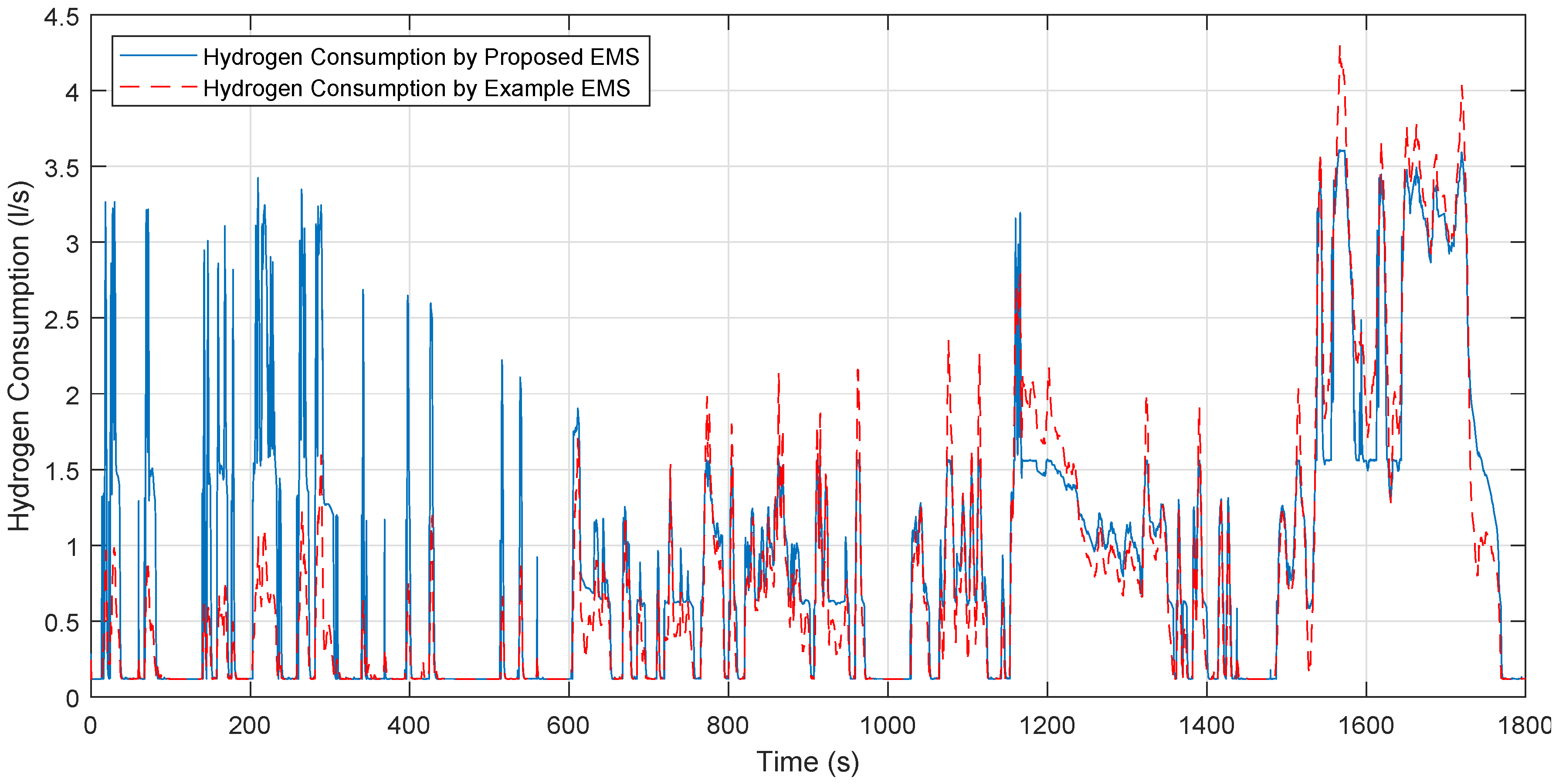
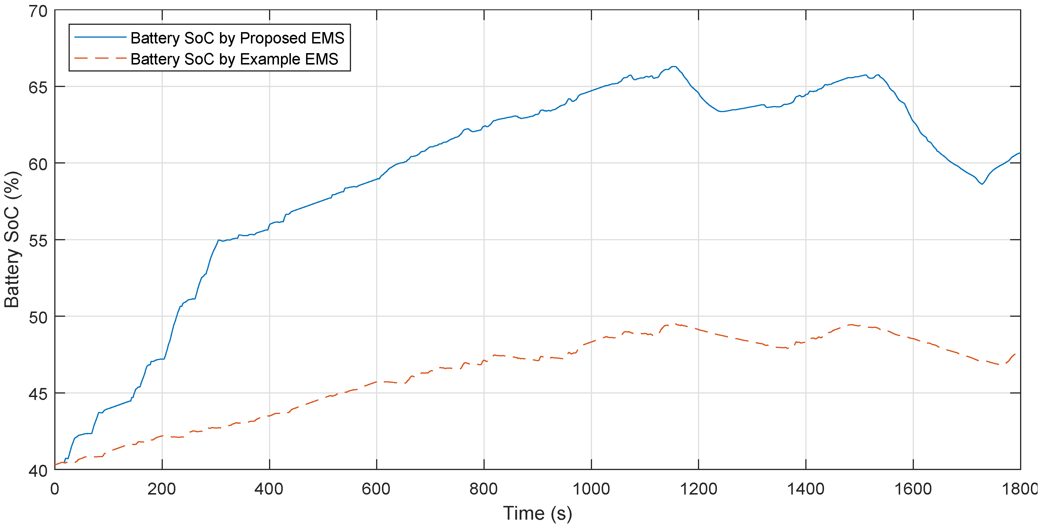
In this method, a BPNN was designed to identify and predict the traffic-condition type and the predicted result was used to adjust the width of the HMA filter window; with this parameter-adaptive mechanism, the HMA filtering effect could be improved to adapt to different power demands in various driving conditions. The filtering result keeps the low-frequency parts of the demanded power with consideration of the traffic situation and is then forwarded to an FIS. The FIS employs the fuzzified values of the filtered power and the estimated battery SoC for fuzzy-implication calculations and obtains the reference power of the fuel cell. The rest of the demanded power with high-frequency parts is undertaken by the battery; meanwhile, the SoC of the battery can be maintained within a particular range for battery protection. Finally, a simulation platform was built on the basis of the FCVPT example. The same WLTP test cycle was applied to this simulation platform with the proposed EMS and to the example with its own EMS for comparison simulations. Simulation results were analyzed to verify the effectiveness of the proposed EMS.
The proposed EMS has the advantages of simple calculation and good adaptability, which can deal with deficiencies of existing frequency-decoupling- or fuzzy-logic-based energy-management methods. However, there are still problems open for further research and discussion, such as computational-complexity analysis of the proposed method to validate its availability for practical real-time applications; and battery lifetime should be given more consideration in the proposed EMS to compromise for charging/discharging cycles with the wider SoC variation range. These problems will be important research targets for further studies.

Author Contributions

Conceptualization, G.Y.; methodology, Q.G. and H.J.; software, C.D.; validation, Y.W.; formal analysis, M.A.-A.; supervision, L.M.

Funding

This research was funded by the Zhejiang Provincial Natural Science Foundation of China with Grant No. LR17F030005, the Shanghai Science and Technology Committee Foundation with Grant No. 19040501700, and the National Natural Science Foundation of China with Grant No. 61603246.

Conflicts of Interest

The authors declare no conflict of interest.

References

  1. Leuchter, J.; Quang, H.D.; Popela, M. Development of mobile electrical vehicle for EMI applications. J. Eng. 2019, 2019, 3660–3664. [Google Scholar] [CrossRef]
  2. International Energy Agency (IEA). Global EV Outlook 2019—Scaling-up the Transition to Electric Mobility; Report; IEA: Paris, France, 2019. [Google Scholar]
  3. Silva, F.A. Modern Electric, Hybrid Electric, and Fuel Cell Vehicles, Third Edition [Book News]. IEEE Ind. Electron. Mag. 2018, 12, 46–48. [Google Scholar] [CrossRef]
  4. Lomonova, E.A.; Paulides, J.J.H.; Wilkins, S.; Tegenbosch, J. ADEPT ’ADvanced electric powertrain technology’ Virtual and hardware platforms. In Proceedings of the 2015 Tenth International Conference on Ecological Vehicles and Renewable Energies (EVER), Monte-Carlo, Monaco, 31 March–2 April 2015; pp. 1–10. [Google Scholar] [CrossRef]
  5. International Energy Agency (IEA). The Future of Hydrogen; Report Prepared by the IEA for the G20, Japan; IEA: Paris, France, 2019. [Google Scholar]
  6. Hu, X.; Zou, C.; Tang, X.; Liu, T.; Hu, L. Cost-optimal energy management of hybrid electric vehicles using fuel cell/battery health-aware predictive control. IEEE Trans. Power Electron. 2019. [Google Scholar] [CrossRef]
  7. Saib, S.; Hamouda, Z.; Marouani, K. Energy management in a fuel cell hybrid electric vehicle using a fuzzy logic approach. In Proceedings of the 2017 5th International Conference on Electrical Engineering-Boumerdes (ICEE-B), Boumerdes, Algeria, 29–31 October 2017; pp. 1–4. [Google Scholar] [CrossRef]
  8. Marzougui, H.; Kadri, A.; Amari, M.; Bacha, F. Improvement of energy management algorithm for fuel cell electrical vehicle with fuzzy logic. In Proceedings of the 2017 18th International Conference on Sciences and Techniques of Automatic Control and Computer Engineering (STA), Monastir, Tunisia, 21–23 December 2017; pp. 212–217. [Google Scholar] [CrossRef]
  9. Pany, P.; Singh, R.K.; Tripathi, R.K. Power management of fuel cell and battery fed DC motor drive for electric vehicle application. In Proceedings of the IEEE-International Conference on Advances in Engineering, Science And Management (ICAESM-2012), Nagapattinam, Tamil Nadu, India, 30–31 March 2012; pp. 363–368. [Google Scholar]
  10. 2019 Toyota Mirai Fuel Cell Electric Vehicle Full Specification. Available online: https://ssl.toyota.com/mirai/fullspecs.html (accessed on 4 October 2019).
  11. Qi, X.; Wu, G.; Boriboonsomsin, K.; Barth, M.J. Development and Evaluation of an Evolutionary Algorithm-Based OnLine Energy Management System for Plug-In Hybrid Electric Vehicles. IEEE Trans. Intell. Transp. Syst. 2017, 18, 2181–2191. [Google Scholar] [CrossRef]
  12. Solano, J.; Hissel, D.; Pera, M. Fail-Safe Power for Hybrid Electric Vehicles: Implementing a Self-Sustained Global Energy Management System. IEEE Veh. Technol. Mag. 2018, 13, 34–39. [Google Scholar] [CrossRef]
  13. Reddy, N.P.; Pasdeloup, D.; Zadeh, M.K.; Skjetne, R. An Intelligent Power and Energy Management System for Fuel Cell/Battery Hybrid Electric Vehicle Using Reinforcement Learning. In Proceedings of the 2019 IEEE Transportation Electrification Conference and Expo (ITEC), Detroit, MI, USA, 19–21 June 2019; pp. 1–6. [Google Scholar] [CrossRef]
  14. Amamou, A.; Ziadia, M.; Kelouwani, S.; Agbossou, K.; Dube, Y. Fuel-Cell and Battery Hybrid Source Optimal Power Management for Electric Mobility. In Proceedings of the 2018 IEEE Vehicle Power and Propulsion Conference (VPPC), Chicago, IL, USA, 28–31 August 2018; pp. 1–5. [Google Scholar] [CrossRef]
  15. Han, J.; Charpentier, J.F.; Tang, T. An energy management system of a fuel cell/battery hybrid boat. Energies 2014, 7, 2799–2820. [Google Scholar] [CrossRef]
  16. Roumila, Z.; Rekioua, D.; Rekioua, T. Energy management based fuzzy logic controller of hybrid system wind/photovoltaic/diesel with storage battery. Int. J. Hydrogen Energy 2017, 42, 19525–19535. [Google Scholar] [CrossRef]
  17. Garcia, P.; Fernandez, L.M.; Garcia, C.A.; Jurado, F. Energy management system of fuel-cell-battery hybrid tramway. IEEE Trans. Ind. Electron. 2009, 57, 4013–4023. [Google Scholar] [CrossRef]
  18. Li, Q.; Chen, W.; Liu, Z.; Li, M.; Ma, L. Development of energy management system based on a power sharing strategy for a fuel cell-battery-supercapacitor hybrid tramway. J. Power Sources 2015, 279, 267–280. [Google Scholar] [CrossRef]
  19. Ibrahim, M.; Jemei, S.; Wimmer, G.; Steiner, N.Y.; Kokonendji, C.C.; Hissel, D. Selection of mother wavelet and decomposition level for energy management in electrical vehicles including a fuel cell. Int. J. Hydrogen Energy 2015, 40, 15823–15833. [Google Scholar] [CrossRef]
  20. Marzougui, H.; Kadri, A.; Amari, M.; Bacha, F. Frequency separation based energy management strategy for fuel cell electrical vehicle with super-capacitor storage system. In Proceedings of the 2018 9th International Renewable Energy Congress (IREC), Hammamet, Tunisia, 20–22 March 2018; pp. 1–6. [Google Scholar]
  21. Zhang, X.; Liu, L.; Dai, Y.; Lu, T. Experimental investigation on the online fuzzy energy management of hybrid fuel cell/battery power system for UAVs. Int. J. Hydrogen Energy 2018, 43, 10094–10103. [Google Scholar] [CrossRef]
  22. Zhang, R.; Tao, J. GA-Based Fuzzy Energy Management System for FC/SC-Powered HEV Considering H 2 Consumption and Load Variation. IEEE Trans. Fuzzy Syst. 2018, 26, 1833–1843. [Google Scholar] [CrossRef]
  23. Yin, H.; Zhou, W.; Li, M.; Ma, C.; Zhao, C. An adaptive fuzzy logic-based energy management strategy on battery/ultracapacitor hybrid electric vehicles. IEEE Trans. Transp. Electrif. 2016, 2, 300–311. [Google Scholar] [CrossRef]
  24. Yang, L.; Markert, E.; Heinkel, U. Fuzzy logic based energy management algorithm of a hybrid electric vehicle with range-extender. In Proceedings of the 2014 IEEE 11th International Multi-Conference on Systems, Signals & Devices (SSD14), Barcelona, Spain, 11–14 February 2014; pp. 1–5. [Google Scholar]
  25. Erdinc, O.; Vural, B.; Uzunoglu, M. A wavelet-fuzzy logic based energy management strategy for a fuel cell/battery/ultra-capacitor hybrid vehicular power system. J. Power Sources 2009, 194, 369–380. [Google Scholar] [CrossRef]
  26. Yu, H.; Tarsitano, D.; Hu, X.; Cheli, F. Real time energy management strategy for a fast charging electric urban bus powered by hybrid energy storage system. Energy 2016, 112, 322–331. [Google Scholar] [CrossRef]
  27. Xiao, Y.; Liao, H.; Zhou, Y.; Wang, R.; Gao, K.; Huang, Z. A wavelet-fuzzy based energy management for fuel cell hybrid power train. In Proceedings of the 2018 13th World Congress on Intelligent Control and Automation (WCICA), Changsha, China, 4–8 July 2018; pp. 1184–1189. [Google Scholar]
  28. Meng, D.; Zhang, Y.; Zhou, M.; Na, R. Intelligent fuzzy energy management research for a uniaxial parallel hybrid electric vehicle. Comput. Electr. Eng. 2017, 58, 447–464. [Google Scholar]
  29. Gao, C.; Zhao, J.; Wu, J.; Hao, X. Optimal fuzzy logic based energy management strategy of battery/supercapacitor hybrid energy storage system for electric vehicles. In Proceedings of the 2016 12th World Congress on Intelligent Control and Automation (WCICA), Guilin, China, 12–15 June 2016; pp. 98–102. [Google Scholar]
  30. Pan, M.; Yan, J.; Tu, Q.; Jiang, C. Fuzzy control and wavelet transform-based energy management strategy design of a hybrid tracked bulldozer. J. Intell. Fuzzy Syst. 2015, 29, 2565–2574. [Google Scholar] [CrossRef]
  31. Wang, T.; Li, Q.; Han, Y.; Hong, Z.; Liu, T.; Chen, W. Fuel Cell Hybrid Power Generation System Equivalent Hydrogen Consumption Instantaneous Optimization Energy Management Method. Proc. CSEE 2018, 38, 4173–4182. [Google Scholar]
  32. Nüesch, T.; Cerofolini, A.; Mancini, G.; Cavina, N.; Onder, C.; Guzzella, L. Equivalent Consumption Minimization Strategy for the Control of Real Driving NOx Emissions of a Diesel Hybrid Electric Vehicle. Energies 2014, 7, 3148–3178. [Google Scholar] [CrossRef]
  33. Lei, S.; Lin, X.; Lin, G. Energy Management Strategy Based on Type Recognition and Multivariate Nonlinear Regression Optimization. China Mech. Eng. 2017, 28, 2695–2700. [Google Scholar]
  34. Tremblay, O.; Dessaint, L.A. Experimental validation of a battery dynamic model for EV applications. World Electr. Veh. J. 2009, 3, 289–298. [Google Scholar] [CrossRef]
  35. Dang, L.; Bernard, N.; Bracikowski, N.; Berthiau, G. Design optimization with flux weakening of high-speed PMSM for electrical vehicle considering the driving cycle. IEEE Trans. Ind. Electron. 2017, 64, 9834–9843. [Google Scholar] [CrossRef]
  36. Sepulchre, L.; Fadel, M.; Pietrzak-David, M.; Porte, G. Flux-weakening strategy for high speed PMSM for vehicle application. In Proceedings of the 2016 International Conference on Electrical Systems for Aircraft, Railway, Ship Propulsion and Road Vehicles & International Transportation Electrification Conference (ESARS-ITEC), Toulouse, France, 2–4 November 2016; pp. 1–7. [Google Scholar]
  37. Liu, T.t.; Tan, Y.; Wu, G.; Wang, S.m. Simulation of PMSM vector control system based on Matlab/Simulink. In Proceedings of the 2009 International Conference on Measuring Technology and Mechatronics Automation, Zhangjiajie, China, 11–12 April 2009; Volume 2, pp. 343–346. [Google Scholar]
  38. Sun, Y.; Wang, X.; Li, L.; Shi, J.; An, Q. Modelling and control for economy-oriented car-following problem of hybrid electric vehicle. IET Intell. Transp. Syst. 2019, 13, 825–833. [Google Scholar] [CrossRef]
  39. Cao, Y.; Kroeze, R.C.; Krein, P.T. Multi-timescale Parametric Electrical Battery Model for Use in Dynamic Electric Vehicle Simulations. IEEE Trans. Transp. Electrif. 2016, 2, 432–442. [Google Scholar] [CrossRef]
  40. Tabari, M.; Yazdani, A. A Mathematical Model for Stability Analysis of a DC Distribution System for Power System Integration of Plug-In Electric Vehicles. IEEE Trans. Veh. Technol. 2015, 64, 1729–1738. [Google Scholar] [CrossRef]
  41. Thounthong, P.; Davat, B.; Rael, S.; Sethakul, P. Fuel cell high-power applications. IEEE Ind. Electron. Mag. 2009, 3, 32–46. [Google Scholar] [CrossRef]
  42. Hames, Y.; Kaya, K.; Baltacioglu, E.; Turksoy, A. Analysis of the control strategies for fuel saving in the hydrogen fuel cell vehicles. Int. J. Hydrog. Energy 2018, 43, 10810–10821. [Google Scholar] [CrossRef]
  43. Joung, K.W.; Kim, T.; Park, J.W. Decoupled frequency and voltage control for stand-alone microgrid with high renewable penetration. IEEE Trans. Ind. Appl. 2019, 55, 122–133. [Google Scholar] [CrossRef]
  44. Parwal, A.; Fregelius, M.; Temiz, I.; Göteman, M.; de Oliveira, J.G.; Boström, C.; Leijon, M. Energy management for a grid-connected wave energy park through a hybrid energy storage system. Appl. Energy 2018, 231, 399–411. [Google Scholar] [CrossRef]
  45. Isufi, E.; Loukas, A.; Simonetto, A.; Leus, G. Autoregressive moving average graph filtering. IEEE Trans. Signal Process. 2016, 65, 274–288. [Google Scholar] [CrossRef]
  46. Tseng, F.; Hsueh, J.; Tseng, C.; Yang, Y.; Chao, H.; Chou, L. Congestion Prediction With Big Data for Real-Time Highway Traffic. IEEE Access 2018, 6, 57311–57323. [Google Scholar] [CrossRef]
  47. Hull, A. How to Reduce Lag in a Moving Average. Report prepared by Alan Hull, 2005. Available online: https://alanhull.com/hull-moving-average (accessed on 23 February 2017).
  48. Saw, L.; Somasundaram, K.; Ye, Y.; Tay, A. Electro-thermal analysis of Lithium Iron Phosphate battery for electric vehicles. J. Power Sources 2014, 249, 231–238. [Google Scholar] [CrossRef]
  49. Jafari, M.; Malekjamshidi, Z.; Lu, D.D.C.; Zhu, J. Development of a Fuzzy-Logic-Based Energy Management System for a Multi-Port Multi-Operation Mode Residential Smart Micro-grid. IEEE Trans. Power Electron. 2018. [Google Scholar] [CrossRef]
  50. Arcos-Aviles, D.; Pascual, J.; Marroyo, L.; Sanchis, P.; Guinjoan, F. Fuzzy logic-based energy management system design for residential grid-connected microgrids. IEEE Trans. Smart Grid 2016, 9, 530–543. [Google Scholar] [CrossRef]
Figure 1. Structure of fuel-cell electric vehicle (FCEV) powered by fuel cell and battery with proposed energy-management strategy (EMS).
Energies 12 04426 g001
Figure 2. Working flow of proposed EMS. (a) An ANN-based traffic-condition predictor, (b) Hull Moving Average (HMA) algorithm with variable window width, and (c) fuzzy inference system.
Energies 12 04426 g002
Figure 3. Structure of Back Propagation Neural Network (BPNN) for traffic-condition prediction. (a) Input layer of the BPNN, (b) hidden layer of the BPNN, and (c) output layer of the BPNN.
Energies 12 04426 g003
Figure 4. Steps 2 and 3 of prediction process: online identification and recursive prediction.
Energies 12 04426 g004
Figure 5. Voltage platform of a battery rated at 288 V and 14 Ah [48].
Energies 12 04426 g005
Figure 6. Membership distributions of Fuzzy Inference System (FIS) inputs and output variables. (N, Negative; S, Small; M, Medium; B, Big; VB, VeryBig; and VS, VerySmall.)
Energies 12 04426 g006
Figure 7. FCEV simulation platform with proposed EMS.
Energies 12 04426 g007
Figure 8. Class 3b Worldwide harmonized Light vehicle Test Procedure (WLTP) test cycle.
Energies 12 04426 g008
Figure 9. (a) Mechanical-brake-assist system control and (b) pedal-position control.
Energies 12 04426 g009
Figure 10. Target and actual outputs of Back Propagation Neural Network (BPNN) after training.
Energies 12 04426 g010
Figure 11. Traffic-condition-type prediction results by the trained BPNN.
Energies 12 04426 g011
Figure 12. Vehicle reference speed, measured speed, and speed error (with proposed EMS).
Energies 12 04426 g012
Figure 13. Vehicle reference speed, measured speed, and speed error (with example EMS).
Energies 12 04426 g013
Figure 14. Comparison of electrical power of traction motor.
Energies 12 04426 g014
Figure 15. Comparison of fuel-cell output power.
Energies 12 04426 g015
Figure 16. Comparison of battery-output power.
Energies 12 04426 g016
Figure 17. Comparison of fuel-cell hydrogen consumption.
Energies 12 04426 g017
Figure 18. Comparison of battery State of Change (SoC).
Energies 12 04426 g018
Table 1. Characteristics of three defined traffic-condition types. Note: UCT, Urban Congestion Type; USNT, Urban/Suburb Normal Type; HCT, Highway Clear Type.
CharacteristicsUCTUSNTHCT
Average driving speedLowMediumHigh
Maximum driving speedLowMediumHigh
Engine start and stop frequencyHighMediumLow
Idling timeLongMediumShort
Table 2. BPNN inputs: 11 feature parameters.
Feature ParametersUnitsDescriptions
spd_avgm/sAverage driving speed
spd_maxm/sMaximum driving speed
acc_avgm/s 2 Average acceleration
acc_maxm/s 2 Maximum acceleration
de_avgm/s 2 Average deceleration
de_maxm/s 2 Maximum deceleration
r_idle/Idle speed ratio
r_acc/Acceleration ratio
r_de/Deceleration ratio
r_uni/Uniform speed ratio
stops/Stopping times
Table 3. Selected N in different traffic conditions.
Traffic Condition TypesN Values
UCT22
USNT18
HCT14
Table 4. Statistical data of Class 3B WLTP cycle with a total of 1800 s and 23.266 km.
SectionsLowMediumHighExtra-High
Duration (s)589433455323
Stop Duration (s)15648317
Distance (m)3095475671627162
Stop Percentage26.5%11.1%6.8%2.2%
Max. Velocity (km/h)56.576.697.4131.3
Min. Acceleration (m/s 2 )−1.47−1.49−1.49−1.21
Max. Acceleration (m/s 2 )1.471.571.581.03
Table 5. Parameters of EV body.
Parameters (Notations)Values
Vehicle mass (m)1625 (kg)
Frontal area (A)2.711 (m 2 )
Drag coefficient (C)0.26
Gravitational acceleration (g)9.81 (m/s 2 )
Air density ( ρ )1.18 (kg/m 3 )
Rolling radius (r)0.25 (m)
Rolling resistance ( f f )0
Follower (F) to base (B) teeth ratio (F/B)4
Carrier (C) to driveshaft (D) teeth ratio (C/D)2
Table 6. Power statistics of fuel cell, battery, and motor.
StatisticsMotorFuel CellBattery
P. EMSE.EMSP.EMSE.EMSP.EMSE.EMS
Mean Value (kW)11.6611.2613.5411.92−1.89−0.66
Minimum Value (kW)−10.33−12.6422−25.29−13.75
Maximum Value (kW)62.8362.8352.2660.2413.267.23
Note: The ’P. EMS’ and ’E. EMS’ in the table stand for the Proposed EMS and the Example EMS repectively.

