Influence of Side Spoilers on the Aerodynamic Properties of a Sports Car


Institute of Aeronautics and Applied Mechanics, Warsaw University of Technology, Nowowiejska 24, 00-665 Warsaw, Poland
*
Author to whom correspondence should be addressed.
Energies 2019, 12(24), 4697; https://0-doi-org.brum.beds.ac.uk/10.3390/en12244697
Submission received: 23 October 2019
/
Revised: 28 November 2019
/
Accepted: 6 December 2019
/
Published: 10 December 2019
(This article belongs to the Special Issue Recent Advances in Vehicle Aerodynamics)
Abstract
:This paper discusses the capabilities of side spoilers to improve the aerodynamic properties of a sports car exposed to a non-zero yaw angle flow. In such conditions, the aerodynamic drag and lift both increase with the introduction of a side force and a yawing moment, which contribute to the decrease of the car’s handling properties and force the car to change its driving path. Elements mounted on the side of the car make it possible to obtain an asymmetric aerodynamic load distribution and generate additional forces that can be used to counter these effects. The performance of the side spoilers was analyzed at yaw angles ranging from 0° to 15° using the results of numerical calculations. It was established that the side spoilers made it possible to generate at low yaw angles aerodynamic forces that exceeded those caused by a crosswind.

1. Introduction
Analysis of the aerodynamic properties of vehicles is most often performed for a yaw angle equal to zero degrees, which corresponds to an airflow perpendicular to the front of a vehicle. In recent years, more studies have focused on the influence of more complex flow conditions at different yaw angles. Non-zero yaw angle flows play a key role in analyzing issues such as fuel economy, wind sensitivity, and cornering.
Investigations of a vehicle subjected to a crosswind have been undertaken with various approaches depending on the investigated scenario. Where experimental methods are concerned, traditional wind tunnel setups make it possible to take measurements under steady-state conditions for different yaw angles, as analyzed in [1]. Unsteady conditions with continuous yawing were studied with the wind tunnel configuration presented in [2], whereas the wind tunnel configuration used in [3,4] makes it possible to study the effects of crosswind gusts. Road tests and tests in facilities equipped with wind generator units are another form of investigation [5]. The use of numerical calculations not only makes it possible to study the effects of real-world wind conditions [6] but also makes it possible to investigate the aerodynamic properties of a vehicle in a steady-state crosswind [7]. The most complex simulations include the influence of a crosswind gust on the movement of a vehicle [8,9,10], as well as an analysis of the aerodynamic properties of a car during dynamic maneuvers as performed in [11,12].
The need for considering ambient conditions that often involve non-zero yaw angles while performing studies on drag is emphasized in [13]. The yaw that occurs when a vehicle is subjected to a crosswind leads to an increase of the drag and affects fuel economy, and it is very rare that a car is not subjected to these kinds of disturbances. Aerodynamic characteristics of several different cars over a range of yaw angles are presented in [14], where the variation in these characteristics between different vehicles is reported. A rapid increase of the drag coefficient, together with the increase of yaw angle, leads to much higher fuel consumption in comparison with the case when only a zero yaw angle is considered. In [15], the flow around a hatchback at a zero and at a four-degree yaw angle was analyzed to make sure that a slight increase of the yaw angle is not followed by a significant increase of the drag.
The non-zero yaw angle also plays a very important role in the analysis of the performance of sports cars. In [16], a National Association for Stock Car Auto Racing (NASCAR) race car under various yaw configurations was investigated, and more studies on this car can be found in [17,18,19,20]. In [21], flaps on the roof of a NASCAR race car are described. These flaps automatically open when the car is at a yaw angle, which indicates that the car is spinning out of control and, as a result, the flaps are used to reduce lift generated on the car body, by non-zero yaw angle flow conditions, to prevent liftoff. An investigation of a sprint car—a race car that is specially adapted for driving on curves—is presented in [22]. This type of race car features large wings with asymmetrical side plates that improve its performance during cornering.
Not only are the actual ambient conditions very important but also the perception of the ambient conditions by the driver and his reactions are very important. In [23], the authors described that short, strong, and sudden bursts of wind gusts cause the biggest course deviations; however, they are directed towards the wind and are the results of steering input, which is too high and delayed. The yawing moment is a key factor influencing vehicle behavior, whereas the side force affects the driver’s perception of wind strength [24].
In [25], the authors investigated by means of experiments and calculations how certain parts of a car can influence its handling while it is driving through a crosswind zone. It was proven that the use of modified aerodynamic parts made it possible to decrease the number of corrective steering maneuvers that had to be undertaken to maintain the desired driving line. The key factors of car body shape in the generation of side forces are listed in [24]; however, it is also noted in [24] that the constraints imposed by designers make it difficult to implement changes in a completed car design that would significantly affect the sensitivity of a vehicle to a crosswind. In [26], devices are proposed that modify the flow around the leeward side of the front bumper of a one-box type car to minimize the yaw moment, namely, a chin spoiler that detaches the flow under the bumper and a side spoiler that promotes separation to the side of the bumper. An internal duct in the front bumper is investigated in [27], which is active only when a crosswind is present and which uses the air collected at the front of the bumper to separate the flow at its side. The most effective device led to a reduction of the yaw moment up to 44%. An asymmetric aerodynamic configuration was used in [28] to investigate vehicle sensitivity to external disturbances and how rear side spoilers can improve the handling of a car by clearly defining where flow separation takes place.
The authors of this paper investigated the idea of equipping a car with active aerodynamic devices that, when needed, would make it possible to change a car’s side force and yaw moment coefficients to aid its handling properties. A similar idea was investigated by the designers of the concept car Mitsubishi HSR II. This car was equipped with active aerodynamic devices that made it possible to obtain an asymmetrical aerodynamic setup, which consisted of a canard wing and a rear flap deployed on the side of the car closer to the inner side of a turn [29]. These elements made it possible to generate not only an additional downforce but also a side force that aided cornering. However, the change of the side force coefficient reported in [29] was very small and only reached 0.02 during the experimental investigations, meaning that its contribution to the car’s handling properties was very limited. Such a system is interesting to consider, especially today, when active aerodynamic devices are becoming increasingly widespread, with some examples given in [30].
The aim of this paper is to investigate how the side force and yawing moment of a car can be influenced by the use of side spoilers and whether they are capable of countering the effects of a steady-state crosswind. The side spoilers investigated are intended to work as active aerodynamic elements used only when needed. Due to the steady-state investigations, the phase during which the spoilers were ejected from the car body was omitted. This study focuses on the phenomena that can be observed in a steady state by assuming that the side spoilers were activated for at least several seconds to counter the effects of the steady-state crosswind.
2. Materials and Methods
The car body geometry used in this study represents the Honda CR-X del Sol, a Targa top sports car. The reason for choosing this particular car was the similarity of its key features to the early prototype versions of the Arrinera Hussarya, a recently developed Polish supercar. The Honda CR-X del Sol was used as a testing platform for the active aerodynamic elements being developed. The authors of this paper previously used the Honda CR-X del Sol car body to test a variety of traditional aerodynamic configurations consisting of a rear wing and a spoiler mounted on the trunk at different inclination angles [31,32,33,34]. The previous investigations focused on the change of the drag and lift coefficients and included experimental results that were used to validate CFD calculations.
Two locations of the side spoilers were taken into account, the parts of the car body that could be used to slide them in are colored blue in Figure 1a, whereas the red lines mark their axes of rotation. It was decided to focus on rotational elements rather than sliding ones because sliding elements can be more prone to jamming. The reasoning behind choosing the locations of the side spoilers was to place them at the front of the car body. The main principle of operation of these spoilers is that, while active, they induce an increase in pressure in front of them and a decrease in pressure behind them, leading to the generation of a side force. In addition, the aerodynamic load on the side spoilers and the modified pressure on the car body also lead to the generation of the yawing moment that can either enhance its turning abilities or prevent it from turning away from the driving line while affected by a crosswind. The dimensions of the side spoilers were chosen to be as large as possible while taking into account that they have to fit onto the car body. The spoiler located at the quarter glass was shaped to fill the area where the quarter glass is located, whereas the spoiler on the bumper was shaped to fill as much as possible of the area on the side part of the bumper. There were no optimization techniques used to design these spoilers, and it was assumed that making them as large as possible would be enough to demonstrate their potential. The area of the quarter glass spoiler was equal to 0.095 m2, and the area of the spoiler on the bumper was equal to 0.109 m2. Although the final version of the spoiler on the bumper turned out to have an area larger by 13% than the quarter glass spoiler, both of these elements were tailored to be of similar size to make it easier to directly compare their efficiency. The main dimensions of the side spoilers are presented in Appendix A.
It was decided to first investigate how the additional side spoilers affect the aerodynamic properties at a 0° yaw angle and then to check how a positive yaw angle affects their properties. The side spoilers investigated in this paper were introduced to the windward side of the car, whereas most of the previously studied devices, such as the ones described in the introduction [26,27], were located on the leeward side. The main benefit of using this kind of device on the windward side is that it would be in direct contact with the flow. If it was placed on the leeward side and an unexpected detachment of the flow on the car body took place in front of it, then this element would become completely redundant. Placing these spoilers on the windward side increases the possibility that they will have the desired impact and makes their operation more predictable.
The aerodynamic moment coefficients were established according to the car’s center of gravity located 0.51 m above the ground and 1.153 m from the first wheel making the car balance equal to 48.6%/51.4% front/rear for a fully-loaded car, which included the weight of passengers and baggage in the trunk. The placing of the coordinate system in Figure 1a represents the position of the center of gravity. The procedure used in calculating the placement of the center of gravity for this particular car is presented in [33].
The first spoiler is located on the quarter glass (front vent glass) and its rotational axis is parallel to the A-pillar, enabling it to generate additional side force and downforce. Placing this element on the quarter glass enables it to move without jamming, whereas in cars lacking a quarter glass, the side mirror would block its movement.
The second spoiler is placed between the front wheel and the bumper. In this location, high‑performance cars have mounted canards, which increase the downforce on the front axle. The axis of rotation of this element was inclined at 20° degrees from the vertical, which, as in the case of the first element, enabled it to generate not only the side force but also the downforce. These forces are generated by the elements themselves after they are rotated, and are due to the change of the pressure distribution on the rest of the car body. It should be noted that, in the case of both of the locations of the described spoilers, these spoilers fit to certain kinds of car body shapes, especially shapes that have quarter glasses and bumper sides with the largest possible area.
Looking at Figure 1b,c, it can be seen that the spoiler mounted behind the A-pillar can be rotated by any degree within its range of rotation without any risk of hitting a car that might be next to it, whereas in the case of the spoiler mounted on the front bumper it can only be rotated to a certain degree before it starts to protrude sideways. This makes the quarter glass an interesting location for placing a side spoiler; however, a spoiler located on the quarter glass needs to be made from a transparent material to avoid obstructing the driver’s view.
Calculations were performed in ANSYS® Fluent, version ANSYS® Academic Associate CFD, Release 16.2. Due to the fact that the calculations were performed at a velocity much smaller than Mach 1, the flow was modeled as incompressible, and the pressure-based solver was used [35]. Second-order upwind spatial discretization schemes were used to solve the moment, turbulent kinetic energy, and specific dissipation rate equations. Pressure equations were solved using a second-order scheme, whereas the gradients were calculated with the least square cell-based method. High order term relaxation was turned on to aid the second-order calculations. In each case, calculations were initialized with the values from the velocity inlet that were different depending on the yaw angle that was being investigated. The calculations were stopped when the residuals converged by at least three orders of magnitude, and at the same time, the values of lift, drag, and side forces reached a constant level.
The domain used in calculations can be seen in Figure 2a with all the boundary types colored according to the legend placed beneath the figure. A “moving wall motion” was set on the wheels to include the effects of their movement in the calculations. The velocity inlet boundary type was used on the inlet surfaces of the domain, whereas the pressure outlet was used on its exit. Two sides of the domain were declared as inlets and the other two as outlets to make investigations of the different yaw angles possible. In each case, a uniform velocity profile was used with a velocity magnitude equal to 40 m/s across the whole height of the domain.
Where crosswind conditions are concerned, a more accurate way to represent the flow conditions would be to use a sheared profile. However, it was presented in [7] that the use of a sheared profile gives very similar loads as in the case of a uniform profile in an example of the calculations of a DrivAer model [36] in a crosswind.
The symmetry boundary type was used to model a zero-shear slip flow on the ground to prevent the build-up of a boundary layer. The use of a zero-shear slip flow condition on the ground made it possible to expose the vehicle to the conditions defined on the inlet without being influenced by the effects of the build-up of the boundary layer on the ground, which could be different depending on the width of the calculational domain.
A velocity magnitude equal to 40 m/s was chosen for the calculations as it is within the range of maximum allowable speeds that a car may attain on a public road. In most countries, the highway speed limit is between 22 m/s and 39 m/s, whereas there are countries, such as Germany, that have sections of highways without any speed limits. Such a high speed was chosen for the calculations due to the increase of aerodynamic forces that come together with an increase of speed, which means that a sudden appearance of a side force or a yawing moment will have a greater impact on the car’s handling than at lower driving speeds.
The pressure coefficient used in visualizations was defined as:
where the following parameters are static pressure at a point (p), reference static pressure (pref = 0 Pa), air density (ρ = 1.225 kg/m3), and reference velocity (Vref = 40 m/s).
The coefficients of forces and moments in the relevant directions were obtained with the following formulas:
where the following parameters are force (F), moment (M), frontal area (A = 1.660 m2), the length between the front and the rear axles (l = 2.364 m). In each case, the coefficients of forces and moments were calculated using the same reference area, which refers to the frontal area of the car body without the side spoilers.
The way the flow at a non-zero yaw angle was directed was depicted in Figure 2a. The domain was discretized with the use of tetrahedral elements, and a mesh near the car body is presented in Figure 2b. To ensure that the mesh quality was adequate, the tetrahedral mesh prepared for the calculations had a maximum skewness lower than 0.95, whereas the average skewness value was lower than 0.33, as suggested in [37]. In Figure 2c, a close-up on the mesh in the boundary layer can be seen, where twelve layers of the prism elements were included to accurately predict the flow near the walls. The height of the first element near the wall, in the regions where the flow stayed attached to the walls, was set to match the non-dimensional height of the cell (y+) equal to 30.
The steady-state Reynolds-averaged Navier-Stokes (RANS) shear-stress transport (SST) k-ω [38] turbulence model was used, as it was proved by the authors of this paper in [31] and [34] that this model is capable of providing correct results for the particular car body geometry being studied.
The mesh independence study is presented in Table 1 for calculations performed at a yaw angle equal to 15°. A non-zero yaw angle was chosen to study not only the drag and the lift coefficients but also the side coefficient, which is very important when the car body is subjected to an asymmetrical aerodynamic load. These calculations were performed to make sure that the aerodynamic coefficients presented later in this paper were independent of the size of the mesh. From the data presented in Table 1, it can be concluded that the mesh consisting of 3.269 × 10⁷ elements is adequate for use in these studies as the values of the aerodynamic coefficients stay close to the ones obtained with this mesh even when the number of mesh cells is further increased. When the mesh size was increased to 4.395 × 10⁷ elements, the values of all of the aerodynamic coefficients did not change more than 1.2%.
3. Results and Discussion
3.1. The Side Spoiler on a Quarter Glass
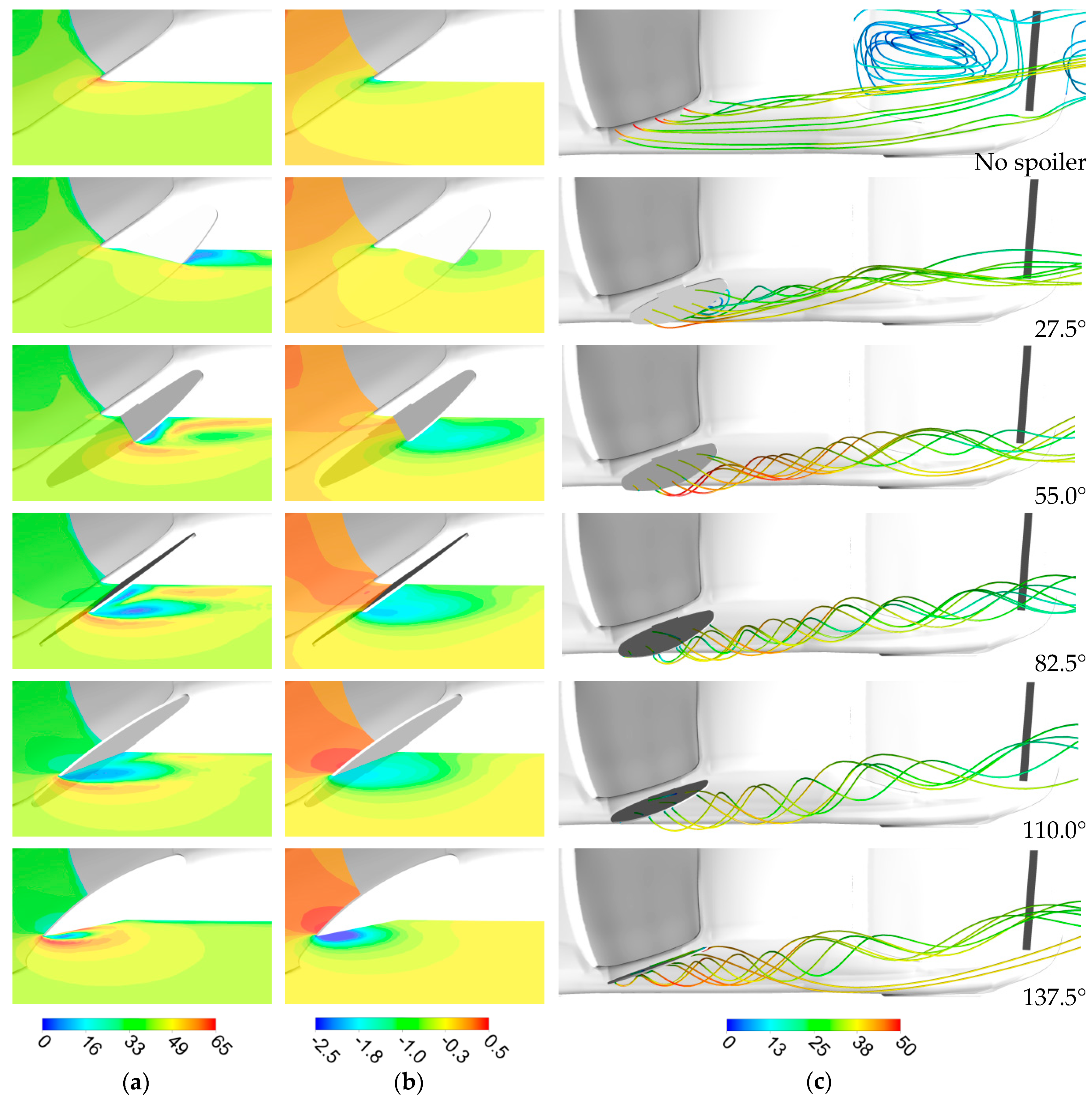
Six different cases were studied, which included the base case without the side spoiler and with the side spoiler inclined at 27.5°, 55.0°, 82.5°, 110.0°, and 137.5° (Figure 3). An obvious observation from Figure 3 is that the side spoiler increases the frontal area of the car, which indicates that it could be used as an airbrake. In Figure 3, it can also be seen that the area of the pressure build-up on the windshield and the spoiler increases together with the increase of the spoiler’s angle of inclination. At first, one might think that the area of pressure build-up as well as the value of the pressure itself should be highest when the spoiler is inclined perpendicular to the free stream, but because of the influence of the car body on the flow field, the most favorable conditions are when the spoiler is inclined perpendicular to the windshield. The highest pressure at the front of the spoiler and the lowest at the back of the spoiler make it possible to generate the greatest possible forces on the side spoiler itself. However, the angle of inclination determines in which direction this force acts and, moreover, it is also very important how the pressure distribution changes on the other parts of the car body. For this reason, the forces and moments generated on the side spoiler and the forces from the whole car body are presented separately in Figure 4 (numerical values are included in Appendix B).
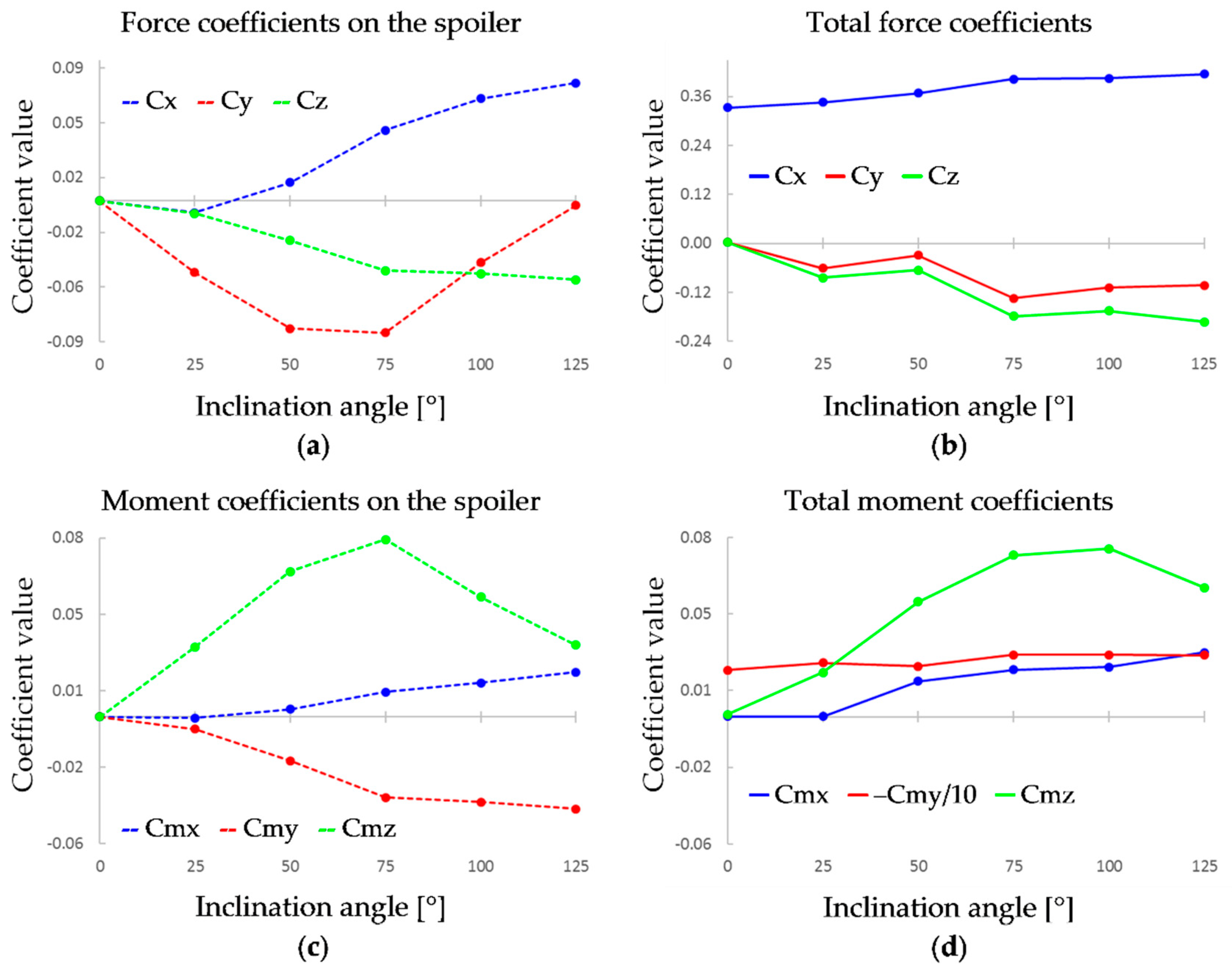
According to Figure 4a, the aerodynamic drag (Cx) generated on the spoiler itself increases together with the increase of its inclination angle and reaches peak values at 82.5° to 110.0°. A similar trend can be observed with the downforce (–Cz, negative lift); however, it decreases more rapidly after reaching its peak value at 82.5°. More complex changes occur with the characteristic of the side force (Cy), positive values of force are generated in the range between 0° to 55.0°, while the force shifts to the opposite direction at higher angles. The principle of operation at lower angles is similar to the one used in [26,27] to detach the flow at the leeward side of the car. This means that in the studied case, a larger overall side force would be obtained with a side spoiler at a high inclination angle on the left side of the car and at a low inclination angle on the right side.
The characteristics of the total values in Figure 4b look very similar to the ones in Figure 4a up to the angle equal to 110.0°, at which point the absolute values of the side force start to decrease, with the values of the downforce staying unchanged. In Figure 4c,d, one can see that the yawing moment (Cmz) increases together with the spoiler’s inclination angle and reaches its maximum at angles equal to 82.5° and 110.0°. This shows that at an angle equal to 110.0°, the side spoiler changes the car’s aerodynamic properties the most. Moreover, the generated side force and the yawing moment could be used to counter the influence of the crosswind, because the crosswind blowing from the side of the car where the spoiler is attached would generate a positive side force and a negative yawing moment. As mentioned earlier, a higher side force could be obtained with the side spoilers active on both sides of the car, but this would occur together with a loss of the yawing moment due to an opposite value of the moment generated by the spoilers on both sides of the car. Values of the pitching moment (Cmy) stay close to a constant level, which means that the balance of the car (the difference of the load on the front and the rear axle) is not subjected to a significant change. The pitching moment presented in Figure 4d was normalized to better fit the graph because it is ten orders of magnitude higher than the other two, which is due to the initial balance of the car. In Figure 4d, it can also be seen that a rolling moment (Cmx) is created, which means that the downforce increased on the side of the car where the spoiler was mounted.
When comparing the total moments and forces with the ones generated only on the spoiler, as presented in Figure 4, it should be noted that almost all of the overall value of the yawing and the rolling moments come from the spoiler itself, whereas a higher influence of the car body can be observed in the case of forces.
Visualizations in Figure 5a,b show how the flow field around the A-pillar is affected by the different inclination angles of the side spoiler. One can see that an increase of the inclination angle is followed by an increase in pressure difference on both sides of the spoiler and additional acceleration of the flow on its trailing edge. The only exception is for the lowest studied angle equal to 27.5° when the side spoiler generates a side force in the opposite direction than the other cases, which is caused by the overall increase in pressure behind the A-pillar due to the flow separation taking place behind the side spoiler. In Figure 5c, one can see the vortices created by the side spoiler, which are similar to the vortex created due to the presence of the A-pillar but stronger, especially for higher angles of inclination due to the increased pressure difference on both sides of the spoiler.
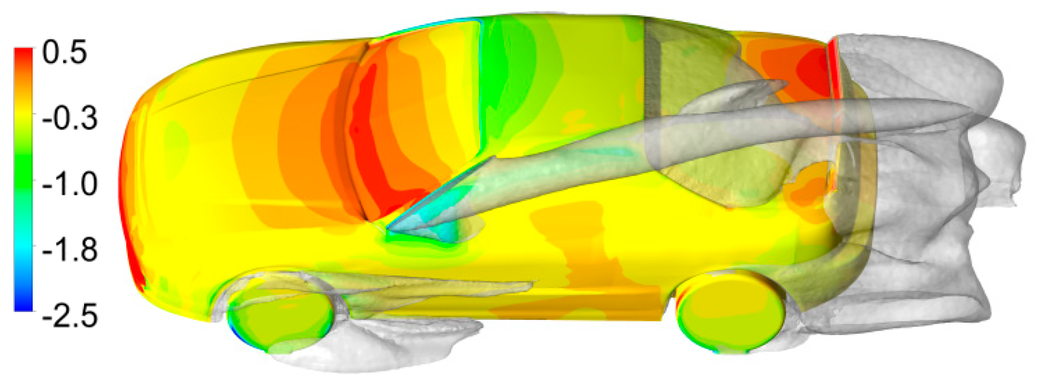
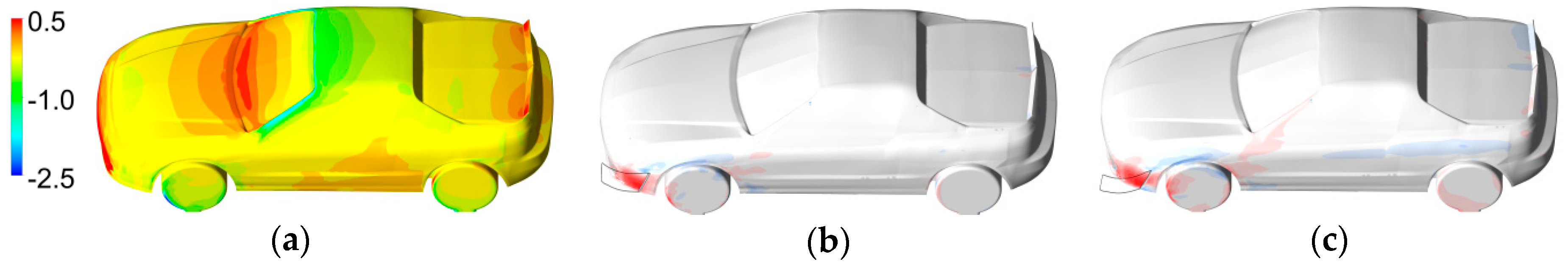
Figure 6a shows contours of the pressure coefficient for the base case without the side spoiler. To make the influence of the side spoiler clearer, contours in Figure 6b–f were included, which represent the results of subtraction of the pressure coefficient values in the base case and in each of the cases with a spoiler inclined at a corresponding angle. This way of presenting the results indicates which areas of the car body are affected most by the side spoiler. The addition of the side spoiler leads to an increase in pressure on the windshield and the roof, as well as a decrease in pressure on the side due to the vortex except for the highest angle of inclination (Figure 6f). An unexpected effect that the side spoiler entails is an increase in pressure on the trunk, which is the largest for the inclination equal to 110.0° (Figure 6e). This can be explained by the fact that the side spoiler on the quarter glass contributes to the increase of the detachment behind the car’s roof on its left side and reduces it on the opposite side, which results in an increase in the area of the stagnation zone and increases pressure on the right side of the trunk (Figure 7).
3.2. The Side Spoiler on a Front Bumper
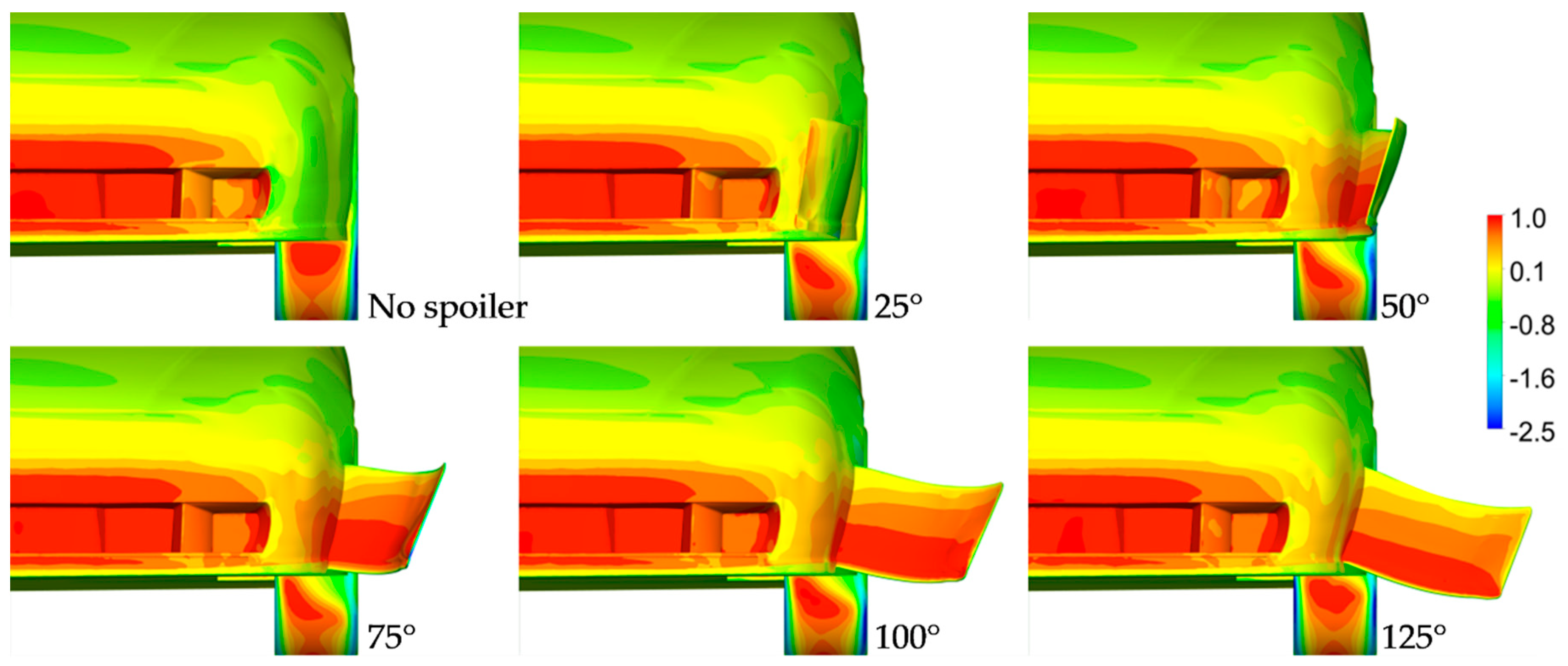
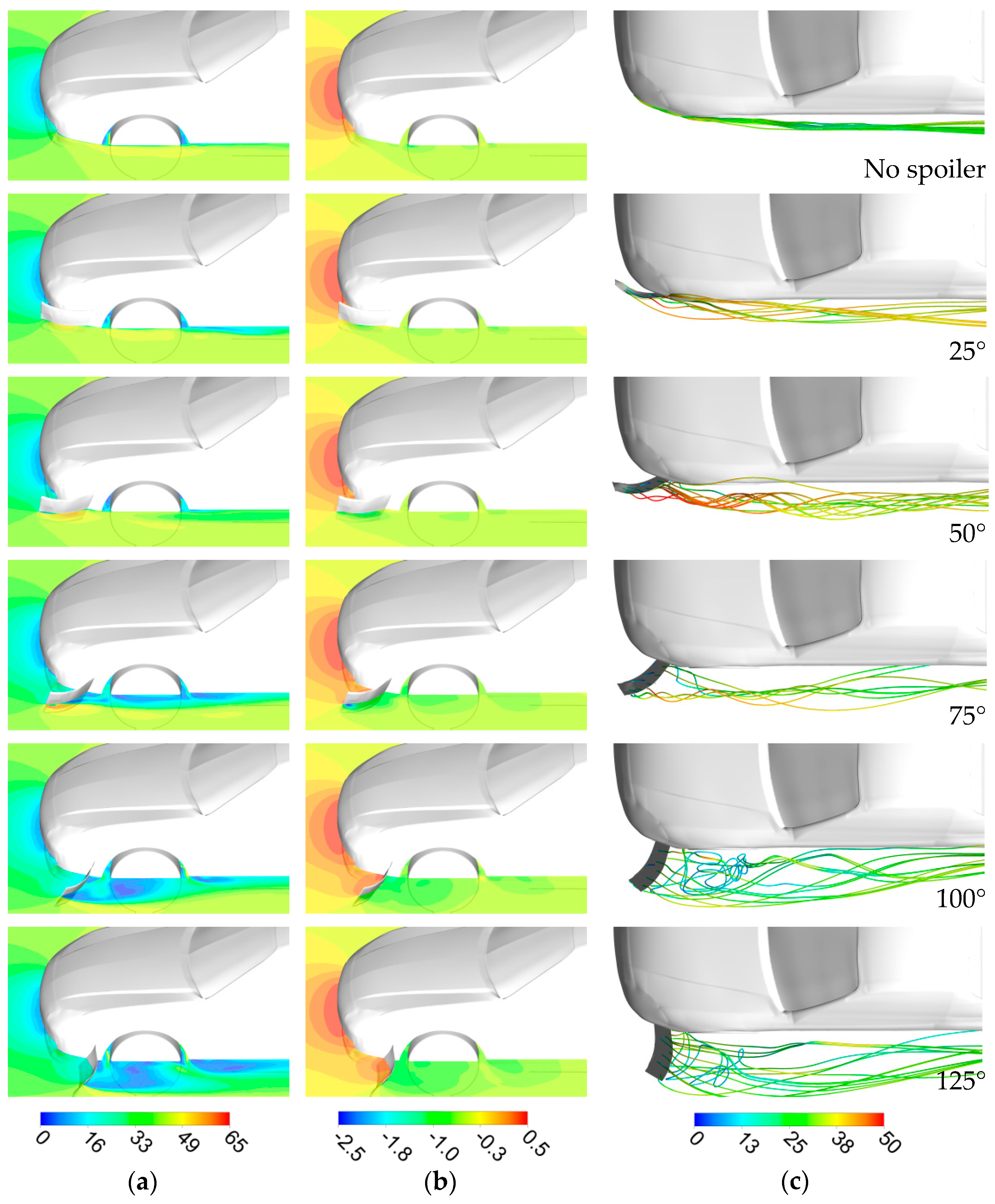
In the case of the side spoiler located at the front bumper, as before, six different cases were studied, with the side spoiler inclined from 25° up to 125°, as depicted in Figure 8. From Figure 8, it should be noted that the maximum safety limit is reached when the spoiler’s inclination angle reaches 50°. Above 50°, the side spoiler might interfere with other objects on the road. Higher angles were studied to gain knowledge on how effective a side spoiler in this location might be. In comparison with the previous case, the side spoiler at the bumper does not increase the car body’s frontal area, assuming that its inclination angle is less than 50°. Within this range of angles, the side spoiler stays hidden within the car’s silhouette.
Looking at the contours in Figure 8, it can be seen that the biggest differences in pressure distribution occur in the direct vicinity of the spoiler. Due to the fact that the spoiler is located in the area affected by the build-up of pressure taking place at the front of the bumper, the inside of the spoiler is subjected to high pressure even when the spoiler is inclined at a low angle. The pressure distribution on the outer side of the spoiler is subjected to bigger changes due to the fact that at lower angles, it faces the flow, whereas at higher angles, it is in the wake created by the side spoiler.
As in the case of the spoiler located on the quarter glass, the downforce and drag that the side spoiler generates both increase with the inclination angle (Figure 9a), with the exception of the lowest angle equal to 25°, which does not affect the drag. The maximum side force that the spoiler generates occurs between 50° and 75°; however, the total value of the side force generated on the whole car body (Figure 9b) is significantly higher at 75°, when it reaches its maximum. The yaw moment is the highest at 75° and 100° (Figure 9d). The rolling moment increases when the spoiler is moved above 25°, and its maximum value is similar to the case of the side spoiler located on the quarter glass; however, it is lower by approximately one third across the whole studied angle range. The pitching moment stays at a constant level. When studying the graphs in Figure 9, it can be concluded that there is no need to increase the inclination angle of the side spoiler located at the front bumper above 75°, because it does not lead to a significant improvement in efficiency.
Also interesting is that the value of the yawing moment at angles equal to 25°, 50°, and 75° is higher on the spoiler itself (Figure 9c) than the total value generated on the whole car body (Figure 9d). This suggests that there is a potential to improve the efficiency of this element by eliminating its negative influence arising from its interaction with the car body.
In Figure 10a, a detachment of the flow from the car body can be observed at angles above 75°, whereas at lower angles, the flow accelerates on the outer side of the spoiler and remains attached to the car body, which is consistent with the streamlines depicted in Figure 10c, where it is shown that the vortices created on the side spoiler inclined up to 50° stay attached to the side of the car. The highest drop in pressure on the outer side of the spoiler is observed at inclination angles equal to 50° and 75° (Figure 10b) due to the acceleration of the flow in that region. When a complete separation takes place, the pressure increases but is still lower than without the side spoiler.
The most significant differences in the pressure distribution (Figure 11) occur in the direct proximity of the spoiler, which can be observed as the pressure increases in front of it and decreases behind it. This area increases in size above the inclination angle equal to 75° and is the greatest at 125° (Figure 11f) when it stretches up to the A-pillar. It can be clearly seen that this area is much more confined in comparison with Figure 7 representing the change of pressure distribution for the case of the spoiler located at the quarter glass. It should be noted that at the angles of inclinations equal to 25° and 50° (Figure 11a,b), the pressure increases exactly between the side spoiler and the front wheel. This occurs because the inclination angle is too small to detach the flow, which leads to a pressure build-up in that region. This effect lowers the efficiency on the side spoiler and decreases the side force, as well as the yawing moment, which can be seen in Figure 9b as the absolute value of the side force decreases at an angle equal to 50°. Even more important is that the increase in pressure on the car body in front of the spoiler has the same effect and occurs on an even larger area. For this reason, the yawing moment generated on the whole car body is lower than the yawing moment generated on the side spoiler itself (Figure 9c,d). To solve this problem, the side spoiler could be either moved to the front or its rotation axis could be switched from the trailing edge of the spoiler plate to its leading edge to ensure that the activation of the spoiler decreases pressure on the side of the car body.
3.3. Cases Chosen for Different Yaw Conditions
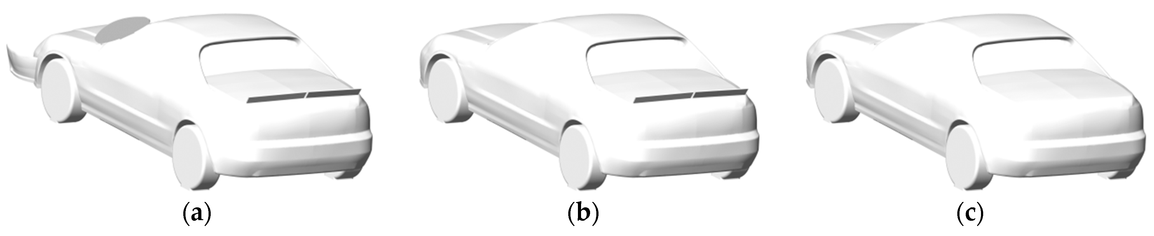
Three car body geometries were chosen for comparison across different yaw angles, a model with two additional side spoilers (Figure 12a), the base case model (Figure 12b), and a model with the spoiler removed on the trunk (Figure 12c). This set of cases makes it possible to compare how a typical aerodynamic enhancement, such as a rear spoiler placed on a car’s trunk, can improve the aerodynamic properties of a car in comparison with an unconventional method, such as the addition of side spoilers. The angle of inclination of the side spoilers was kept the same across all studied yaw angles, the side spoiler at the quarter glass was inclined at 110°, and the side spoiler at the bumper was inclined at 50°. In the case of the spoiler at the quarter glass, it is possible that adjusting its angle of inclination would be beneficial, and the angle should be decreased with an increase of the yaw angle. In the case of the side spoiler located on the quarter glass, the most efficient variant investigated at a zero yaw angle was selected (inclination angle equal to 110°), and in the case of the spoiler located at the front bumper, the highest inclination angle deemed acceptable was equal to 50° as this meant that the side spoiler did not significantly protrude outside the car body.
The aerodynamic properties for each case at a zero yaw angle are presented in Table 2. One can see that the base case model in comparison with the clean case model has an increased downforce due to the reduction of the lift force on the rear axle by half. When both of the side spoilers are mounted onto the car body, the effects of the asymmetrical loads can be observed, such as the side force, the rolling moment, and the yawing moment. In comparison with the base case, the drag coefficient increases by 48%, which means that these devices could be used as efficient airbrakes, especially as this value would be even higher if these devices were mounted on both sides. The downforce is also increased, approximately twice as much as due to the addition of the spoiler on the trunk and, at the same time, the balance of the car was kept almost the same with the value of the pitching moment changing only by 7%.
The interaction between the two side spoilers should also be considered. They are located at different heights, so there is no risk that one will be in the aerodynamic wake of the other; however, data in Table 2 suggests that an interaction between these two spoilers is taking place. When both of these spoilers are mounted together in the combined case, the aerodynamic forces on the spoilers themselves are almost equal to the sum of forces that they generate when they are mounted separately. This also applies when the total values generated on the whole car body are considered for the drag and for the lift force. However, in the case of the total side force, it is almost twice as high when the two spoilers are combined together in comparison with the cases when they are used separately. The interaction between these two spoilers is depicted in Figure 13. One can see that, when both side spoilers are present, more of the flow is sucked upwards, towards the wake behind the spoiler on the quarter glass, which leads to a decrease in pressure on the side of the car. However, pressure is decreased in front as well as behind the center of gravity, which according to Table 2, leads to a decrease of the yawing moment for the combined case by approximately 14% in comparison with the yawing moment generated when the side spoilers were mounted separately.
To conclude, the side spoilers mounted together work well, and it would appear that there is room to increase their efficiency even more if the interactions between them are taken into account.
3.4. Results at Different Yaw Angles
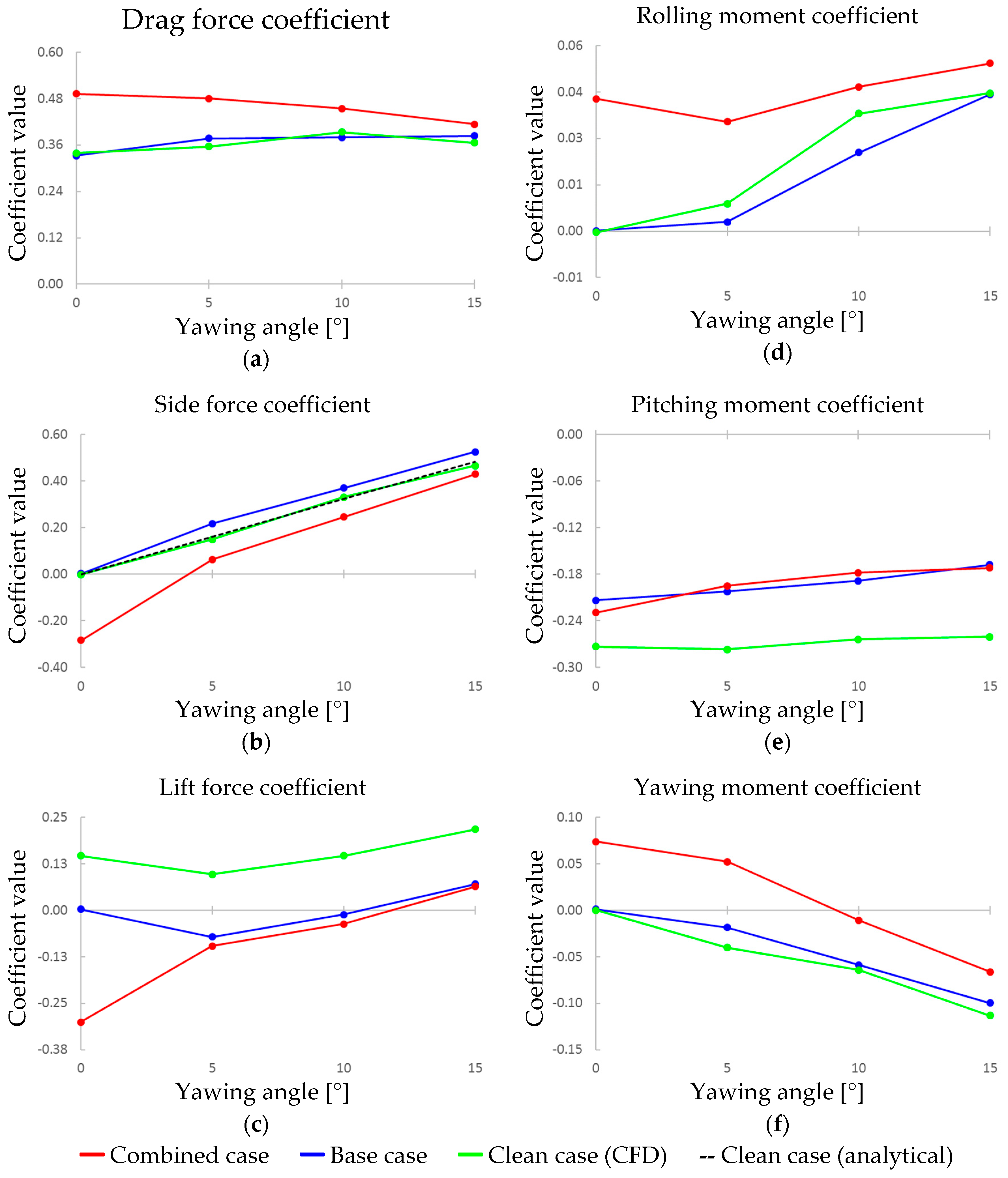
The investigations of the car body geometries presented in Figure 12 were performed for yaw angles between 0° and 15°. The characteristics of the aerodynamic forces and moments obtained are presented in Figure 14, in which the results can be compared for the base case (car body with a spoiler on the trunk), for the combined case (includes two side spoilers), and for the clean case which does not have any aerodynamic devices.
The configurations with and without the rear spoiler have similar characteristics. As pointed out in the previous section, the biggest difference between them is the increase of downforce due to the addition of the rear spoiler, which also results in a decrease of the pitching moment because of a smaller difference of the loads on the front and rear axles. According to data presented in [39], where the influence of rear spoilers was studied, the attachment of a rear spoiler was followed by a reduction of the lift force and the yawing moment as well as an increase of the side force and the rolling moment. These findings are consistent with the results of numerical calculations for the car body geometry with and without the rear spoiler, as presented in Figure 14.
To include more than just CFD results in the data presented in Figure 14, a formula proposed in [24] was used that makes it possible to calculate the side force derivative for a three-box car body type:
where vehicle dimensions such as height (H), boot height (Hte), frontal area (A), and length (L) are considered. Taking into account all of those dimensions makes it possible to predict the side force more accurately; however, as identified in [24], vehicle height has the most dominant influence on the side force. The side force derivative in Equation (4) represents the change of side force coefficient with the yaw angle. It was concluded in [24] that the yaw moment could not be predicted with a similar formula due to its high sensitivity to the distribution of the side force load. The case without the rear spoiler was chosen for comparison with the results from the analytical calculations and the ones obtained with the use of CFD, and, in Figure 14b, one can see that the formula matches the CFD results very closely throughout the studied yaw angle range.
The key findings of our paper refer to the results of the flow around a car body equipped with side spoilers. One can see, from the results of the side force (Figure 14b) for the combined case where the two side spoilers were mounted, that the side spoilers make it possible to generate a side force that counters the side force generated by the crosswind up to the yaw angle equal to 4° and, more importantly, a yawing moment, which negates the effects of the crosswind up to an angle equal to 9° (Figure 14f).
In Figure 14, when considering the influence of the side spoilers, one can see that most of the aerodynamic characteristics are shifted by a constant value. The most notable exception is the lift force coefficient characteristic (Figure 14c), which shows that the side spoilers used are significantly less effective at increasing the total value of the car’s downforce at non-zero yaw angles. In addition to this, the drag characteristics (Figure 14a) for all three cases converge together as the yaw angle increases. This occurs due to the fact that, at a zero yaw angle, the side spoilers generated additional drag because of the increase of the frontal area that they created. With the increase of the yaw angle and the constant angle at which the side spoilers are inclined, the side spoilers create less and less drag, and, for this reason, the drag generated by the car body starts to dominate the total values of the drag. This also applies to the rolling moment characteristics (Figure 14d), which converge together due to the decrease of the downforce that each side spoiler generates at the increased yaw angle.
The characteristic of the change in the car’s balance is not modified by the side spoilers in comparison with the other cases (Figure 14e), which is positive because the driver would not suddenly become confused by it. This would be especially important when driving on a curve where a sudden change in the car’s balance might cause it to oversteer or understeer. Apart from the forces directly counteracting the crosswind, another positive effect is a slight increase of the downforce across the whole studied yaw angle range; however, as noted earlier, the side spoilers were much less effective in generating additional downforce at non-zero yaw angles.
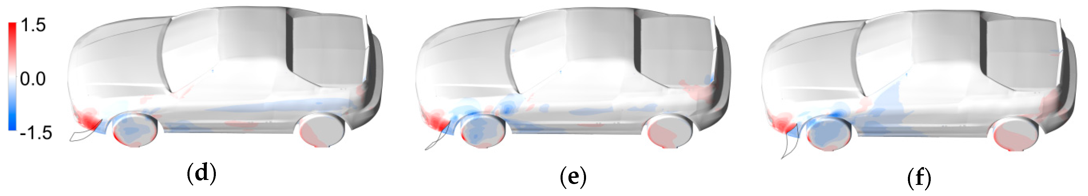
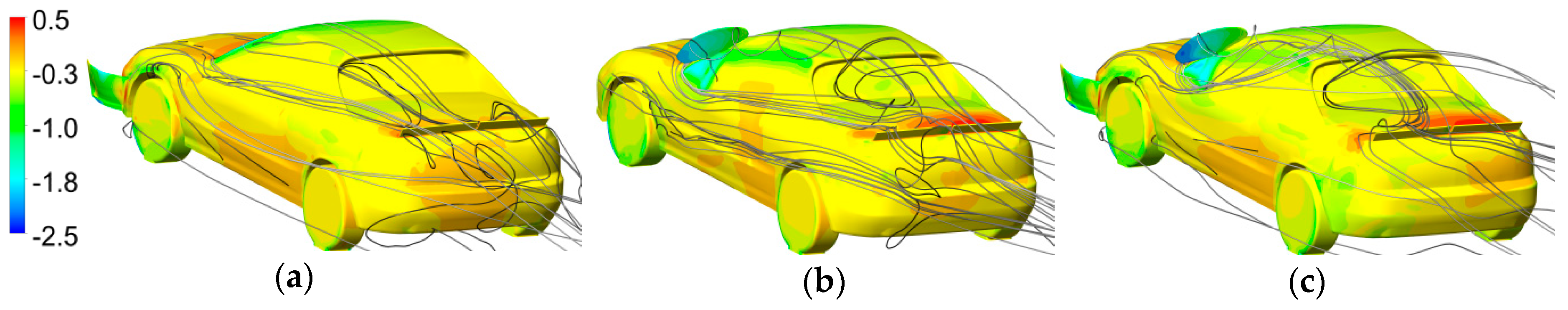
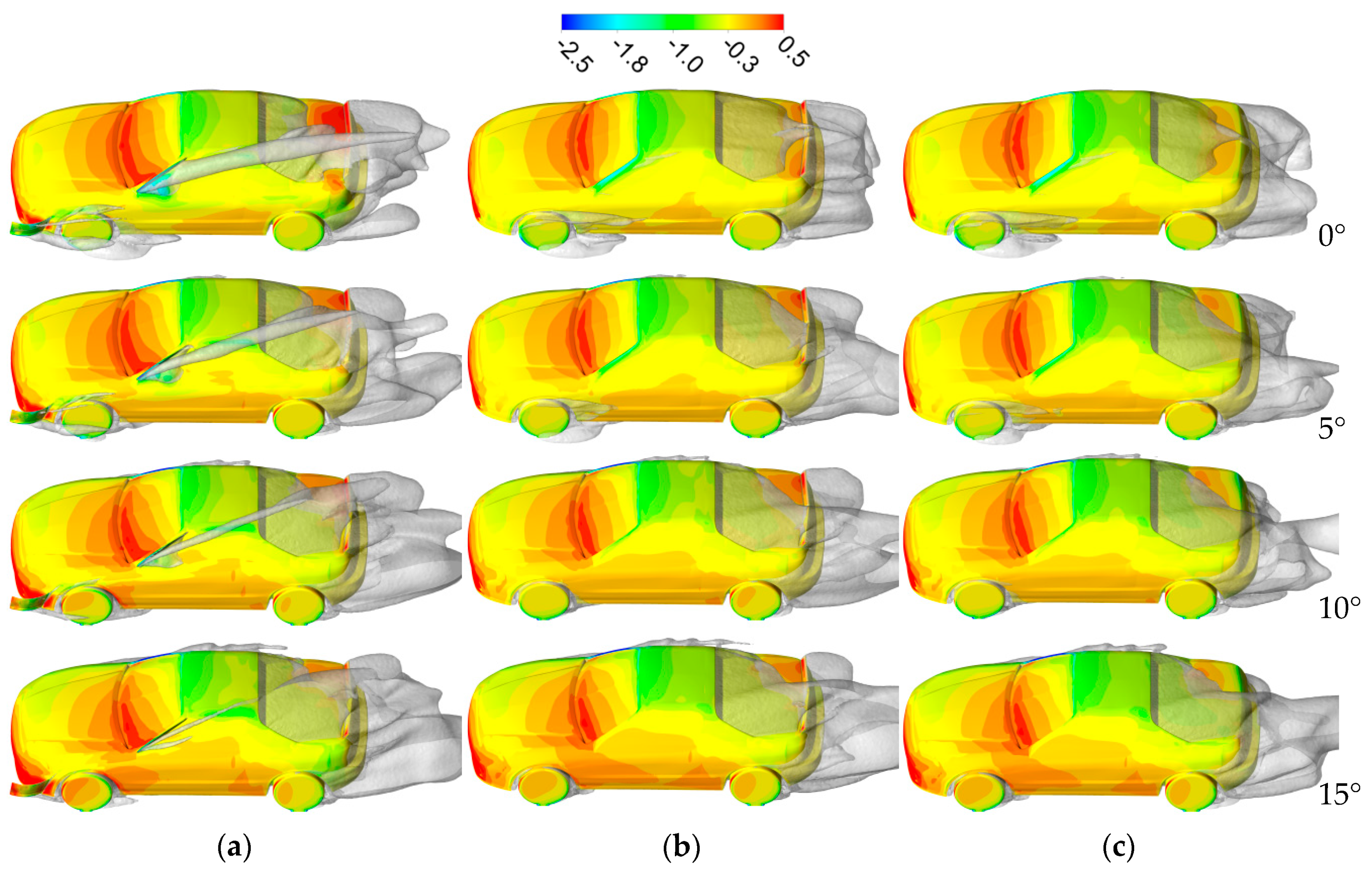
Contours of pressure coefficient on the car body for each of the three studied cases are presented in Figure 15. This figure also includes iso-surfaces of total pressure equal to zero, which give information on how the 3D features corresponding to the flow losses are affected by the non-zero yaw angle flow. As mentioned before, the side spoilers are located on the windward side of the car (they can be seen at the bottom of the car body in Figure 15). The pressure distribution on the windshield and the shape of the iso-surfaces in the passenger’s cabin wake in Figure 15 at a zero yaw angle flow for a car with side spoilers (the combined case) look similar as for the car without side spoilers but at non-zero yaw angles. The vortex created on the side spoiler at the quarter glass becomes weaker at higher yaw angles because the direction of the flow becomes aligned to it. For this reason, consideration should be given to modify its inclination angle to the optimal one at a given yaw angle, which should improve its efficiency across the range of non-zero yaw angles. The side spoiler on the quarter glass contributes to the increase of the detachment behind the car’s roof on its left side and reduces it on its right side, which results in an increase in pressure on the leeward side of the trunk, but only at a zero yaw angle. Where the pressure distribution on the side of the car is concerned, the introduction of the side spoiler on the quarter glass decreases the pressure the most in direct proximity of the side spoiler, which applies across the whole studied yaw angle range. However, in the case of the spoiler mounted on the bumper at angles equal to 10° and 15°, one can see that the pressure in the region of the front tire is higher. When comparing the base case and the clean case where there is no spoiler on the trunk, the most noticeable change is the decrease in pressure on the trunk, which results in a decreased downforce on the rear axle. This also leads to a decrease in pressure on the windward side of the trunk when the car is subjected to non-zero yaw angle flows.
The increase of drag from using the presented side spoilers could be perceived as a negative consequence, which means that this kind of mechanism should be treated as an emergency device and used only for short periods of time (several seconds), otherwise fuel consumption would be increased. However, if these elements were used symmetrically on both sides of the car, then they could be used as an airbrake which would not shift the balance of the car so much to the rear as when a rear wing is used in braking mode [34], making it a good airbrake during cornering. Moreover, the rolling moment and side force generated by the side spoilers are other properties that could be used when a car is driving on a curve; therefore, the use of these elements could improve driving safety. The generated rolling moment would increase the downforce on the car’s wheels on the inward side of the curve, whereas the side force would decrease the centrifugal force that a cornering car is subjected to.
In order to efficiently use the presented side spoilers during a gust of wind or cornering, their operation should be fully automatic. This would make them especially suitable for fully autonomous vehicles. Apart from a steering mechanism that would enable a quick adjustment of the inclination angle of the side spoilers, such a device would also need to rely on a set of sensors that would deliver information about the kind of force or moment that needs to be generated on the car body to improve driving stability. The ability to detect the need to perform a rapid maneuver or to detect a gust of wind that is about to hit the car would also increase its capabilities, because the autonomous system could either decide to activate some of the active aerodynamic elements beforehand or put them on standby to ensure that they can be activated as soon as possible.
4. Conclusions
A new location for a side spoiler was presented, with the side spoiler mounted on the quarter glass, which proved to be very efficient. Its operation was studied when it was the only additional element attached to the car body and when it was accompanied by another side spoiler mounted on the side of a fender, which is a more common location for attaching aerodynamic devices. The studied side spoilers were located on the windward side, whereas in other investigations, most of the focus was on the modifications of the leeward side of a vehicle. It was proven that side spoilers could significantly change the side force and the yawing moment coefficients over a wide range of yaw angles. Using these kinds of elements could enhance car safety during a steady-state crosswind.
The studied aerodynamic elements generated additional drag, which means that they can only be used for short periods of time to decrease a car’s sensitivity to a crosswind and therefore increase driving safety. Unfortunately, they cannot be used to improve fuel economy, which is affected by the increase in yaw angle. However, on the other hand, they provide an interesting alternative for the rear wing as an airbrake as well as a device that improves the downforce of a vehicle without shifting the balance of the car towards the rear axle. Another potential application is when it is necessary to perform a rapid turning maneuver, and the possibility of generating a yaw moment might prove to be beneficial for its successful completion.
Different car body types should be studied to investigate their influence on the operation of the side spoilers and the interaction between each of the used side spoilers to improve their efficiency depending on the desired force or moment that they are expected to generate. Such a study should be undertaken because this paper presented that side spoilers can significantly influence the flow downstream, even in locations that are not directly behind the side spoilers. With a larger result dataset available, a best practice guide for designing side spoilers could be prepared to aid car designers. This should also lead to establishing the most efficient shapes of side spoilers mounted at each location, and also whether the same shape could be used for different kinds of car bodies or if it should be tailored depending on a given car body shape.
The use of active side spoilers could lead to benefits when combined with autonomous vehicles. A driver’s reflexes would be too slow for efficient use, and manual operation would pose an additional distraction. An especially important factor is that a change in the design of future vehicles could facilitate the inclusion of these kinds of aerodynamic elements.
Despite all the advantages, there are many challenges that need to be overcome to implement such devices. The algorithm used for controlling the steering mechanism of the side spoilers when the car is subjected to a crosswind would have to take into account the current yaw angle that the crosswind creates and align the side spoilers accordingly. It should also be investigated whether the value of force and moment coefficients that are influenced by side spoilers differ depending on the speed. Future investigations on this matter should include unsteady calculations that would take into account the dynamic phenomena that take place when the side spoilers are activated and while they are being ejected from the car body. The most complete analysis of the efficiency of this mechanism would involve performing simulations combining aerodynamics and vehicle motion.
Author Contributions
Conceptualization, K.K. and J.P.; methodology, K.K. and J.P.; software, K.K.; validation, K.K.; formal Analysis, K.K. and J.P.; investigation, K.K. and J.P.; resources, K.K. and J.P.; data curation, K.K.; writing—original draft preparation, K.K.; writing—review and editing, J.P.; visualization, K.K.; supervision, J.P.; project administration, J.P.; funding acquisition, J.P.
Funding
This project was funded by the National Centre for Research and Development (Narodowe Centrum Badań i Rozwoju), grant number PBS3/B6/34/2015, “The active system of car body oscillation damping”.
Conflicts of Interest
The authors declare no conflict of interest. The sponsors had no role in the design, execution, interpretation, or writing of the study.
Abbreviations
The following abbreviations are used in this manuscript:
| CFD | Computational Fluid Dynamics |
| NASCAR | National Association for Stock Car Auto Racing |
| RANS | Reynolds-Averaged Navier Stokes |
| SST | Shear Stress Transport |
Appendix A. The Main Dimensions of the Spoilers and the Car Body
Figure A1.
Car body and spoilers (marked in blue) dimensions.

Appendix B. Tables with the Values Used in Each Graph

Table A1.
Breakdown of the aerodynamic loads generated on the car body and the side spoiler mounted on the quarter glass and inclined at different angles, presented on graphs in Figure 4.
Table A1.
Breakdown of the aerodynamic loads generated on the car body and the side spoiler mounted on the quarter glass and inclined at different angles, presented on graphs in Figure 4.
| Angle [°] | Cx | Cy | Cz | Cmx | Cmy | Cmz | ||||||
|---|---|---|---|---|---|---|---|---|---|---|---|---|
| Spoiler | Total | Spoiler | Total | Spoiler | Total | Spoiler | Total | Spoiler | Total | Spoiler | Total | |
| 0.0 | – | 0.333 | – | 0.002 | – | 0.002 | 0.000 | 0.000 | 0.000 | –0.214 | 0.000 | 0.001 |
| 27.5 | 0.011 | 0.370 | 0.014 | 0.058 | –0.025 | –0.088 | 0.005 | 0.009 | –0.001 | –0.239 | 0.002 | 0.007 |
| 55.0 | 0.038 | 0.410 | 0.004 | 0.007 | –0.063 | –0.160 | 0.019 | 0.025 | –0.002 | –0.241 | 0.011 | 0.025 |
| 82.5 | 0.051 | 0.440 | –0.032 | –0.063 | –0.066 | –0.218 | 0.027 | 0.037 | 0.000 | –0.232 | 0.021 | 0.024 |
| 110.0 | 0.048 | 0.448 | –0.066 | –0.121 | –0.042 | –0.198 | 0.027 | 0.036 | 0.004 | –0.186 | 0.025 | 0.034 |
| 137.5 | 0.037 | 0.433 | –0.097 | –0.072 | –0.007 | –0.200 | 0.024 | 0.033 | 0.007 | –0.224 | 0.028 | 0.027 |
Table A2.
Breakdown of the aerodynamic loads generated on the car body and the side spoiler mounted on the front bumper and inclined at different angles, presented on graphs in Figure 9.
Table A2.
Breakdown of the aerodynamic loads generated on the car body and the side spoiler mounted on the front bumper and inclined at different angles, presented on graphs in Figure 9.
| Angle [°] | Cx | Cy | Cz | Cmx | Cmy | Cmz | ||||||
|---|---|---|---|---|---|---|---|---|---|---|---|---|
| Spoiler | Total | Spoiler | Total | Spoiler | Total | Spoiler | Total | Spoiler | Total | Spoiler | Total | |
| 0 | – | 0.333 | – | 0.002 | – | 0.002 | 0.000 | 0.000 | 0.000 | –0.214 | 0.000 | 0.001 |
| 25.0 | –0.007 | 0.346 | –0.046 | –0.061 | –0.008 | –0.084 | 0.000 | 0.000 | –0.006 | –0.247 | 0.032 | 0.020 |
| 50.0 | 0.012 | 0.368 | –0.081 | –0.030 | –0.025 | –0.065 | 0.004 | 0.016 | –0.020 | –0.230 | 0.067 | 0.053 |
| 75.0 | 0.045 | 0.403 | –0.084 | –0.135 | –0.044 | –0.179 | 0.011 | 0.021 | –0.037 | –0.284 | 0.081 | 0.074 |
| 100.0 | 0.065 | 0.404 | –0.039 | –0.109 | –0.046 | –0.166 | 0.016 | 0.023 | –0.039 | –0.282 | 0.055 | 0.077 |
| 125.0 | 0.075 | 0.415 | –0.003 | –0.103 | –0.050 | –0.193 | 0.020 | 0.029 | –0.042 | –0.281 | 0.033 | 0.059 |
Table A3.
Aerodynamic loads generated on the car body with different aerodynamic configurations, presented on graphs in Figure 14.
Table A3.
Aerodynamic loads generated on the car body with different aerodynamic configurations, presented on graphs in Figure 14.
| Combined case | Base case | ||||||||||||
| Yaw [°] | Cx | Cy | Cz | Cmx | Cmy | Cmz | Yaw [°] | Cx | Cy | Cz | Cmx | Cmy | Cmz |
| 0 | 0.492 | –0.285 | –0.301 | 0.040 | –0.230 | 0.074 | 0 | 0.333 | 0.002 | 0.002 | 0.000 | –0.214 | 0.001 |
| 5 | 0.480 | 0.064 | –0.096 | 0.033 | –0.195 | 0.052 | 5 | 0.377 | 0.218 | –0.072 | 0.003 | –0.202 | –0.019 |
| 10 | 0.454 | 0.246 | –0.037 | 0.044 | –0.178 | –0.011 | 10 | 0.379 | 0.371 | –0.012 | 0.024 | –0.189 | –0.059 |
| 15 | 0.414 | 0.430 | 0.063 | 0.051 | –0.172 | –0.066 | 15 | 0.383 | 0.527 | 0.071 | 0.041 | –0.168 | –0.100 |
| Clean case (CFD) | Clean case (analytical) | ||||||||||||
| Yaw [°] | Cx | Cy | Cz | Cmx | Cmy | Cmz | Yaw [°] | Cx | Cy | Cz | Cmx | Cmy | Cmz |
| 0 | 0.339 | –0.001 | 0.147 | 0.000 | –0.273 | 0.000 | 0 | – | 0.000 | – | – | – | – |
| 5 | 0.356 | 0.150 | 0.096 | 0.008 | –0.277 | –0.040 | 5 | – | 0.161 | – | – | – | – |
| 10 | 0.394 | 0.331 | 0.147 | 0.035 | –0.264 | –0.064 | 10 | – | 0.323 | – | – | – | – |
| 15 | 0.366 | 0.467 | 0.218 | 0.042 | –0.261 | –0.113 | 15 | – | 0.484 | – | – | – | – |
References
- Howell, J.P. The side load distribution on a Rover 800 saloon car under crosswind conditions. J. Wind Eng. Ind. Aerodyn. 1996, 60, 139–153. [Google Scholar] [CrossRef]
- Carlino, G.; Cardano, D.; Cogotti, A. A New Technique to Measure the Aerodynamic Response of Passenger Cars by a Continuous Flow Yawing; SAE Technical Paper 2007-01-0902; SAE: Warrendale, PA, USA, 2007. [Google Scholar]
- Pfeiffer, J.; King, R. Robust control of drag and lateral dynamic response for road vehicles exposed to cross-Wind gusts. Exp. Fluids 2018, 59, 45. [Google Scholar] [CrossRef] [Green Version]
- Volpe, R.; Ferrand, V.; Da Silva, A.; Le Moyne, L. Forces and flow structures evolution on a car body in a sudden crosswind. J. Wind Eng. Ind. Aerodyn. 2014, 128, 114–125. [Google Scholar] [CrossRef] [Green Version]
- Kee, J.D.; Rho, J.H.; Kim, K.H.; Lee, D.H. High speed driving stability of passenger car under crosswind effects. Int. J. Automot. Technol. 2014, 15, 741–747. [Google Scholar] [CrossRef]
- D’Hooge, A.; Rebbeck, L.; Palin, R.; Murphy, Q.; Gargoloff, J.; Duncan, B. Application of Real-World Wind Conditions for Assessing Aerodynamic Drag for On-Road Range Prediction; SAE Technical Paper 2015-01-1551; SAE: Warrendale, PA, USA, 2015. [Google Scholar]
- Howell, J.; Forbes, D.; Passmore, M.; Page, G. The Effect of a Sheared Crosswind Flow on Car Aerodynamics. SAE Int. J. Passeng. Cars Mech. Syst. 2017, 10, 278–285. [Google Scholar] [CrossRef]
- Lewington, N.; Ohra-Aho, L.; Lange, O.; Rudnik, K. The Application of a One-Way Coupled Aerodynamic and Multi-Body Dynamics Simulation Process to Predict Vehicle Response during a Severe Crosswind Event; SAE Technical Paper 2017-01-1515; SAE: Warrendale, PA, USA, 2017. [Google Scholar]
- Forbes, D.C.; Page, G.J.; Passmore, M.A.; Gaylard, A.P. A Fully Coupled, 6 Degree-of-Freedom, Aerodynamic and Vehicle Handling Crosswind Simulation using the DrivAer Model. SAE Int. J. Passeng. Cars Mech. Syst. 2016, 9. [Google Scholar] [CrossRef] [Green Version]
- Huang, T.; Gu, Z.; Feng, C.; Zeng, W. Transient aerodynamics simulations of a road vehicle in the crosswind condition coupled with the vehicle’s motion. Proc. Inst. Mech. Eng. Part D J. Automob. Eng. 2018, 232, 583–598. [Google Scholar] [CrossRef]
- Okada, Y.; Nouzawa, T.; Okamoto, S.; Fujita, T.; Kamioka, T.; Tsubokura, M. Unsteady Vehicle Aerodynamics during a Dynamic Steering Action: 1st Report, On-Road Analysis; SAE Technical Paper 2012-01-0446; SAE: Warrendale, PA, USA, 2012. [Google Scholar]
- Tsubokura, M.; Ikawa, Y.; Nakashima, T.; Okada, Y.; Kamioka, T.; Nouzawa, T. Unsteady Vehicle Aerodynamics during a Dynamic Steering Action: 2nd Report, Numerical Analysis. SAE Int. J. Passeng. Cars Mech. Syst. 2012, 5, 340–357. [Google Scholar] [CrossRef]
- Windsor, S. Real world drag coefficient is it wind averaged drag? In Proceedings of the The International Vehicle Aerodynamics; Woodhead Publishing: Sawston\London, UK, 2014. [Google Scholar]
- Howell, J. Aerodynamic Drag of Passenger Cars at Yaw. SAE Int. J. Passeng. Cars Mech. Syst. 2015, 8, 306–316. [Google Scholar] [CrossRef]
- Iinuma, Y.; Taniguchi, K.; Oshima, M. Aerodynamics Development for a New EV Hatchback Considering Crosswind Sensitivity; SAE Technical Paper 2018-01-0715; SAE: Warrendale, PA, USA, 2018. [Google Scholar]
- Fu, C.; Bounds, C.P.; Selent, C.; Uddin, M. Turbulence modeling effects on the aerodynamic characterizations of a NASCAR Generation 6 racecar subject to yaw and pitch changes. Proc. Inst. Mech. Eng. Part D J. Automob. Eng. 2019, 233, 095440701982647. [Google Scholar] [CrossRef]
- Jacuzzi, E.; Barrier, A.; Granlund, K.O. NASCAR Race Vehicle Wake Modification via Passive Blown Ducts and its Effect on Trailing Vehicle Drag. In Proceedings of the 2018 AIAA Aerospace Sciences Meeting, Kissimmee, FL, USA, 8–12 January 2018; American Institute of Aeronautics and Astronautics: Reston, VA, USA, 2018. [Google Scholar]
- Jacuzzi, E.; Aleman Chona, M.; Granlund, K.O. Improvements in NASCAR Race Vehicle Side Force and Yawing Moment Stability in Race Conditions Using Active or Passive Blowing. In Proceedings of the AIAA Scitech 2019 Forum, San Diego, CA, USA, 7–11 January; American Institute of Aeronautics and Astronautics: Reston, VA, USA, 2019. [Google Scholar]
- Fu, C.; Uddin, M.; Robinson, A.C. Turbulence modeling effects on the CFD predictions of flow over a NASCAR Gen 6 racecar. J. Wind Eng. Ind. Aerodyn. 2018, 176, 98–111. [Google Scholar] [CrossRef]
- Jacuzzi, E.; Granlund, K. Passive flow control for drag reduction in vehicle platoons. J. Wind Eng. Ind. Aerodyn. 2019, 189, 104–117. [Google Scholar] [CrossRef]
- Nelson, G.; Roush, J.; Eaker, G.; Wallis, S. The Development and Manufacture of a Roof Mounted Aero Flap System for Race Car Applications; SAE Technical Paper 942522; SAE: Warrendale, PA, USA, 1994. [Google Scholar]
- Johansson, M.O.; Katz, J. Lateral Aerodynamics of a Generic Sprint Car Configuration; SAE Technical Paper 2002-01-331; SAE: Warrendale, PA, USA, 2002; pp. 2331–2338. [Google Scholar]
- Willumeit, H.P.; Muller, K.; Dodlbacher, G.; Matheis, A. Method To Correlate Vehicular Behaviour and Driver’S Judgement Under Side Wind Disturbances. Veh. Syst. Dyn. 1988, 17, 508–524. [Google Scholar] [CrossRef]
- Howell, J.; Panigrahi, S. Aerodynamic Side Forces on Passenger Cars at Yaw; SAE Technical Paper 2016-01-1620; SAE: Warrendale, PA, USA, 2016. [Google Scholar]
- Nakasato, K.; Tsubokura, M.; Ikeda, J.; Onishi, K.; Ota, S.; Takase, H.; Akasaka, K.; Ihara, H.; Oshima, M.; Araki, T. Coupled 6DoF Motion and Aerodynamic Crosswind Simulation Incorporating Driver Model. SAE Int. J. Passeng. Cars Mech. Syst. 2017, 10, 662–670. [Google Scholar] [CrossRef]
- Okumura, K.; Kuriyama, T.; Kato, A.; Hayashi, Y. Development of crosswind spoiler. JSAE Rev. 1996, 17, 293–299. [Google Scholar] [CrossRef]
- Sumitani, K.; Yamada, M. Development of “Aero Slit” Improvement of Aerodynamic Yaw Characteristics for Commercial Vehicles; SAE Technical Paper 890372; SAE: Warrendale, PA, USA, 1989. [Google Scholar]
- Kumar, A.; Sebben, S.; Sallstrom, E.; Jacobson, B.J.H.; Broniewicz, A.; Kumar, A.; Sebben, S.; Sallstrom, E.J.H.; Jacobson, B.; Broniewicz, A. Analysis of Subjective Qualitative Judgement of Passenger Vehicle High Speed Drivability due to Aerodynamics. Energies 2019, 12, 2839. [Google Scholar] [CrossRef] [Green Version]
- Kataoka, T.; China, H.; Nakagawa, K.; Yanagimoto, K.; Yoshida, M. Numerical Simulation of Road Vehicle Aerodynamics and Effect of Aerodynamic Devices. SAE Trans. 1991, 100, 722–734. [Google Scholar]
- Katz, J. Automotive Aerodynamics; Wiley: Hoboken, NJ, USA, 2016; ISBN 1119185726. [Google Scholar]
- Kurec, K.; Remer, M.; Mayer, T.; Tudruj, S.; Piechna, J. Flow control for a car-Mounted rear wing. Int. J. Mech. Sci. 2019, 152, 384–399. [Google Scholar] [CrossRef]
- Kurec, K.; Remer, M.; Broniszewski, J.; Bibik, P.; Tudruj, S.; Piechna, J. Advanced Modeling and Simulation of Vehicle Active Aerodynamic Safety. J. Adv. Transp. 2019, 2019, 7308590. [Google Scholar] [CrossRef] [Green Version]
- Broniszewski, J.; Piechna, J. A fully coupled analysis of unsteady aerodynamics impact on vehicle dynamics during braking. Eng. Appl. Comput. Fluid Mech. 2019, 13, 623–641. [Google Scholar] [CrossRef]
- Kurec, K.; Remer, M.; Piechna, J. The influence of different aerodynamic setups on enhancing a sports car’s braking. Int. J. Mech. Sci. 2019, 164, 105140. [Google Scholar] [CrossRef]
- Theory Guide; ANSYS® Academic Associate CFD, Release 16.2, Help System; ANSYS, Inc.: Canonsburg, PA, USA, 2016.
- Heft, A.I.; Indinger, T.; Adams, N.A. Introduction of a New Realistic Generic Car Model for Aerodynamic Investigations; SAE Technical Paper 2012-01-0168; SAE: Warrendale, PA, USA, 2012. [Google Scholar]
- Meshing User’s Guide; ANSYS® Academic Associate CFD, Release 16.2, Help System; ANSYS, Inc.: Canonsburg, PA, USA, 2016.
- Menter, F.R. Two-Equation eddy-Viscosity turbulence models for engineering applications. AIAA J. 1994, 32, 1598–1605. [Google Scholar] [CrossRef] [Green Version]
- Howell, J.; Baden Fuller, J. A Relationship between Lift and Lateral Aerodynamic Characteristics for Passenger Cars; SAE Technical Paper 2010-01-1025; SAE: Warrendale, PA, USA, 2010. [Google Scholar]
Figure 1.
(a) A side view of the Honda CR-X del Sol, blue color marks area of the side spoilers, and the red lines are the according rotational axes. Directions of the studied forces and moments are included, with the axis placed in the car’s center of gravity. (b) Isometric view and (c) front view of the car with side spoilers at a different angle of rotational (each marked in a different color to make it more clear). Forces and moments coefficients: Cx (Drag), Cy (Side), Cz (Lift), Cmx (Roll), Cmy (Pitch), Cmz (Yaw).

Figure 2.
(a) The computational domain, (b) mesh on the symmetry plane, (c) close-up on the mesh in the boundary layer region. Type of boundary conditions: ■ velocity inlet, ■ pressure outlet, ■ wall, ■ symmetry.
Figure 2.
(a) The computational domain, (b) mesh on the symmetry plane, (c) close-up on the mesh in the boundary layer region. Type of boundary conditions: ■ velocity inlet, ■ pressure outlet, ■ wall, ■ symmetry.

Figure 3.
Contours of pressure coefficient on the front of the car body.

Figure 4.
(a) Force coefficients on the spoiler, (b) total force coefficients, (c) moment coefficients on the spoiler, (d) total moment coefficients.
Figure 4.
(a) Force coefficients on the spoiler, (b) total force coefficients, (c) moment coefficients on the spoiler, (d) total moment coefficients.

Figure 5.
Contours of (a) velocity (m/s), and (b) pressure coefficient on a cross-section through the A pillar. (c) Streamlines colored by velocity (m/s) coming from the side spoiler mounted on the quarter glass at different inclination angles.
Figure 5.
Contours of (a) velocity (m/s), and (b) pressure coefficient on a cross-section through the A pillar. (c) Streamlines colored by velocity (m/s) coming from the side spoiler mounted on the quarter glass at different inclination angles.

Figure 6.
(a) Contours of pressure coefficient on the car body for the base case. Contours of pressure coefficient difference due to the introduction of the side spoiler inclined at (b) 27.5°, (c) 55.0°, (d) 82.5°, (e) 110.0°, and (f) 137.5°.
Figure 6.
(a) Contours of pressure coefficient on the car body for the base case. Contours of pressure coefficient difference due to the introduction of the side spoiler inclined at (b) 27.5°, (c) 55.0°, (d) 82.5°, (e) 110.0°, and (f) 137.5°.

Figure 7.
Contours of pressure coefficient on the car body and iso-surfaces of total pressure equal zero for the spoiler at the quarter glass at 110.0°.
Figure 7.
Contours of pressure coefficient on the car body and iso-surfaces of total pressure equal zero for the spoiler at the quarter glass at 110.0°.

Figure 8.
Contours of pressure coefficient on the front of the car body.

Figure 9.
(a) Force coefficients on the spoiler, (b) total force coefficients, (c) moment coefficients on the spoiler, (d) total moment coefficients.
Figure 9.
(a) Force coefficients on the spoiler, (b) total force coefficients, (c) moment coefficients on the spoiler, (d) total moment coefficients.

Figure 10.
Contours of (a) velocity (m/s) and (b) pressure coefficient on a cross-section through the bumper. (c) Streamlines colored by velocity (m/s) coming from the side spoiler mounted on the bumper at different inclination angles.
Figure 10.
Contours of (a) velocity (m/s) and (b) pressure coefficient on a cross-section through the bumper. (c) Streamlines colored by velocity (m/s) coming from the side spoiler mounted on the bumper at different inclination angles.

Figure 11.
(a) Contours of pressure coefficient on the car body for the base case. Contours of pressure coefficient difference due to the introduction of the side spoiler inclined at (b) 25°, (c) 50°, (d) 75°, (e) 100°, and (f) 125°.
Figure 11.
(a) Contours of pressure coefficient on the car body for the base case. Contours of pressure coefficient difference due to the introduction of the side spoiler inclined at (b) 25°, (c) 50°, (d) 75°, (e) 100°, and (f) 125°.


Figure 12.
The car body geometries chosen for studies at non-zero yaw angles. (a) Combined case, (b) base case, (c) clear case.
Figure 12.
The car body geometries chosen for studies at non-zero yaw angles. (a) Combined case, (b) base case, (c) clear case.

Figure 13.
Contours of pressure coefficient on the car body together with the grey colored 3D streamlines started from the front of the car body, for the (a) front bumper case, (b) quarter glass case, and (c) combined case.
Figure 13.
Contours of pressure coefficient on the car body together with the grey colored 3D streamlines started from the front of the car body, for the (a) front bumper case, (b) quarter glass case, and (c) combined case.

Figure 14.
Characteristics for force and moment coefficients for a range of yaw angles. The characteristics are: (a) drag force coefficient, (b) side force coefficient, (c) lift force coefficient, (d) rolling moment coefficient, (e) pitching moment coefficient, and (f) yawing moment coefficient.
Figure 14.
Characteristics for force and moment coefficients for a range of yaw angles. The characteristics are: (a) drag force coefficient, (b) side force coefficient, (c) lift force coefficient, (d) rolling moment coefficient, (e) pitching moment coefficient, and (f) yawing moment coefficient.

Figure 15.
Contours of pressure coefficient on the car body and iso-surfaces of total pressure equal zero for consecutive yaw angles for the (a) combined case, (b) base case, and (c) clear case.
Figure 15.
Contours of pressure coefficient on the car body and iso-surfaces of total pressure equal zero for consecutive yaw angles for the (a) combined case, (b) base case, and (c) clear case.

Table 1.
Aerodynamic coefficients obtained with meshes of different sizes.
| Number of Cells | Drag Coefficient | Side Coefficient | Lift Coefficient |
|---|---|---|---|
| 2.187 × 10⁷ | 0.364 | 0.509 | 0.056 |
| 3.269 × 10⁷ | 0.383 | 0.527 | 0.071 |
| 4.395 × 10⁷ | 0.384 | 0.533 | 0.071 |
Table 2.
Breakdown of the aerodynamic loads generated on the car body and the side spoiler mounted on the front bumper and the quarter glass—at a zero yaw angle.
Table 2.
Breakdown of the aerodynamic loads generated on the car body and the side spoiler mounted on the front bumper and the quarter glass—at a zero yaw angle.
| Case. | Drag Coefficient | Side Coefficient | Lift Coefficient | Lift Distribution | Moment Coefficients | ||||||
|---|---|---|---|---|---|---|---|---|---|---|---|
| Spoiler | Total | Spoiler | Total | Spoiler | Total | Front | Rear | Cmx | Cmy | Cmz | |
| Clean | – | 0.339 | – | –0.001 | – | 0.147 | –0.125 | 0.272 | 0.000 | –0.273 | 0.000 |
| Base | – | 0.333 | – | 0.002 | – | 0.002 | –0.141 | 0.143 | 0.000 | –0.214 | 0.001 |
| Fr. bumper | 0.012 | 0.368 | –0.081 | –0.028 | –0.025 | –0.074 | –0.185 | 0.111 | 0.016 | –0.226 | 0.053 |
| Qtr. glass | 0.048 | 0.451 | –0.066 | –0.120 | –0.042 | –0.196 | –0.188 | –0.008 | 0.035 | –0.185 | 0.033 |
| Combined | 0.061 | 0.492 | –0.152 | –0.285 | –0.069 | –0.301 | –0.278 | –0.023 | 0.040 | –0.230 | 0.074 |
© 2019 by the authors. Licensee MDPI, Basel, Switzerland. This article is an open access article distributed under the terms and conditions of the Creative Commons Attribution (CC BY) license (http://creativecommons.org/licenses/by/4.0/).
Share and Cite
MDPI and ACS Style
Kurec, K.; Piechna, J. Influence of Side Spoilers on the Aerodynamic Properties of a Sports Car. Energies 2019, 12, 4697. https://0-doi-org.brum.beds.ac.uk/10.3390/en12244697
AMA Style
Kurec K, Piechna J. Influence of Side Spoilers on the Aerodynamic Properties of a Sports Car. Energies. 2019; 12(24):4697. https://0-doi-org.brum.beds.ac.uk/10.3390/en12244697
Chicago/Turabian StyleKurec, Krzysztof, and Janusz Piechna. 2019. "Influence of Side Spoilers on the Aerodynamic Properties of a Sports Car" Energies 12, no. 24: 4697. https://0-doi-org.brum.beds.ac.uk/10.3390/en12244697
Note that from the first issue of 2016, this journal uses article numbers instead of page numbers. See further details here.