1. Introduction
Nowadays, in electric traction, there is great interest in the use of motors without or with a small volume of permanent magnets [
1]. Among these motors are the switched reluctance motors (SRMs). These motors have lower torque and power density, are less efficient than permanent magnet synchronous motors, and, in addition, present high torque ripple and acoustic noise. New SRM topologies have been developed that shorten these drawbacks. In particular, the axial-flux switched reluctance motor (AFSRM) than has a higher torque density than conventional radial-flux SRM due to the increase of the air-gap area, which depends on the diameter of the machine, whereas in the radial type machine, the air-gap area depends on the machine length. Many authors have presented new types of AFSRMs, including Torkaman et al. [
2]. Among the different types of AFSRM, there is one proposed by Andrada et al. [
3] with a double rotor and a particular disposition of stator and rotor poles with short flux paths and without flux reversal. This motor was tested, and the experimental results showed remarkable differences with the simulated results. After an exhaustive study, the modular construction of both rotors, differences between some geometrical dimensions with respect to the design values due to assembly deficiencies, and the poor quality of the used soft magnetic material were the causes of these discrepancies. Thus, the present research aimed to demonstrate, by analyzing and assessing static torque curves, the influence of manufacturing and assembly defects and the quality of materials on the performance of an AFSRM. This paper is organized as follows. After this introduction, in
Section 2, a description of the used AFSRM drive is presented. The methodology adopted is exposed in
Section 3. The assessment of the different discrepancies’ origins between the simulated and experimental values is reported in
Section 4. Experimental determination of the static torque is described in
Section 5.
Section 6 presents a discussion of the results and finally
Section 7 outlines conclusions drawn from this research.
2. Description of the AFSRM Drive
The AFSRM object of this paper was a three-phase modular axial-flux machine that consisted of an inner stator of 12 poles sandwiched by two rotors with 10 poles. The stator and rotor poles had short flux paths without flux reversal, which has been widely described in previous works [
3,
4,
5,
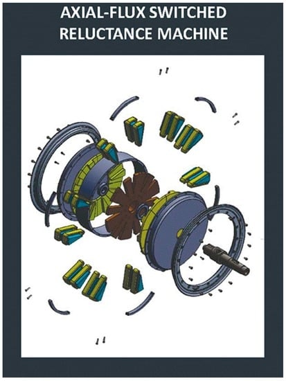
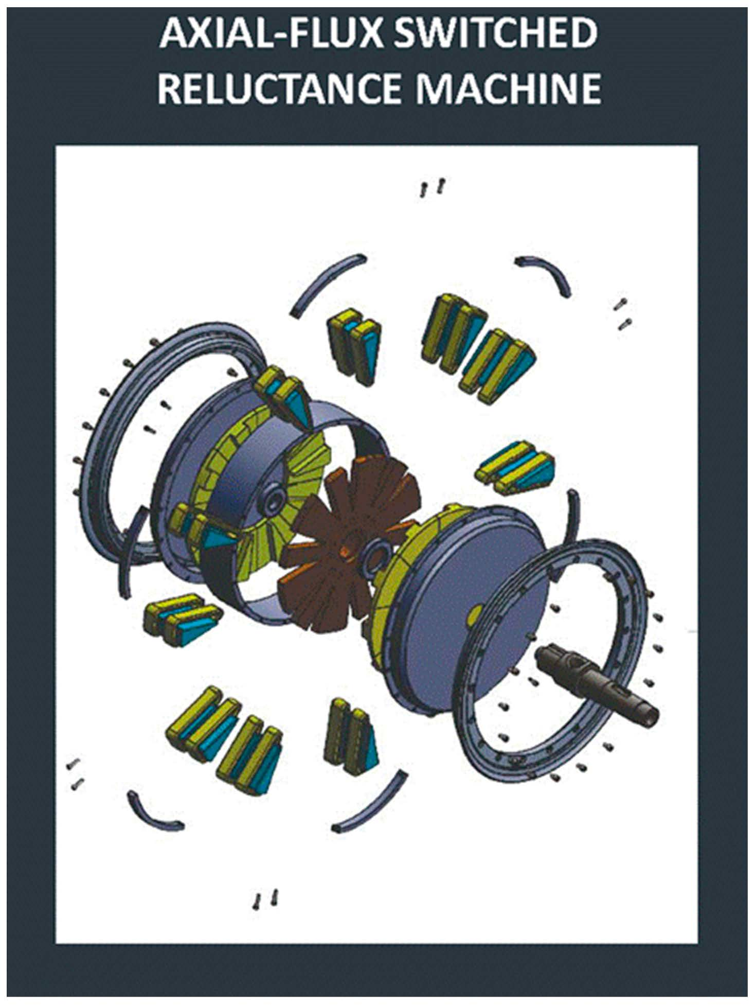
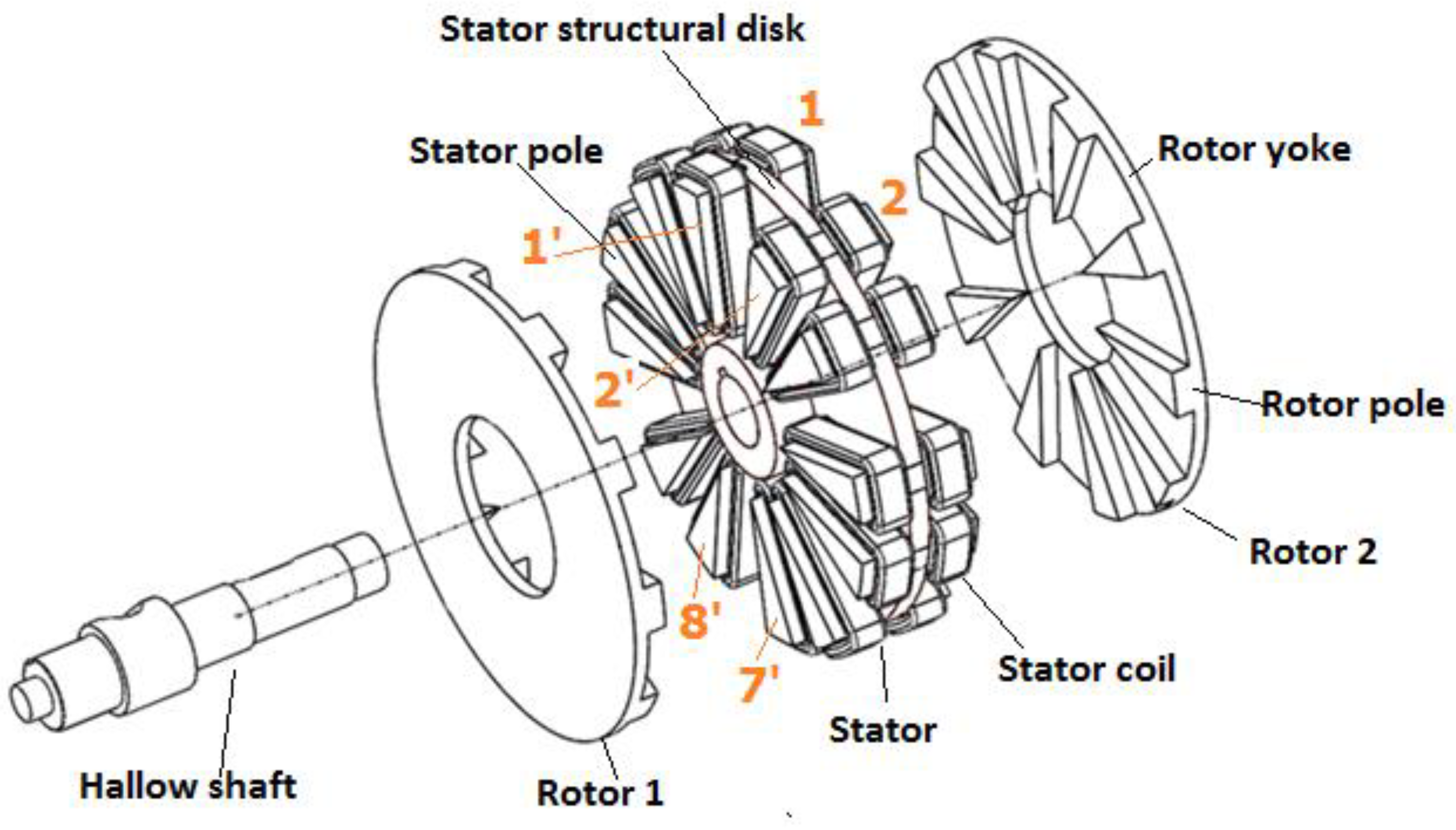
6]. The 10 ferromagnetic poles of each rotor were joined on the opposite side of the air gap, by means of an annular disk and rotor yoke, which were also made of ferromagnetic material. The stator consisted of 12 poles of a triangular shape also of ferromagnetic material, protruding at both ends and with the same sized structural disk nailed to a hollow shaft. The poles were made of ferromagnetic material and the structural disk of nonmagnetic material. A diagram of such a motor is shown in
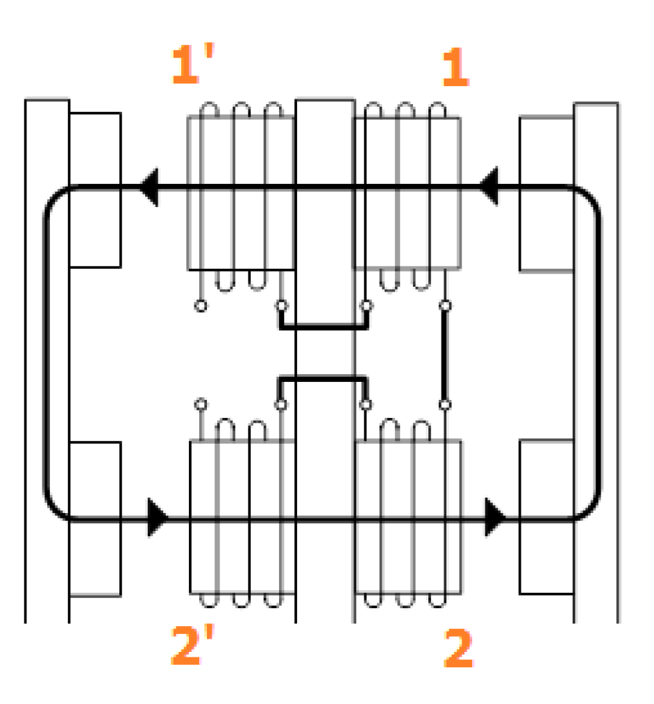
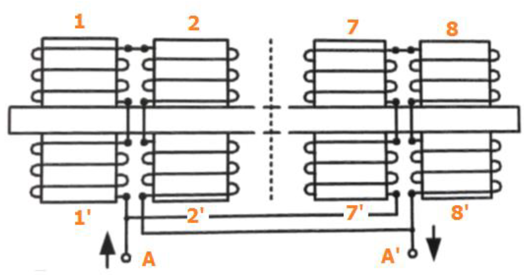
Figure 1. Two coils were wound in the opposite ends of the stator poles and connected in series. A group of two stator poles, with their corresponding coils connected in such a way that resulted in a single flux loop closed through two rotors poles, is called a double electromagnet, as shown in
Figure 2. As the described machine had six double electromagnets, the phase windings were obtained by connecting these in a proper way; in this case, in parallel (see
Figure 3), with the two double electromagnets of each phase. In any case, the terminals of the phase windings were led out of the machine through the hollow shaft.
The magnetic circuit of the motor consisting of stator poles and rotor poles was built using soft magnetic composites (SMCs) [
7,
8,
9], because these materials allow the construction of three-dimensional magnetic circuits of electric machines, which would be very difficult or very expensive to manufacture with laminated soft magnetic materials [
10,
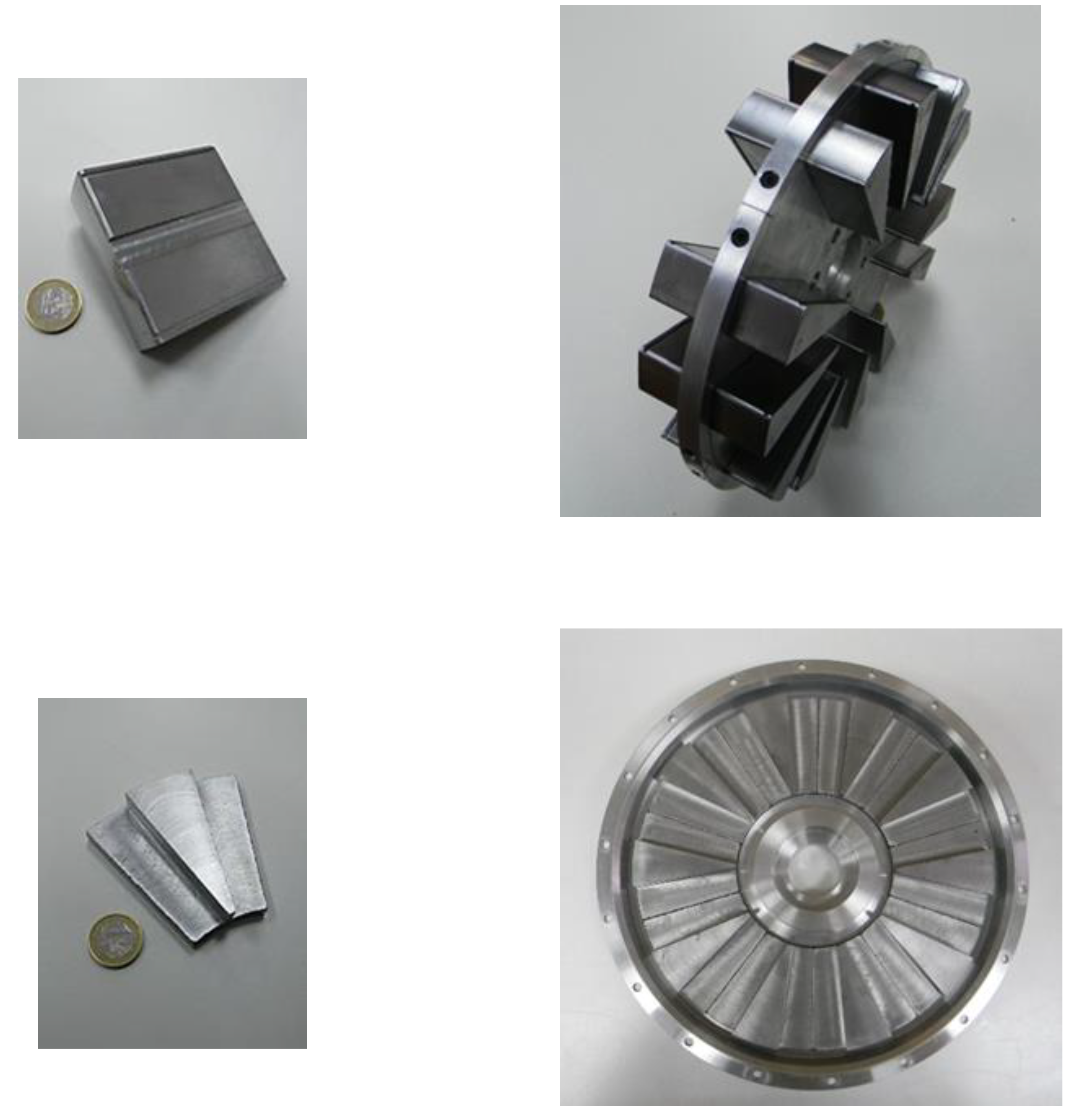
11]. It is important to point out that both rotors, for constructional reasons, could not be made in one piece and had to be built with several parts, one for each pole.
Figure 4 shows, in the upper left image, one stator pole piece and, in the upper right image, all the stator poles inserted in the structural disk of the aluminum. In the lower left image, one rotor pole piece is shown, and in the lower right image, all the rotor pole pieces of one rotor glued in the cover are shown.
Figure 4 clearly shows the modularity of the proposed AFSRM. In the
Appendix, the main dimensions and the bill of the materials of the proposed AFSRM are reported.
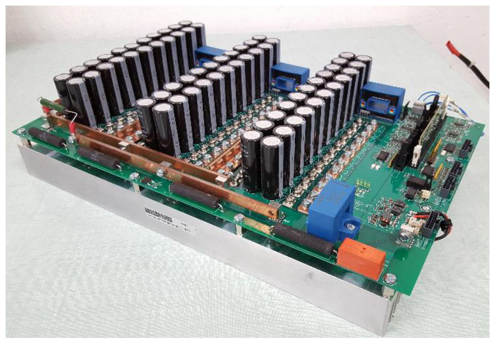
The AFSRM was designed for the propulsion, direct drive, of a light electric scooter with the following requirements: 90 Nm at 424 rpm and constant power 4 kW between 424 rpm and 1200 rpm. Before building the motor exhaustive simulations, the electromagnetic and thermal behavior of the motor and the whole drive, including the electronic power converter and control strategies, were carried out, and the simulations confirmed the previous requirements and specifications of the drive. Once the motor was built and tested, it was controlled using the SRM controller, as shown in
Figure 5 [
12].
Tests were performed according to the standard IEC 60349-Part 1 [
13] considering a guaranteed rating of a short time (1 h). The AFSRM was rated 4 kW at 900 rpm, 96 V of nominal voltage, and insulation class of 180 K. Temperature rise tests gave values in the stator windings higher than 180 K. Therefore, the AFSRM had to be derated at 2.8 kW (70% of the formerly rated value) with the same assigned values of the voltage and speed, giving, in these conditions, a temperature rise of 178 K under 180 K. These results were unexpected and very disappointing, so the causes of these differences were thus analyzed.
3. Methodology
In order to find out the causes of the discrepancies between the simulated and experimental results, the following methodology was adopted. First, the conditions under which the simulation was conducted were reviewed, and then the state of insulation was checked. The following step verified all the geometrical dimensions and finally, the quality of soft magnetic materials was studied.
3.1. Simulation
The simulation of the AFSRM drive, taking into account the electronic power converter, control, and AFSRM, was performed using Matlab-Simulink coupled with finite element analysis. However, for the purpose of this research, only electromagnetic analysis of the AFSRM was relevant, which was performed using a 3D flux package [
14], with the geometry of the AFSRM given in the
Appendix, considering both rotors made of only one piece of SMC with the magnetic properties of Somaloy 700 3P [
15].
3.2. State of Insulation
The state of insulation in electric machines should be periodically checked not only to prevent insulation failures but because the health of the insulation has an impact on the efficiency of the machine. Insulation resistance (IR) and polarization index (PI) tests are indicated as easily verifying the state of insulation. These tests were carried out in the AFSRM prototype, thus confirming the good state of its insulation.
3.3. Verification of the Geometrical Dimensions
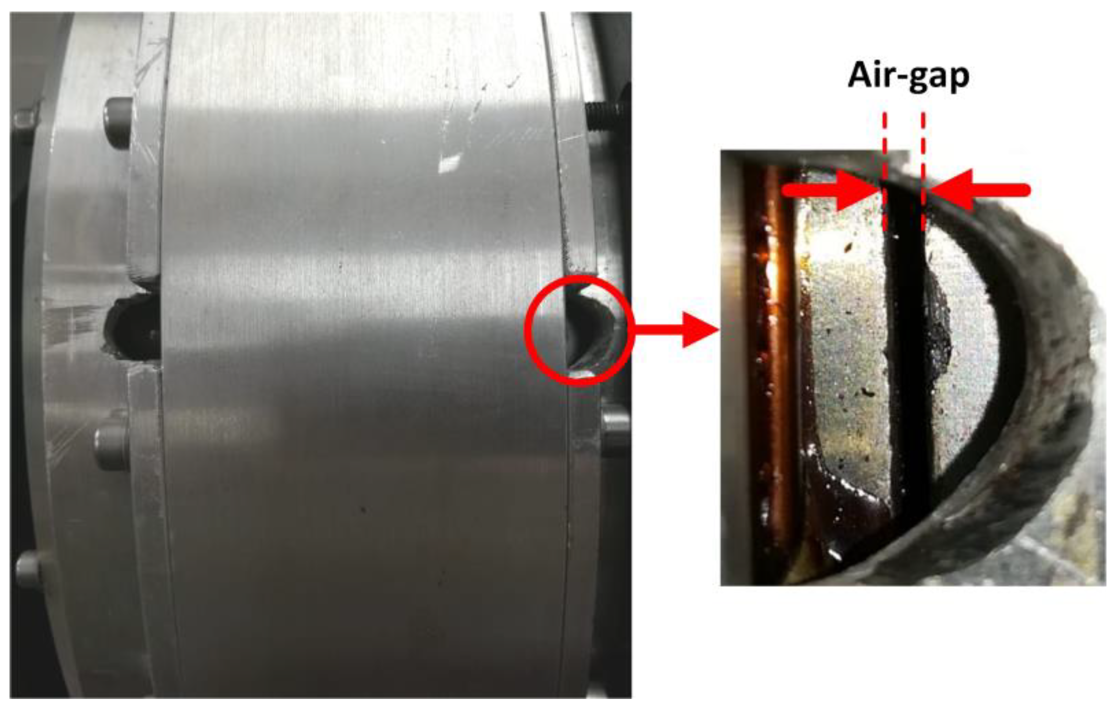
It is important to note that the proposed AFSRM has a greater constructive complexity than conventional radial-flux machines, especially due to the presence of the double air gap. All the geometrical dimensions of the AFSRM were verified, most of which were within the predicted tolerances; however, two important exceptions were detected. First, due to each rotor of the AFSRM being manufactured by 10 independent rotor pole pieces, it was observed that between two adjacent rotor pole pieces there was a parasitic air gap with an average length of 0.1 mm. Second, the air gaps between the stator and rotor were measured, making small windows in the housing that allowed the introduction of feeler gauges, as shown in
Figure 6, giving an average air gap of 0.6 mm, which is greater the designed gap of 0.5 mm. Special attention was paid to verify the average air gap between the stator and rotor poles on both sides of the machine, obtaining practically the same value on one side and on the other. If differences were found, it would imply the appearance of inconvenient axial forces in the machine. In addition, the correct alignment of the poles of both rotors was checked.
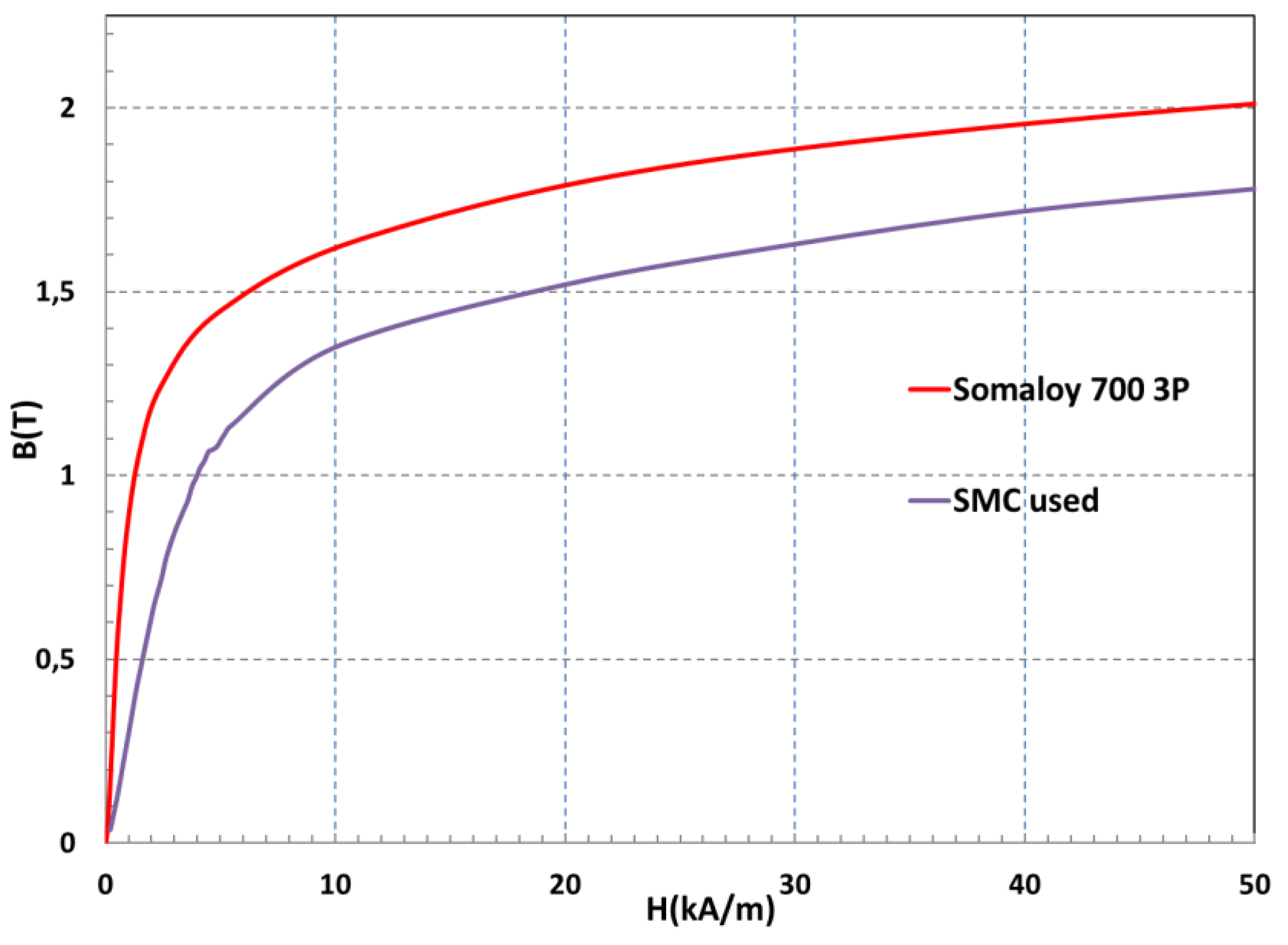
3.4. Study of the Quality of the Materials
Manufacturing of SMC pieces consists in mixing iron powder with a binder, then compacting it at high pressures (500–800 MPa) in a mold, with the shape of the piece, and curing it at relatively low temperatures of 200 to 650 °C. The magnetization curve and specific iron losses of the SMC are conditioned by the compacting process and thus the piece’s density [
7,
8,
9]. Most manufacturers of SMC provide a specific material for prototyping, which are machined blanks that suffer little change from subsequent machining processes. The stator and rotor pole pieces of the AFSRM were made by machining prefabricated blanks of an SMC that were expected to have the same magnetic properties, magnetization curve, and specific iron losses as the Somaloy 700 3P. The first thing that was done to evaluate the quality of the material used was to measure its density. The value obtained was 7.33 g/cm
3, significantly lower than the density of Somaloy 700 3P, which is 7.57 g/cm
3. This fact is an indicator that the magnetic properties of the SMC used in the construction of the AFSRM were worse than expected. Then, a ring of SMC was made with one of the polar pieces of the rotor to determine the magnetization curve, B-H curve, of the SMC used.
Figure 7 shows this curve and compares it with that of the Somaloy 700 3P.
After this study, it is clear that in the simulation, the modular construction of the rotors was not considered, obviating the existence of parasitic air gaps. The air gap between the stator and rotor poles due to assembly defects was larger than that considered in the simulation and the SMC used had worse magnetic properties than the Somaloy 700 3P.
4. Assessment of the Different Causes
Once the causes of the discrepancies between the simulation and the experimental results were identified, a magnitude was needed that allows quantitative assessment of the impact of the different causes. This magnitude should be inherent to the machine and not be conditioned for the control and it should be sensitive to the quality of the materials used and to changes in geometric dimensions. In addition, it should be easy to compute, and its experimental determination should be uncomplicated. The magnitude that verifies these conditions is the static torque, and for the purpose of this investigation, static torque curves, torque versus position for different values of the current with rotor blocked at different positions, were very useful. In all cases, the static torque curves were obtained by 3D finite element analysis using the 3D Flux package.
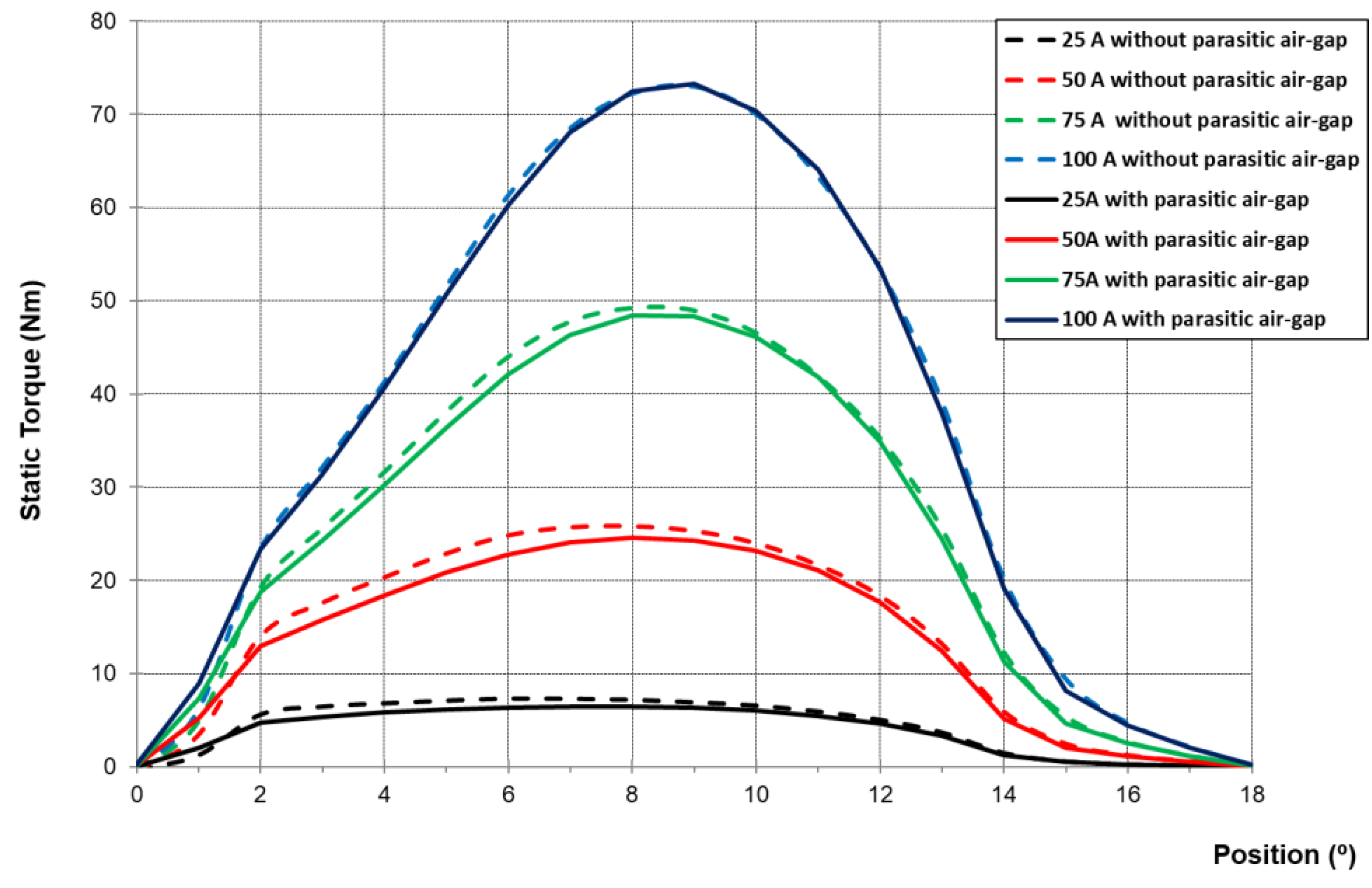
4.1. Evaluation of the Impact of Parasitic Air Gaps
Static torque curves (
Figure 8) were determined by taking into account the modular construction of both rotors of the AFSRM with a parasitic air gap of 0.1 mm between adjacent rotor pole pieces.
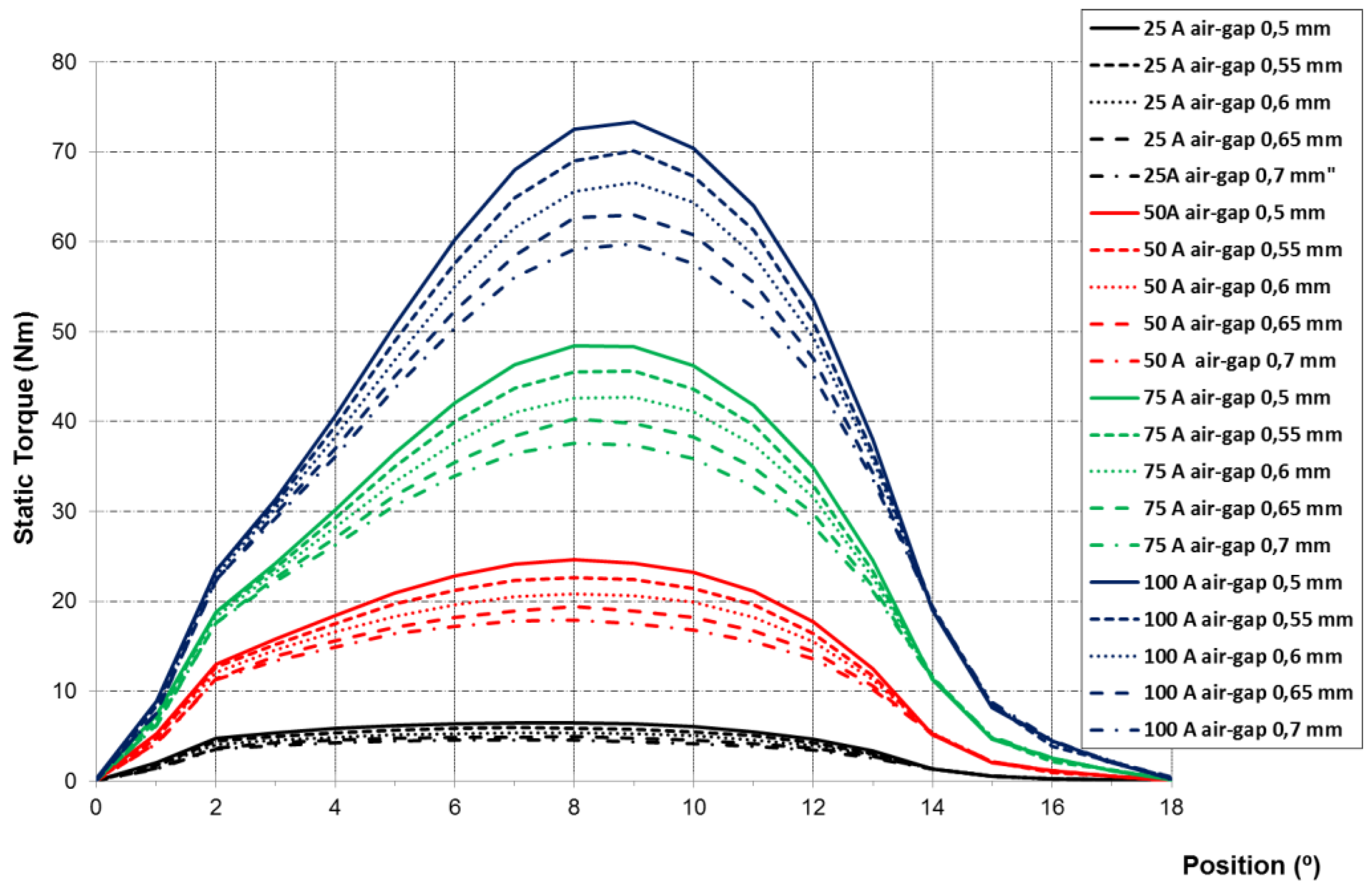
4.2. Evaluation of the Impact of Air Gap between the Stator and Rotor Poles
Static torque curves (
Figure 9) were determined considering different values of the air gap length between the stator and rotor poles due to assembly defects.
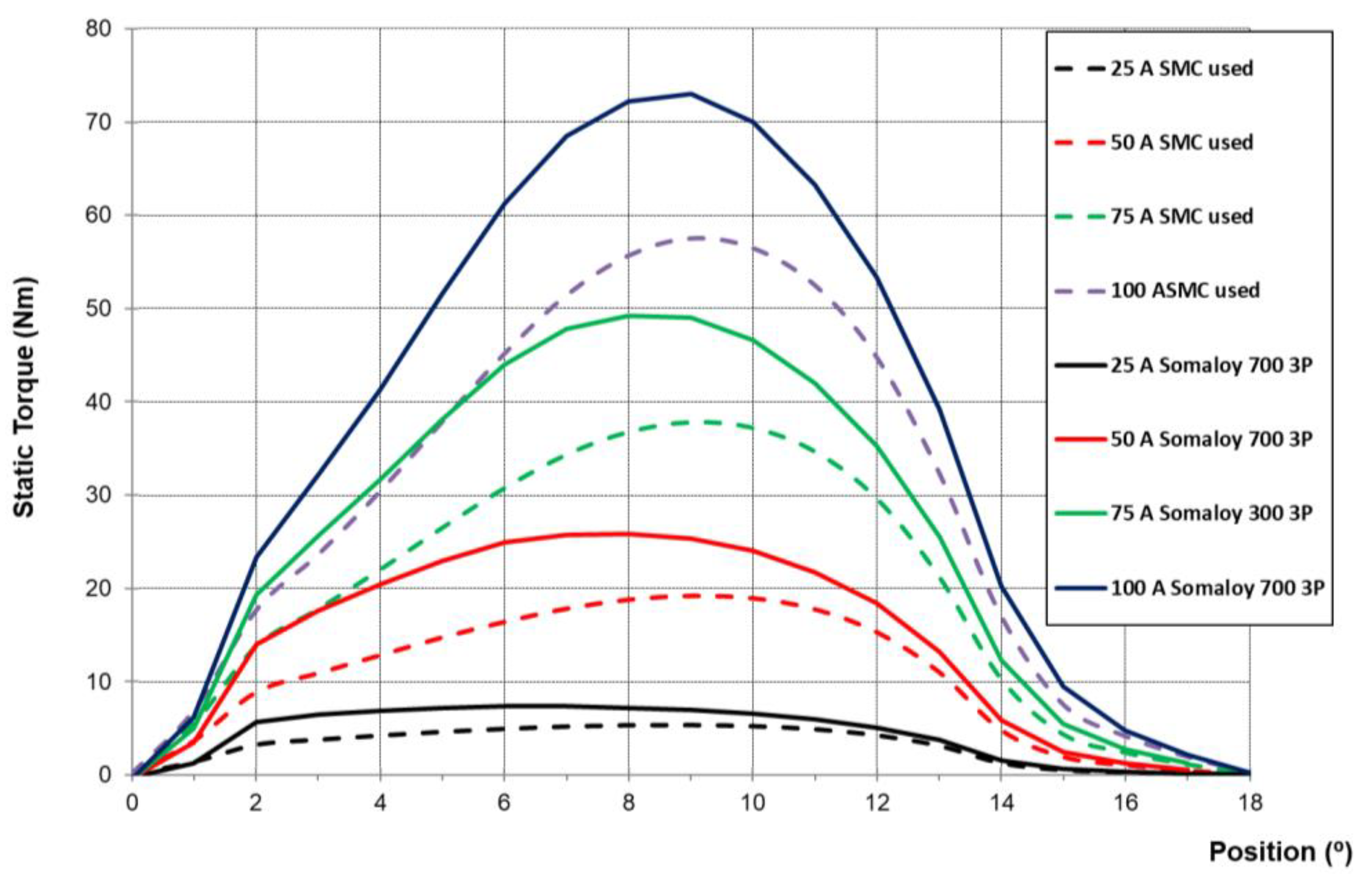
4.3. Evaluation of the Impact of the Quality of Materials
Static torque curves regarding the SMC used were determined and compared with those obtained with Somaloy 700 3P, as shown in
Figure 10.
This study demonstrates that the modular construction, which inevitably involves the existence of parasitic air gaps, has little impact on the static torque. Conversely, small variations in the air gap between the stator and the rotor, due to assembly defects, have an important influence on the static torque, an effect that is more acute with higher values of current. Likewise, the use of SMC with worse magnetic properties leads to a significant reduction of the static torque.
5. Experimental Determination of Static Torque
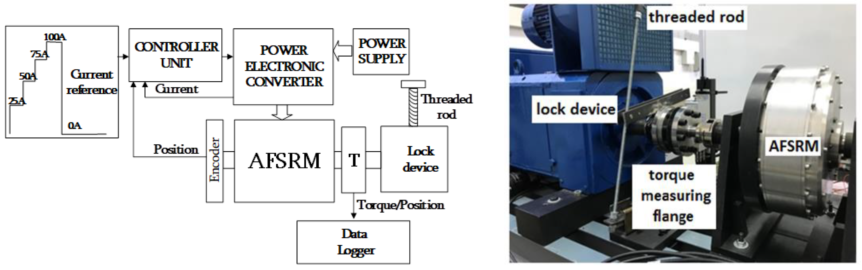
The static torque curves were obtained experimentally by means of the setup shown in
Figure 11. It consisted of a device that locked the AFSRM to a torque-measuring flange (KISTLER 4550A500S10N1KA 500 Nm), T, while a phase of the machine was excited with direct current through the power electronic converter that usually controls de AFSRM, as shown in
Figure 5. The position from the complete alignment of the stator and rotor poles to that of its complete misalignment was adjusted manually by means of a threaded rod setting, the reference of position at each moment. In order to ensure proper operation of the setup, a controller unit was needed, which generate the correct control signals of the electronic power converter for given current and position references and known actual current and position values. The values of torque, current, and position were recorded by a data logger (HBM eDrive GEN2 system 6 ch-2 mS/s with an embedded computer). The accuracy of the measurements was compromised by the torque meter precision (Class 0.25 when the torque meter is rated at 100 Nm) and by the thread pitch of the threaded rod (5 turns 1°).
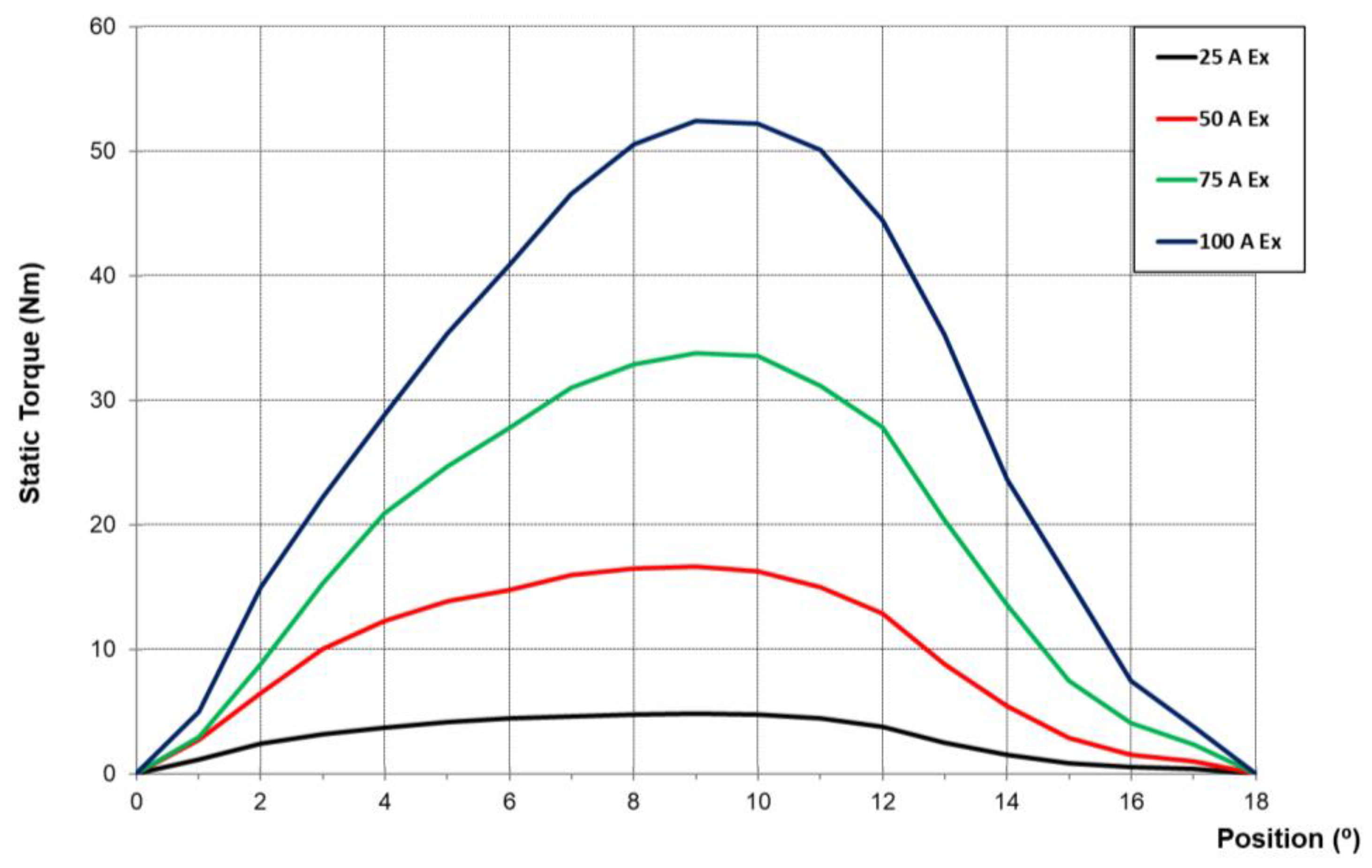
Figure 12 shows the experimental static torque curves for different currents obtained with the mentioned setup.
6. Discussion
Once the impact of the different causes responsible for the discrepancies between the simulation and experimental results were seen in
Figure 8,
Figure 9 and
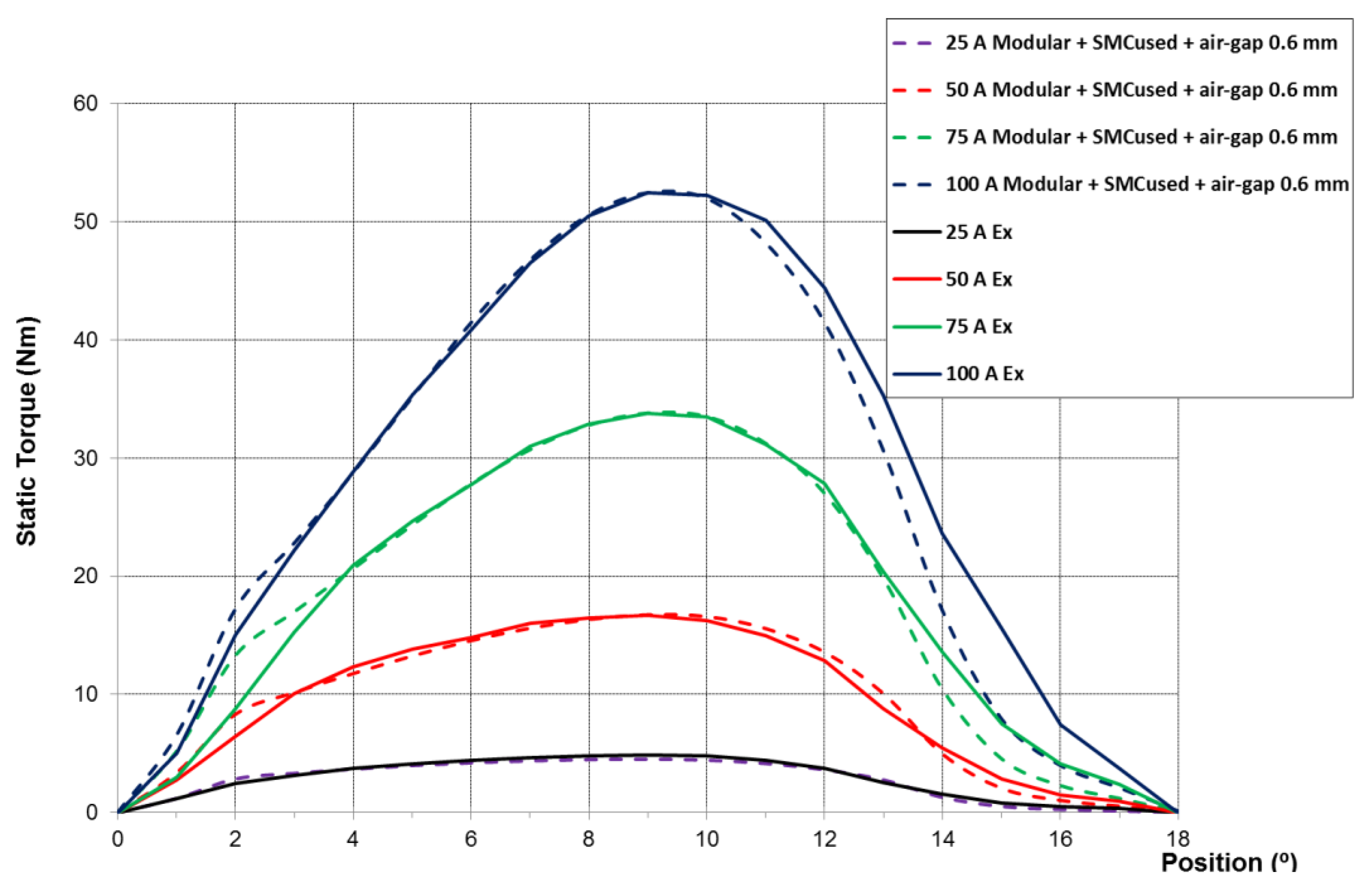
Figure 10, the static torque curves considering the combined effects of a 0.1-mm parasitic air gap between adjacent rotor pieces, an average air gap between the stator and rotor of 0.6 mm, and the actual magnetic properties of the SMC used were determined and compared with those obtained experimentally. This comparison is shown in
Figure 13, where it can be seen that both curves match pretty well except near the extreme positions (0° and 18°). This deviation can be attributed to a slight mismatch of the zero-position adjustment in the experimental setup. That confirms that manufacturing decisions, modular construction of the rotors, assembly defects, higher air gap than the designed gap, and bad quality SMC are the causes of the discrepancies between the simulated and experimental values. Therefore, from this research, the influence of manufacturing and assembly defects and the quality of materials on the performance of the considered AFSRM was clearly proven.
From this research, the following recommendations for the better design and construction of AFSRMs can be given:
The design must be done by checking all the dimensions of the different components, which must be specified with high precision tolerances, as well as the machining operations used to ease the assembly of the machine.
SMC parts, regardless of the way they are constructed, should be designed with tight tolerances to avoid mismatches and minimize parasitic air gaps.
In order to guarantee the quality of the SMC, the density of the pieces built with these materials should be checked before assembly. In the case that the resulting values are lower than those assigned by the SMC supplier, this is indicative of worse magnetic properties and the pieces should be rejected.
In the assembly, it must be ensured that the air gaps between the stator and both rotors are the same as those preset in the design. It is also necessary to check the correct alignment of the poles of both rotors; nevertheless, a slight shift between them may contribute to reducing, to some extent, torque ripple, although this statement requires further research.
7. Conclusions
In this paper, the influence of manufacturing and assembly defects and the quality of materials on the performance of an AFSRM was investigated. An AFSRM drive was designed and built for the in-wheel propulsion of an electric scooter. The proposed AFSRM had a double rotor and a particular disposition of the stator and rotor poles with short flux paths and without flux reversal. It was modular and its magnetic circuit was made using SMC. The motor was tested according to IEC 60349-Part 1, but the experimental results were below those expected and obtained by simulations. The causes of this discrepancy were first analyzed and then assessed using static torque curves. After an exhaustive study, it could be stated that modular construction of rotors, introducing parasitic air gaps, assembly deficiencies, higher air gap between the stator and rotor, and poor quality SMC were the main causes of the mentioned discrepancies. From this investigation, it can be concluded that larger air gaps between the stator and rotor due to assembly defects, the use of magnetic materials with worse B-H curves than expected, and, to a lesser extent, the modular construction of the rotor introduce unavoidable parasitic air gaps, which have a harmful influence on the torque and power output of an AFSRM drive. In addition, from this research, recommendations for better design and construction of AFSRMs can be drawn.
Author Contributions
Conceptualization, P.A.; Methodology, P.A.; Simulation, E.M.; Mounting, B.B. and J.A.S.; Tests, B.B., J.I.P. and M.T.; Writing—original draft preparation, P.A. and M.T.; Writing—review and editing, P.A., B.B., E.M., J.I.P., J.A.S. and M.T.
Funding
This research was supported by Spanish Ministry of Economy and Competitiveness (DPI 2014-57086-R and FEDER Funds).
Acknowledgments
Authors would like to thank AMES S.A. for providing the SMC pieces and specially Dr. Mark Dougan Chief Metallurgist, Dept. of R&D AMES S.A. and Dr. José Antonio Calero R&D Manager of AMES S.A. for their support.
Patent
PCT/EP2017/076976, “An axial flux switched reluctance machine and an electric vehicle comprising the machine”.
Conflicts of Interest
Authors declare no conflict of interest.
Main Dimensions of the AFSRM Proto
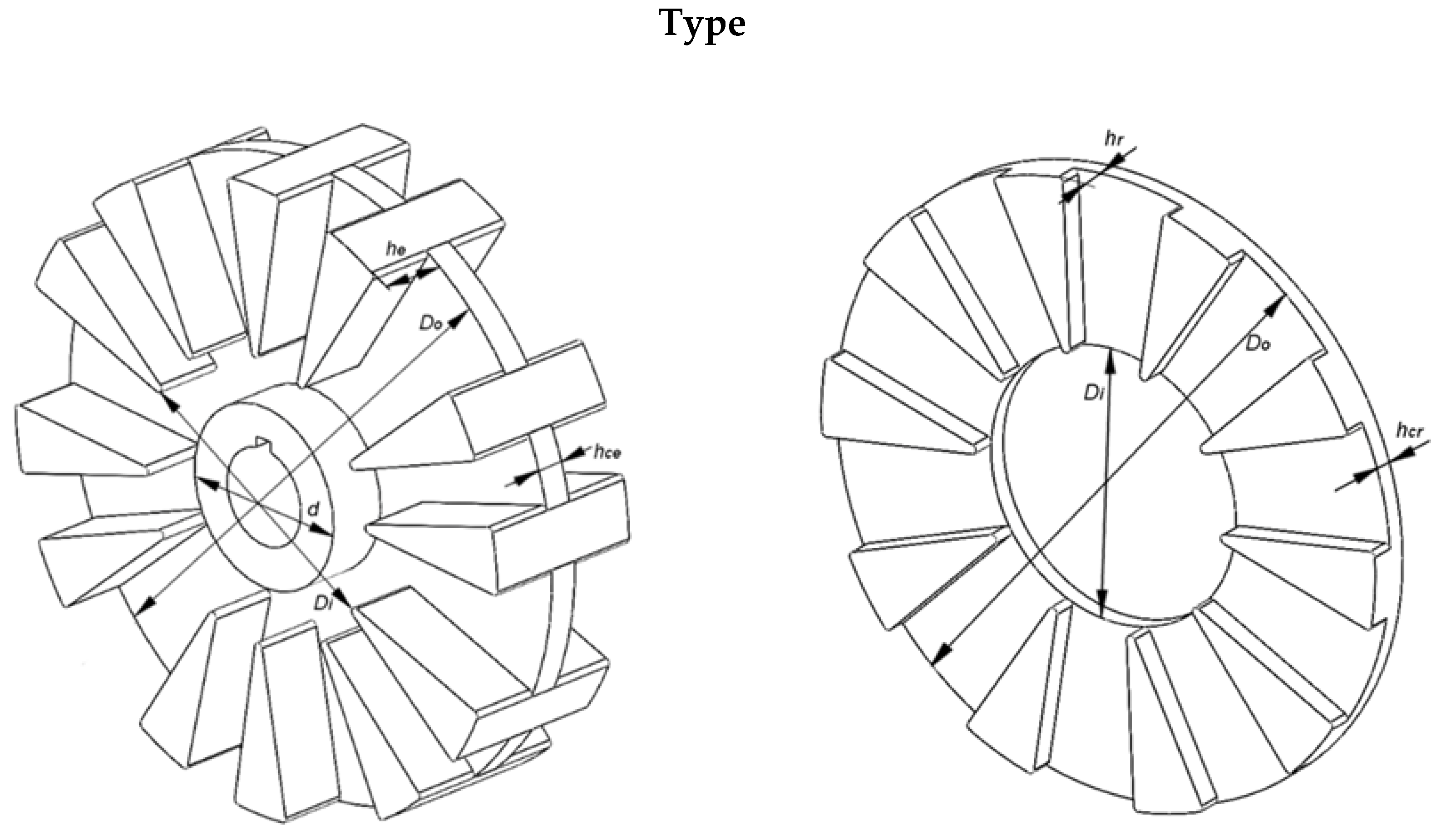
Figure A1.
Stator and rotor main dimensions.
Figure A1.
Stator and rotor main dimensions.
Table A1.
Main dimensions of the AFSRM prototype.
Table A1.
Main dimensions of the AFSRM prototype.
| Parameter | Symbol | Values |
|---|
| Number of phases | m | 3 |
| Number of double electromagnets | Z | 6 |
| Number of stator poles | NS | 12 |
| Number of rotor poles | NR | 10 |
| Angle between rotor poles | α | 36 |
| Angle between axes of stator poles of the two consecutive double electromagnets | δ | 24 |
| Angle between axes of consecutive double electromagnets | γ | 60 |
| Output stator/rotor diameter | Do | 260 mm |
| Inner rotor diameter | Di | 117.9 mm |
| Inner stator diameter | d | 50 mm |
| Air gap | g | 0.5 mm |
| Height of protruding stator pole | he | 28.9 mm |
| Thickness of supporting disk | hce | 12 mm |
| Height of rotor pole | hr | 10 mm |
| Thickness of rotor yoke | hcr | 8 mm |
Table A2.
Bill of materials.
Table A2.
Bill of materials.
| Parts | Material |
|---|
| Rotor poles | SMC used |
| Stator poles | SMC used |
| Rotor covers | Aluminum AW6060 (EN 573-3) |
| Rotor housing | Aluminum AW6060 (EN 573-3) |
| Shaft | Steel C45 E (EN 10277-5) |
References
- Jahns, T. Getting rare-earth magnets out of EV traction machines: A review of the many approaches being pursued to minimize or eliminate rare earth magnets from future EV drive trains. IEEE Electrif. Mag. 2017, 5, 6–18. [Google Scholar] [CrossRef]
- Torkaman, H.; Ghaheri, A.; Keyhani, A. Axial flux switched reluctance Machines: A comprehensive review of design an topologies. IET Electr. Power Appl. 2019, 13, 210–321. [Google Scholar] [CrossRef]
- Andrada, P.; Dougan, M.J.; Egea, A.; Márquez-Fernández, M.J.; Szabó, L. Are SRM drives a real alternative for EV powertrain? In Proceedings of the Workshop on SRM an Alternative for E-traction, Vilanova i la Geltrú, Barcelona, Spain, 2 February 2018.
- Andrada, P.; Martínez, E.; Blanqué, B.; Torrent, M.; Perat, J.I.; Sánchez, J.A. New axial-flux switched reluctance motor for E-scooter. In Proceedings of the ESARS ITEC, Toulouse, France, 2–4 November 2016. [Google Scholar]
- Andrada, P.; Martínez, E.; Torrent, M.; Blanqué, B. Electromagnetic evaluation of an in-wheel double rotor axial-flux switched reluctance motor for electric traction. Renew. Energy Power Qual. J. 2017, 15, 671–675. [Google Scholar] [CrossRef] [Green Version]
- Andrada, P.; Blanqué, B.; Martínez, E.; Sánchez, J.A.; Torrent, M. In wheel-axial-flux SRM drive for light electric vehicles. In Proceedings of the Workshop on SRM an Alternative for E-traction, Vilanova i la Geltrú, Barcelona, Spain, 2 February 2018. [Google Scholar]
- Anderson, O.; Hofecker, P. Advances in Soft Magnetic Composites-Materials and Applications. In Proceedings of the International Conference on Powder Metallurgy & Particulate Materials, Las Vegas, NV, USA, 28 June–1 July 2009. [Google Scholar]
- Schoppa, A.; Delarbre, P. Soft magnetic powder composites and potential applications in modern electric machines and devices. IEEE Trans. Magn. 2014, 50. [Google Scholar] [CrossRef]
- Krings, A.; Boglietti, A.; Cavagnino, A.; Sprague, S. Soft magnetic material status and trends in electrical machines. IEEE Trans. Ind. Electron. 2017, 64, 2405–2414. [Google Scholar] [CrossRef]
- Liu, C.; Lu, J.; Wang, Y.; Lei, G.; Zhu, J.; Guo, Y. Design Issues for Claw Pole Machines with Soft Magnetic Composite Cores. Energies 2018, 11, 1998. [Google Scholar] [CrossRef] [Green Version]
- Zhang, B.; Seidler, T.; Dierken, R.; Doppelbauer, M. Development of a yokeless and segmented armature axial flux machine. IEEE Trans. Ind. Electron. 2016, 63, 2062–2071. [Google Scholar] [CrossRef]
- Andrada, P.; Blanqué, B.; Capó, M.; Gross, G.; Montesinos, D. Switched Reluctance Motor Controller for Light Electric Vehicles. In Proceedings of the 20th European Conference on Power Electronics and Applications, EPE’18 ECCE Europe, Riga, Latvia, 17–21 September 2018; pp. P1–P11. [Google Scholar]
- Rotating Electrical Machines for Rail and Road Vehicles. Different from a.c. Motors Powered by Electronic Converter, International Standard IEC, 60349, Part 1; IEC: Geneva, Switzerland, October 2011. [Google Scholar]
- Flux 12.1; Altair: Troy, MI, USA, 2019.
- Höganas. Somaloy® 3P Material Data. Available online: https://www.hoganas.com/globalassets/download-media/sharepoint/brochures-and-datasheets—all-documents/somaloy-3p_material-data_june_2018_2273hog.pdf (accessed on 3 December 2019).
© 2019 by the authors. Licensee MDPI, Basel, Switzerland. This article is an open access article distributed under the terms and conditions of the Creative Commons Attribution (CC BY) license (http://creativecommons.org/licenses/by/4.0/).


