Article

Simulation Study to Investigate the Effects of Operational Conditions on Methylcyclohexane Dehydrogenation for Hydrogen Production

1
Department of Chemical Engineering, COMSATS University Islamabad, Lahore Campus, Defence Road, Off-Raiwind Road, Lahore 54000, Pakistan
2
Department of Chemical Engineering, College of Engineering, Jazan University, Jazan 45142, Saudi Arabia
3
Institute of Chemical Engineering and Technology, University of the Punjab, New Campus, Lahore 54590, Pakistan
*
Authors to whom correspondence should be addressed.
Submission received: 29 November 2019 / Revised: 27 December 2019 / Accepted: 30 December 2019 / Published: 1 January 2020

Abstract

:
In the recent era, hydrogen has gained immense consideration as a clean-energy carrier. Its storage is, however, still the main hurdle in the implementation of a hydrogen-based clean economy. Liquid organic hydrogen carriers (LOHCs) are a potential option for hydrogen storage in ambient conditions, and can contribute to the clean-fuel concept in the future. In the present work, a parametric and simulation study was carried out for the storage and release of hydrogen for the methylcyclohexane toluene system. In particular, the methylcyclohexane dehydrogenation reaction is investigated over six potential catalysts for the temperature range of 300–450 °C and a pressure range of 1–3 bar to select the best catalyst under optimum operating conditions. Moreover, the effects of hydrogen addition in the feed mixture, and byproduct yield, are also studied as functions of operating conditions. The best catalyst selected for the process is 1 wt. % Pt/γ-Al2O3. The optimum operating conditions selected for the dehydrogenation process are 360 °C and 1.8 bar. Hydrogen addition in the feed reduces the percentage of methylcyclohexane conversion but is required to enhance the catalyst’s stability. Aspen HYSYS v. 9.0 (AspenTech, Lahore, Pakistan) has been used to carry out the simulation study.

Graphical Abstract

1. Introduction

Conventional fuel-based power generation systems are the major contributors to air pollution in the modern era. Researchers all over the world are in the continuous effort to introduce environmentally friendly fuels not only to cope up with this issue but also to fulfill the future fuel demand. Over the years, various solutions have been projected to assuage ecological impairment and future fuel deficiency. Onboard hydrogen storage is one of those viable solutions which propose hydrogen usage as a fuel in proton-exchange membrane (PEM) fuel cells, hydrogen-fired gas turbines, or in internal combustion engines [1,2,3]. The hydrogen-based energy system has potential as a future fuel, as in comparison to other available fuels, hydrogen has maximum energy per unit mass, i.e., 119 kJ/gm at normal temperature and pressure (NTP), with no greenhouse gases as the product of combustion. The global environmental index for various fuels is presented in Table 1, which shows that hydrogen as a fuel is comparatively cleaner than various fossil fuels [4].
However, chemically, hydrogen is not available freely like other fossil fuels, so it is considered as the carrier of energy, not as a fuel [1,5]. The problems associated with the hydrogen system is its storage and transportation [1,2]. Various techniques are under investigation for the advancement of a cost-effective and safe system for the efficient storage of hydrogen, such as liquefaction, compression, absorption in a metal–organic framework, nanotubes, etc. Among others, liquid organic hydrogen carriers (LOHCs) are the compounds (mainly aromatics) that can be used to store and transport hydrogen (4–7 wt. %) via reversible reactions of hydrogenation and dehydrogenation. This concept provides a solution towards the implementation of a sustainable and efficient hydrogen-based economy, i.e., the solution to the transportation and storage problems of hydrogen [2,3,6]. A comparison of energy and cost assessments of various hydrogen-storage techniques is presented in Table 2 [3].
Energy consumption takes place during the processing, storage, and transportation of hydrogen, and must be considered in the calculations of the energetic efficiency of the system. The energy consumption can also be termed as energy loss/waste heat, which cannot be regained economically [3].
Among the various H2 storage techniques, three potential candidates, i.e., LOHC (MCH–toluene system), NH3, and Liquid H2 have been compared. The comparison has been presented in Table 3 [7].
The gravimetric density of liquid H2 is highest, followed by NH3 and LOHC. For the storage of hydrogen through NH3, MCH and Liquid H2, existing infrastructure along with established rules and regulations are developed. The regeneration temperatures required for the NH3 system are in the range of 400–500 °C, compared with 100–200 °C for the LOHC system. Therefore, LOHC has been termed as an efficient technique, as it is comparatively the most established and efficient technique [7].
Various systems exist under the umbrella of LOHC, the comparisons of which have been presented in Table 4 [7,8,9]. The comparison shows that despite the lower gravimetric and volumetric densities of the MCH–toluene system, this system has better applicability due to the following reasons, among others:
  • MCH and toluene exist in liquid form, and have no handling issues, unlike the naphthalene–decalin system, in which naphthalene exists in a solid state, thus causing handling issues, making this system unfavorable for operation.
  • Comparatively, benzene is more toxic than methylcyclohexane. As reported by US health exposure limits (NIOSH), the permissible exposure limit of benzene is 1 ppm and methylcyclohexane is 500 ppm. An exposure limit of 500 ppm of benzene causes immediate danger, while 1200 ppm of MCH does the same.
  • The dibenzyl toluene–perhydro–dibenzyl toluene (DBT–PBT) system has a higher energy requirement for the dehydrogenation process as compared to the methylcyclohexane–toluene–hydrogen (MTH) system, making this system unfavorable for operation [3,7,10,11,12,13].
An overall LOHC system comprises reversible cycle hydrogenation and dehydrogenation for storage and release of hydrogen respectively. Although hydrogenation is achieved with good efficiency (98% efficiency), still the dehydrogenation or unloading step is a major hurdle in this process [14].
Various researchers conducted the experimental work to investigate the methylcyclohexane dehydrogenation and byproducts formation rate using various catalysts. Taube et al. initially suggested technical parameters for the development of the MTH system for internal combustion engines [15]. Jothimurugesan et al., used 0.3 wt. % Pt-Re/Alumina catalyst. The Langmuir–Hinshelwood–Hougen–Watson (LHHW) model was found to be the best fit for the studied system. A 98.2% MCH conversion rate was achieved during the operation [16]. Mizsey et al., used a sulfided, reforming catalyst on a spherical alumina support, and achieved 98% MCH conversion on the pilot plant scale system [17]. Usman et al., used 0.3 wt. % Pt/Al2O3 catalyst based on the power law kinetic model, and reported 97.5% conversion of MCH conversion in the absence of hydrogen [18]. Usman et al., used 1 wt. % Pt/θ-Al2O3 catalyst, based on the power law and LHHW models and concluded that the LHHW model is the best fit for the system with this catalyst. Hydrogen addition in the feed promoted the dehydrogenation rate and reported a MCH conversion of 99.3% [19]. Usman et al., used 1 wt. % Pt/zeolite beta catalyst for both hydrogenation and dehydrogenation systems, and reported that % conversion of MCH was not clean, i.e., there was a high rate of byproduct formation. The authors reported MCH conversion of 83.32% for the dehydrogenation system, while 90.93 % conversion was reported for the hydrogenation system [20,21]. Usman et al., used 1 wt. % Pt/γ-Al2O3 catalyst, and reported a MCH conversion rate of 97% [22]. Usman et al. studied MCH dehydrogenation using a catalytic fixed-bed reactor to determine the selectivity and activity of the various catalysts. Percentage of MCH conversion using various catalysts is summarized in Table 5 [20]. Chen et al. designed and optimized the catalytic membrane reactor for MCH dehydrogenation to produce hydrogen [23]. Wang et al., carried out MCH dehydrogenation using Pt/Ce-Mg-Al-O catalyst, and achieved a MCH conversion rate of 98.5% [24]. Obara carried out energy and exergy analysis of a complete hydrogen energy supply chain using MCH and reported the total efficiency to be 18% with a heat to power ratio of 0.931 [25].
The literature survey shows that the MCH dehydrogenation process has been examined experimentally by various researchers. However, simulation aspects have not been covered appropriately, i.e., the present literature shows that kinetic data has not been studied and conversion reactors have been used to present the dehydrogenation system. The performance of the dehydrogenation system is mainly dependent on temperature and pressure conditions, and the percentage of conversion changes with changes in operational conditions and use of suitable catalysts [22,26,27]. The rate of reaction is dependent on the properties of the catalyst, i.e., activity, selectivity and stability. Percentage of conversion increases with the increase in selectivity of the catalyst. Both activity and selectivity of the catalyst are dependent on the nuclearity of the support material. However, there exists a trade-off between activity and selectivity, which is dependent on the nuclearity of support material [28,29]. The optimum value of temperature and pressure promotes the reaction rate, thus increasing the percentage of conversion of the system. However, for the catalytic system, the optimum values of temperature and pressure have a direct relationship with the catalyst deactivation [30,31,32].
The present study intends to address this research gap by investigating methylcyclohexane dehydrogenation for the hydrogen release and storage, based on a simulation–parametric study. The six catalysts are investigated for the dehydrogenation system to select the best catalyst for the process, under the optimum operational conditions, i.e., temperature, pressure, and hydrogen concentration at the reactor inlet. Aspen HYSYS v. 9.0 has been used to carry out the simulation study.

2. Simulation Study

Aspen HYSYS v. 9.0 was used to carry out the simulation of the overall system. The complete schematic of the system is presented in Figure 1, out of which the dehydrogenation system has been taken for this study. The remaining system has been studied previously [33].
Methylcyclohexane and hydrogen are fed to the dehydrogenation reactor. The purpose of the addition of hydrogen in the feed is to enhance the stability of the catalyst. The types of the catalysts used is presented in Table 6.
The overall process description is demonstrated in Figure 2.
The reactor model assumed in Aspen HYSYS v. 9.0 is Plug Flow. Peng–Robinson has been used as the thermodynamic property package. The process initiates with the feed pump, which is used to supply methylcyclohexane to the dehydrogenation reactor. Feed pre-heating takes place before pumping, through the following routes:
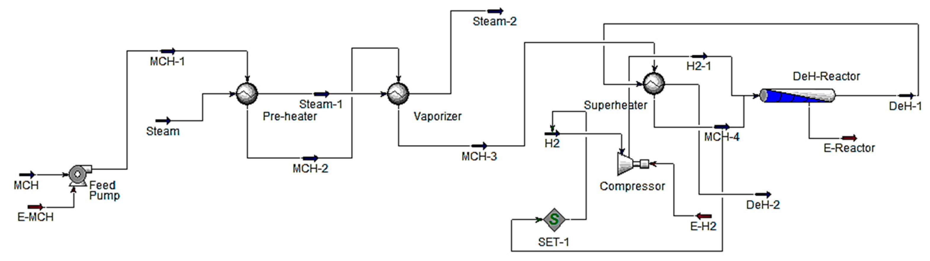
  • Pre-heater: heat is exchanged between methylcyclohexane (MCH-1) with saturated steam (Steam) from the exhaust of the extraction type steam turbine.
  • Vaporizer: the methylcyclohexane (MCH-2) exchanges heat with steam (Steam-1) in the vaporizer.
  • Superheater: the methylcyclohexane (MCH-3) exchanges heat with products of dehydrogenation reactor (DeH-1) to superheat the methylcyclohexane for the final pumping into the dehydrogenation reactor.
The methylcyclohexane (MCH-4) is fed to the dehydrogenation reactor (DeH-Reactor), where methylcyclohexane dehydrogenation to toluene and hydrogen is carried out using a suitable catalyst. The hydrogen addition is also done with the feed (after compression) to increase the catalyst stability and activity. Initially, the electrolysis section provides the hydrogen for the plant startup. Toluene and hydrogen production take place in the dehydrogenation reactor, which are separated using a separator. The separated hydrogen is fed/recycled to the dehydrogenation reactor (with methylcyclohexane) replacing hydrogen from the electrolysis section. The products of dehydrogenation reactor (DeH-1), after exchanging heat to methylcyclohexane (MCH-3) in the superheater (DeH-2), are sent to the separator for separation of hydrogen and other products. Part of the hydrogen is recycled, while part of the hydrogen is used to generate superheated steam (by reaction with oxygen in the steam generator). The superheated steam drives the steam turbine and the saturated steam (Steam) is used for pre-heating and vaporizing of the feed. The outlet steam (Steam-2) from the vaporizer is used in the different industrial processes.
The produced toluene is used for hydrogen storage in the hydrogenation reactor by reaction with hydrogen to yield methylcyclohexane. This reaction is highly exothermic and reaction heat is utilized to produce steam for power generation. The hydrogenation section is not considered in this study. The storage of the toluene is carried out at ambient temperature. Two main byproducts, i.e., cyclohexane and benzene, are considered in the study.
Operational conditions and catalysts are simultaneously varied in the simulation study to observe effect on the percentage of MCH conversion rate:
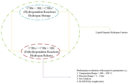
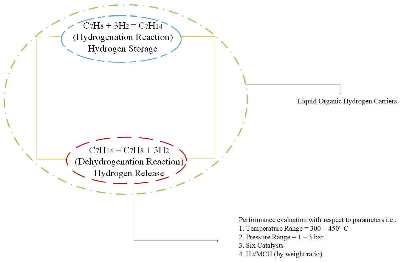
  • Pressure range: 1–3 bars.
  • Temperature range: 300–450 °C.
  • Concentration of hydrogen in the feed: H2/MCH ratio (by weight) at a value of 0 and 0.5.
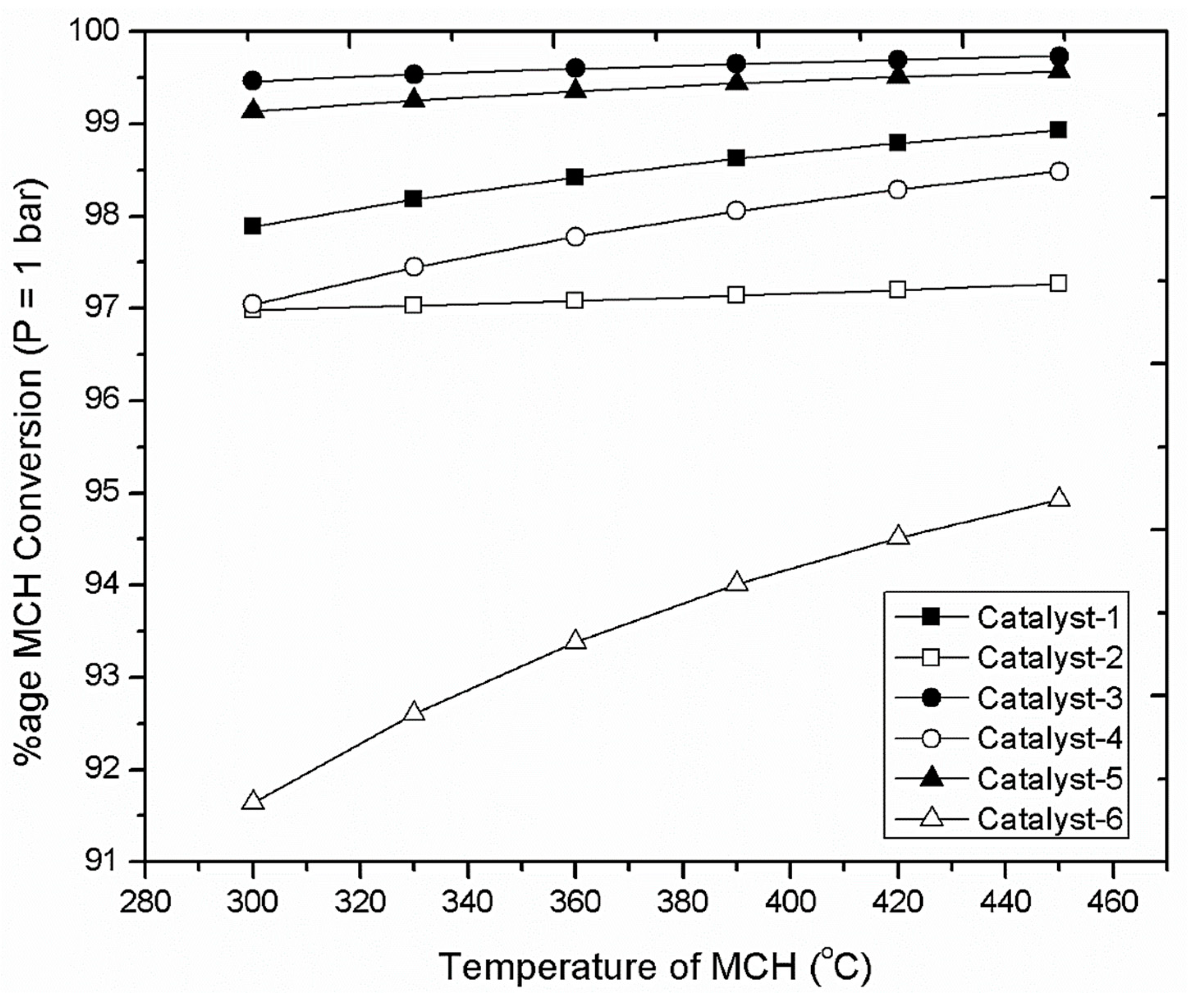
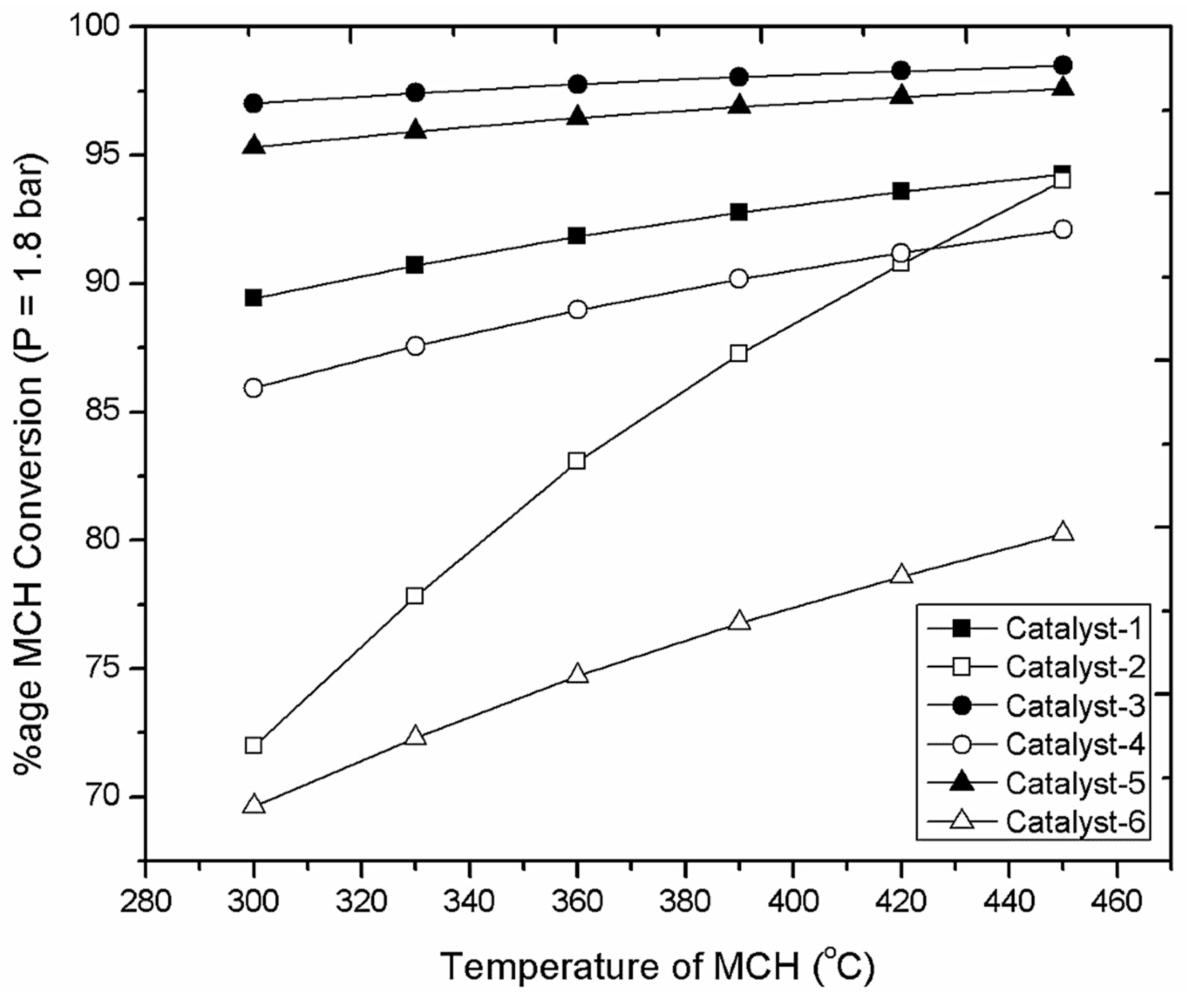
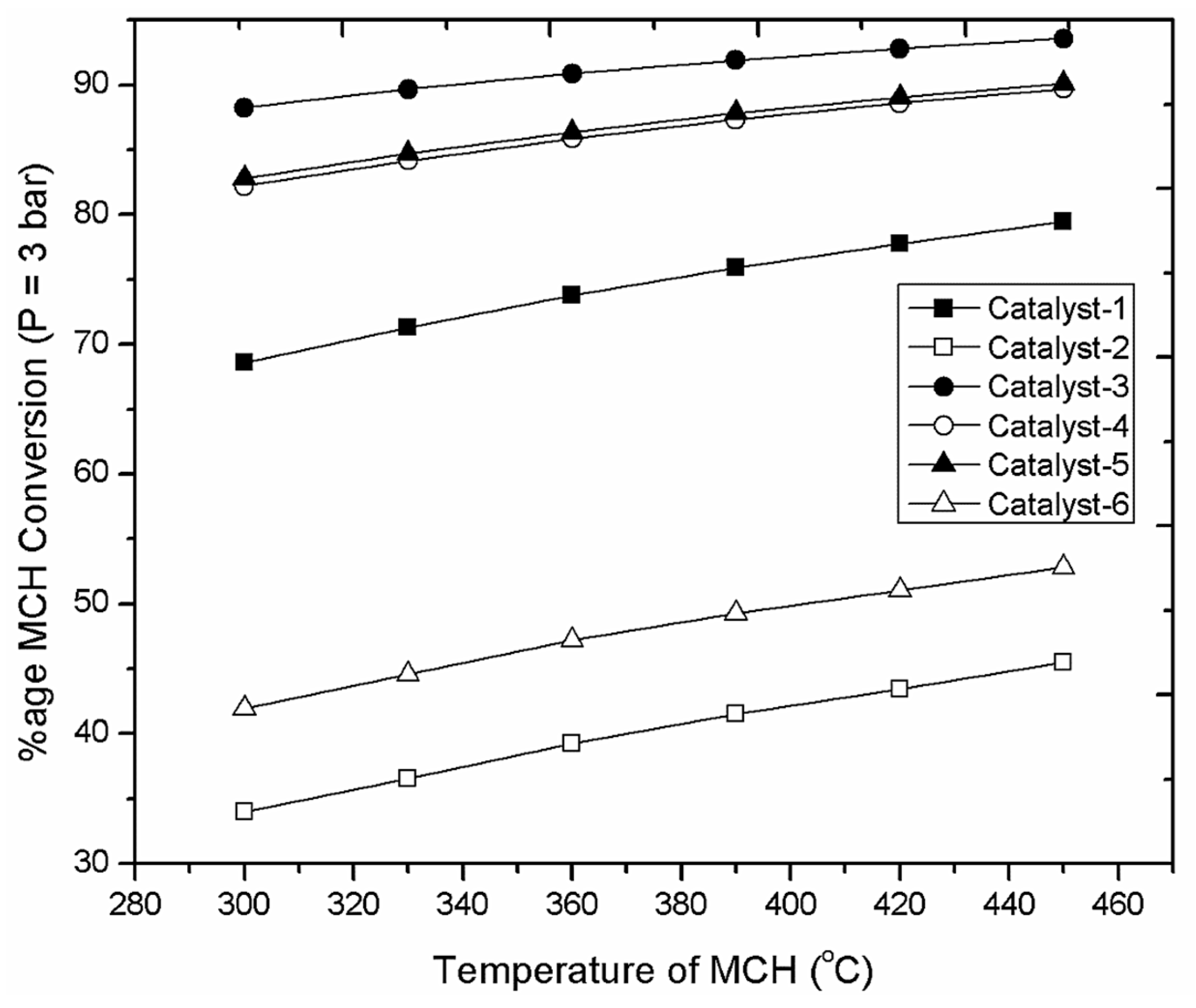
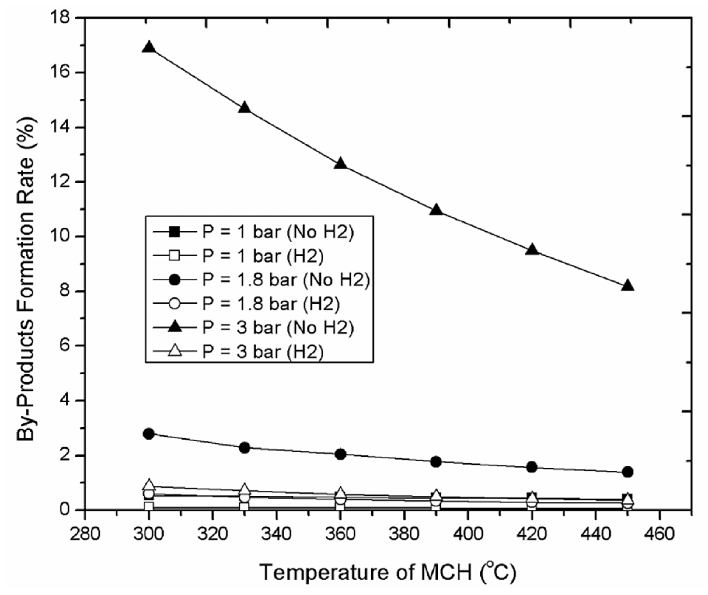
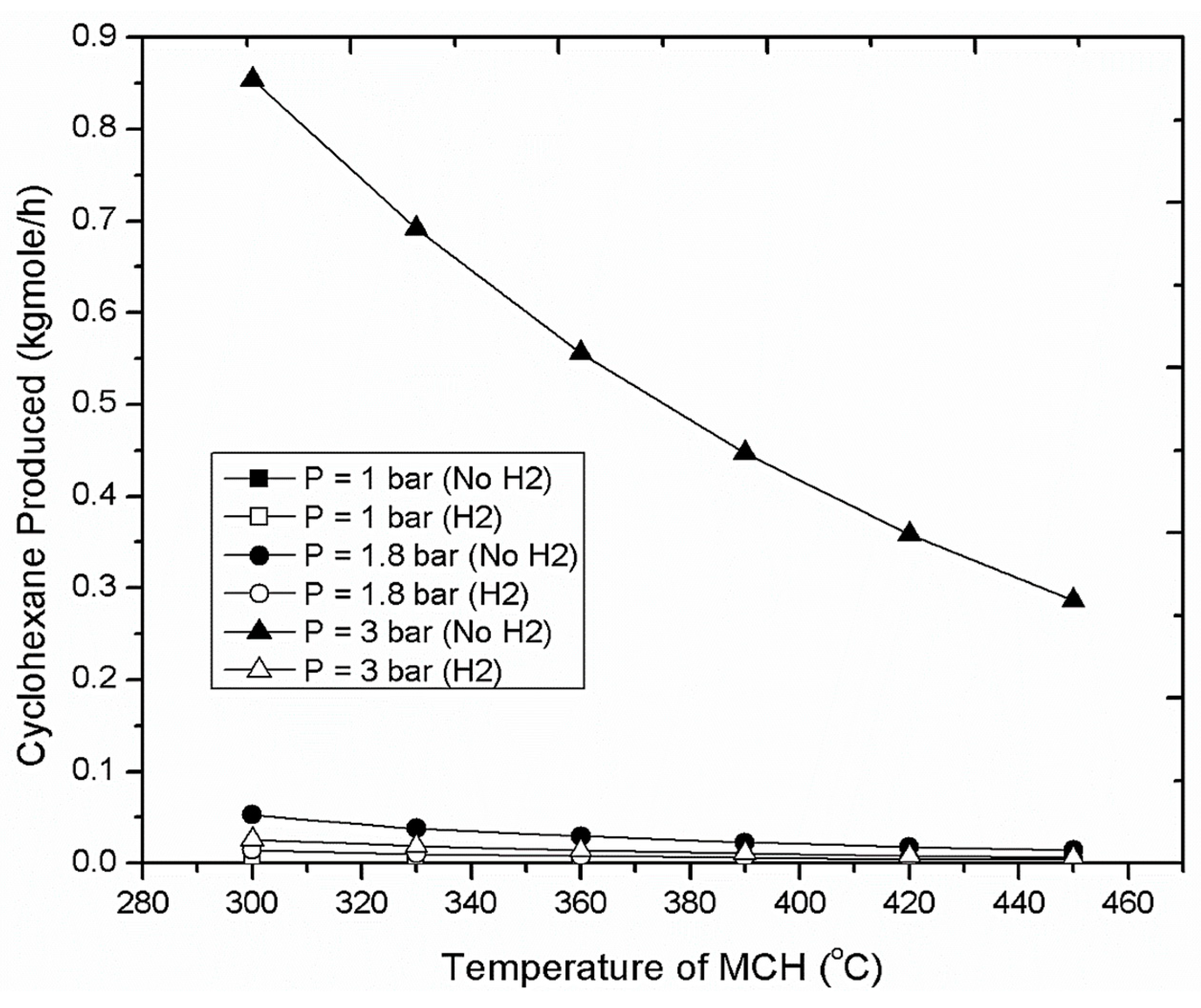
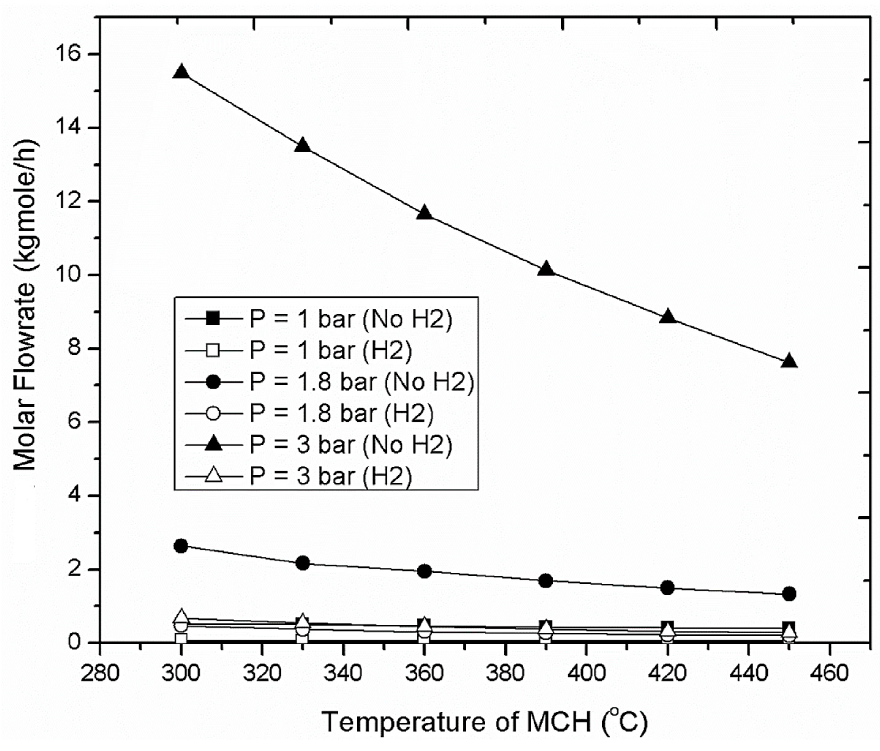
3. Results

The operating parameters are concurrently altered to determine the percentage of methylcyclohexane (MCH) conversion for all the six catalysts used in the parametric study. The parametric study is done considering two cases:
  • H2/MCH ratio = 0
  • H2/MCH ratio = 0.5
The H2/MCH ratio has been defined on weight ratio, and both MCH and H2 are feed into the dehydrogenation reactor in vapor form.
The effect of operational parameters on the methylcyclohexane conversion is presented in Figure 3 for the pressure of 1 bar and temperature range of 300–450 °C. The trend suggests that catalyst-3 and catalyst-5 give the maximum % MCH conversion, i.e., above 99%, followed by catalyst-1, catalyst-4, catalyst-2, while catalyst-1 provides the comparatively lowest percentage of MCH conversion, i.e., a maximum of 95% efficiency at 450 °C.
The effect of operational parameters on the methylcyclohexane conversion is presented in Figure 4 for the pressure of 1.8 bar and temperature range of 300–450 °C. The trend is the same as for the operating pressure of 1 bar. However, in the temperature range of 420–450 °C, the percentage of MCH conversion rate for catalyst-2 is better than catalyst-4, and nearly the same as with catalyst-1, i.e., approximately 93% conversion in this temperature range.
The effect of operational parameters on the methylcyclohexane conversion is presented in Figure 5 for the pressure of 3 bars and temperature range of 300–450 °C. Catalyst-3 gives the highest percentage MCH conversion rate, i.e., a maximum of approximately 92% efficiency at 450 °C. The percentage MCH conversion rates for catalyst-5 and catalyst-4 are comparable at this pressure value and temperature range. However, it remains below 90% even at a temperature of 450 °C. Following these two catalysts, catalyst-1 gives a maximum percentage conversion rate of approximately 78%, catalyst-6 gives a conversion rate of approximately 53%, while catalyst-2 gives the lowest percentage MCH conversion rate, i.e., approximately 44%.
The operating conditions are varied to determine the byproducts formation rate, especially with cyclohexane and benzene. Figure 6 reveals that with the increase in pressure or decrease in temperature of the dehydrogenation reactor feed, the byproducts formation rate increases, while the reverse trend is observed with a decrease in feed pressure of the dehydrogenation reactor, or with an increase in temperature.
The main byproducts considered for the dehydrogenation reactor operation are cyclohexane and benzene. Figure 7 reveals that with the increase in pressure or decrease in temperature of the dehydrogenation reactor feed, the dehydrogenation of cyclohexane to benzene decreases, so at high pressure or low temperature, the cyclohexane is the main byproduct.
With the decrease in pressure or increase in temperature, the cyclohexane dehydrogenation to benzene increases, therefore, the benzene is the main byproduct at low pressure and high temperature, in accordance with the experimental results of Usman et al. [34]. The trend is presented in Figure 8.
The rankings of the catalysts used in the dehydrogenation reactor, with varying conditions of temperature and pressure as demonstrated in Table 7, with 1 being the most effective and 6 being the least effective. The ranking of the catalysts has been decided, which is based on the percentage MCH conversion rate.
The overall ranking of the catalysts is presented in Table 8, with 1 being the most effective and 6 being the least effective. The ranking has been presented under both conditions, i.e., in the absence and presence of hydrogen in the reactor feed. The analysis reveals that the best catalyst understudy is catalyst-3, i.e., 1 wt. % Pt/θ-Al2O3, followed by catalyst-5, i.e., 1 wt. % Pt/γ-Al2O3. As reported by Usman et al., these two catalysts have nearly comparable stability for 250 hours. The stability and activity of catalyst-1, i.e., 0.3 wt. % Pt/Al2O3, start decreasing just after 50 hours [13]. So, this catalyst cannot be used for the process. The use of catalyst-4, i.e., 1 wt. % Pt/β-Zeolite, leads to comparatively increased production of byproducts, thus conversion with this catalyst is not clean. Furthermore, the stability and activity of the catalyst starts decreasing just after 30 hours. Therefore, this catalyst cannot be used for the simulation system [20,21]. The properties of catalyst-6, i.e., 0.3 wt. % Pt-Re/Al2O3, are like that of catalyst-1. Therefore, catalyst-3 and catalyst-5 are superior choices for this system.
The percentage conversion rate of MCH for both catalysts are nearly the same. Thus, for the selection of the catalyst for the simulation study, various parameters were investigated, i.e., surface area, stability, and manufacturing cost. The surface area (BET value) of catalyst-5 is high, i.e., 208 m2/g, while for catalyst-3, the value is 99.1 m2/g. The cost of preparation of catalyst-5 is comparatively low as compared to the catalyst-3, i.e., catalyst-5 is prepared at low temperature, while catalyst-3 is prepared at above 700 °C. Furthermore, both these catalysts have nearly the same stability. Therefore, catalyst-5 has been selected for the study. The following kinetic data has been used for the catalyst-5 in Equations (1)–(4) [22]:
r =   40.907. k . p A . ( 1 p B . p C 3 K . p A ) 1 + 40.907. p A + 22.194. p B + K . p B . p C 2   ( 1 1.471. t d )
K = 3600   .   e x p ( 217650 R   ( 1 T   1 650 ) )
k = 4.064   ×   10 5   . exp ( 7.652   .   ( 1 617.2 T ) )
K = 6.688. e x p ( 24.038 ( 1 617.2 T ) )
A detailed investigation of the system under various operational conditions, followed by ranking, presents that the optimum operating conditions for the operation of the dehydrogenation reaction are:
  • Temperature range = 360–390 °C
  • Pressure range = 1.8–2 bar
  • Addition/concentration of hydrogen, i.e., H2/MCH = 0.5 (by weight)
Percentage of MCH conversion increases with the increase in the feed temperature. However, the increase in temperature leads to decreased operational time of the catalyst, decreasing its activity and stability span. Therefore, the operating range of 360–390 °C is selected. The increase of pressure decreases the rate of conversion in a significant way. Therefore, an optimized pressure range of 1.8–2 bars is selected. Since, the reaction is operating at a high temperature, the catalyst degradation increases than operating at a lower temperature. However, operation at low temperature leads to decreased conversion of the MCH. To overcome this situation, hydrogen addition is carried out with the feed to allow operation of the system at high temperature, improving the stability and activity of the system, by avoiding coke formation on the surface of the catalyst.

4. Conclusions

The parametric study was carried out on Aspen HYSYS v. 9.0 to investigate the dehydrogenation rate of methylcyclohexane for determining the optimum operating conditions and catalyst. The decrease in pressure and increase in temperature resulted in high percentage conversion of methylcyclohexane dehydrogenation and reduced quantities of byproducts. The optimum operating conditions selected for the process were 360 °C and 1.8 bars. The H2/MCH ratio in the feed was maintained as 0.5 for the dehydrogenation system. Although the addition of the hydrogen resulted in a slightly lower methylcyclohexane dehydrogenation rate, it promoted the catalyst activation. The best catalyst found was 1 wt. % Pt/γ-Al2O3, as its manufacturing cost was comparatively lower, and it has a comparatively higher surface area (BET value). The cyclohexane was the main byproduct at high pressure and low temperature, while benzene was found as the main byproduct at the low pressure and high temperature in the dehydrogenation reactor.

Author Contributions

All authors contributed equally to this work. All authors wrote, reviewed, and commented on the manuscript. All authors have read and agreed to the published version of the manuscript.

Funding

This research did not receive any specific grants from funding agencies in the public, commercial, or not-for-profit sectors.

Acknowledgments

The authors are thankful to COMSATS University Islamabad, Lahore Campus for providing access to the registered version of Aspen HYSYS v. 9.0.

Conflicts of Interest

The authors declare no conflicts of interest.

Nomenclature

TTemperature (°C)
PPressure (bar)
LOHCLiquid organic hydrogen carriers
MTHMethylcyclohexane–toluene–hydrogen
MCHMethylcyclohexane
DBTDibenzyl toluene
PDBTPerhydro–dibenzyl toluene
BETBrunauer–Emmett–Teller
−rRate of dehydrogenation reaction (mol kg−1 s−1)
kRate constant for the MCH dehydrogenation reaction
KEquilibrium constant of MCH dehydrogenation reaction, bar3
K’Lumped equilibrium constant, bar−3
tdOnline reaction deactivation time, s
kWh x/kWh hydCalculation of the energy losses (Ex) occurring during a process step (kWhx) relative to the amount of transported energy (kWh hyd) (expressed by the lower heating value of the hydrogen, LHV, 33 kWh/kg)
PLPower Law
LHHWLangmuir–Hinshelwood–Hougen–Watson

References

  1. Müller, K.; Arlt, W. Status and Development in Hydrogen Transport and Storage for Energy Applications. Energy Technol. 2013, 1, 501–511. [Google Scholar] [CrossRef]
  2. Mazloomi, K.; Gomes, C. Hydrogen as an energy carrier: Prospects and challenges. Renew. Sustain. Energy Rev. 2012, 16, 3024–3033. [Google Scholar] [CrossRef]
  3. Teichmann, D.; Arlt, W.; Wasserscheid, P. Liquid Organic Hydrogen Carriers as an efficient vector for the transport and storage of renewable energy. Int. J. Hydrog. Energy 2012, 37, 18118–18132. [Google Scholar] [CrossRef]
  4. Nicoletti, G.; Arcuri, N.; Nicoletti, G.; Bruno, R. A technical and environmental comparison between hydrogen and some fossil fuels. Energy Convers. Manag. 2015, 89, 205–213. [Google Scholar] [CrossRef]
  5. Preuster, P.; Papp, C.; Wasserscheid, P. Liquid Organic Hydrogen Carriers (LOHCs): Toward a Hydrogen-free Hydrogen Economy. Acc. Chem. Res. 2017, 50, 74–85. [Google Scholar] [CrossRef] [PubMed]
  6. Müller, K.; Thiele, S.; Wasserscheid, P. Evaluations of Concepts for the Integration of Fuel Cells in Liquid Organic Hydrogen Carrier Systems. Energy Fuels 2019, 33, 10324–10330. [Google Scholar] [CrossRef]
  7. Wijayanta, A.T.; Oda, T.; Purnomo, C.W.; Kashiwagi, T.; Aziz, M. Liquid hydrogen, methylcyclohexane, and ammonia as potential hydrogen storage: Comparison review. Int. J. Hydrog. Energy 2019, 44, 15026–15044. [Google Scholar] [CrossRef]
  8. Preuster, P.; Fang, Q.; Peters, R.; Deja, R.; Nguyen, V.N.; Blum, L.; Stolten, D.; Wasserscheid, P. Solid oxide fuel cell operating on liquid organic hydrogen carrier-based hydrogen—making full use of heat integration potentials. Int. J. Hydrog. Energy 2018, 43, 1758–1768. [Google Scholar] [CrossRef]
  9. Michalska, K.; Kowalik, P.; Konkol, M.; Próchniak, W.; Stołecki, K.; Słowik, G.; Borowiecki, T. The effect of copper on benzene hydrogenation to cyclohexane over Ni/Al2O3 catalyst. Appl. Catal. A Gen. 2016, 523, 54–60. [Google Scholar] [CrossRef]
  10. Zhu, Q.L.; Xu, Q. Liquid organic and inorganic chemical hydrides for high-capacity hydrogen storage. Energy Environ. Sci. 2015, 8, 478–512. [Google Scholar] [CrossRef]
  11. Modisha, P.M.; Ouma, C.N.M.; Garidzirai, R.; Wasserscheid, P.; Bessarabov, D. The Prospect of Hydrogen Storage Using Liquid Organic Hydrogen Carriers. Energy Fuels 2019, 33, 2778–2796. [Google Scholar] [CrossRef]
  12. Hu, P.; Fogler, E.; Diskin-Posner, Y.; Iron, M.A.; Milstein, D. A novel liquid organic hydrogen carrier system based on catalytic peptide formation and hydrogenation. Nat. Commun. 2015, 6, 6859. [Google Scholar] [CrossRef] [PubMed]
  13. Usman, M.R.; Cresswell, D.L. Options for on-board use of hydrogen based on the methylcyclohexane-totoluene-hydrogen system. Int. J. Green Energy 2013, 10, 177–189. [Google Scholar] [CrossRef]
  14. Sotoodeh, F.; Smith, K.J. An overview of the kinetics and catalysis of hydrogen storage on organic liquids. Can. J. Chem. Eng. 2013, 91, 1477–1490. [Google Scholar] [CrossRef]
  15. Taube, M.; Rippin, D.W.T.; Cresswell, D.L.; Knecht, W. A system of hydrogen-powered vehicles with liquid organic hydrides. Int. J. Hydrog. Energy 1983, 8, 213–225. [Google Scholar] [CrossRef]
  16. Jothimurugesan, K.; Bhatia, S.; Srivastava, R.D. Kinetics of dehydrogenation of methylcyclohexane over a platinum-rhenium-alumina catalyst in the presence of added hydrogen. Ind. Eng. Chem. Fundam. 1985, 24, 433–438. [Google Scholar] [CrossRef]
  17. Mizsey, P.; Cuellar, A.; Newson, E.; Hottinger, P.; Truong, T.B.; von Roth, F. Fixed bed reactor modelling and experimental data for catalytic dehydrogenation in seasonal energy storage applications. Comput. Chem. Eng. 1999, 23, S379–S382. [Google Scholar] [CrossRef]
  18. Usman, M.R. Methylcyclohexane dehydrogenation over commercial 0.3 Wt% Pt/Al2O3 catalyst. Proc. Pak. Acad. Sci. 2011, 48, 13–17. [Google Scholar]
  19. Usman, M.R.; Aslam, R.; Alotaibi, F. Hydrogen Storage in a Recyclable Organic Hydride: Kinetic Modeling of Methylcyclohexane Dehydrogenation Over 1.0 wt% Pt/θ-Al2O3. Energy Sources Part A Recovery Util. Environ. Eff. 2011, 33, 2264–2271. [Google Scholar] [CrossRef]
  20. Usman, M.R. The Catalytic Dehydrogenation of Methylcyclohexane over Monometallic Catalysts for On-board Hydrogen Storage, Production, and Utilization. Energy Sources Part A Recovery Util. Environ. Eff. 2011, 33, 2231–2238. [Google Scholar] [CrossRef]
  21. Usman, M.R.; Alotaibi, F.M.; Aslam, R. Dehydrogenation-hydrogenation of methylcyclohexane-toluene system on 1.0 wt% Pt/zeolite beta catalyst. Prog. React. Kinet. Mech. 2015, 40, 353–366. [Google Scholar] [CrossRef] [Green Version]
  22. Usman, M.R.; Cresswell, D.L. Prototype reactor simulation for on-board use of hydrogen in a hybrid MTH (methylcyclohexane–toluene–hydrogen)–gasoline system and a simplified dynamic modeling for the startup. Chem. Eng. Res. Des. 2015, 104, 125–138. [Google Scholar] [CrossRef]
  23. Chen, Y.-R.; Tsuru, T.; Kang, D.-Y. Simulation and design of catalytic membrane reactor for hydrogen production via methylcyclohexane dehydrogenation. Int. J. Hydrog. Energy 2017, 42, 26296–26307. [Google Scholar] [CrossRef]
  24. Wang, W.; Miao, L.; Wu, K.; Chen, G.; Huang, Y.; Yang, Y. Hydrogen evolution in the dehydrogenation of methylcyclohexane over Pt/CeMgAlO catalysts derived from their layered double hydroxides. Int. J. Hydrog. Energy 2019, 44, 2918–2925. [Google Scholar] [CrossRef]
  25. Obara, S. Energy and exergy flows of a hydrogen supply chain with truck transportation of ammonia or methyl cyclohexane. Energy 2019, 174, 848–860. [Google Scholar] [CrossRef]
  26. Juangsa, F.B.; Prananto, L.A.; Mufrodi, Z.; Budiman, A.; Oda, T.; Aziz, M. Highly energy-efficient combination of dehydrogenation of methylcyclohexane and hydrogen-based power generation. Appl. Energy 2018, 226, 31–38. [Google Scholar] [CrossRef]
  27. Prananto, L.A.; Biddinika, M.K.; Aziz, M. Combined dehydrogenation and hydrogen-based power generation. Energy Procedia 2017, 142, 1603–1608. [Google Scholar] [CrossRef]
  28. Vajda, S.; Pellin, M.J.; Greeley, J.P.; Marshall, C.L.; Curtiss, L.A.; Ballentine, G.A.; Elam, J.W.; Mucherie, S.C.; Redfern, P.C.; Mehmood, F.; et al. Subnanometre platinum clusters as highly active and selective catalysts for the oxidative dehydrogenation of propane. Nat. Mater. 2009, 8, 213–216. [Google Scholar] [CrossRef]
  29. Kuo CTe Lu, Y.; Kovarik, L.; Engelhard, M.; Karim, A.M. Structure Sensitivity of Acetylene Semi-Hydrogenation on Pt Single Atoms and Subnanometer Clusters. ACS Catal. 2019, 9, 11030–11041. [Google Scholar]
  30. Aquilanti, V.; Coutinho, N.D.; Carvalho-Silva, V.H. Kinetics of low-temperature transitions and a reaction rate theory from non-equilibrium distributions. Philos. Trans. R. Soc. A Math. Phys. Eng. Sci. 2017, 375. [Google Scholar] [CrossRef]
  31. Chen, B.; Hoffmann, R.; Cammi, R. The Effect of Pressure on Organic Reactions in Fluids—A New Theoretical Perspective. Angew. Chem. Int. Ed. 2017, 56, 11126–11142. [Google Scholar] [CrossRef] [PubMed] [Green Version]
  32. Pant, A.F.; Özkasikci, D.; Fürtauer, S.; Reinelt, M. The Effect of Deprotonation on the Reaction Kinetics of an Oxygen Scavenger Based on Gallic Acid. Front. Chem. 2019, 7, 680. [Google Scholar] [CrossRef] [PubMed]
  33. Hamayun, M.H.; Hussain, M.; Maafa, I.M.; Aslam, R. Integration of hydrogenation and dehydrogenation system for hydrogen storage and electricity generation-simulation study. Int. J. Hydrog. Energy 2019, 44, 20213–20222. [Google Scholar] [CrossRef]
  34. Usman, M.R.; Cresswell, D.L.; Garforth, A.A. By-Products Formation in the Dehydrogenation of Methylcyclohexane. Pet. Sci. Technol. 2011, 29, 2247–2257. [Google Scholar] [CrossRef]
Figure 1. Overall schematic of the hydrogen-storage system (Adapted from [33]).
Energies 13 00206 g001
Figure 2. Process flow diagram of the methylcyclohexane dehydrogenation.
Energies 13 00206 g002
Figure 3. Effect of catalyst category on percentage of MCH conversion at P = 1 bar, H2/MCH = 0.5.
Energies 13 00206 g003
Figure 4. Effect of catalyst category on the percentage of MCH conversion at P = 1.8 bar, H2/MCH = 0.5.
Energies 13 00206 g004
Figure 5. Effect of catalyst category on percentage of MCH conversion at P = 3 bar, H2/MCH = 0.5.
Energies 13 00206 g005
Figure 6. Effect of change in feed operating conditions on the byproducts’ formation.
Energies 13 00206 g006
Figure 7. Effect of change in feed operating conditions on the cyclohexane flow rate.
Energies 13 00206 g007
Figure 8. Effect of change in feed operating conditions on the benzene flow rate.
Energies 13 00206 g008
Table 1. Global environmental index for various fuels (Adapted from [4]).
FuelEnvironmental Impact (ienv)
Hydrogen0.95 (no water)
0.45
Coal0.82 (no water)
0.78
Gasoline0.76 (no water)
0.72
Methane0.90 (no water)
0.80
Water is not included as it is not considered as a pollutant in the post-combustion process.
Table 2. Energy and cost demands of hydrogen-storage systems (Adapted from [3]).
DescriptionUnitLiquid Organic Hydrogen CarriersCompressed Hydrogen StorageLiquid Hydrogen Storage
Energy DemandkWh x/kWh hyd1.1%3.5%21%
Cost Estimation€/kg hydrogen a0.2380.2430.732
a Depreciation cost + Electricity cost + Operating expenses + Catalyst cost + substitution of LOHC material.
Table 3. Comparison of various hydrogen-storage techniques [7].
CharacteristicLOHCLiquid H2Ammonia (NH3)
Purpose
  • Dehydrogenation followed by hydrogen combustion.
  • Dehydrogenation and purification followed by utilization in the fuel cell.
  • Combustion of H2.
  • Utilization in the fuel cell.
  • Direct combustion
  • Hydrogenation and purification followed by utilization in the fuel cell.
  • Direct fuel cell.
Infrastructure
  • Opportunity to make use of the currently available gasoline infrastructure.
  • Needs further development and construction for a large-scale system.
  • Opportunity to make use of the currently available propane infrastructure.
Auto-Ignition Temperature
  • 283 °C
  • 535 °C
  • 651 °C
Advantages
  • Storage in liquid condition is possible (minimum loss during transportation).
  • Established infrastructure can be used for storage.
  • Storage can be done under existing regulations
  • High purity.
  • Requires no dehydrogenation and purification.
  • Cheapest energy carrier.
  • Direct use is possible.
  • Established infrastructure can be used for storage.
  • Storage can be done under existing regulations
Challenges
  • High temperature source required for the dehydrogenation process.
  • 30% of energy, brought by H2, is used in the dehydrogenation process.
  • Durability (Number of cycles)
  • Requires a very low range of temperatures, i.e., approximately −250 °C.
  • The liquefaction process requires high energy/heat.
  • Demands cost reduction for liquefaction.
  • 45% of energy brought by H2 is consumed by the liquefaction process.
  • Boil-off loss needs to be controlled.
  • Difficulties in long-term storage.
  • Compared to hydrocarbons, NH3 has lower reactivity.
  • Treatment required by certified Engineers, because of pungent smell and toxicity.
  • 13% of energy brought by H2 is consumed in the dehydrogenation and purification processes.
Development Stage
  • Demonstration stage
  • Small scale: application stage
  • Large scale: Setup under development.
  • Research and development stage
  • Partly has entered demonstration stage.
Prospects
  • Energy efficient dehydrogenation.
  • Catalysts for dehydrogenation and hydrogenation processes.
  • Liquefaction process required improvement in energy efficiency.
  • Regulations for transportation, loading/unloading systems.
  • Fuel cell with direct NH3.
  • High energy efficiency in the synthesis stage.
Table 4. Comparison of various liquid organic hydrogen carriers (LOHCs) for hydrogen storage [7,8,9].
CharacteristicsBenzene–Cyclohexane SystemNaphthalene–Decalin SystemDBT–PDBT SystemMCH–Toluene System
Phase under ambient conditionsLiquidSolid + LiquidLiquidLiquid
Temperature (°C)150–250150–250180200–300
Pressure (bar)10–5020–5010–5010–50
Volumetric H2 density (kg-H2.m−3)55.965.45747.4
Gravimetric H2 density (wt. %)7.207.296.26.16
Heat of reaction (kJ.mol−1)205.9319.5588.5204.8
ChallengesHigh melting point and toxicityDehydrogenation process requires high energy consumption, solid in nature, difficult handling.Dehydrogenation process requires high energy consumption.Volatile and inflammable.
Table 5. Catalyst comparison by Usman et al. (Adapted from [20]).
CatalystMCH Conversion (XA) (%)Byproduct Selectivity (%)
1 wt.% Pt/γ-Al2O3920.63
1 wt.% Pt/θ-Al2O3910.10
1 wt.% Pt/β-zeolite7322.48
20 wt.% Ni/γ-Al2O3317.87
Table 6. Catalysts used for the study.
Sr. No.Catalyst TypeModelKinetic ParametersReference
Catalyst-10.3 wt. % commercial Pt/Al2O3Power Lawk = 1.65 × 10⁻⁵
Ea = 100.6
[18]
Catalyst-2Commercial sulfided/spherical alumina supportPower Lawk = 2.335 × 10⁻⁶
Ea = 200
[17]
Catalyst-31 wt. % Pt/θ-Al2O3LHHWk = 6.60 × 10⁻⁵
Ea = 50.2
[19]
Catalyst-41 wt. % Pt/β-ZeolitePower Law
LHHW
k = 1.143 × 10⁻⁵
Ea = 6.0
K’ = 0.3088
[21]
Catalyst-51 wt. % Pt/γ-Al2O3LHHWk = 4.064 × 10⁻⁵
Ea = 54.55
K’ = 0.32
[22]
Catalyst-60.3 wt. % Pt-Re/Al2O3Power Lawk = 1.336 × 10⁻⁵
Ea = 51.9
[16]
Units of k = mols−1 g-cat−1. Pa, Ea = kJ/mol, K = Pa−3.
Table 7. Rankings of the catalyst for operating conditions.
Catalyst TypeP = 1 barP = 1.8 barP = 3 bar
% MCH Conversion (No Hydrogen in Feed)
Catalyst-1333
Catalyst-2556
Catalyst-3111
Catalyst-4444
Catalyst-5222
Catalyst-6665
% MCH Conversion (With Hydrogen in Feed)
Catalyst-1334
Catalyst-2556
Catalyst-3111
Catalyst-4443
Catalyst-5222
Catalyst-6665
Notation 1 means comparatively best performance for studied parameters, and notation 6 means comparatively worst performance.
Table 8. Final rankings of the dehydrogenation reactor catalysts.
Catalyst NumberCatalyst TypeRankings (No H2 in the Feed)Ranking (with H2 in the Feed)
Catalyst-10.3 wt. % Pt/γ-Al2O333
Catalyst-2Sulfided Pt/Al2O355
Catalyst-31 wt. % Pt/θ-Al2O311
Catalyst-41 wt. % Pt/β-Zeolite44
Catalyst-51 wt. % Pt/γ-Al2O322
Catalyst-60.3 wt. % Pt + Re/Al2O366
Notation 1 means comparatively best performance for studied parameters, and notation 6 means comparatively worst performance.

